82
0086 VS 3 Iridium – Visionsense Stereoscopic High Definition (3DHD) including IR Fluorescence Vision System User’s Guide March 2015 Revision 8.2 (EU)
0086
VS3 Iridium – Visionsense Stereoscopic
High Definition (3DHD) including
IR Fluorescence Vision System
User’s Guide
March 2015 Revision 8.2 (EU)

Table of Contents INTRODUCTION ........................................................................................................................... 3
INDICATIONS FOR USE ......................................................................................................................... 4 INTENDED AUDIENCE .......................................................................................................................... 4 ORGANIZATION OF THIS MANUAL .......................................................................................................... 4 CONVENTIONS USED IN THIS MANUAL ................................................................................................... 5
OVERVIEW ................................................................................................................................... 9 VS3 - VISIONSENSE STEREOSCOPIC HIGH DEFINITION (3DHD) VISION SYSTEM ............................................ 10 SYSTEM ARCHITECTURE ..................................................................................................................... 11
PREPARING THE VS3 FOR USE .................................................................................................... 16 DEVICE REPROCESSING ...................................................................................................................... 18 CLEANING AND STERILIZING THE VS3 ENDOSCOPE, CANNULA AND LIGHT GUIDE ........................................... 18 CLEANING THE VS3 ENDOSCOPE, CANNULA AND LIGHT GUIDE .................................................................. 21 CLEANING AND STERILIZING VS3 CAMERA AND COUPLER FOR 2D ENDOSCOPES ........................................... 25 MANUAL CLEANING OF VS3 CAMERA:.................................................................................................. 27 DRAPING OF VS3 CAMERA AND 2D COUPLER IN THE OR ......................................................................... 31 DRAPING THE VS3 IRIDIUM MMS-IR AND Y-LIGHT CABLE ........................................................................ 31 DRAPING THE VS3 IRIDIUM Y-LIGHT CABLE ............................................................................................ 32 POSITIONING THE SYSTEM IN THE CLINIC/OR ENVIRONMENT ................................................................... 33
USING THE VS3 SYSTEM ............................................................................................................. 35 STARTING AND RUNNING THE VISIONSENSE STEREOSCOPIC ENDOSCOPE SYSTEM .......................................... 37 TO USE VS3 IRIDIUM WITH IR FLUORESCENCE DYE ................................................................................. 43 USING VS3’S SPECIAL FEATURES.......................................................................................................... 46 MENU OPTIONS WHEN NO CAMERA IS CONNECTED TO THE SYSTEM ............................................................ 48 MANAGING RECORDINGS .................................................................................................................. 49 MENU OPTIONS WITH CAMERA CONNECTED TO A VS3 STEREOSCOPIC ENDOSCOPE ....................................... 54
MAINTENANCE OF THE VS3 SYSTEM........................................................................................... 59 CHANGING THE ENDOSCOPE AND/OR CAMERA ...................................................................................... 60
VS3 MODULES AND PARTS ......................................................................................................... 62 SYSTEM CONSOLE ............................................................................................................................ 63 DISPLAY UNIT (PRIMARY MONITOR) .................................................................................................... 63 POLARIZING EYE GLASSES .................................................................................................................. 63 SECONDARY MONITOR (OPTIONAL) ..................................................................................................... 63 VSII ENDOSCOPE (OPTIONAL) ............................................................................................................. 63 VS3 ENDOSCOPE & CAMERA .............................................................................................................. 64 ACCESSORIES ................................................................................................................................... 64 SYSTEM POWER CONSUMPTION .......................................................................................................... 64 EQUIPMENT LABELS, SYMBOLS, WARNING STATEMENTS AND ABBREVIATIONS ............................................. 64 LIST OF VS3 ENDOSCOPES AND ACCESSORIES ......................................................................................... 68 LIST OF VSII CAMERAS AND CANNULAS ................................................................................................. 69
TROUBLESHOOTING .................................................................................................................. 71 CLEANING AND STERILIZING THE VSII ENDOSCOPE................................................................................... 76

VS3 User's Manual Rev. 8.2 (EU)
3
Introduction
x Caution: Federal Law restricts this device to sale by or on the order of a licensed physician or healthcare provider.
Chapter One
VS3 User's Manual Rev. 8.2 (EU)
4
Visionsense Ltd. develops, manufactures and markets advanced stereoscopic visualization systems for the minimally invasive surgery (MIS).
Visionsense Ltd. develops, manufactures and markets advanced stereoscopic visualization systems for the minimally invasive surgery (MIS). Visionsense’s revolutionary vision system, the VS3, is the world's most advanced stereoscopic endoscope to offer depth perception with high-resolution through small endoscope diameters.
Indications for Use The VS3 Iridium is intended for viewing anatomical structures during invasive surgery and for viewing fluorescent images for the visual assessment of blood flow, as an adjunctive method for the evaluation of tissue perfusion, and related tissue-transfer circulation in tissue and free flaps used in general, plastic, micro- and reconstructive surgical procedures.
Intended Audience This manual is intended for physicians/surgeons and support staff using the VS3. The manual covers procedures for preparing the system for use, using the system during procedures/surgery, as well as troubleshooting.
Organization of this Manual This guide assumes that the authorized personnel have already prepared the VS3 system for use.
Chapter 2, “Overview”, describes the VS3 system.
Chapter 3, “Preparing the VS3 System for Use”, describes the steps you must take after installation to prepare the VS3 for use in the clinic or operating room.
Chapter 4, “Using the VS3 System”, describes procedures performed during and after procedural/surgical use of the system.
Chapter 5 “Appendix: Parts and Modules”, provides details on the VS3 system’s hardware.
Chapter 6, “Troubleshooting the VS3 System”, describes some minor problems that can be resolved by authorized clinic/hospital personnel.

VS3 User's Manual Rev. 8.2 (EU)
5
Conventions Used in this Manual The following typographic conventions are used in this manual:
Symbol Text Meaning
Warning Indicates that the personal safety of the patient or physician may be involved. Disregarding a warning could result in injury to the patient or physician.
Caution Indicates that the particular procedures or precautions must be followed to avoid possible damage to the product.
Note Indicates information that may be helpful in the operation of the product.
The terms endoscope, laparoscope and camera are used interchangeably throughout the manual, all referring to the VSII and VS3 endoscopes.
Safety Instructions Read this manual and carefully follow its instructions. The words Warning and Caution indicate special information that must be carefully reviewed to ensure the safe and effective operation of this product. Note that these words are accompanied by graphic symbols as indicated in the above section, Conventions Used in this Manual.
Warnings
Adhere to the following safety rules:
x Familiarize yourself with how the unit operates and is controlled, before using the unit on the patient.
x Only qualified personnel should operate the unit.
!
!
i
i
!

VS3 User's Manual Rev. 8.2 (EU)
6
Warnings
x The unit is indicated for viewing internal surgical sites during general surgical procedures, for use in visualization of ventricles and structures within the brain during neurological surgical procedures, as well as viewing internal surgical sites during anterior and posterior spinal procedures, such as nucleotomy, discectomy, and foraminotomy, and to visualize the nasal cavity, nasal pharynx, upper airway, vocal cords, external ear canal and tympanic membrane during diagnostic and therapeutic procedures. Use of the unit in fields other than those indicated is not allowed for safety reasons.
x Unauthorized modifications to the unit are not allowed for safety reasons.
x Before using the unit, it is the user’s responsibility to make sure that the unit is safe and operates properly.
x The device cannot be used through instrumentation or an opening smaller than the outer diameter of the endoscope.
x When using the endoscope (through the same orifice) with other endoscopic equipment and/or endoscopically-used accessories, such as high frequency surgical equipment, laser equipment, or other medical electrical equipment, the combination should be comply with IEC 601-2-18 standard.
x During treatment with the unit, the patient must be treated with the usual medical care. This includes regular observation, checking on the progress of treatment, monitoring treatment conditions, etc.
x Avoid looking directly into a working endoscope (camera) tip for avoiding temporarily dazzle. If this happens, simply shift endoscope tip aside or alternatively unplug endoscope immediately.
x The Visionsense VS3 stereoscopic endoscopy module should ONLY be used by personnel with endoscopy experience in the surgical operating theater.
x The Visionsense VS3 stereoscopic endoscopy module should ONLY be used by personnel who have been formally trained on the operation of the system. Do not use the system without proper training.
x Do not use the endoscope to touch, push, perforate, or mechanically stress the tissue in any way. This is improper use as the device is not designed for this type of functionality. The endoscope should only be used for visualization and the tip should be kept away from tissue to enable a viewable image.
!

VS3 User's Manual Rev. 8.2 (EU)
7
x Do not mechanically modify the device in any way (e.g.: do not try to polish the endoscope shaft or window). This will likely render the device unusable and may lead to an unsafe condition.
x If the device has been improperly used (e.g.: setting changes have been incorrectly made) , the most likely outcome will be either a very poor image (blurry and noisy) or no image at all. If you see these effects, discontinue using the device and use an alternate endoscopy system to complete the surgical procedure until a trained technical person returns the device to a proper state.
Warnings
x This medical device complies with EN60601-1-2 safety standard for electromagnetic compatibility, requirements and test. However, if this equipment is operated in the presence of high levels of electromagnetic interference (EMI) or highly sensitive equipment, interference may be encountered and the user should take whatever steps are necessary to eliminate or reduce the source of the interference. Diminished performance may lengthen operating time for anesthetized patient.
x If the glass window on the tip of the endoscope becomes coated with blood or bodily tissue, visualization will be disrupted. If this occurs, withdraw and wipe the endoscope tip; or, if the clinical situation permits, irrigate the tip with sterile water to remove the coating.
x Do not position the VS3 Iridium Microscope closer than 20cm from tissue
x Do not look directly into the laser illuminator on the bottom of the VS3 Iridium Scopes (MMS-IR or endoscope).
x Do not point the VS3 Iridium scope (MMS-IR or endoscope) at open eyes of the patent. If the device must be used to observe the patient's face, be sure that the eyes are closed and protected from 805nm laser light.
The device described in this manual has been designed and tested in accordance with Visionsense safety standards as well as European and international standards.
This guarantees a high degree of instrument safety. The system described in this user manual has been designed in compliance with the requirements of: EN, IEC, UL and CSA. In accordance with Directive 93/42/EEC & MDD 2007/47 for medical devices, the complete quality management system according to ISO 13485 of Visionsense, has been certified by notified body BSI (British Standards Institution), number 0086.
i
!
i
VS3 User's Manual Rev. 8.2 (EU)
8
Equipment Compliance The VS3 has been tested and found to comply with the following standards:
Safety regulations:
IEC/EN-60601-1 (2006)
IEC/EN60601-2-18 (2009)
IEC/EN60825-1 (2014)
EMI regulations: IEC/EN60601-1-2 (2007)
Equipment Classification: According to the type of protection against electric shock: Class I equipment.
According to the degree of protection against electrical shock: Type BF Applied Part.
According to the mode of operation: Continuous operation.
Customer Support In the event of any technical difficulties with your Visionsense equipment, contact your Visionsense representative. For your convenience, the contact information is as follows:
Customer Support: Tel: +1-866-632-0907
e-mail: [email protected]
Israeli Office USA Office MDD - Authorized Representative in Europe
Visionsense Ltd. Visionsense Corp. MEDES LIMITED
20 Hamagshimim Street 1270 Avenues of the Americas, Suite #302
5 Beaumont Gate, Shenley Hill
Petach Tikva, 49348 New York, NY 10020 Radlett, Herts, WD7 7AR
ISRAEL USA ENGLAND
Tel: +972-3-924-4339 Tel: 845-680-0233 Tel: +423-663-169205
Fax: +972-3-924-4335 Fax: 845-503-2256 Tel/Fax: +44-192-385-9810

VS3 User's Manual Rev. 8.2 (EU)
9
Overview
Chapter Two
VS3 User's Manual Rev. 8.2 (EU)
10
VS3 - Visionsense Stereoscopic High Definition (3DHD) Vision System Standard monocular endoscopes and video monitors flatten the view of the patient’s anatomy in two dimensions. This lack of depth perception can significantly reduce the physician’s/surgeon’s perception of size and accurate location of the treated tissues, and thus potentially reduce the ability to diagnose and operate.
The VS3 – Visionsense Stereoscopic High Definition (3DHD) Vision System remedies this constraint of traditional endoscopic systems by providing the physician with natural stereoscopy, the two-eyed ability to judge depth, volume, or distance accurately. ‘Stereo vision’ is obtained when the eyes simultaneously pick up two slightly different images of the same object (right and left). VS3’s technology provides physicians/surgeons with such stereo vision, enabling depth perception and so enhancing diagnostic and surgical judgment capabilities in the course of the surgical procedure. The image is picked up using a miniature proprietary sensor (a few mm.in size) and enhanced by an external, software-driven, digital video image processor.
In addition to traditional endoscopic procedures VS3 system includes support for Infrared (IR) Fluorescence visualization (hereafter referred to as Iridium). Iridium utilizes the VS3 system with both an endoscope and a special scope (called Miniature Microscope or MMS-IR) that is positioned 20cm to 40cm above the patient during the surgical procedure.
VS3 Iridium modules including Miniature Microscope (MMS-IR) and Iridium endoscope (endoscope-IR) are designed to work with an approved IR fluorescence dye (principally Indocyanine Green or ICG) which has excitation at 805nm and emission band between 825nm and 850nm. VS3 Iridium provide excitation light to the surgical field to excite the dye molecules and captures emission from the dye using an IR camera. VS3 Iridium allows the capture of normal (white) light image in parallel with the fluorescence IR image and display both to the surgeon to provide a rich view of the anatomy.
The VS3 system permits recording surgical procedures, storing them on removable storage devices, and playing the procedures back.
VS3 User's Manual Rev. 8.2 (EU)
11
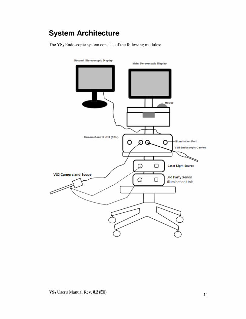
System Architecture The VS3 Endoscopic system consists of the following modules:

VS3 User's Manual Rev. 8.2 (EU)
12
The VS3 Endoscope Module The VS3 Endoscope Module includes: x High Definition 3D Endoscope
x High Definition 3D Camera with 3 control buttons and a focus adjustment knob
x Coupler for 2D Endoscopes (namely: “2D Coupler”) enables working with standard 3rd party 2D endoscopes. (optional)
x VS3 Irrigation Cannula (optional)
To begin procedures, the endoscope must be connected to the camera by attaching the back of the endoscope to the camera’s coupler while pressing the spring. Once the back of the endoscope is in the camera’s coupler, the spring should be released to lock the scope and the camera together. The fiber optic Light Guide should be connected to the scope via a standard endoscope Light Guide connector with a screw terminal. The focus knob can be used during the surgical procedure to adjust the focus of the module based on distance from the objects in the surgical field.
To uncouple the endoscope from the camera, depress the spring and detach the endoscope from the camera by pulling it straight out of the coupler. The Light Guide should be detached from the endoscope by unscrewing the connector.
Warning
x Do not hold the camera in any way that will apply pressure on the spring during use as this may disengage the endoscope.
Figure 1: VS3 Endoscopic module including Endoscope and Camera
3D HD Endoscope
3D HD Camera
Spring Light Guide Connector
Focus Knob
!
VS3 User's Manual Rev. 8.2 (EU)
13
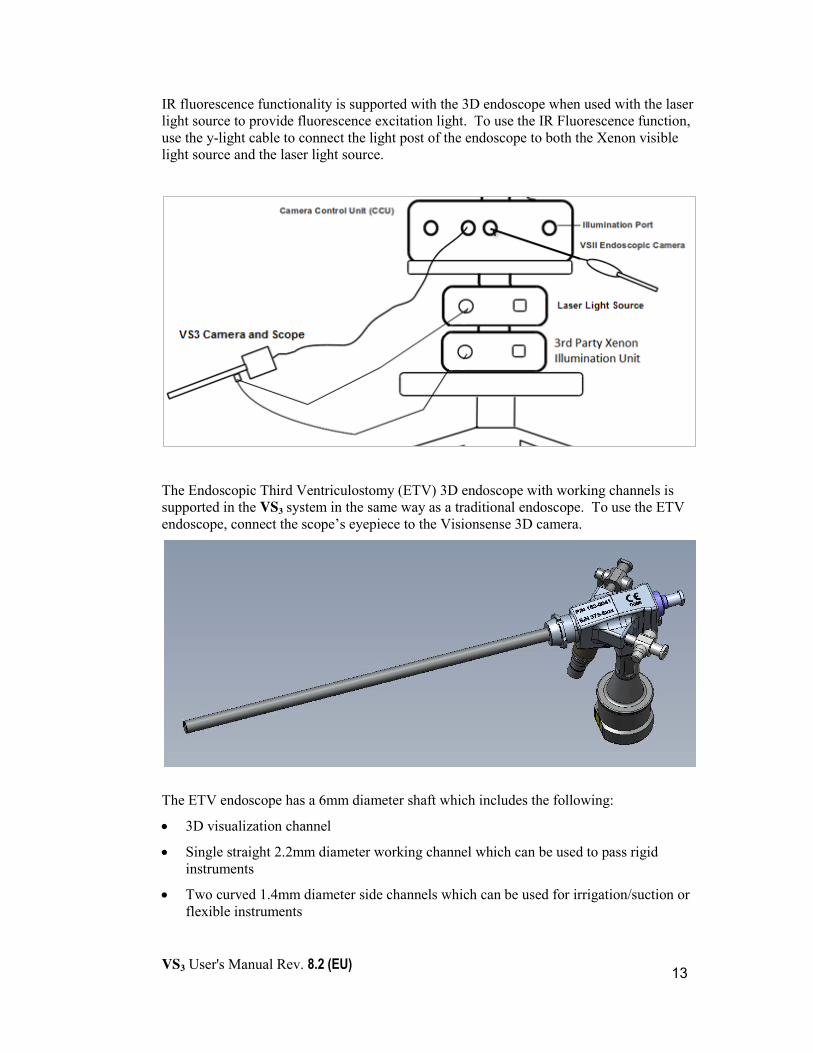
IR fluorescence functionality is supported with the 3D endoscope when used with the laser light source to provide fluorescence excitation light. To use the IR Fluorescence function, use the y-light cable to connect the light post of the endoscope to both the Xenon visible light source and the laser light source.
The Endoscopic Third Ventriculostomy (ETV) 3D endoscope with working channels is supported in the VS3 system in the same way as a traditional endoscope. To use the ETV endoscope, connect the scope’s eyepiece to the Visionsense 3D camera.
The ETV endoscope has a 6mm diameter shaft which includes the following:
x 3D visualization channel
x Single straight 2.2mm diameter working channel which can be used to pass rigid instruments
x Two curved 1.4mm diameter side channels which can be used for irrigation/suction or flexible instruments
VS3 User's Manual Rev. 8.2 (EU)
14
The VS3 coupler for 2D Endoscopes
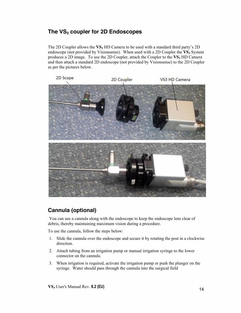
The 2D Coupler allows the VS3 HD Camera to be used with a standard third party’s 2D endoscope (not provided by Visionsense). When used with a 2D Coupler the VS3 System produces a 2D image. To use the 2D Coupler, attach the Coupler to the VS3 HD Camera and then attach a standard 2D endoscope (not provided by Visionsense) to the 2D Coupler as per the pictures below.
Cannula (optional) You can use a cannula along with the endoscope to keep the endoscope lens clear of debris, thereby maintaining maximum vision during a procedure.
To use the cannula, follow the steps below:
1. Slide the cannula over the endoscope and secure it by rotating the post in a clockwise direction.
2. Attach tubing from an irrigation pump or manual irrigation syringe to the lower connector on the cannula.
3. When irrigation is required, activate the irrigation pump or push the plunger on the syringe. Water should pass through the cannula into the surgical field
VS3 User's Manual Rev. 8.2 (EU)
15
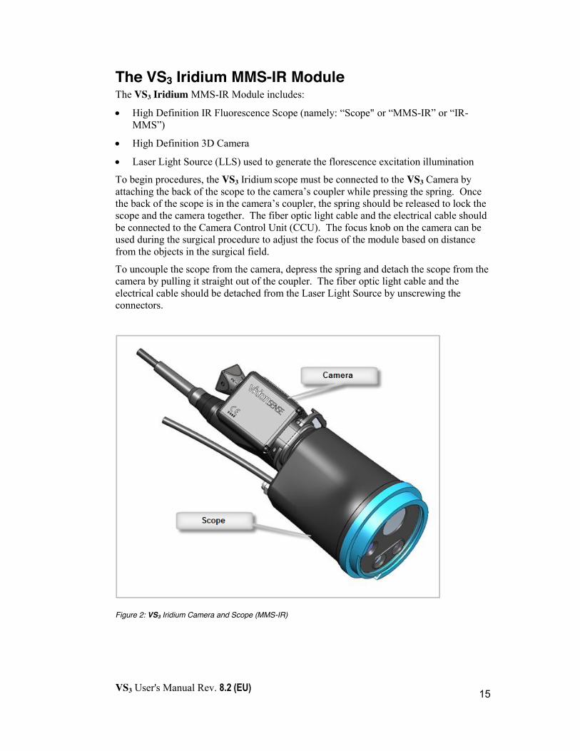
The VS3 Iridium MMS-IR Module The VS3 Iridium MMS-IR Module includes:
x High Definition IR Fluorescence Scope (namely: “Scope" or “MMS-IR” or “IR-MMS”)
x High Definition 3D Camera
x Laser Light Source (LLS) used to generate the florescence excitation illumination
To begin procedures, the VS3 Iridium scope must be connected to the VS3 Camera by attaching the back of the scope to the camera’s coupler while pressing the spring. Once the back of the scope is in the camera’s coupler, the spring should be released to lock the scope and the camera together. The fiber optic light cable and the electrical cable should be connected to the Camera Control Unit (CCU). The focus knob on the camera can be used during the surgical procedure to adjust the focus of the module based on distance from the objects in the surgical field.
To uncouple the scope from the camera, depress the spring and detach the scope from the camera by pulling it straight out of the coupler. The fiber optic light cable and the electrical cable should be detached from the Laser Light Source by unscrewing the connectors.
Figure 2: VS3 Iridium Camera and Scope (MMS-IR)

VS3 User's Manual Rev. 8.2 (EU)
16
Preparing the VS3 for Use
Chapter Three
VS3 User's Manual Rev. 8.2 (EU)
17
This chapter describes how you prepare the equipment for use in the clinical and/or operating room during an endoscopic procedure. It describes what you need to do after the VS3 System has been assembled and connected to the outlet.
The following steps describe what needs to be done to prepare the VS3 for use:
x Clean and disinfect or sterilize the Endoscope using the appropriate process, i.e. STERRAD® or Autoclave (valid for marked Autoclave approved endoscopes).
x Deliver the unit to the clinic/operating room, in accordance with institutional regulations for handling disinfected/sterilized equipment.
x Position the VS3 System in the clinic/OR Environment.
x Make sure that the stereoscopic glasses are present.
x (OPTIONAL) Connect the mouse to one of the USB ports in the back of the console.
(OPTIONAL) Connect the second stereo or monocular monitor to the VS3 console.
The following reprocessing instructions include cleaning and sterilization instructions for VS3 Camera, Cannula, Light Guide and 2D Coupler.
For the reprocessing guide for the optional VSII Endoscope and cannula, see Appendix A.
The VS3 Iridium MMS-IR does not support sterilization. This scope should be draped using an approved sterile drape prior to use in the sterile field.
The VS3 Iridium y-light cable used for the IR functionality with the endoscope does not support sterilization. This scope should be draped using an approved sterile drape prior to use in the sterile field.
This chapter assumes that your Visionsense service representative has already assembled the system.
i
i
i
VS3 User's Manual Rev. 8.2 (EU)
18
Device Reprocessing Reprocessing begins at point of use. Immediately following use of the device, ensure that the reusable device remains segregated from waste. Decontaminate the reusable device by wiping the device clean of all visible soil and keeping the wiped device contained while it is being transported to the dedicated cleaning work area at your facility. This initial wiping is intended to render the device safe for handling by health care workers and to make the device suitable for the subsequent thorough cleaning and sterilization steps. The device at this point is only safe for handling by the health care worker and is not suitable to be used on patients.
Once the device is at the designated cleaning work area, thoroughly clean the device in accordance with the cleaning instructions in the following sections. Use only the compatible cleaning detergents specified on the following pages of this manual to thoroughly clean the device, then rinse and dry the devices as described above to remove any unsafe residues.
The thoroughly cleaned device should then be terminally sterilized in accordance with the directions in this manual following the cleaning directions. Once the device has been thoroughly cleaned AND sterilized, it may be returned to service in accordance with your hospital’s standard procedures.
Cleaning and Sterilizing the VS3 Endoscope, Cannula and Light Guide The VS3 Endoscope, Cannula and Light Guide must be cleaned and sterilized before being used in a surgical procedure. The following sections describe the materials and procedures required for the cleaning and sterilization processes:
x Materials Required for Cleaning and Sterilization
x Cleaning the Endoscope, Cannula and Light Guide
x Sterilizing and Handling the Endoscope, Cannula and Light Guide
Materials Required for Cleaning and Disinfection or Sterilization The authorized clinic/hospital personnel will need the following materials to carry out the processes of cleaning and sterilizing the VS3 endoscopes:
x Cleaning agents: - Enzymatic Detergent1
- Non-Enzymatic Detergent2 1 ENDOZIME®, RUHOF CORP. Enzymatic Detergent was validated for cleaning efficacy

VS3 User's Manual Rev. 8.2 (EU)
19
- Any cleaning solution that is approved by your institution's protocol for endoscopic equipment
x Tap water x Sterile water x Large water basin (approximately 40cm X 40cm X 20cm) x Scrub brush (such as the “3M brush team”) x Sterile gauze pads x Sterile, no powder gloves x Protective attire according to institutional protocol x Endoscope and protective cap x Sterilization box
Preparing the VS3 Endoscope 30° for cleaning and sterilization In order to prepare the VS3 Endoscope 30° for cleaning, the Eyepiece must be detached from the main Endoscope body. These two parts are attached by a magnet, and need to be pulled away in order to separate them.
To detach the eyepiece from the main Endoscope body, do the following:
1. Hold the Endoscope firmly by its main body, near the light post. Do not hold the Endoscope by the shaft!!!
2. With your other hand, hold the eyepiece firmly.
3. Rotate the eyepiece so that the red dot is aligned with the light post.
4. Gently detach the eyepiece from the scope body as shown in the following images:
2 RENU-KLENZ®, STERIS CORP. Non-Enzymatic Detergent was validated for cleaning efficacy

VS3 User's Manual Rev. 8.2 (EU)
20
Figure 3: Gently detach -- do not pull
Figure 4: Complete the detachment
Figure 5: Detached eyepiece and main body of VS3 Endoscope 30°

VS3 User's Manual Rev. 8.2 (EU)
21
Cleaning the VS3 Endoscope, Cannula and Light Guide Both new endoscopes and those previously used in a procedure must be cleaned before disinfection or sterilization. When the physician/surgeon has finished using an endoscope, it must be promptly prepared for cleaning by the authorized personnel.
Manual Cleaning of VS3 Endoscope, Cannula and Light Guide To thoroughly clean the endoscope, cannula and Light Guide:
1. Wipe excess soil from the device with disposable paper towels. 2. Soak in enzymatic detergent:
x Prepare an enzymatic detergent solution with lukewarm tap water according to manufacturer’s recommendations.
x Wipe the entire surface of the device using a soft clean cloth dipped in the detergent solution.
x Immerse the device in the detergent solution, ensuring the solution reaches all outer surfaces of the device.
x Soak the device in the solution for a minimum of 15 minutes.
3. Brush
x Thoroughly brush the exterior of the device with a soft-bristled brush. Do not use an abrasive sponge under any circumstances.
x Thoroughly clean the lumens (working channels) of the ETV scope with an appropriate brush. The ETV scope has 3 working channels. A single 2.2mm diameter straight channel and two 1.4mm diameter curved channels.
x When cleaning the Cannula, use appropriate brushes to clean the lumen of the Cannula as well.
4. Rinse
x Remove the device from the detergent solution and rinse it with water at ambient temperature, for at least one minute, until all visible detergent is removed. Run Cleaning solution through Cannula lumen
x Rinse the device for an additional 30 seconds.
x Drain any excess water from the device by holding it at an incline.
5. Soak in Non-Enzymatic Detergent

VS3 User's Manual Rev. 8.2 (EU)
22
x Prepare a non-enzymatic solution in lukewarm tap water according to manufacturer’s recommendations.
x Immerse the device in the detergent solution, making sure the solution reaches all inner and outer surfaces of the device.
x Soak the device in the solution for a minimum of 15 minutes.
6. Brush x While submerged in solution, thoroughly brush the device. When
cleaning the Cannula, use appropriate brushes to clean the lumen of the Cannula as well.
x Thoroughly clean the lumens (working channels) of the ETV scope with an appropriate brush. The ETV scope has 3 working channels. A single 2.2mm diameter straight channel and two 1.4mm diameter curved channels.
7. Rinse
x Remove the device from the detergent solution and rinse it with water at ambient temperature, for at least on minute, until all visible detergent is removed.
x Flush all lumens, crevices, and mated surfaces with a minimum of 50mL of water.
x After all detergent residues are removed rinse the device for an additional 30 seconds.
x Drain any excess water from the device by holding it at an incline.
8. Dry
x Dry the device using a clean cloth. Filtered pressurized air can be used to assist in drying.
x Leave in open air for ten minutes to ensure it is completely dry.
9. Inspect x Visually inspect the device for remaining soil.
x If soil remains, repeat the manual cleaning procedure, focusing on those areas.
x After the cleaning has been completed, the endoscope can be stored or sterilized for immediate use.
Automated Cleaning of VS3 Endoscope, Cannula, and Light Guide
Perform the following procedure for automated cleaning:
1. Rinse the Endoscope, Cannula, and Light Guide in warm tap water to remove any tissue debris and/or bloody residue.

VS3 User's Manual Rev. 8.2 (EU)
23
2. Place the Endoscope, Cannula, and Light Guide in the sterilization tray. Make sure that the Endoscope is properly fixated in the sterilization tray. Place the distal part of the Endoscope (shaft) through the silicon fixation opening and the proximal thick part of the Endoscope between the silicon fixations. Ensure that the Light Guide is neatly placed in the sterilization tray and free of kinks. Keep the Light Guide ends in the middle of the sterilization tray (see figure below).
3. Each of the modules (Endoscope, Cannula, and Light Guide) may be placed in separate sterilization trays if needs to be cleaned by itself (see figures below).
4. Use the automated washer according to hospital protocol for using such a cleaner.3
5. After the cleaning has been completed, the Endoscope, Cannula, and/or Light Guide can be stored or disinfected/sterilized for immediate use.
Figure 6: Stored Endoscope, Cannula and/or Light Guide
Figure 7: Endoscope and Cannula Sterilization tray
3 Visionsense has validated an automated washer cycle of 5 minutes at 50°-60°C (washing), and additional 5 minutes at 90°-95°C (Disinfection).
VS3 User's Manual Rev. 8.2 (EU)
24
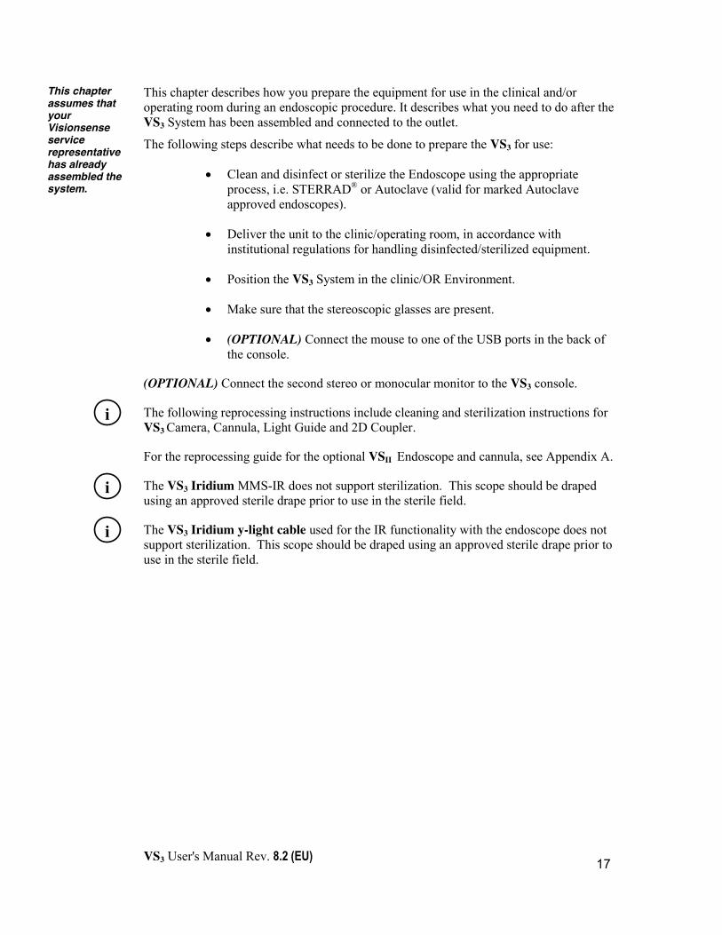
Figure 8: VS3 Light Guide Sterilization tray
After the cleaning has been completed, the Endoscope, Cannula, and/or Light Guide can be stored or disinfected/sterilized for immediate use.
Terminally Sterilizing the VS3 Endoscope, Cannula, and Light Guide The VS3 endoscopic equipment is supplied non-sterile and must be terminally sterilized by authorized clinic/hospital personnel prior to use. In the current version of the VS3 system, authorized personnel can sterilize the VS3 Endoscope, Cannula, and Light Guide using low temperature sterilization processes, such as STERRAD® (STERRAD® 50/100S/200/NX/100NX Systems) or steam autoclave at 134°C for at least 3 minutes.
Cautions Note the following precautions prior to sterilizing the VS3 Endoscope, Cannula and Light Guide:
x Follow manufacturer instructions for sterilization.
x Ultrasonic cleaning methods are prohibited when cleaning or sterilizing the VS3 Endoscope, Cannula and/or Light Guide.
x Do not sterilize the VS3 Endoscope, Cannula and Light Guide using gamma irradiation
x Do not use cleaning and/or sterilization processes that have not been validated.
!
VS3 User's Manual Rev. 8.2 (EU)
25
Warning
x This device is used in the neurosurgical field where there is a high-infectivity risk of Creutzfeldt-Jakob disease (a.k.a. TSE, CJD) or similar prions in patients who are known or suspected to be infected. Dispose or destroy devices that have been used on patients suspected of having Creutzfeldt-Jakob disease or other prion diseases according to the WHO guidelines, unless sterilizing the devices with STERRAD 100NX Standard Cycle process which is currently thought to eradicate prions. This device is fabricated of materials which can withstand the reprocessing exposure conditions of STERRAD 100NX sterilization. To learn more about this disease you may wish to consult the WHO guidelines - World Health Organization’s 1999 guidance document (Infection Control Guideline for Transmissible Spongiform Encephalopathies. Geneva, Switzerland).
x The qualified ASP STERRAD® Sterilization Systems are: STERRAD® 50, 100S, 200, NX Standard Cycle, and 100NX, Standard and DUO Cycles only (100NX Express Cycle is not qualified). Please refer to ASP/ STERRAD® System User’s Guide for the appropriate cycle in each STERRAD® system for the instrument to be reprocessed. All instruments must be cleaned, rinsed, and thoroughly dried prior to placement in a STERRAD® sterilizer.
Cleaning and Sterilizing VS3 Camera and Coupler for 2D Endoscopes The VS3 Camera and 2D Coupler must be cleaned and sterilized before being used in a surgical procedure. The following sections describe the materials and procedures required for the cleaning and sterilization processes:
x Materials Required for Cleaning and Sterilization
x Cleaning the Camera and 2D Coupler
x Sterilizing and Handling the Camera and 2D Coupler
Materials Required for Cleaning and Disinfection or Sterilization The authorized clinic/hospital personnel will need the following materials to carry out the processes of cleaning and sterilizing the VS3 Camera and 2D Coupler:
x Cleaning agents:
!
VS3 User's Manual Rev. 8.2 (EU)
26
- Enzymatic Detergent1
- Non-Enzymatic Detergent4
- Any cleaning solution that is approved by your institution's protocol for endoscopic equipment - See the following cautions:
Cautions
¾ Cleaning agents must state Aluminum Suitability by the manufacturers ¾ Cleaning agents should be up to pH=10.0
x Tap water x Sterile water x Large water basin (approximately 40cm X 40cm X 20cm) x Scrub brush (such as the “3M brush team”) x Sterile gauze pads x Sterile, no powder gloves x Protective attire according to institutional protocol x Endoscope and protective cap x Sterilization box
Cleaning the VS3 Camera and Coupler for 2D Endoscopes Both new cameras and those previously used in a procedure must be cleaned before disinfection or sterilization. When the physician/surgeon has finished using a camera, it must be promptly prepared for cleaning by the authorized personnel.
MANDATORY - Prior to any cleaning or immersing, make sure to cover the male part of the medical connector attached to the camera’s main cable with the protective cap and to properly tighten the cap.
Cautions
x Failure to cover the camera’s connector will result in irreparable damage to the camera.
x Ultrasonic cleaning methods are prohibited when cleaning or sterilizing the camera or 2D Coupler. Cleaning must be done by hand only.
7RENU-KLENZ®, STERIS CORP. Non-Enzymatic Detergent was validated for cleaning efficacy
!
!

VS3 User's Manual Rev. 8.2 (EU)
27
Manual Cleaning of VS3 Camera: To thoroughly clean the VS3 Camera:
1. Prepare x Ensure the protective cap is screwed over the connector at the end of the
cable, to protect from liquids. Roll the cable with a radius of at least 10 inches.
2. Wipe
x Wipe excess soil from the device (“device”: the full camera, including the cable & connector cap) with disposable paper towels.
3. Soak in enzymatic detergent: x Prepare an enzymatic detergent solution with lukewarm tap water according
to manufacturer’s recommendations.
x Wipe the entire surface of the device using a soft clean cloth dipped in the detergent solution.
x Immerse the device in the detergent solution, ensuring the solution reaches all outer surfaces of the device.
x Soak the device in the solution for a minimum of 15 minutes.
4. Brush
x Thoroughly brush the exterior of the device with a soft-bristled brush. Do not use an abrasive sponge under any circumstances.
5. Rinse
x Remove the device from the detergent solution and rinse it with water at ambient temperature, for at least on minute, until all visible detergent is removed.
x After all detergent residues are removed, rinse the device for an additional 30 seconds.
x Drain any excess water from the device by holding it at an incline.
6. Soak in Non-Enzymatic Detergent x Prepare a non-enzymatic solution in lukewarm tap water according to
manufacturer’s recommendations.
x Immerse the device in the detergent solution, making sure the solution reaches all inner and outer surfaces of the device.
x Soak the device in the solution for a minimum of 15 minutes.
7. Brush x While submerged in solution, thoroughly brush the device, including in the
inner area of the spring, with an appropriately sized brush.

VS3 User's Manual Rev. 8.2 (EU)
28
8. Rinse x Remove the device from the detergent solution and rinse it with water at
ambient temperature, for at least one minute, until all visible detergent is removed.
x Flush all lumens, crevices, and mated surfaces with a minimum of 50mL of water.
x After all detergent residues are removed rinse the device for an additional 30 seconds.
x Drain any excess water from the device by holding it at an incline.
9. Dry
x Dry the device using a clean cloth. Filtered pressurized air can be used to assist in drying.
x Leave in open air for ten minutes to ensure it is completely dry.
10. Inspect x Visually inspect the device for remaining soil.
x If soil remains, repeat the manual cleaning procedure, focusing on those areas.
x After the cleaning has been completed, the endoscope can be stored or sterilized for immediate use.
Manual Cleaning of VS3 Coupler for 2D Endoscopes VS3 Coupler for 2D Endoscopes (“2D Couplers”) is reusable and must be thoroughly cleaned after each use to remove contaminating substances prior to sterilization.
To thoroughly clean the 2D Coupler after each use: 1. Wipe
x Wipe excess soil from the device with disposable paper towels.
2. Soak in enzymatic detergent:
x Prepare an enzymatic detergent solution with lukewarm tap water according to manufacturer’s recommendations.
x Wipe the entire surface of the device using a soft clean cloth dipped in the detergent solution.
x Immerse the device in the detergent solution, ensuring the solution reaches all outer surfaces of the device.
x Soak the device in the solution for a minimum of 15 minutes.
3. Brush

VS3 User's Manual Rev. 8.2 (EU)
29
x Thoroughly brush the exterior of the device with a soft-bristled brush. Do not use an abrasive sponge under any circumstances.
4. Rinse
x Remove the device from the detergent solution and rinse it with water at ambient temperature, for at least on minute, until all visible detergent is removed.
x After all detergent residues are removed, rinse the device for an additional 30 seconds.
x Drain any excess water from the device by holding it at an incline.
5. Soak in Non-Enzymatic Detergent
x Prepare a non-enzymatic solution in lukewarm tap water according to manufacturer’s recommendations.
x Remove the grommet temporarily.
x Immerse the device in the detergent solution, making sure the solution reaches all inner and outer surfaces of the device.
x Soak the device in the solution for a minimum of 15 minutes.
6. Brush x While submerged in solution, thoroughly brush the device with an
appropriately sized brush.
7. Rinse
x Remove the device from the detergent solution and rinse it with water at ambient temperature, for at least on minute, until all visible detergent is removed.
x Flush all lumens, crevices, and mated surfaces with a minimum of 50ml of water.
x After all detergent residues are removed rinse the device for an additional 30 seconds.
x Drain any excess water from the device by holding it at an incline.
8. Dry
x Dry the device, including the lumen, using a clean cloth. Filtered pressurized air can be used to assist in drying.
x Leave in open air for ten minutes to ensure it is completely dry.
9. Inspect
x Visually inspect the device for remaining soil.
x If soil remains, repeat the manual cleaning procedure, focusing on those areas.

VS3 User's Manual Rev. 8.2 (EU)
30
x After the cleaning has been completed, the device can be stored or sterilized for immediate use.
Terminally Sterilizing the VS3 Camera and 2D Coupler The VS3 endoscopic equipment is supplied non-sterile and must be terminally sterilized by authorized clinic/hospital personnel prior to use. In the current version of the VS3 system, authorized personnel can sterilize the VS3 camera and 2D Coupler using low temperature sterilization processes, such as STERRAD® (STERRAD® 50/100S/200/NX/100NX Systems).
Cautions Note the following precautions prior to sterilizing the VS3 Camera:
x Follow manufacturer instructions for sterilization.
x Do not sterilize the VS3 Camera and 2D Coupler using gamma irradiation
x Do not perform autoclave sterilization for VS3 Camera and 2D Coupler. This can damage the devices irreversibly!
x Do not use cleaning and/or sterilization processes that have not been validated.
Warning
x Do not remove the protective cap of the VS3 Camera before cleaning – not even during the transition between cleaning and sterilizing. Removing the protective cap may result in a contaminated device. Only authorized personnel outside the sterile zone should remove the protective cap prior connecting the Camera’s connector to the Camera Control Unit (CCU).
x For sterilization using the STERRAD method, the protective cap must be sealed for protection.
x The qualified ASP STERRAD® Sterilization Systems are: STERRAD® 50, 100S, 200, NX Standard Cycle, and 100NX, Standard and DUO Cycles only (100NX Express Cycle is not qualified). Please refer to ASP/ STERRAD® System User’s Guide for the appropriate cycle in each STERRAD® system for the instrument to be reprocessed. All instruments must be cleaned, rinsed, and thoroughly dried prior to placement in a STERRAD® sterilizer.
!
!
VS3 User's Manual Rev. 8.2 (EU)
31
Draping of VS3 Camera and 2D Coupler in the OR In case the hospital chooses not to sterilize the VS3 Camera and 2D Coupler, the camera and 2D Coupler can be draped in the OR. There are multiple approved types of Video Camera Drapes available on the market. For applying the drape to the camera please refer to the recommended draping technique supplied by manufacturer of the used camera drape.
Draping the VS3 Iridium MMS-IR and Y-light cable The VS3 Iridium MMS-IR is non-sterile and must be draped with approved sterile drapes prior to use. Although Iridium uses the standard VS3 3D camera which can be sterilized, the camera is connected to the Iridium MMS-IR which does not support sterilization and is therefore draped together with the MMS-IR. The system is designed to be used with an approved microscope or camera drapes having a 65mm window (e.g.: Advanced Medical Devices 09-GL900).
To drape the system be sure the camera and scope are assembled together. The scope may be attached to a scope holding arm (any approved scope holding arm can be used) or may be hand-held by the surgeon. Please follow the procedure below to drape the system:
x Slide the drape window over the front of the VS3 Iridium scope.
x Extend the plastic drape to cover the scope, camera and cables.
x (OPTIONAL) Place sterile rubber bands or drape straps along the drape to neatly hold the drape around the system components.
The VS3 Iridium MMS-IR Vision System is now ready to use.
Cautions
¾ Do not chemically clean or sterilize The Iridium MMS-IR as this will cause the component to be damaged.
!
VS3 User's Manual Rev. 8.2 (EU)
32
Draping the VS3 Iridium Y-light cable The VS3 Iridium Y-light cable is non-sterile and must be draped with a approved sterile drapes prior to use. The light cable may be draped with any approved camera or laser drape (e.g.: Advanced Medical Devices 04-CC220).
To drape the y-light cable:
x Pass the drape over the length of the cable starting with the distal end that will be attached to the endoscope in the sterile field.
x Be sure to allow the drape to extend past the endoscope connector on the cable. x After attaching the cable to the endoscope light post, tape the drape to the light
post to ensure a closed sterile field.
Caution
¾ Do not chemically clean or sterilize the y-light cable as this will cause the component to be damaged.
Handling the Sterilized or Draped Devices After the sterilization process has been completed, the clinic/hospital-authorized personnel must deliver the unit to the clinic/operating room, in accordance with the clinic/hospital regulations for handling sterilized equipment.
!
VS3 User's Manual Rev. 8.2 (EU)
33
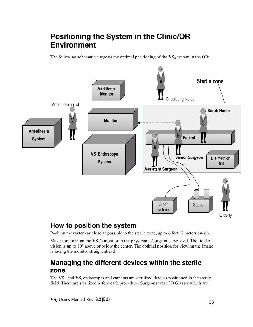
Positioning the System in the Clinic/OR Environment The following schematic suggests the optimal positioning of the VS3 system in the OR:
How to position the system Position the system as close as possible to the sterile zone, up to 6 feet (2 meters away).
Make sure to align the VS3’s monitor to the physician’s/surgeon’s eye level. The field of vision is up to 10° above or below the center. The optimal position for viewing the image is facing the monitor straight ahead.
Managing the different devices within the sterile zone The VSII and VS3 endoscopes and cameras are sterilized devices positioned in the sterile field. These are sterilized before each procedure. Surgeons wear 3D Glasses which are
Patient
VS3 Endoscope System
Monitor
Additional Monitor
X
Anesthesia System
X
X
X
Circulating Nurse
Scrub Nurse
Senior Surgeon
Assistant Surgeon
Orderly
Anesthesiologist
X
X
Sterile zone
Suction
Disinfection Unit
Other systems
VS3 User's Manual Rev. 8.2 (EU)
34
placed on them by a non-sterile nurse (same procedure as protective glasses or loops). These are passive 3D glasses that do not require any further adjustments once placed.
The end side of the sterile cable of the 3D camera is handed over to a non-sterile nurse to be plugged into the non-sterile system. The orderly or circulating nurse opens the cap so that the connector won’t contaminate the sterile zone.
Temperature and Lighting Room temperature – Per institutional protocol.
Ambient lighting - The recommended illumination of the room should be as minimal as possible. For best results, set one light source over the work table, and set an additional light source over the anesthesiologist’s working area (if applicable).

VS3 User's Manual Rev. 8.2 (EU)
35
Using the VS3 System
Chapter Four
VS3 User's Manual Rev. 8.2 (EU)
36
Using the VS3 Endoscopes is straightforward and no different than using a standard endoscope. The VS3 Iridium scope is used like a miniature microscope in that it is connected to the camera and positioned 20cm to 45cm above the patient to display the surgical scene.
The console features a Camera Control Unit (CCU) and uses an advanced stereoscopic monitor, which when viewed with polarizing glasses, provides full 3D depth perception on-screen. This innovative capability enhances the physician’s/surgeon’s ability to make real-time diagnostic and procedural/surgical decisions during the endoscopic procedure. In addition, the VS3 Endoscope provides comprehensive recording and data management features.
Using the endoscope in this way involves just a few simple steps:
1. Connect up the system. (Optional) Connect a secondary stereo or monocular monitor.
2. Use the endoscope in the procedure.
3. Disconnect the endoscope and shut down the system.
The VS3 system also provides the following special features:
x Select image preferences.
x Flip the image.
x Change the image size
x Record the procedure video
x Take snapshots of the procedure.
x Download the recorded data to a removable storage device.
x View the recordings of the procedure.
Some of these features may be used while the camera is connected, while other features may only be used while the camera is disconnected from the system. Generally, you can only view the recordings of the procedure while the camera is disconnected.
Using Visionsense follows the normal cycle of a surgical procedure
Special Features
VS3 User's Manual Rev. 8.2 (EU)
37
Starting and Running the Visionsense Stereoscopic Endoscope System The following procedures provide instructions for using the VS3 Endoscope as a standard endoscopic system. These instructions assume that you have already followed the instructions in Chapter 3 for preparation and sterilization of the equipment.
Step 1: Connecting Up the VS3 System Before you can use the VS3 Endoscope, you must connect the system modules to each other and to a power source. Follow the steps here to connect and verify that the system is ready for use.
To connect up the VS3 System for an endoscopic procedure: 1. Connect the system to an external power source.
2. (Optional) If using a secondary monitor, see to connect a secondary monitor section on page 41.
3. Turn on the VS3 System by pressing the ON/OFF button. A green LED lights up to indicate the system is on.
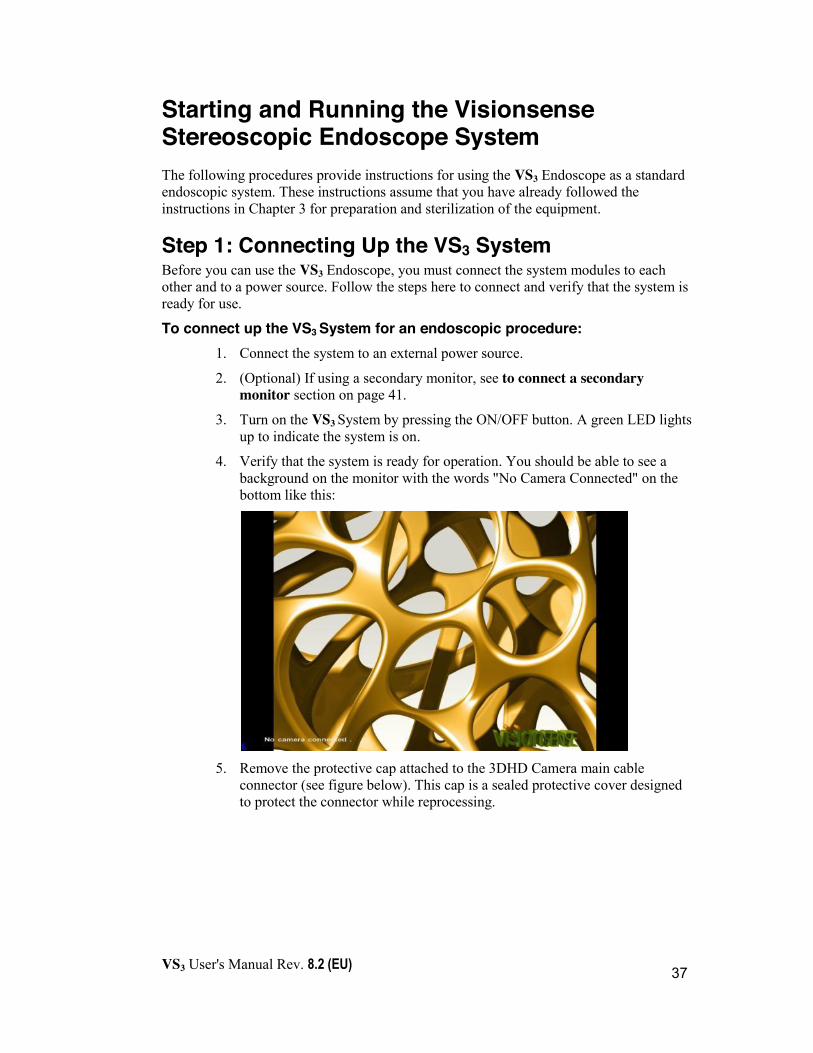
4. Verify that the system is ready for operation. You should be able to see a background on the monitor with the words "No Camera Connected" on the bottom like this:
5. Remove the protective cap attached to the 3DHD Camera main cable
connector (see figure below). This cap is a sealed protective cover designed to protect the connector while reprocessing.

VS3 User's Manual Rev. 8.2 (EU)
38
Cautions
x Do not detach the protective cap from the unit.
x Do not pull on the cable connected to the camera.
6. Connect the 3DHD Camera cable to the camera port on the Camera Control Unit (CCU). Make sure to align the red dot on the camera connector with the red stripe on the system port. (The red dot should be facing up when connected to the CCU.):
(For the optional VSII Endoscope, connect in a similar manner to the port adjacent to the VS3 connection port on the CCU.)
Warnings
x The connector to the system is non-sterile.
x Do not connect both VSII and VS3 cameras together. An error message will appear on the screen and live image will be blocked in such a case.
x Do not insert any other endoscope or illumination unit other than the one provided with the system.
PHD Camera
!
!
VS3 User's Manual Rev. 8.2 (EU)
39
x Do not perform procedures without the provided polarizing glasses.
x Do not operate with a camera that is not recognized by the system (an on-screen message alerts you to this).
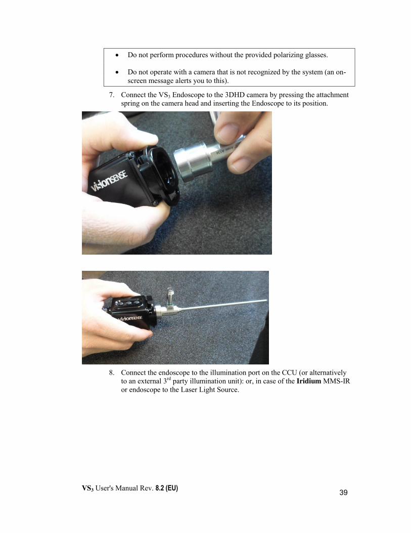
7. Connect the VS3 Endoscope to the 3DHD camera by pressing the attachment spring on the camera head and inserting the Endoscope to its position.
8. Connect the endoscope to the illumination port on the CCU (or alternatively
to an external 3rd party illumination unit): or, in case of the Iridium MMS-IR or endoscope to the Laser Light Source.
VS3 User's Manual Rev. 8.2 (EU)
40
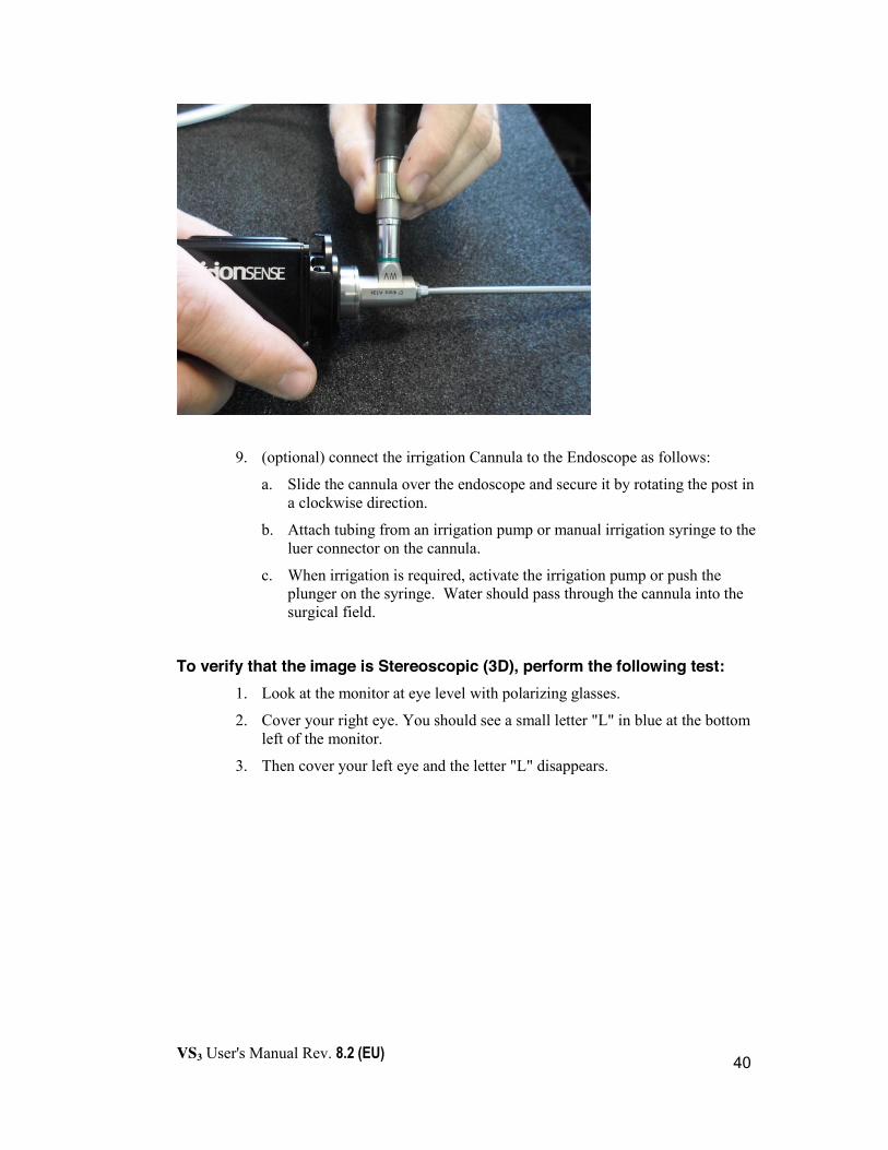
9. (optional) connect the irrigation Cannula to the Endoscope as follows:
a. Slide the cannula over the endoscope and secure it by rotating the post in a clockwise direction.
b. Attach tubing from an irrigation pump or manual irrigation syringe to the luer connector on the cannula.
c. When irrigation is required, activate the irrigation pump or push the plunger on the syringe. Water should pass through the cannula into the surgical field.
To verify that the image is Stereoscopic (3D), perform the following test: 1. Look at the monitor at eye level with polarizing glasses.
2. Cover your right eye. You should see a small letter "L" in blue at the bottom left of the monitor.
3. Then cover your left eye and the letter "L" disappears.

VS3 User's Manual Rev. 8.2 (EU)
41
To connect a secondary stereo monitor or a monocular monitor (optional): Verify the system is shut down before performing the following steps.
1. Connect the secondary monitor cable connector to the secondary monitor DVI connector port on the back of the CCU:
Figure 9: Back of CCU
2. Turn on the monitor.
3. Turn on the system.
Step 2: Using the VS3 Endoscope System To use the 3D Endoscope during a procedure:
1. Put on the polarizing glasses provided with the system (they will provide the depth perception).
2. Use the endoscope as you would operate any other endoscope.
Step 3: Shutting Down the System After finishing the procedure, shut down the system as follows:
1. Press the ON/OFF button located on the front left side of the CCU.
The following message appears:
2. Press the ON/OFF button again to shut down the system.
3. Disconnect the camera main cable from the system by pulling back the camera connector sleeve until fully retracted and then pulling the cable.
4. Close the camera connector’s protective cover.
Please press again to shut down the system.
USB ports
Main Monitor Secondary Monitor
ON/OFF Power switch
Power Supply Socket
Communication port
1 2
VGA port
VS3 User's Manual Rev. 8.2 (EU)
42
5. Promptly deliver the camera to your authorized personnel for cleaning, sterilization, and storage. The authorized personnel will sterilize the camera in compliance with institutional protocols.
6. Disconnect the system from the external power source.
Cautions
x Do not disconnect the system from the external power source without a proper shutdown.
!
VS3 User's Manual Rev. 8.2 (EU)
43
To Use VS3 Iridium with IR Fluorescence Dye VS3 Iridium is designed to work with an approved IR fluorescence dye (principally ICG) which has excitation at 805nm and emission band between 825nm and 850nm. VS3 Iridium provides excitation light to the surgical field to excite the dye molecules and captures emission from the dye using an IR sensitive camera.
Please follow applicable dye manufacturer recommendations for dosage and of the dye.
To use the VS3 Iridium for fluorescence imaging: 1. Attach the Iridium scope to a scope holding arm or take the scope in hand to
position over the patient. The VS3 system will automatically detect the scope and format the screen display to show 3 images as demonstrated in Figure 10 below. The images are:
a. IR image showing fluorescence
b. False color IR image which assigns colors to IR intensity bands
c. Fused image showing the visible light image with an IR overlay
2. If Using the Iridium MMS-IR, position the scope 20cm to 40cm above the surgical field. Looking at the system monitor, adjust the scope position to provide the required field of view. The Iridium endoscope should be used the same way as a conventional endoscope.
3. (OPTIONAL) Enter study parameters using the following procedure
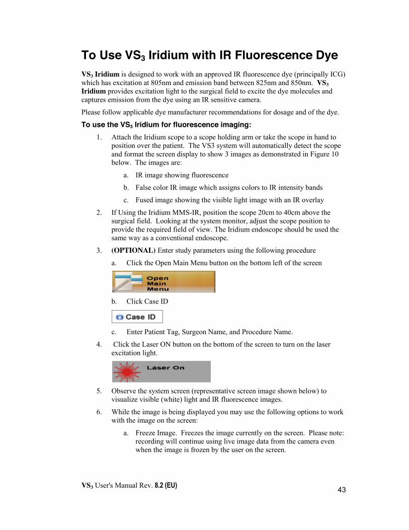
a. Click the Open Main Menu button on the bottom left of the screen
b. Click Case ID
c. Enter Patient Tag, Surgeon Name, and Procedure Name.
4. Click the Laser ON button on the bottom of the screen to turn on the laser excitation light.
5. Observe the system screen (representative screen image shown below) to
visualize visible (white) light and IR fluorescence images.
6. While the image is being displayed you may use the following options to work with the image on the screen:
a. Freeze Image. Freezes the image currently on the screen. Please note: recording will continue using live image data from the camera even when the image is frozen by the user on the screen.

VS3 User's Manual Rev. 8.2 (EU)
44
b. Swap Image Order. Change the order of the IR, IR Color and Fused
images on the screen (refer to Figure 10 below).
c. Move the mouse to position the cursor over one of the images on the
screen. When the cursor is moved over the image a small window next to the cursor displays the absolute intensity of the IR signal at that position on the screen (0..255) and a relative intensity (%) of the current position’s IR signal.
The relative intensity is computed relative to a Base Point. The Base Point should be set by the user to the area used as a reference. If the Base Point has not been defined, the system will automatically set an Auto Base Point to the brightest area in the image.
d. Click the Set Base Point button to set the Base Point which will be used as a reference value for all User Points (see below). After clicking the Set Base Point button, move the cursor to the location that you wish to use as a Base Point and click the left mouse button.
e. Click anywhere in the image to set a User Point. A User Point
maintains the display of the absolute and relative intensities after the mouse is moved. If a live image is being observed, the values of intensity in the user points will change as the underlying image changes.
VS3 User's Manual Rev. 8.2 (EU)
45
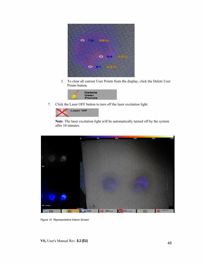
f. To clear all current User Points from the display, click the Delete User
Points button.
7. Click the Laser OFF button to turn off the laser excitation light.
Note: The laser excitation light will be automatically turned off by the system after 10 minutes.
Figure 10 Representative Iridium Screen

VS3 User's Manual Rev. 8.2 (EU)
46
Using VS3’s Special Features The VS3 system provides advanced features that permit customizing the stereoscopic image attributes, recording the procedure, moving recorded data to a removable storage device and viewing the recorded data. To perform these tasks, you use the control buttons and the VS3 menu options displayed on the monitor as shown below.
Note: Different menus are displayed depending on whether or not a camera is connected to the system.
Where Control Buttons are mentioned, they refer to either the touchpad\mouse buttons or the camera buttons which perform identical actions.
Using the Endoscope and Touchpad\Mouse Buttons The VS3 system has control buttons accessible on the VS3 Camera in the sterile field to enable quick use during the procedure. Alternatively, you can use the touchpad on the keyboard to scroll to and select a menu item, and to operate the camera. You can optionally attach a mouse for the same purpose. The following figure shows the actions performed by the camera buttons and mouse buttons when a mouse is used:
Note: Using the Keyboard When using the keyboard and touchpad the following keyboard keys correspond to the middle mouse button:
s: takes a snapshot
b: displays the software version
i

VS3 User's Manual Rev. 8.2 (EU)
47
Recording the Procedure The VS3 enables easy recording of an endoscopic procedure video.
Recordings can be transferred to a removable storage device (USB flash memory or an external hard drive). The recordings are available for viewing after a procedure, as either a stereo movie or a mono movie. Stereo movies may be viewed using the VS3 System or any movie player supporting stereo video. When using a 2D personal computer or laptop to play a movie, the image will be seen in mono.
A recording can be stopped/started at any time during the procedure.
To record a procedure: x During the procedure, click the Proximal Camera Button or right
mouse/touchpad button. At the top left corner of the monitor, an icon with a time indicator is displayed, indicating that the recording is taking place.
System’s capacity is approx. 24H of recorded videos. New recordings will delete and replace the oldest recorded data.
Therefore, it is recommended to download the recorded data to a removable storage device key to prevent data loss. See Managing Recordings section on page 49.
To stop the recording: x Click the Proximal Button or the right mouse/touchpad button again to stop
recording (the icon will disappear from the screen). The recorded file is temporarily saved in the system.
See section entitled Managing Recordings on page 49 to learn how to save recorded data onto a removable storage device.
Caution
x Recordings cannot be viewed while a camera is connected to the system.
i
!

VS3 User's Manual Rev. 8.2 (EU)
48
Taking a Snapshot of the Procedure The VS3 System enables taking snapshots of surgical procedures. A snapshot is defined as making a temporary copy of one selected image (like a photograph). Like recordings, snapshots of procedures can be used in a variety of ways, including educational purposes and demonstrations at professional presentations and conferences.
To take a snapshot of a procedure:
x During the procedure, click the camera Middle Control Button, press ‘s’ on the keyboard, or click the mouse middle button. A white frame will flash on the image, indicating that the snapshot has been taken.
See section entitled Copying to a USB on page 52 to learn how to save recorded data onto a removable storage device.
Menu options when no camera is connected to the system When there is no camera connected to the system, the surgeon can view recordings of previous procedures. Options for Maintenance and Service of the system are also displayed, but available only to Visionsense personnel. The menu looks like this:
The options are as follows:
Back Click on Back at any time to exit the Main Menu.
Please note: the menu will automatically close after 10 seconds of inactivity.

VS3 User's Manual Rev. 8.2 (EU)
49
Managing Recordings The VS3 System enables the surgeon to store as well as view recordings of previous procedures. The surgeon can control the playback of the recording, as well as perform management activities such as backing up the recording to a USB device.
The VS3 System allows you to store up to 24 hours of recordings. After using up 24 hours of content, the system will overwrite oldest recordings with new video. If this happens, the old recordings will not be accessible. For this reason, it is crucial to periodically download recordings to a removable storage device.
To access the Manage Recordings screen, from the Main Menu, choose Manage Recordings – the following screen is displayed:
Playing a recording You can play films of previously recorded procedures.
To play a film: 1. In the File Browser (left pane), browse the folders and files until you locate
the movie that you want to play.
2. Select the movie and click the Play button on the control panel (lower right pane) to play the film:

VS3 User's Manual Rev. 8.2 (EU)
50
Using the Control Panel Use the control panel to control the playback of the film as follows:
Button Function Keyboard Shortcut
Play/Pause ‘Space’
Stops the movie and returns you to the beginning of the movie. (None)
Previous/Next Movie ‘<’ / ‘>’
Decrease/Increase speed of playback. Each click increases/decreases in increments of 0.25, from 0.25x to 2.0x.
‘+’ / ‘-‘
Toggles between 2D and 3D view.
‘2’
Toggles between full screen and regular display. ‘F’
Play Bar The elapsed time of the movie is displayed near the Play bar as shown below. You can use the slider on the Play bar to jump to various parts in the movie:

VS3 User's Manual Rev. 8.2 (EU)
51
Working with Iridium Fluorescence Video during Playback You can work with the fluorescence video during playback in a way similar to live video available during the procedure. Specifically, the following functions are available during playback of fluorescence video
a. Swap Image Order. Change the order of the IR, IR False Color and Fused images on the screen. This allows you to select which image will be in the larger window on the right and which two images will be in small windows on the left. By default, the Fused image is in the large window on the right.
b. Move the mouse to position the cursor over one of the images on the screen. When
the cursor is moved over the image, a small window next to the cursor displays the absolute intensity of the IR signal at that position on the screen (0.255) and a relative intensity (%) of the current position’s IR signal.
The relative intensity is computed relative to a Base Point. The Base Point should be set by the user to the area used as a reference. If the Base Point has not been defined, the system will automatically set an Auto Base Point to the brightest area in the image.
c. Click the Set Base Point button to set the Base Point, which will be used as a
reference value for all User Points (see below). After clicking the Set Base Point button, move the cursor to the location that you wish to use as a Base Point and click the left mouse button.
d. Click anywhere in the image to set a User Point. A User Point maintains the display
of the absolute and relative intensities after the mouse is moved. The values of intensity in the user points will change as the video is being played.

VS3 User's Manual Rev. 8.2 (EU)
52
e. To clear all current User Points from the display click the Delete User Points button
Playing an Entire Folder You can play an entire folder of movies by clicking the Play Folder button .
below the right File Browser pane. After the first movie plays, the player consecutively plays each movie in the folder's list of files.
You can stop the playback at any time by clicking the Stop Playback button .
Close Click the Close button below the Browser pane to exit the Manage Recordings window and return to the Main menu.
Copying to a USB Device You can make a copy of the movies or snapshots taken during a procedure by moving them to a removable storage device. For more details regarding downloading of recordings, see Managing Recordings section on page 49.
To copy to a USB: 1. Insert a USB device into one of the computer's USB ports (located in the front and
in the back of the CCU).
2. From the Browser pane, select the movie, or folder of movies, that you want to copy.
3. Click the Copy to USB button located underneath the Browser pane.

VS3 User's Manual Rev. 8.2 (EU)
53
Viewing a Recorded Movie or Snapshot Stored on a USB
1. Movies and snapshots recorded using the VS3 and which were downloaded onto a removable storage device can be played back directly from that storage device.
2. The movie or snapshot of the recorded procedure is displayed on the stereoscopic monitor.
3. A single movie or all of the available movies can be played sequentially.
As a safety precaution, a movie or snapshot cannot be played back as long as a camera is connected to the system.
Caution
x Before viewing the movie or snapshot in 3D, make sure that you are wearing the provided polarizing glasses.
Deleting Movie Files You cannot delete movie files. Deleting movie files can only be performed by a Visionsense Technician.
i
!

VS3 User's Manual Rev. 8.2 (EU)
54
Menu options with Camera Connected to a VS3 Stereoscopic endoscope When the camera is connected to the system, the screen and Main menu look like this:
Until you connect the endoscope to the camera, a No scope connected.. message is displayed at the bottom of the screen.
When the camera is connected to the system, you can perform the following:
Ó Use the Main menu options to control the image size, rotation, 3D/2D display, and image quality factors.
Ó Use the buttons on the camera to record a procedure, or take a snapshot.
White Balance Click on White Balance in the Main Menu to while pointing the endoscope at a pure white surface located approximately 3cm from the tip of the endoscope to color balance the camera.
Important: White Balance should be done every time you change endoscopes.
Rotating (Flipping) the Image You can flip the image horizontally by clicking Rotate/Flip from the Main menu.
i
i
VS3 User's Manual Rev. 8.2 (EU)
55
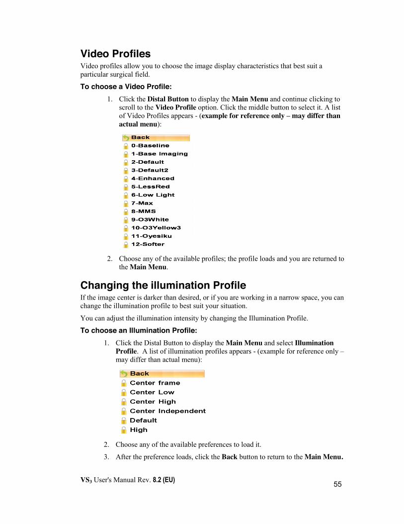
Video Profiles Video profiles allow you to choose the image display characteristics that best suit a particular surgical field.
To choose a Video Profile: 1. Click the Distal Button to display the Main Menu and continue clicking to
scroll to the Video Profile option. Click the middle button to select it. A list of Video Profiles appears - (example for reference only – may differ than actual menu):
2. Choose any of the available profiles; the profile loads and you are returned to
the Main Menu.
Changing the illumination Profile If the image center is darker than desired, or if you are working in a narrow space, you can change the illumination profile to best suit your situation.
You can adjust the illumination intensity by changing the Illumination Profile.
To choose an Illumination Profile: 1. Click the Distal Button to display the Main Menu and select Illumination
Profile. A list of illumination profiles appears - (example for reference only – may differ than actual menu):
2. Choose any of the available preferences to load it.
3. After the preference loads, click the Back button to return to the Main Menu.

VS3 User's Manual Rev. 8.2 (EU)
56
Zoom You can enlarge the image that you are viewing by choosing Zoom from the Main Menu. The following display appears:
To zoom in and out of the image, click the distal and proximal buttons on the endoscope (or left and right buttons of the mouse). The zoom increments/decrements by intervals of 0.1, from x1 to x2.
Brightness This feature allows you to control the brightness of the image directly. By default, the brightness is set to 0.0 and can be increased or decreased.
Contrast This feature allows you to control the contrast of the image directly. By default, the contrast is set to 0.0 and can be increased or decreased.
Case ID You can use Case ID to associate with the folder that will contain the subsequent movies or snapshot that you wish to record. All subsequent movies and snapshots will be saved in the specified folder until you use Case ID to specify a new name.
To specify a new name: 1. From the Main Menu, choose Case ID. The following screen appears:

VS3 User's Manual Rev. 8.2 (EU)
57
2. Using the touchpad, click Back on the on-screen keyboard repeatedly to
erase the displayed name.
3. Using the touchpad, click the appropriate keys on the on-screen keyboard to type the new name.
4. Click the green check to apply the changes. All subsequent movies and snapshots will be saved in the specified folder.
Image Size The physician/surgeon can change the size of the image on the screen:
x Increase will increase the image up to full screen on the main or second monitor.
x Decrease will decrease the size down to a preset minimal size on the main or second monitor.
Important - The saved settings become the default for next system restart.
x When using 24” secondary monitor, the changes set for the main monitor are set automatically to the second monitor respectively. The second screen cannot be set independently.
x When using 46” secondary monitor, the changes are set to each monitor independently.
Switch to 2D Allows you to toggle between 2D and 3D view.
VS3 User's Manual Rev. 8.2 (EU)
58
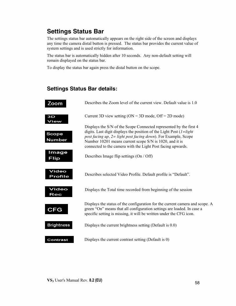
Settings Status Bar The settings status bar automatically appears on the right side of the screen and displays any time the camera distal button is pressed. The status bar provides the current value of system settings and is used strictly for information.
The status bar is automatically hidden after 10 seconds. Any non-default setting will remain displayed on the status bar.
To display the status bar again press the distal button on the scope.
Settings Status Bar details:
Displays the current brightness setting (Default is 0.0)
Displays the current contrast setting (Default is 0)
Displays the status of the configuration for the current camera and scope. A green “On” means that all configuration settings are loaded. In case a specific setting is missing, it will be written under the CFG icon.
Displays the Total time recorded from beginning of the session
Describes selected Video Profile. Default profile is “Default”.
Describes Image flip settings (On / Off)
Displays the S/N of the Scope Connected represented by the first 4 digits. Last digit displays the position of the Light Post (1=light post facing up, 2= light post facing down). For Example, Scope Number 10201 means current scope S/N is 1020, and it is connected to the camera with the Light Post facing upwards.
Current 3D view setting (ON = 3D mode, Off = 2D mode)
Describes the Zoom level of the current view. Default value is 1.0

VS3 User's Manual Rev. 8.2 (EU)
59
Maintenance of the VS3 System
Chapter Five
VS3 User's Manual Rev. 8.2 (EU)
60
Changing the Endoscope and/or Camera If the endoscope or the camera becomes contaminated, it is necessary to replace the endoscope or camera with another stand-by device that has been installed for the VS3 System and is sterilized. See Installing a new endoscope below.
To change an Endoscope, follow these steps: 1. Press the camera attachment spring to release the Endoscope.
2. Detach the endoscope and release the attachment spring of the camera.
3. Press the attachment spring on the camera again.
4. Insert the new (installed) Endoscope into its position
5. Continue with the procedure.
To change a camera, follow these steps:
1. Disconnect the old camera by pulling back the camera connector sleeve until fully retracted and then pulling the cable.
2. Replace the cap to the connector end.
3. Unscrew the cap off the new camera connector.
4. Connect the new camera.
5. Continue with the procedure.
Installing a new endoscope for the first time Initial installation is required when receiving a new endoscope from Visionsense. It will be supplied with a USB flash device containing the configuration files for the endoscope. This process needs to be done only once for each system the endoscope is used with.
To install a new endoscope: 1. Connect the endoscope files USB flash device to the system. Make sure the
camera is not connected when you connect the endoscope USB flash drive.
2. Click the left touchpad/mouse button to activate the Main Menu.
3. In the Main Menu, select “Service”.
4. In the Service menu, select “Execute Maintenance Script From USB”. A “quiet” installation will take place.
5. When installation is complete, the message "Camera configuration installed successfully" will appear.

VS3 User's Manual Rev. 8.2 (EU)
61
The new endoscope is now installed and ready for use.
Caution
x Do not connect the camera before you connect the USB device and install the files.
!

VS3 User's Manual Rev. 8.2 (EU)
62
VS3 Modules and Parts
Chapter Six
VS3 User's Manual Rev. 8.2 (EU)
63
System Console The System Console consists of the Camera Control Unit (CCU), Cart and illumination unit.
Camera Control Unit (CCU) The camera control unit is contains the system’s hardware and software required to operate the system.
Input voltage 120 VAC or 230 VAC
Input frequency 50Hz@230VAC or 60Hz@120VAC
Max power consumption 1300VA
Storage Humidity 90%
Operating Humidity 15% to 80% at 35º C
Storage Temperature -40º C to 70º C
Operating Temperature 10º C to 35º C
Altitude
Operating: 0 to 3,042m
Non-operating: 0 to 4,572m
Display Unit (Primary Monitor) The surgical procedure is viewed on the primary monitor which is connected to the System Console. The primary monitor is a Sony 24” stereoscopic display, approved for use in the operating room. An optional 32” Sony monitor is available.
Polarizing Eye Glasses Polarizing eye glasses enables stereoscopic vision while conducting a surgical procedure. The glasses can be worn on top of regular eye glasses.
Secondary Monitor (optional) A secondary monitor (stereo or monocular) can be added for extra viewing or educational purposes. A DVI cable is required to connect the secondary monitor.
VSII Endoscope (optional) The VSII Endoscope provides the physician with natural stereoscopic vision while conducting a surgical procedure. The VSII Endoscope is a fully self-contained device with an integrated distal chip camera and LED light source.

VS3 User's Manual Rev. 8.2 (EU)
64
Storage Temperature: -10º C to 70º C; Storage Humidity: 90%
VS3 Endoscope & Camera The VS3 Stereoscopic High Definition System consists of separate VS3 Camera and VS3 Endoscope units providing the physician with natural stereoscopic vision with enhanced image definition and focus control.
Storage Temperature: -10º C to 70º C; Storage Humidity: 90%
Accessories Cannula (optional) You can use a cannula along with the endoscope to keep the endoscope lens clear of debris thereby maintaining maximum vision during a procedure.
VS3 Iridium Scope The VS3 Iridium scope is providing the physician with capability to view IR fluorescence and visible light images.
VS3 Laser Light Source The VS3 Iridium laser light source produces the 805nm excitation light necessary to excite fluorescent dye molecules in the surgical field to produce fluorescence.
System Power Consumption Maximum total power consumption 1300W (may be less dependent on display configuration).
Equipment Labels, Symbols, Warning Statements and Abbreviations
Symbol Explanation
Ethernet port
USB Removable Disk port
3D Stereo Monitor (3D)
Camera connection port

VS3 User's Manual Rev. 8.2 (EU)
65
Symbol Explanation
On / Off Button
A134°c Autoclave Approved Camera ID - marked on shaft
Caution, consult accompanying documents
Type "BF" EN 60601-1
Date of manufacturing
Separate collection for electrical and electronic equipment, recycling do not dispose into normal waste stream
CE marking of conformity 93/42/EEC & MDD 2007/47
Certified to CSA Std. C22.2 No 601.1 Conforms to UL Std 60601-1
VS3 Console Label (120V)
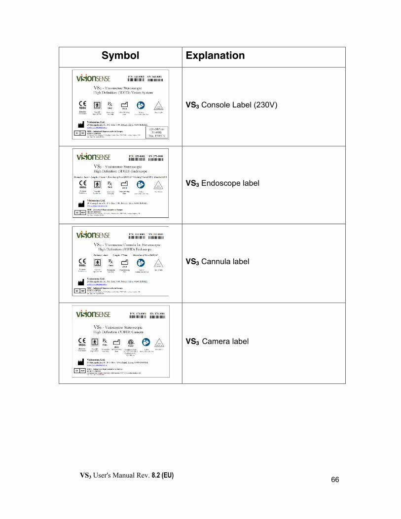
VS3 User's Manual Rev. 8.2 (EU)
66
Symbol Explanation
VS3 Console Label (230V)
VS3 Endoscope label
VS3 Cannula label
VS3 Camera label

VS3 User's Manual Rev. 8.2 (EU)
67
Symbol Explanation
VS3 Coupler for 2D Endoscopes label
VS3 Iridium Scope label
VS3 Iridium Laser Illumination Unit label
VS3 Iridium Laser light source labels
VISIBLE AND INVISIBLE LASER RADIATIONAVOID DIRECT EYE EXPOSURE
CLASS 3R LASER PRODUCT
Device classified per IEC 60825-1:2007
Maximum Output: 60 mW at wavelength: 650nmMaximum Output: 3000 mW at wavelength: 805nm

VS3 User's Manual Rev. 8.2 (EU)
68
List of VS3 Endoscopes and Accessories
Device/Accessories Name Device Part
Number (P/N)
Printing on Endoscope
Ring Color
Endoscope 4mm, Short, 0°, Standard FOV 153-0001 S/N + SV Green Endoscope 4mm, Short, 30°, Standard FOV 153-0002 S/N + SV Red Endoscope 4mm, Short, 0°, Wide FOV 153-0003 S/N + WV Green Endoscope 4mm, Short, 30°, Wide FOV 153-0004 S/N +WV Red Endoscope 4mm, Short, 0°, Extended FOV 153-0005 S/N + EV Green Endoscope 4mm, Elbow, Short, 0°,Wide FOV 153-0006 S/N + WV Green Endoscope 4mm, Long, 0°, Standard FOV 153-0011 S/N + SV Green Endoscope 4mm, Long, 30°, Standard FOV 153-0012 S/N + SV Red Endoscope 4mm, Long, 0°, Wide FOV 153-0013 S/N +WV Green Endoscope 4mm, Long, 30°, Wide FOV 153-0014 S/N +WV Red Endoscope 5.5mm, Short, 0°, Standard FOV 153-0021 S/N + SV Green Endoscope 5.5mm, Short,30°, Standard FOV 153-0022 S/N + SV Red Endoscope 5.5mm, Short, 0°, Wide FOV 153-0023 S/N +WV Green Endoscope 5.5mm, Short, 30°, Wide FOV 153-0024 S/N +WV Red Endoscope 5.5mm, Long, 0°, Standard FOV 153-0031 S/N + SV Green Endoscope 5.5mm, Long, 30°, Standard FOV 153-0032 S/N + SV Red Endoscope 5.5mm, Long, 0°, Wide FOV 153-0033 S/N +WV Green Endoscope 5.5mm, Long, 30°, Wide FOV 153-0034 S/N +WV Red ETV Endoscope 6mm, Short, 0°, Wide FOV 153-0041 S/N +WV Green Endoscope-IR 5.5mm, Long, 0°,Standard FOV 153-0051 S/N +SV Green Endoscope-IR 5.5mm, Long,30°,Standard FOV 153-0052 S/N +SV Red Cannula 4mm, Short, 0° 114-0001 S/N Green Cannula 4mm, Short, 30° 114-0002 S/N Red Cannula 4mm, Long, 0° 114-0011 S/N Green Cannula 4mm, Long, 30° 114-0012 S/N Red Cannula 5.5mm, Short, 0° 114-0021 S/N Green Cannula 5.5mm, Short, 30° 114-0022 S/N Red Cannula 5.5mm, Long, 0° 114-0031 S/N Green Cannula 5.5mm, Long, 30° 114-0032 S/N Red High Definition Stereoscopic (3DHD) Camera 174-0001 S/N N/A Iridium Miniature Microscope (MMS-IR) 174-0012 S/N N/A Coupler for 2D Endoscopes (“2D Coupler”) 174-0020 S/N N/A Coupler for Large 2D Endoscopes (“2D Coupler Large”)
174-0021 S/N N/A
Iridium High Definition Camera (Camera-IR) 174-0051 S/N N/A

VS3 User's Manual Rev. 8.2 (EU)
69
List of VSII Cameras and Cannulas
Device/Accessories Name Device Part Number (P/N)
Label on Cable
Buttons Color
Camera Rigid, Short, Standard View, 0° 172-0030 S/N Black Camera Rigid, Short, Standard View, 30° 172-0031 S/N Black Camera Rigid, Long, Standard View, 0° 172-0032 S/N Black Camera Rigid, Long, Standard View, 30° 172-0033 S/N Black Camera Rigid, Short, Wide View, 0° 172-0070 S/N Orange Camera Rigid, Short, Wide View, 30° 172-0071 S/N Orange Camera Rigid, Long, Wide View, 0° 172-0072 S/N Orange Camera Rigid, Long, Wide View, 30° 172-0073 S/N Orange Camera Rigid, Short, Standard View, 0°,Demo 172-0040 S/N + DEMO Black Camera Rigid, Short ,Standard View,30°,Demo 172-0041 S/N + DEMO Black Camera Rigid, Long, Standard View, 0°, Demo 172-0044 S/N + DEMO Black Camera Rigid, Long, Standard View, 30°,Demo 172-0045 S/N + DEMO Black Camera Rigid, Short, Wide View, 0°, Demo 172-0080 S/N + DEMO Orange Camera Rigid, Short, Wide View, 30°, Demo 172-0081 S/N + DEMO Orange Camera Rigid, Long, Wide View, 0°, Demo 172-0082 S/N + DEMO Orange Camera Rigid, Long, Wide View, 30°, Demo 172-0083 S/N + DEMO Orange Camera Rigid, Short, Standard View, 0°, Autoclaveable
172-0230 S/N Black
Camera Rigid, Short , Standard View, 30°, Autoclaveable
172-0231 S/N Black
Camera Rigid, Long, Standard View, 0°, Autoclaveable
172-0232 S/N Black
Camera Rigid, Long, Standard View, 30°, Autoclaveable
172-0233 S/N Black
Camera Rigid, Short, Wide View, 0°, Autoclaveable
172-0270 S/N Orange
Camera Rigid, Short, Wide View, 30°, Autoclaveable
172-0271 S/N Orange
Camera Rigid, Long, Wide View, 0°, Autoclaveable
172-0272 S/N Orange
Camera Rigid, Long, Wide View, 30°, Autoclaveable
172-0273 S/N Orange
Camera Rigid, Short, Standard View, 0°, Demo, Autoclaveable
172-0240 S/N + DEMO Black
Camera Rigid, Short , Standard View, 30°,Demo, Autoclaveable
172-0241 S/N + DEMO Black
Camera Rigid, Long, Standard View, 0°, Demo, Autoclaveable
172-0242 S/N + DEMO Black
Camera Rigid, Long, Standard View, 30°, Demo, Autoclaveable
172-0243 S/N + DEMO Black
Camera Rigid, Short, Wide View, 0°, Demo, Autoclaveable
172-0280 S/N + DEMO Orange
Camera Rigid, Short, Wide View, 30°, Demo, 172-0281 S/N + DEMO Orange

VS3 User's Manual Rev. 8.2 (EU)
70
Device/Accessories Name Device Part Number (P/N)
Label on Cable
Buttons Color
Autoclaveable Camera Rigid, Long, Wide View, 0°, Demo, Autoclaveable
172-0282 S/N + DEMO Orange
Camera Rigid, Long, Wide View, 30°, Demo, Autoclaveable
172-0283 S/N + DEMO Orange
Camera Rigid, Short, Standard View, 0°, Not for Human Use
172-0042 S/N + N4HU Black
Camera Rigid, Short , Standard View, 30°, Not for Human Use
172-0043 S/N + N4HU Black
Camera Rigid, Long, Standard View, 0°, Not for Human Use
172-0046 S/N + N4HU Black
Camera Rigid, Long, Standard View, 30°, Not for Human Use
172-0047 S/N + N4HU Black
Camera Rigid, Short, Wide View, 0°, Not for Human Use
172-0084 S/N + N4HU Orange
Camera Rigid, Short, Wide View, 30°, Not for Human Use
172-0085 S/N + N4HU Orange
Camera Rigid, Long, Wide View, 0°, Not for Human Use
172-0086 S/N + N4HU Orange
Camera Rigid, Long, Wide View, 30°, Not for Human Use
172-0087 S/N + N4HU Orange
Cannula for Camera Rigid Short, 0° 110-0003 N/A N/A Cannula for Camera Rigid Short, 30° 110-0004 N/A N/A Cannula for Camera Rigid Long, 0° 110-0005 N/A N/A Cannula for Camera Rigid Long, 30° 110-0008 N/A N/A Camera Flexible, Standard View , 0° 173-0030 S/N Black Camera Flexible, Wide View, 0° 173-0070 S/N Orange Camera Flexible, Standard View , 0°, Demo 173-0040 S/N + DEMO Black Camera Flexible, Wide View, 0°, Demo 173-0080 S/N + DEMO Orange Micro Holder for Flexible Endoscope 113-0001 N/A N/A Hand Holder for Flexible Endoscope 113-0002 N/A N/A

VS3 User's Manual Rev. 8.2 (EU)
71
Troubleshooting
Chapter Seven
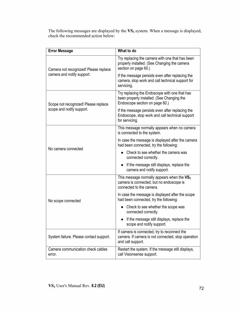
VS3 User's Manual Rev. 8.2 (EU)
72
The following messages are displayed by the VS3 system. When a message is displayed, check the recommended action below:
Error Message What to do
Camera not recognized! Please replace camera and notify support.
Try replacing the camera with one that has been properly installed. (See Changing the camera section on page 60.) If the message persists even after replacing the camera, stop work and call technical support for servicing.
Scope not recognized! Please replace scope and notify support.
Try replacing the Endoscope with one that has been properly installed. (See Changing the Endoscope section on page 60.) If the message persists even after replacing the Endoscope, stop work and call technical support for servicing.
No camera connected
This message normally appears when no camera is connected to the system. In case the message is displayed after the camera had been connected, try the following: z Check to see whether the camera was
connected correctly. z If the message still displays, replace the
camera and notify support.
No scope connected
This message normally appears when the VS3 camera is connected, but no endoscope is connected to the camera. In case the message is displayed after the scope had been connected, try the following: z Check to see whether the scope was
connected correctly. z If the message still displays, replace the
scope and notify support.
System failure. Please contact support. If camera is connected, try to reconnect the camera. If camera is not connected, stop operation and call support.
Camera communication check cables error.
Restart the system. If the message still displays, call Visionsense support.
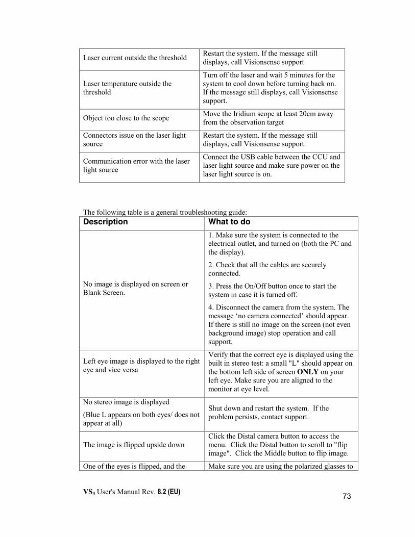
VS3 User's Manual Rev. 8.2 (EU)
73
Laser current outside the threshold Restart the system. If the message still displays, call Visionsense support.
Laser temperature outside the threshold
Turn off the laser and wait 5 minutes for the system to cool down before turning back on. If the message still displays, call Visionsense support.
Object too close to the scope Move the Iridium scope at least 20cm away from the observation target
Connectors issue on the laser light source
Restart the system. If the message still displays, call Visionsense support.
Communication error with the laser light source
Connect the USB cable between the CCU and laser light source and make sure power on the laser light source is on.
The following table is a general troubleshooting guide: Description What to do
No image is displayed on screen or Blank Screen.
1. Make sure the system is connected to the electrical outlet, and turned on (both the PC and the display).
2. Check that all the cables are securely connected.
3. Press the On/Off button once to start the system in case it is turned off.
4. Disconnect the camera from the system. The message ‘no camera connected’ should appear. If there is still no image on the screen (not even background image) stop operation and call support.
Left eye image is displayed to the right eye and vice versa
Verify that the correct eye is displayed using the built in stereo test: a small "L" should appear on the bottom left side of screen ONLY on your left eye. Make sure you are aligned to the monitor at eye level.
No stereo image is displayed
(Blue L appears on both eyes/ does not appear at all)
Shut down and restart the system. If the problem persists, contact support.
The image is flipped upside down Click the Distal camera button to access the menu. Click the Distal button to scroll to "flip image". Click the Middle button to flip image.
One of the eyes is flipped, and the Make sure you are using the polarized glasses to
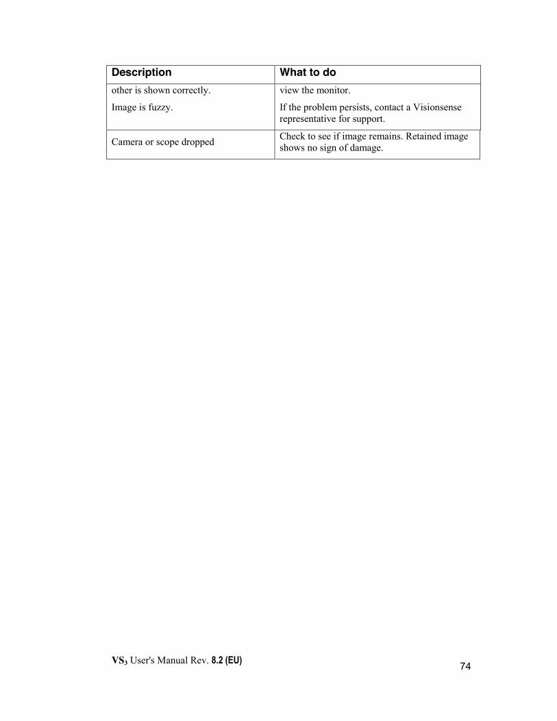
VS3 User's Manual Rev. 8.2 (EU)
74
Description What to do other is shown correctly.
Image is fuzzy.
view the monitor.
If the problem persists, contact a Visionsense representative for support.
Camera or scope dropped Check to see if image remains. Retained image shows no sign of damage.

VS3 User's Manual Rev. 8.2 (EU)
75
Appendix A: VSII Endoscope (optional)
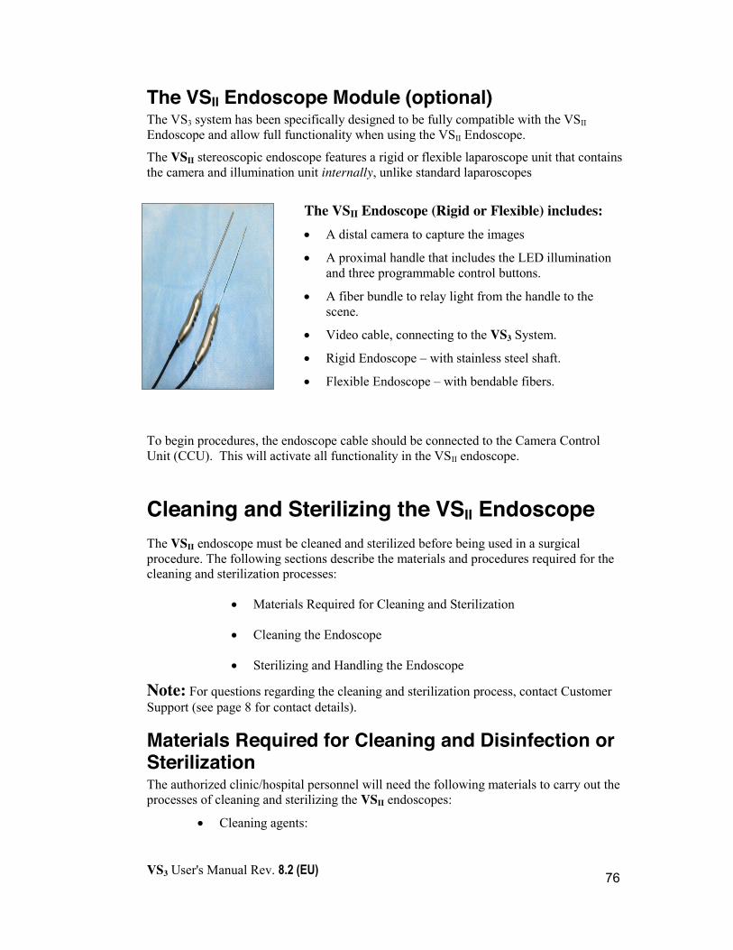
VS3 User's Manual Rev. 8.2 (EU)
76
The VSII Endoscope Module (optional) The VS3 system has been specifically designed to be fully compatible with the VSII Endoscope and allow full functionality when using the VSII Endoscope.
The VSII stereoscopic endoscope features a rigid or flexible laparoscope unit that contains the camera and illumination unit internally, unlike standard laparoscopes
The VSII Endoscope (Rigid or Flexible) includes: x A distal camera to capture the images
x A proximal handle that includes the LED illumination and three programmable control buttons.
x A fiber bundle to relay light from the handle to the scene.
x Video cable, connecting to the VS3 System.
x Rigid Endoscope – with stainless steel shaft.
x Flexible Endoscope – with bendable fibers.
To begin procedures, the endoscope cable should be connected to the Camera Control Unit (CCU). This will activate all functionality in the VSII endoscope.
Cleaning and Sterilizing the VSII Endoscope The VSII endoscope must be cleaned and sterilized before being used in a surgical procedure. The following sections describe the materials and procedures required for the cleaning and sterilization processes:
x Materials Required for Cleaning and Sterilization
x Cleaning the Endoscope
x Sterilizing and Handling the Endoscope
Note: For questions regarding the cleaning and sterilization process, contact Customer Support (see page 8 for contact details).
Materials Required for Cleaning and Disinfection or Sterilization The authorized clinic/hospital personnel will need the following materials to carry out the processes of cleaning and sterilizing the VSII endoscopes:
x Cleaning agents:

VS3 User's Manual Rev. 8.2 (EU)
77
- Enzymatic Detergent5
- Non-Enzymatic Detergent6
- Any cleaning solution that is approved by your institution's protocol for endoscopic equipment - See the following Cautions:
Cautions
¾ Cleaning agents must state Aluminum Suitability by the manufacturers ¾ Cleaning agents should be up to pH=10.0
x Tap water
x Sterile water
x Large water basin (approximately 40cm X 40cm X 20cm)
x Scrub brush (such as the “3M brush team”)
x Sterile gauze pads
x Sterile, no powder gloves
x Protective attire according to institutional protocol
x Endoscope and protective cap
x Sterilization box
Cleaning the VSII Endoscope (Rigid and Flexible) Both new endoscopes and those previously used in a procedure must be cleaned before disinfection or sterilization. When the physician/surgeon has finished using an endoscope, it must be promptly prepared for cleaning by the authorized personnel.
MANDATORY - Prior to any cleaning or immersing, make sure to cover the male part of the medical connector attached to the endoscope's main cable with the protective cap and to properly tighten the cap.
Note: The protective cap is intended to secure the connector throughout the entire cleaning and sterilization reprocessing and therefore must remain closed until usage. 5 ENDOZIME®, RUHOF CORP. Enzymatic Detergent was validated for cleaning efficacy 6 RENU-KLENZ®, STERIS CORP. Non-Enzymatic Detergent was validated for cleaning efficacy
!
VS3 User's Manual Rev. 8.2 (EU)
78
Cautions
x Failure to cover the endoscope’s connector will result in irreparable damage to the endoscope.
x Ultrasonic cleaning methods are prohibited when cleaning or sterilizing the endoscope or Light Guide.
x Do not pull on the cable connected to the rigid end of the endoscope.
Manual cleaning of VSII Rigid and Flexible Endoscope:
1. Verify that the protective cap is attached to the medical connector of the endoscope main cable. Do not try to immerse the unit without attaching the cap.
2. Rinse the endoscope in warm tap water to remove any tissue debris and/or bloody residue.
3. Use approved cleaning solutions to remove resistant debris.
4. Thoroughly rinse off all soap residue.
5. Dry thoroughly. Do not remove the protective cap.
!

VS3 User's Manual Rev. 8.2 (EU)
79
Automated cleaning of VSII Rigid Endoscope and Cannula: 1. Verify that the protective cap is attached to the medical connector of the
endoscope main cable. Do not try to clean the unit without attaching the cap.
2. Rinse the VSII Rigid Endoscope and Cannula in warm tap water to remove any tissue debris and/or bloody residue.
3. Place the endoscope and cannula in the sterilization tray. Make sure that the Endoscope is properly fixated in the sterilization tray. Place the distal part of the Endoscope (shaft) through the silicon fixation opening and the proximal part of the Endoscope between the silicon fixations (see figure below). Make sure the excess cable and connector are placed behind the Endoscope’s handle. For ultimate cleaning, do not place the knobs of the Endoscope’s handle in contact with the silicone fixation
4. Use the automated washer according to hospital protocol for using such a cleaner.
5. Store the dry Endoscope and Cannula. Do not remove the protective cap.
After the cleaning has been completed, the Endoscope and/or Cannula can be stored or disinfected/sterilized for immediate use.
Figure 11: Endoscope and Cannula
VS3 User's Manual Rev. 8.2 (EU)
80
Cleaning the VSII Cannula VSII Cannulas are reusable and must be thoroughly cleaned after each use to remove contaminating substances prior to sterilization.
Manual cleaning of the Cannula: 1. Rinse the Cannula in warm tap water to remove any tissue debris and/or
bloody residue.
2. Remove temporarily the grommet.
3. Clean thoroughly the Cannula and grommet with a mild soapy solution.
4. Use appropriate brushes for cleaning the cannula including the lumen.
5. Run cleaning solution through lumen.
6. Dry thoroughly the entire cannula, including the lumen.
7. Attach back the grommet on proximal side of Cannula.
8. Cleaned Cannula should be wrapped prior to sterilization with cotton cloth.
9. Complete preparation for sterilization in accordance to hospital’s approved protocol.
Note: on first use of new Cannula start cleaning process from step (2).
Automated wash of the Cannula: See “Automated cleaning of the VSII Rigid Endoscope and Cannula” on page 79.
Terminally Sterilizing the VSII Endoscope The VSII endoscopic equipment is supplied non-sterile and must be terminally sterilized by authorized clinic/hospital personnel prior to use. In the current version of the VSII System, authorized personnel can sterilize the VSII endoscope unit using low temperature sterilization processes, such as STERRAD® (STERRAD® 50/100S/200/NX/100NX Systems).
Visionsense Autoclave approved endoscopes are marked on the shafts with “A134°c”. Autoclave approved endoscopes are approved for autoclave processing at 134°c for at least 6 minutes.
Autoclave approved cameras should be autoclaved in accordance with the hospital protocols, yet should meet the processing specifications mentioned above.
Important: Before performing the cleaning or autoclave process it is mandatory to verify that the camera’s connector protective cap is properly tightened in place.
Cautions Note the following precautions prior to sterilizing the VSII endoscope:
!
VS3 User's Manual Rev. 8.2 (EU)
81
x Do not sterilize the endoscope via gamma irradiation
x Do not perform autoclave sterilization for VSII cameras that are not marked by “A134°c” on its shaft as autoclave approved. This can damage the camera irreversibly!
x Do not perform autoclave sterilization for Flexible VSII endoscope. This can damage the Endoscope irreversibly!
x Follow manufacturer instructions for sterilization.
x Do not use cleaning and/or sterilization processes that have not been validated.
x In order to help prevent Health Care Associated Infections (HAI) do not use cleaning or sterilization processes that have not been validated including automated washers, immediate use (flash) sterilization, etc. For more information on HAI please reference “Rutala, W.A., Weber D. J., & HICPAC. (2008). Guideline for Disinfection and Sterilization in Healthcare Facilities, 2008. Atlanta, GA”; available at Centers for Disease Control web site www.cdc.gov .
Warning
x Do not remove the protective cap before cleaning – not even during the transition between cleaning and sterilizing. Removing the protective cap may result in a contaminated device. Only authorized personnel outside the sterile zone should remove the protective cap prior connecting the Camera’s connector to the Camera Control Unit (CCU).
x This device is used in the neurosurgical field where there is a high-infectivity risk of Creutzfeldt-Jakob disease (a.k.a. TSE, CJD) or similar prions in patients who are known or suspected to be infected. Dispose or destroy devices that have been used on patients suspected of having Creutzfeldt-Jakob disease or other prion diseases according to the WHO guidelines, unless sterilizing the devices with STERRAD 100NX Standard Cycle process which is currently thought to eradicate prions. This device is fabricated of materials which can withstand the reprocessing exposure conditions of STERRAD 100NX sterilization. To learn more about this disease you may wish to consult the WHO guidelines - World Health Organization’s 1999 guidance document (Infection Control Guideline for Transmissible Spongiform Encephalopathies. Geneva, Switzerland).
!

VS3 User's Manual Rev. 8.2 (EU)
82
x The qualified ASP STERRAD® Sterilization Systems are: STERRAD® 50, 100S, 200, NX Standard Cycle, and 100NX, Standard and DUO Cycles only (100NX Express Cycle is not qualified). Please refer to ASP/ STERRAD® System User’s Guide for the appropriate cycle in each STERRAD® system for the instrument to be reprocessed. All instruments must be cleaned, rinsed, and thoroughly dried prior to placement in a STERRAD® sterilizer.
Terminally Sterilizing the VSII Cannula The Cannula (with grommet) should be autoclaved at a temperature of 121°C (250°F) to 132°C (270°F) for 20 minutes. Note: In any case of contraindications, the hospital’s policy and/or procedures may take precedence over this protocol.
Caution: Federal Law restricts this device to sale by or on the order of a licensed physician or healthcare provider.


![· SHIM SACD Dire Straits rLove Over Gold] (Private Investigations) ' Clear Cygnus SACD ' , IRIDIUM , IRIDIUM , IRIDIUM 11.5 AWG , , PFA 3455R IRIDIUM Clear Cygnus , 5 Trigon Exxpert](https://static.documents.pub/doc/80x56/60d04de1d6909b691a4f38e7/shim-sacd-dire-straits-rlove-over-gold-private-investigations-clear-cygnus.jpg)


