.. ,.. ,. -..,. ., ;“:.” ,. :. :,: 4 , Instruction QR-25” Series “VT Manual for Compressors CAUTION Vacuum pumps are complicated and can cause serious injury or death if operated improperly. Before installing or operating this vacuum pump, read and understand this manual, and follow all safety precautions!! I 52201-104 February 1994
Transcript
..,..
,.-..,. .,;“:.”
,. :.:,:
4
,
InstructionQR-25” Series
“VT
Manual forCompressors
CAUTIONVacuum pumps are complicated and can causeserious injury or death if operated improperly.
Before installing or operating this vacuum pump, readand understand this manual, and follow all safety precautions!! I
52201-104 February 1994
2 YEAR WAH34+WY W?OGKAMGhdncy Compressor Division
Industrial Reciprocating Products
QR-25, Gf& PLT5eries
2-5tage Compressor
A two year warranty is available for the basic compressor
bypurchasing warranty maintenance kits. The warranty main-
tenance kits contain lubricant, filter(s) and registration infor-
mation for one year. Near the end of the firet year, Quincy
Compressor will remind you, by mail, that a second year of
warranty may be obtained by purchasing a second warranty
maintenance kit. (Kits may be purchased from the same place
you bought your compressor.)
Your basic compressor will have the same coverage for the
secondyearas it had for the first. You simply follo wthe recom-
mended maintenance spelled out intheinstruction manual. The
two year warranty oniyapplies when the maintenance kits are
purchased for the first &secondyearofservice and registered
within thirty days of compressor purchase.
.—.,.—. —-.—...-. -.—..-.
--
QR-25 Series QUINCY COMPRESSOR
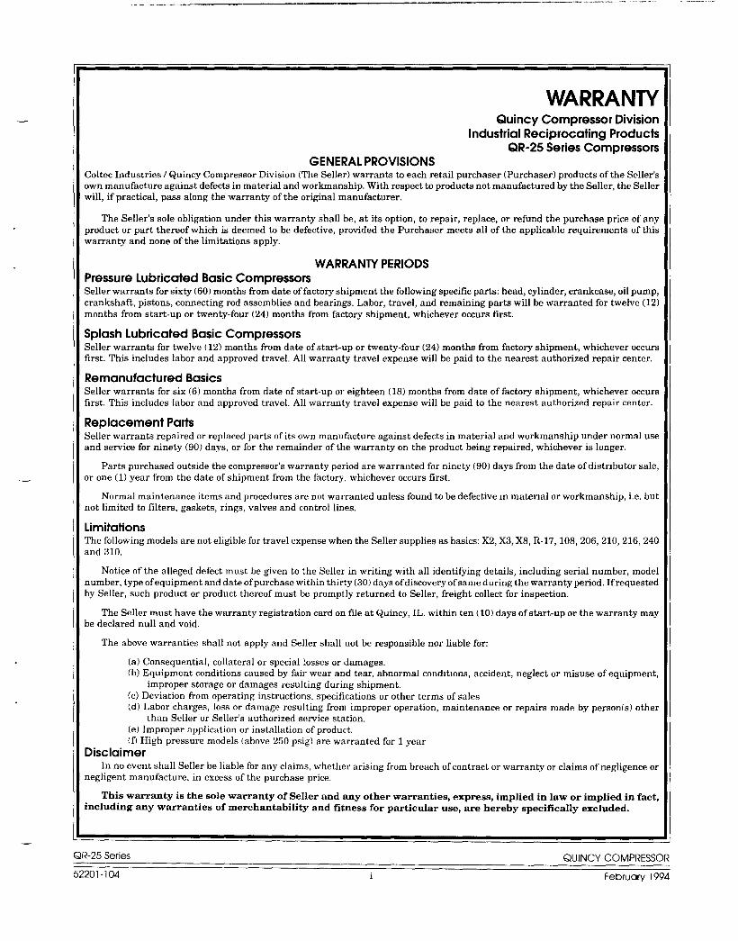
WARRANTYQuincy Compressor Division
Industrial Reciprocating ProductsQR-25 Series Compressors
GENERAL PROVISIONSColtec Industries/ Quincy Compressor Division (The Seller) warrants to each retail purchaser (Purchaser) products of the Seller’sown manufacture against defects in material and workmanship, With respect to products not manufactured by the Seller, the Sellerwill, if practical, pass along the warranty of the original manufacturer.
The Seller’s sole obligation under this warranty shall be, at its option, to repair, replace, or refund the purchase price of anyproduct or part thereof which is deemed to be defective, provided the Purchaser meets all of the applicable requirements of thiswarranty and none of the limitations apply.
WARRANTY PERIODSPressure Lubricated Basic CompressorsSeller warrants for sixty (60) months from date of factory shipment the following specific parts: head, cylinder, crankcase, oil pump,crankshaft, pistons, connecting rod assemblies and bearings. Labor, travel, and remaining parts will be warranted for twelve (12)months from start-up or twenty-four (24) months from factory shipment, whichever occurs first,
Splash Lubricated Basic CompressorsSeller warrants for twelve (12) months from date of start-up or twenty-four (24) months from factory shipment, whichever occursfirst. This includes labor and approved travel, All warranty travel expense will be paid to the nearest authorized repair center.
Remanufactured BasicsSeller warrants for six (6) months from date of start-up or eighteen (18) months from date of factory shipment, whichever occursfirst. This includes labor and approved travel. All warranty travel expense will be paid to the nearest authorized repair center.
Replacement PartsSeller warrants repaired or replaced parts of its own manufacture against defects in material and workmanship under normal useand service for ninety (90) days, or for the remainder of the warranty on the product being repaired, whichever is longer.
Parts purchased outside the compressor’s warranty period are warranted for ninety (90) days from the date of distrlbutar sale,or one (1) year from the date of shipment from the factory, whichever occurs first.
Normal maintenance items and promdures are not warranted unless found to be defective m material or workmanship, i.e. butnot limited to filters, gaskets, rings, valves and control lines.
LimitationsThe following models are not eligible for travel expense when the Seller supplies as basics: X2, X3, X8, R-17, 108,206, 210,216,240and 310.
Notice of the alleged defect must be given to the Seller in writing with all identifying details, including serial number, modelnumber, type of equipment and date of purchase within thirty (30) days of discovery of same during the warranty period. If requestedby Seller, such product or product thereof must be promptly returned to Seller, freight collect for inspection.
The Seller must have the warranty registration card on file at Quincy, IL. within ten ( 10) days of start-up or the warranty maybe declared null and void.
The above warranties shall not apply and Seller shall not be responsible nor liable for:
(a) Consequential, collateral or special losses or damages.(b) Equipment conditions caused by fair wear and tear, abnormal condltlons, accident, neglect or misuse of equipment,
improper storage or damages resulting during shipment,(c) Deviation from operating instructions, specifications or other terms of sales(d) Labor charges, loss or damage resulting from improper operation, maintenance or repairs made by person(s) other
than Seller or Seller’s authorized service station.(e) Improper application or installation of product,If) High pressure models (above 250 psig) are warranted for 1 year
Disclaimerin no event shall Seller be liable for any claims, whether arising from breach of contractor warranty or claims of negligence or
negligent manufacture. in excess of the purchase price,
This warranty is the sole warranty of Seller and any other warranties, express, implied in law or implied in fact,including any warranties of merchantability and fitness for particular use, are hereby specifically excluded.
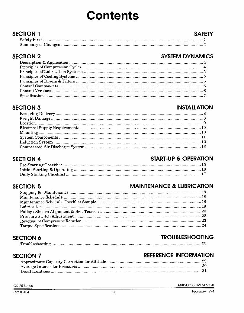
Principles of Lubrication Systems .........................................................................................................5Principles of Cooling Systems ...c............................................................................................................5Principles of Dryers & Filters ................................................................................................................5Control Components ...............................................................................................................................6Control Versions .....................................................................................................................................6Specifications ..........................................................................................................................................7
SECTION 3 INSTALLATIONReceiving Delivery ..................................................................................................................................8Freight Damage ......................................................................................................................................8Location ...................................................................................................................................................9Electrical Supply Requirements ..........................................................................................................lOMounting ...............................................................................................................................................lOSystem Components ....................................................................................................................c........llInduction System ..................................................................................................................................l2Compressed ArDischarge System ......................................................................................................l3
—At Quincy Compressor safety is not only a primary concern, but a faithfullyperformed practice. Beginning with the design stage, safety is built into “TheWorld’s Finest Compressor”. It is the intention of this manual to pass along the“safety first” concept to you by providing safety precautions throughout itspages,
DANGER
WMNING
CAUTION !
.—
“DANGER !“, ‘WARNIN G !“, and “CAUTION !“ are displayed in largebold capital letters in the left hand column to call attention to areas of vitalconcern. They represent different degrees of hazard seriousness, as statedbelow. The safety precaution is spelled out in bold upper and lowercase lettersin the right hand column.
Immediate hazards which will result in severe personal injury ordeath.
Hazards or unsafe practices that could result in personal injury ordeath.
Hazards or unsafe practices which could result in minor personalinjury, product or property damage.
Each section of this instruction manual, as well as any instructions suppliedby manufacturers of supporting equipment, should be read and understoodprior to starting the compressor. If there are any questions regarding any partof the instructions, please call your local Quincy Compressor Distributor, or theQuincy Compressor factory before creating a potentially hazardous situation.Life, limb, or equipment could be saved with a simple phone call.
Compressors are precision high speed mechanical equipment requiringcaution in operation to minimize hazard to property and personnel, There aremany obvious safety rules that must be observed in the operation of this typeof equipment. Listed below are some additional safety precautions that mustbe observed.
●Transfer of toxic, dangerous, flammable or explosive substances using QuincyCompressor products is at the user’s risk.
. Turn off and lockoutitagout (per O. S.H.A regulation 1910.147) the mainpower disconnect switch before attempting to work or perform any mainte-nance.
● Do not attempt to service any part of the unit while it is operating,
● Per O.S.H.A regulation 1910.147, relieve the system of all pressure beforeattempting to service any part of the unit.
● Do not operate the unit with any of its safety guards, shields, or screens
QR-25 Series removed.QUINCY COMPRESSOR
52201-104 1 February 1994
DANGER !
● Do not remove or paint over any DANGER!, WARNING!, CAUTION!, orinstructional materials attached to the compressor, Lack of informationregarding hazardous conditions can cause property damage or personal injury.
● Periodically check all pressure relief valves for proper operation.
. Do not change the pressure setting of the pressure relief valve, restrict thefunction of the pressure relief valve, or replace the pressure relief valve witha plug.
. Do not install a shutoff valve in the compressor discharge line without firstinstalling a pressure relief valve of proper size and design between the shutoffvalve and the compressor.
.Do not use plastic pipe, rubber hose, or lead-tin soldered joints in any part ofthe compressed air system.
● Alterations must not be made to this compressor without Quincy Compressor’sapproval.
● Be sure that all tools, shipping and installation debris have been removedfrom the compressor and installation site prior to starting the compressor.
● Do not operate the compressor in excess of the A. S.M. E. pressure vessel ratingfor the receiver or the service rating of the compressor, whichever is lower.
● Make a general overall inspection of the unit daily and correct any unsafesituations.
●Reckless behaviour of any kind involving compressed air is dangerous andcan cause very serious injury to the participants.
c Provisions should be made to have the instruction manual readily availableto the operator and maintenance personnel. If for any reason any part of themanual becomes illegible or the manual is lost, have it replaced immediately.The instruction manual should be read periodically to refresh one’s memory.It may prevent a seriouk or fatal accident.
● Never use a flammable or toxic solvent for cleaning the air filter or any parts.
Air used for breathing or food processing must meet O.S.HA. 29C.F.R. 1910.134 or F.DA. 21 C.F.R. 178.3570 regulations. Failure todo so may cause severe injury or death.
W~NING !Do not operate a Quincy Compressor in excess of 250 p.s.i.g. unlessit has been tested and certified for high pressure application byQuincy Compressor prior to shipment.
The owner, lessor or operator of any compressor unit manufactured byQuincy Compressor is hereby warned that failure to observe the above safetyprecautions may result in serious injury to personnel and/or damage toproperty.
Quince Compressor neither states as fact, nor in any way implies that theabove list of safety precautions is an all inclusive list, the observance of whichwill prevent all damage to property or injury to personnel.
Every effort has been taken to ensure that complete and correct instructionshave been included in this manual. However, possible product updates andchanges may have occurred since this printing, Quincy Compressor reservesthe right to change specifications without incurring any obligation for equip-ment previously or subsequently sold.
Summary of Changes to This Manual(since previous printing dated August 1992):
. Model 240 was included in the “Limitations” section of the Warranty
. information pertaining to Principles of Dryers & Filters was added toSection 2
0maximum P.S. I .G. for Model 216 was limited to 100 P. S.I. G. in theSpecifications table
“ Torque Specifications table now includes information for obsolete models
The Quincy Compressor QR-25Series consists of heavy dutyindustrial, belt driven, single ortwo stage compressors. Singlestage compressors are capable ofdelivering up to 100 P. S.I.G. con-tinuously. Some single stagecompressors are capable of de-livering up to 150 P. S.I.G.intermittantly (with proper con-trols and modifications). Twostage compressors can deliverup to 200 P. S.I. G. continuously,andupto250, 350 or500P.S.I,G.intermittently depending uponthe model, controls and configu-ration.
Principles of Compres-sion Cycles
Single Stage Compressors
During the downstroke of a singlestage compressor, air is drawnthrough an intake valve in thehead of the compressor and intothe cylinder. At the bottom ofthe stroke, the intake valve closesand air is trapped in the cylin-
der. The air is then compressed in the cylinder during the upstroke of thepiston. Total compression, from atmospheric pressure to the final dischargepressure, is accomplished in one stroke of the piston.
Two Stage Compressors
During the downstroke of the piston of a two stage compressor, air is drawnthrough an intake valve in the head of the compressor into the low pressurecylinder and compressed during the upstroke of the piston.
The compressed air is then released through a discharge valve in the headof the compressor to an intercooler (usually finned tubing) where the heatresulting from compression is allowed to dissipate, The cooler compressed airis then drawn into a second compression cylinder, the high pressure cylinder,for compression to final pressure.
From there the compressed air is released through a discharge valve to anair receiver tank or directly to a network of compressed air supply lines. In onerevolution of the crankshaft a compression cycle is completed.
(..) R-7!i %ria QUINCY COMPRESSOR—,.-- -- .,--
52201-104 4 February 1994
..... . ..-.—.— - ——. ... ... .. . . .. . . .....
Principles of Lubm”cation Systems
Splash Lubricated Models
With each stroke of the compressor, a dipper attached to the bottom of theconnecting rod, dips into an oil bath at the bottom of the crankcase. This dippersplashes oil throughout the interior of the crankcase, lubricating all movingparts.
It is important with this system that the oil level be maintained between thehigh and low level marks on the dipstick. If the oil level is too high, excessiveoil carryover could result. If the oil level is too low, or the compressor is notoperated within the correct R.P. M. range, the moving parts will not beadequately lubricated.
Pressure Lubricated Models
Moving parts within the crankcase are supplied with lubrication by a positivedisplacement, gerotor type oil pump, Oil is drawn up from the bottom of thecrankcase to the oil pump through an oil sump strainer screen. The oil is thenforced under pressure through the oil filter (if so equipped). Oil travels underpressure through drilled journals in the crankshaft and connecting rods tolubricate crankshaft bearings, wrist pin bearings and the cylinder walls.
Pm”nciples of Cooling Systems
Aircooled Models
Fan blades of the compressor sheave force ambient air across fins of thecylinder head(s), and intercooler fins of two stage compressors, to cool thecompressor. QR-25 series compressors are normally setup at the factory witha sheave that turns in a counterclockwise rotation. For special applications,clockwise rotation compressor sheaves are available as optional equipment onsome models. Due to standard drive motor limitations, it is recommended thatthe compressor be operated in temperatures under 104”F,
Watercooled Models
In addition to cooling action provided by the fan blades of the compressorsheave, cool water is circulated throughout an internal water jacket surround-ing the cylinders and heads of watercooled models.
Principles of Dryers & Filters
Moisture occurs naturally in air lines as a result of compression. Moisturevapor in ambient air is concentrated when pressurized and condenses whencooled in downstream air piping, Compressed air dryers reduce the moisturevapor concentration and prevent water formation in compressed air lines.Dryers are a recommended companion to filters, aftercoolers, and automaticdrains for improving the productivity of compressed air systems.
Water and moisture vapor removal increases the efficiency of air operatedequipment, reduces contamination and rusting, increases the service life ofpneumatic equipment and tools, prevents air line freeze-ups, and reducesproduct rejects.
.QR-25 Series QUINCY COMPRESSOR
52201-104 5 February 1994
Control Components
Unloader Towers Provided as part of the basic compressor when controlversion is specified.
Pilot Valve: Used in conjunction with unloader towers when the compressoris to run continuously and an operating pressure range is to be maintained.Refer to your parts manual for correct pilot valve, ranges and settings,
Hydraulic Unloade~Used on pressure lubricated compressors to protect thecompressor in the event of a potentially damaging oil pressure drop. Alsoensures that the compressor does not begin to produce compressed air untilthere is sufficient oil pressure.
Pressure Switch Used for startktop applications (usually accompanied by ahydraulic unloader). The pressure switch detects the demand for compressedair and allows the unit to start. When the demand is satisfied, the unit stops.
Control Versions
Various control versions are available for the model QR-25 series compres-sors. The control version required is determined by how frequent there is
Ea. ““’O’”’”’O””s
‘-------’k
a demand for compressed air. The idea is to create compressed air on,– demand, but to limit the number of times a motor must start the compressor
FROM THE
+ AIR REcEIVEBin a given time period. To prevent motor burnout, the motor should be
,,-—<,,-—,- .-,-\ limited to no more than six (6) starts per hour.,
~++;}~’,L-’I ‘ ‘ “ HYDRAULIC
J\;>, !\; “~~~~~~
Control Version P: Describes a basic compressor with no added control!;I1t! 1.*!,\,\\ ‘Y ~~ features., \ ~, r-”, , ,, .a_ld.‘. /’ I
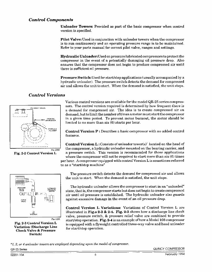
,; “---<’ ~, Control Version L: Consists of unloader tower(s)* located on the head of-APIX 1069 the compressor, a hydraulic unloader mounted on the bearing carrier, and
Fig. 2-2 Control Version L a pressure switch. This version is recommended for those applicationswhere the compressor will not be required to start more than six (6) times
per hour. A compressor equipped with control Version L is sometimes referredto as a “starthtop machine”
—m —.PRR:SLS::E AUTOMATIC
VALVE
$lixi;:
The pressure switch detects the demand for compressed air and allowsthe unit to start. When the demand is satisfied, the unit stops.
The hydraulic unloader allows the compressor to start in an “unloaded”state, that is, the compressor starts but does not begin to create compressedair until oil pressure is established. The hydraulic unloader also guardsagainst excessive damage in the event of an oil pressure drop.
L&J Control Version L Variations: Variations of Control Version L areillustrated in Figs 2-3 & 2-4. Fig. 2-3 shows how a discharge line checkvalve, pressure switch, & pressure relief valve are combined to provide
Plx1155
Fig. 2-3 Control Version Lstartistop operation. Fig. 2-4 is an example of how a Model 108 compressor
Variation (Discharge Lineis equipped with a flyweight controlled three-way valve and head unloader
Check Valve & Pressurefor startJstop operation.
Switch)
*1, 2, or 4 unloader towers are employed depending upon the model of compressor.
QR-25 Series QUINCY COMPRESSOR
52201-104 6 February 1994
———. .—.—..— ..
.—----=3
UNLOADER TOWE~S
,-----1
!
OEARINGADJ;~Ll#EENT
/
TuBE’F ROMAIR RECEIVER
~, 1156
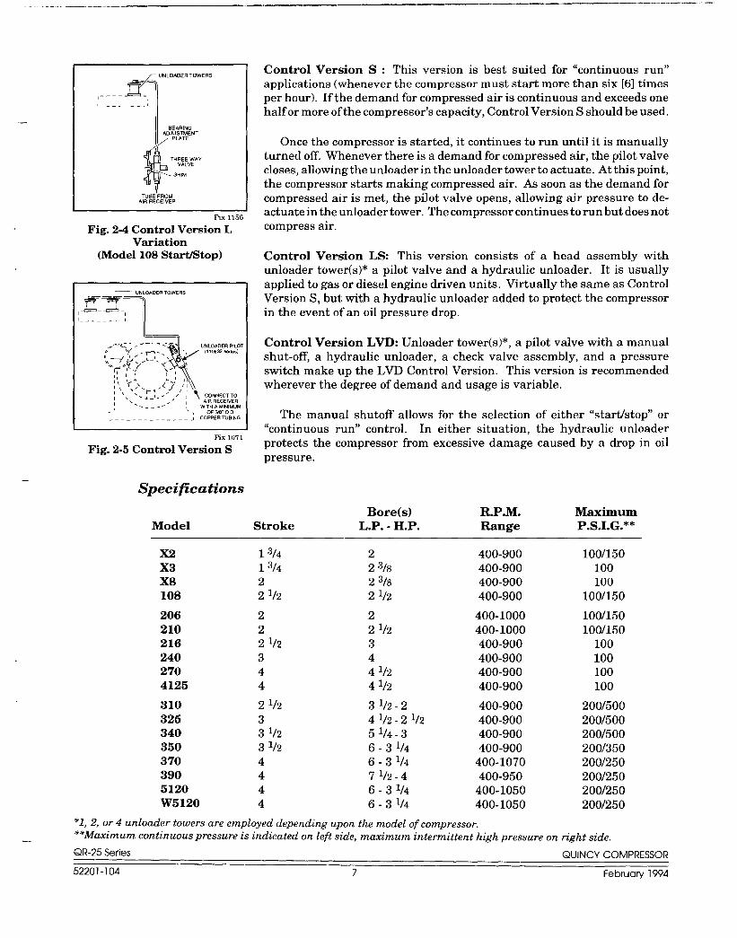
Fig. 2-4 Control Version LVariation
(Model 108 Start/Stop)
‘— UNLOADER TOWERS
JTIT--------1
I
Pix1071
Fig. 2-5 Control Version S
Control Version S : This version is best suited for “continuous run”applications (whenever the compressor must start more than six [6] timesper hour). If the demand for compressed air is continuous and exceeds onehalf or more of the compressor’s capacity, Control Version S should be used.
Once the compressor is started, it continues to run until it is manuallyturnecl off, Whenever there is a demand for compressed air, the pilot valvecloses, allowing the unloader in the unloader tower to actuate. At this point,the compressor starts making compressed air. As soon as the demand forcompressed air is met, the pilot valve opens, allowing air pressure to de-actuate in the unloader tower. The compressor continues to run but does notcompress air.
Control Version LS: This version consists of a head assembly withunloader tower(s)* a pilot valve and a hydraulic unloader. It is usuallyapplied to gas or diesel engine driven units. Virtually the same as ControlVersion S, but with a hydraulic unloader added to protect the compressorin the event of an oil pressure drop.
Control Version LVD: Unloader tower(s)*, a pilot valve with a manualshut-off, a hydraulic unloader, a check valve assembly, and a pressureswitch make up the LVD Control Version. This version is recommendedwherever the degree of demand and usage is variable,
The manual shutoff allows for the selection of either “startistop” or“continuous run” control. In either situation, the hydraulic unloaderprotects the compressor from excessive damage caused by a drop in oilpressure.
Specifications
Bore(s) R.P.M. MaximumModel Stroke L.P. - H.P. Range P.S.I.G.**
*1, 2, or 4 unloader towers are employed depending upon the model of compressor.**Minimum continuous pressure is indicated on left side, maximum intermittent high pressure on right side.
QR-25 Series QUINCY COMPRESSOR
52201-104 7 February 1994
INSTALLATIONSECTION 3
Receiving
CAUTION !
Delivery
Immediately upon receipt of compressor equipment and prior to completelyuncrating, the following steps should be taken:
Step 1) Inspect compressor equipment for damage that may have occurredduring shipment. If any damage is found, demand an inspectionfrom the carrier. Ask the carrier how to file a claim for shippingdamages. (Refer to SECTION 3, Freight Damage for completedetails.) Shipping damage is not covered by Quincy Com-pressor warranty.
Step 2) Insure that adequate lifting equipment is available for moving thecompressor equipment.
Improper lifting can result in component or system damage, orpersonal injury. Follow good shop practices and safety procedureswhen moving the unit.
Step 3) Read the compressor nameplate to verify the model and sizeordered.
Step 4) Read the motor nameplate to be sure the motor is compatible withyour electrical conditions (volts, phase, hertz).
Step 5) Read the pressure relief valve nameplate to be sure it does notexceed the working pressure shown on the compressor or any othercomponent in the system.
Step 6) Read and understand the safety precautions containedwithin this manual. The successful and efficient operation ofcompressor equipment depends largely upon the amount of caretaken to install and maintain the equipment. Quincy Compressorstrongly recommends that any or all person(s) in charge of install-ing, maintaining, or servicing one of our compressors read andunderstand the entire contents of this manual in order to performsuch duties safely and efilciently.
Freight Damage
It is extremely important that you examine every carton and crate as soon asyou receive it, If there is any obvious damage to the shipping container, havethe delivering carrier sign the freight bill, noting the apparent damage, andrequest a damage report.
If concealed damage is discovered at a later date, the carrier mustbe notified within 15 days of initial receipt of freight. Concealedshipping damage is not covered by Quincy Compressor Warranty.Contact the carrier as soon as possible, giving them an opportunity to inspectthe shipment at the premises where the delivery was made. Do not move thedamaged freight from the premises where the original delivery was made.
QR-25 Series QUINCY COMPRESSOR
52201-104 8 February 1994
... ——.—” —. -— ——
Location
CAUTION
W~NING
Retain all containers and packing for inspection by the carrier.
A claim form can be requested from the carrier: Standard Form forPresentation of Loss and Damage Claims (form # 3208). Your claim will needto be substantiated with the following documents:
a.) form #3208
b.) original bill of lading
c.) original paid freight bill
d.) original invoice or certified copy
e.) other particulars obtainable in proof of loss or damage (photos,damage inspection, etc.)
The proper description and classification of our product in the NationalMotor Freight Classification 1OO-H,contained in item 118100, reads as follows:Compressors, air, or air ends: with or without air tanks, hose or nozzles,mounted or not mounted. ”
We suggest that these instructions be circulated to your shipping andreceiving personnel,
Quincyaircompressors should beinstalledinan area that is clean, well lighted,and adequately ventilated. Inspection and maintenance checks are requireddaily. Therefore, sufficient space needs to be provided around the compressorfor safe and proper inspection, cleaning, and maintenance.
The compressor must not be installed closer than 24 inches to a wall oranother compressor. This allows ample circulation of air across the compressorcylinders, heads and cooler (if so equipped). If at all possible, the pulley drivesystem (i.e. motor pulley, compressor sheave, belts and guard) should belocated next to a wall to minimize any danger created by the drive system whilethe compressor is operating.
Due to standard drive motor limitations, it is recommended that thecompressor be operated in temperatures under 104”F. In cold climates, thecompressor should be installed in a heated building.
!Do not operate this compressor in ambient temperatures lowerthan -15” F. A crankcase heater is recommended for a compressorthat is to operate in temperatures under 32° F.
!Under no circumstances should a compressor be used in an areathat may be exposed to toxic, volatile, or corrosive atmosphere. Donot store toxic, volatile, or corrosive agents near the compressor.
Noise
Noise is a potential health hazard that must be considered. There are federaland local laws governing acceptable noise levels. Check with local officials forspecifications.
QR-25 Series QUINCV COMPRESSOR
52201-104 9 February 1994
CAUTION !
Electrical
DANGER !
W~NING
CAUTION
Excessive noise can be effectively reduced through various methods. Totalenclosures, intake silencers, baffle walls, relocating or isolating the compressorcan reduce noise levels. Care must be taken when constructing total enclosuresor baffle walls. If not properly constructed or positioned, they could contributeto unacceptable noise levels or overheating. Consult your local QuincyCompressor Distributor if assistance is required.
Unusual noise or vibration indicates a problem. Do not operate thecompressor until the source has been identified and corrected.
%pply Requirements
The electrical installation of this unit should be performed by a qualifiedelectrician with knowledge of the National Electrical Code (N, E.C.), O. S.H.A.code andlor any local or state codes having precedence.
Before installation, the electrical supply should be checked for adequatewire size and transformer capacity. A suitable circuit breaker or fuseddisconnect switch should be provided. When a 3 phase motor is used to drivea compressor, any unreasonable voltage imbalance between the legs must beeliminated and any low voltage corrected to prevent excessive current draw.Note: This unit must be grounded.
The installation, electric motor, wiring, and all electrical controls must bein accordance with NFPA 70-1993 National Electric Code, National ElectricSafety Code, state and local codes. Failure to abide by the national, state andlocal codes may result in physical harm and/or property damage.
High voltage may cause personal injury or death. Disconnect andIockoutitagout per O. S.HA. regulation 1910.147 all electrical powersupplies before opening the electrical enclosure or servicing.
Never assume a compressor is safe to work on just because it is notoperating. It could restart at any time. Follow all safety precau-tions outlined in SECTION 5, Stopping For Maintenance.
NEMA electrical enclosures and components must be appropriateto the area installed.
Mounting
Proper mounting of Quincy compressors is crucial to the safe operation andlongevity of the equipment. The installation requires a flat and level concretefloor or pad. Satisfactory results can usually be obtained by mounting thecompressor on vibration isolating pads available from your local QuincyDistributor.
State or local codes may mandate that the compressor be bolted to the floor.In this case the unit must be leveled and bolted making absolutely certain thefeet are not stressed in any manner. Uneven feet drawn tightly to the concretepad will cause severe vibrations resulting in cracked welds or fatigue failure.
QR-25 Series QUINCY COMPRESSOR
52201-104 10 February 1994
—- ——”—
—.-.
.
The customer is responsible for providing a suitable foundation & isolatormounting where necessary.
Mounting Mobile Units
Gas engine driven compressors mounted to truck beds should be fastened insuch a way so as not to create any stress to the air receiver tank. Truck beds,characteristically, have a tendency to flex and could cause damage to thereceiver tank if the tank is fastened directly to the truck bed. It is the User’sresponsibility to provide an adequate means of fastening the unit in theseapplications.
System components
Efficiency and safety are the primary concerns when selecting components forcompressed air systems. Products of inferior quality can not only hinderperformance of the unit, but could cause system failures that result in bodilyharm or even death. Select only top quality components for your system. Callyour local Quincy Distributor for quality parts and professional advice.
Drive Pulleys / Sheaves
Various pulley and sheave combinations are available to obtain the desired airpressure and delivery rate of your compressor. Consideration must be givento these combinations to ensure that the motor is not overloaded by operatingabove or below the designed speed range.
-.
Whatever combination is employed, the drive pulleys&compressor sheavesmust be properly aligned and drive belt tension set to specifications (refer toSECTION 5, Pulley lS?zeaveAlignment &Belt Tension). Improper pulley/sheave alignment and belt tension can cause motor overloading, excessivevibration, and premature belt andlor bearing failure.
Excessive compressor RPM’s (speed) could cause a pulley or sheaveto shatter. In an instant, the pulley or sheave could separate into
WARNING ! fragments capable of penetrating the belt guard and causing bodilyharm or death. Do not operate the compressor above the recom-mended RPM (refer to SECTION 2, Specifications).
Guards
All mechanical action or motion is hazardous in varying degrees and needs tobe guarded, Guards should be designed to achieve the required degree ofprotection and still allow full air flow from the compressor sheave across theunit. Guards shall be in compliance with OSHA safety and health standards29 CFR 1910.219 in OSHA manual 2206 and any state or local codes.
Guards must be fastened in place before starting the compressor
W~NING ! andneverremoved before cutting offandlockingout the mainpower supply.
Check Valves
Check valves are designed to prevent back-flow of air pressure in the com-pressed air system (air flows freely in one direction only). The check valve must
QR-25 Series QUINCY COMPRESSOR
52201-104 11 February 1994
be properly sized for air flow and temperature. Do not rely upon a checkvalve to isolate a compressor from a pressurized tank or compressedair delivery system during maintenance procedures!
Manual Shutoff Valves
Manual shutoff valves block the flow of air pressure in either direction. Thistype of valve can be used to isolate a compressor from a pressurized system,provided the system is equipped with a pressure relief valve capable of beingmanually released. The pressure relief valve should be installed between themanual shutoff valve and the compressor (refer toFig. 3-1, Typical Drop Leg& Component Location).
Pressure Relief Valves
Pressure relief valves aid in preventing system failures by relieving systempressure when compressed air reaches a determined level. They are availablein various pressure settings to accommodate a range of applications. Pressurerelief valves are preset by the manufacturer and under no circumstancesshould the setting be changed by anyone other than the manufacturer.
Pressure relief valves are designed to protect compressed air
DANGER ! systems in accordance with ASME B19 safety standards. Failure toprovide properly sized pressure relief valves may cause propertydamage, severe personal injury or even death.
Induction System
Air Intake
A clean, cool and dry air supply is essential to the satisfactory operation of yourQuincy air compressor. The standard air filter that the compressors equippedwith when leaving the factory is of sufficient size and design to meet normalconditions, when properly serviced, in accordance with the maintenancesection of this manual.
If, however, the compressor is to be installed in a location where consider-able dust, dirt and other contaminants are prevalent, consult your local QuincyDistributor for advice and optional filters. It is the user’s responsibility toprovide adequate filtration for those conditions. Oil bath filters are not to beused. Warranty will be void if a failure is determined to be caused byinadequate filtration.
Remote Inlet Filters
Depending on the size of the compressor and the size and construction of theroom in which the unit operates, the air inlet may have to be located outsideof the room. If it is necessary to remotely install the air filter, make the inletpiping as short and direct as possible. Remotely installed air filters can leadto vibrations in the inlet piping. These vibrations can be minimized by addinga pulsation dampener in the inlet piping between the remote inlet filter(s) andthe compressor.
If the intake is piped to outside atmosphere, a hooded filter should beinstalled to prevent water or snow from being ingested into the compressor.
All inlet piping should beat least the same size (or larger) in diameter as theinlet connection to the compressor. For every 10 feet of inlet piping or every 90°bend, increase the inlet piping diameter by one pipe size. The inlet piping mustbe thoroughly clean inside. Remove all weld slag, rust or dirt. Galvanized pipewith threaded or flanged fittings is preferred.
Never locate the compressor air inlet system where toxic, volatile
CAUTION ! or corrosive vapors, air temperatures exceeding 100”F, water, orextremely dirty air could be ingested. These types of atmospherescould adversely affect the performance of the compressor system.
Compressed Air Discharge System
The discharge piping should be of the same diameter as the compressordischarge connection, or sized so that the pressure drop at any point in thesystem does not exceed 10% of the air receiver pressure. Install auxiliary airreceivers near heavy loads or at the far end of a long system. This will insuresuilicient pressure if the use is intermittent, or sudden large demands areplaced on the system.
I IFig. 3.1 Typical Drop Leg & Component Location PM1007
Discharge piping should slope to a drop leg (refer to Fig. 3-1, Typical DropLeg & Component Location) or moisture trap to provide a collection pointwhere moisture can be easily removed. All service line outlets should beinstalled above the moisture traps to prevent moisture from entering the toolor device using the air. Manual shutoff valves, protected by pressure reliefvalves, should be installed at all service line outlets to eliminate leakage whilethe tools are not in use.
As with any piping, all parts of the discharge piping should fit so as not tocreate any stress between the piping and components.
.+ QR-25 Series QUINCY COMPRESSOR
52201-104 13 February 1994
Pnuematic Circuit Breakers or Velocity Fuses
The Occupational Safety and Health Act (0. S. H.A.), Section 1926.303, Para-graph 7, published in the Code of Federal Regulations 29 CFR 1920.1, revisedJuly 1, 1982 states that all hoses exceeding l/2° inside diameter shall have asafety device at the source of supply or branch line to reduce pressure in caseof a hose failure”
These pnuematic safety devices are designed to prevent hoses from whip-ping and/or the loss of hazardous or toxic gasses, all of which could result in aserious or fatal accident.
Never join pipes or fittings with lead-tin soldering. Welded orW~NING ! threaded steel pipes and cast iron fittings, designed forthepres-
sures and temperatures, are recommended.
Pressure Vessels
Air receiver tanks and other pressure containing vessels such as (but notlimited to) pulsation bottles, heat exchangers, moisture separators and traps,shall be in accordance with ASME Boiler and Pressure Vessel Code SectionVIII and ANSI B 19.3 safety standards. They should be equipped with apressure reliefvalve, pressure gauge, tank drain, & manual shutoffvalve (referto Fig. 3-1, Typical Drop Leg& Component Location).
ASME coded pressure vessels must not be modified, welded, re-
WMNING ! paired, reworked or subjected to operating conditions outside thenameplate ratings. Such actions will negate code status, affectinsurance status and may cause property damage, severe injury oreven death.
A drain valve should be located in the bottom of the air receiver to allow formoisture drainage. Extend piping away from the unit to provide safe andconvenient removal of excess moisture. An automatic drain valve is recom-mended.
If the air receiver is going to be subject to temperatures of 32°F or below,provisions must be made to guard against freezing of the pressure reliefvalves,pressure gauge, and moisture drain.
QR-25 Series QUINCY COMPRESSOR
52201-104 14 February 1994
.--—.—,— .“.—. . ------ . . . ..—. --—
—
SECTION 4 START-UP & OPERATION
Pre-starting Checklist
W~NING
WMNING
!Never assume a compressor is safe to work on just because it is notoperating. It could restart at any time. Follow all safety precau-tions outlined in SECTION 5, Stopping For Maintenance.
! Failure to perform the pre-starting checklist may result in me-chanical failure, property damage , serious injury or even death.
Steps 1 through 12 should be performed prior to connecting the unitto a power source. If any condition of the checklist is not satisfied, make thenecessary adjustments or corrections before starting the compressor.
Step 1)
Step 2)
Step 3)
Step 4)
Step 5)
Step 6)
Step 7)
Step 8)
Step 9)
Step 10)
Step 11)
Remove all installation tools from the compressor and check forinstallation debris.
Unless otherwise specified, Quincy compressors are nor-mally shipped without lubricant in the crankcase. Addcorrect amount of specified oil to the crankcase. (Refer to SEC-TION 5, Lubrication for quantity and types of lubricant to beused. )
Check motor pulley and compressor sheaves for alignment andtightness on shaft. (Refer to SECTION 5, Pulley / SheaveAlignment & Belt Tension. )
Manually rotate the compressor sheave several rotations to be surethere are no mechanical interferences.
Check inlet piping installation (Refer to SECTION 3, InductionSystem. )
Check belt tension. (Refer toAlignment & Belt Tension. )
Check all pressure connections
SECTION 5, Pulley / Sheave
for tightness.
Make sure all pressure relief valves are correctly installed. (Referto SECTION 3, System Components. )
Be sure all guards are in place and securely mounted. (Refer toSECTION 3, System Components. )
Check fuses, circuit breakers, and thermal overloads for propersize. (Refer to SECTION 3, Electrical Supply Requirements. )
Open all manual shutoff valves at and beyond the compressordischarge,
QR-25 Series QUINCY COMPRESSOR
52201-104 15 February 1994
Step 12) On watercooled units, open the water valve to fill the coolingsystem, Check for leaks.
If a manual water valve is used, adjust the valve to maintain an adequateflow of water.
If a water temperature regulator valve is used, install a small bypass orificein front of the regulator valve to allow heated water to circulate around thetemperature sensing bulb at all times.
Step 13) After all the above conditions have been satisfied, the unit can beconnected to the proper power source.
Step 14) Jog the starter switch to check the rotational direction of thecompressor. It should agree with the rotation arrow embossed onthe compressor sheave,
. .Step 15) Check for proper rotation of the cylinder cooling fan (fins inside
sheave). The fan should blow cooling air across the cylinder.
Initial Starting & Operating
This instruction manual, as well as any instructions supplied by manufactur-ers of supporting equipment, should be read and understood prior to startingthe compressor. If there are any questions regarding any part of the instruc-tions, please call your local Quincy Distributor, or the Quincy Compressorfactory.
With the pre-starting checklist completed and satisfied, start the compres-sor. Watch and listen for excessive vibration and strange noises. If either exist,stop the compressor. Refer to SECTION 6, Troubleshooting for help in
i%X 1068Fig. 4-1
Oil Pressure Adjustment
determining the cause of such problems.
If you are starting a pressure lubricated model, check the oil pressure.Compressors producing up to 250 p.s.i.g. of discharge air pressure shouldmaintain 18 to 20 p.s.i.g. of oil pressure. High pressure rated compressorsproducing more than 250 p.s.i.g. of discharge air pressure should maintain22 to 25 p.s.i.g. of oil pressure.
Normally the oil pressure does not need to be adjusted. But if it does,loosen the locknut on the adjustment screw located on the left side of the oilpump housing (see Fig. 4-1, Oil Pressure Adjustment). Increase the oilpressure by turning the adjustment screw clockwise; decrease the oilpressure by turning the adjusting screw counterclockwise. After adjust-ment tighten the locknut.
Check the air receiver pressure gauge or system pressure gauges forproper readings. If inadequate or excessive air pressure conditions exist, referto Section 6 Troubleshooting.
Observe compressor operation closely for the first hour of operation andthen frequently for the next seven hours. After the first eight hours, monitorthe compressor at least once every eight hours. If any abnormal conditions arewitnessed, stop the compressor and correct the problem. After two days of
operation check belt tension, oil level, and inspect the system for leaks.
Daily Starting Checklist
Do not proceed until the Pre-starting Checklist and Initial Starting &Operating sub-sections have been read and are thoroughly understood.
Step 1)
Step 2)
Step 3)
Step 4)
Step 5)
Step 6)
Step 7)
Step 8)
Step 9)
Check oil level in crankcase.
Drain liquid from the air receiver and moisture trap (if so equipped).
Turn on cooling water (watercooled units)
Jog the starter button and check compressor rotation. Note:Continuous Run Units - Prior to starting a continuous run unit,pull the ring attached to the pilot valve out and turn the finger nutin (clockwise) until it seats against the pilot housing. Now thecompressor can be started unloaded. Once the compressor isrunning at full speed, the finger nut on the pilot valve can be turnedout (counterclockwise) until it seats against the pull ring.
Start compressor per factory instructions. (Refer to SECTION 4,Pre-Starting Checklist and Initial Starting& Operating. )
Check system pressure.
Check cooling fan.
Check all pressure relief valves for proper operation,
Check control system for proper operation.
QR-25 Series QUINCY COMPRESSOR
52201-104 17 February 1994
SECTION 5 MAINTENANCE & LUBRICATION
Stopping for Maintenance
WARNING
The following procedures should be followed when stopping the compressor formaintenance or service:
Step 1) Per O.S.H.A. regulation 1910.147: The Control of HazardousEnergy Source (Lockout/Tagout), disconnect and lockout the mainpower source. Display a sign in clear view at the main power switchstating that the compressor is being serviced.
! Never assume a compressor is safe to work on just because it is notoperating. It could restart at any time.
Step 2)
Step 3)
Step 4)
Step 5)
Step 6)
Isolate the compressor from the compressed air supply by closinga manual shutoff valve upstream and downstream from the com-pressor. Display a sign in clear view at the shutoff valve statingthat the compressor is being serviced.
Lock open a pressure relief valve within the pressurized system toallow the system to be completely de-pressurized. NEVER removea plug to relieve the pressure!
Shut off the water cooling supply (watercooled versions).
Open all manual drain valves within the area to be serviced.
Wait for the unit to cool before starting to service. (Temperaturesof 125°F can burn skin. Some surface temperatures exceed 350°Fwhen the compressor is operating.)
Maintenance Schedule
To assure maximum performance and service life of your compressor, a routinemaintenance schedule should be developed. A sample schedule has beenincluded here to help you to develop a maintenance schedule designed for yourparticular application. Time frames may need to be shortened in harsherenvironments.
The envelope shipped with the compressor contains a MaintenanceSchedule Checklist. Make copies of this checklist and retain the master tomake more copies as needed. On a copy of the checklist, enter dates and initialsin the appropriate spaces. Keep the checklist and this Instruction Manualreadily available near the compressor.
Maintenance Schedule Checklist Sample
Every 8 Hours (or Daily)● Maint ain oil level between high and low level marks on bayonet gauge.(Discoloration or a higher oil level reading may indicate the presenceof condensed liquids. ) If oil is contaminated, drain and replace.
● Drain receiver tank, drop legs and traps in air distribution system.
QR-25 Series QUINCY COMPRESSOR
52201-104 18 February 1994
.-. .—..,. .—. .— .—. -— .x,--— —-—
—
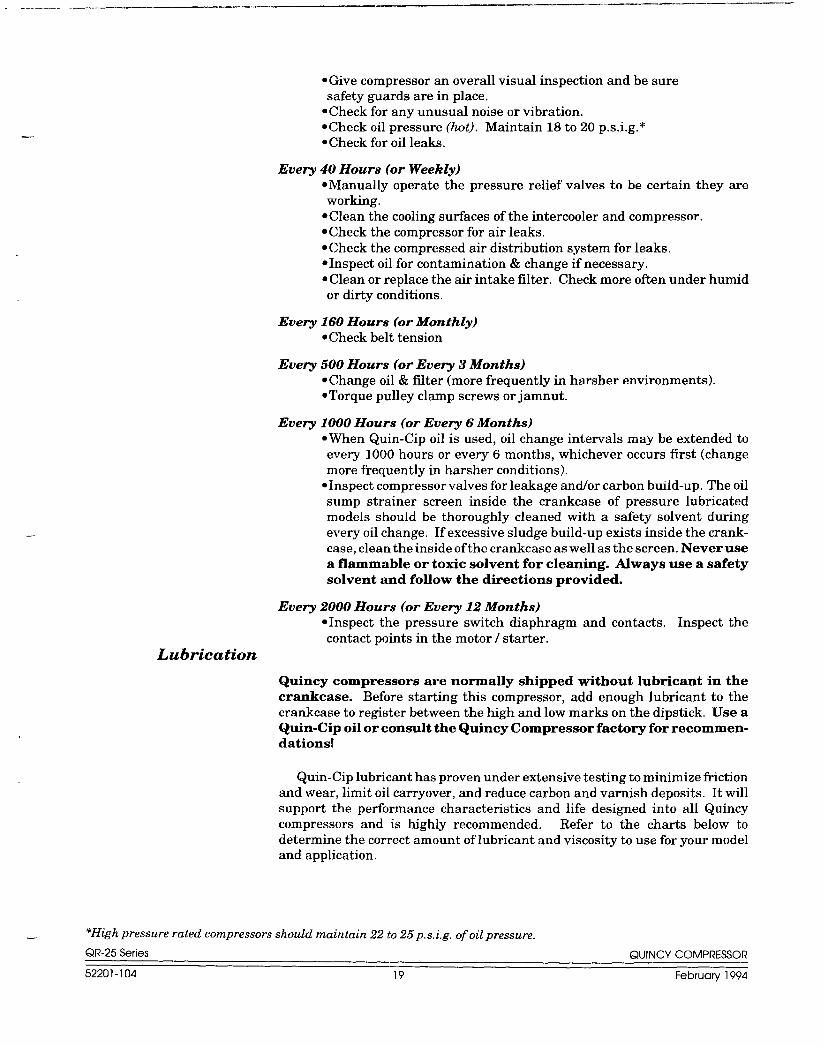
● Give compressor an overall visual inspection and be suresafety guards are in place.
● Check for any unusual noise or vibration..Check oil pressure (hot). Maintain 18 to 20 p.s.i.g. *. Check for oil leaks.
Every 40 Hours (or Weekly). Manually operate the pressure relief valves to be certain they areworking.
c Clean the cooling surfaces of the intercooler and compressor.● Check the compressor for air leaks.● Check the compressed air distribution system for leaks.● Inspect oil for contamination & change if necessary.● Clean or replace the air intake filter. Check more often under humidor dirty conditions.
Every 160 Hours (or Monthly)● Check belt tension
Eve~ 500 Hours (or Every 3 Months). Change oil & filter (more frequently in harsher environments).. Torque pulley clamp screws or jamnut.
Every 1000 Hours (or Every 6 Months)●When Quin-Cip oil is used, oil change intervals may be extended toevery 1000 hours or every 6 months, whichever occurs first (changemore frequently in harsher conditions).
●Inspect compressor valves for leakage and/or carbon build-up. The oilsump strainer screen inside the crankcase of pressure lubricatedmodels should be thoroughly cleaned with a safety solvent duringevery oil change, If excessive sludge build-up exists inside the crank-case, clean the inside of the crankcase as well as the screen. Never usea flammable or toxic solvent for cleaning. Always use a safetysolvent and follow the directions provided.
Every 2000 Hours (or Every 12 Months)● Inspect the pressure switch diaphragm and contacts. Inspect thecontact points in the motor/ starter.
Lubrication
Quincy compressors are normally shipped without lubricant in thecrankcase. Before starting this compressor, add enough lubricant to thecrankcase to register between the high and low marks on the dipstick. Use aQuin-Cip oil or consult the Quincy Compressor factory for recommen-dations!
Quin-Cip lubricant has proven under extensive testing to minimize ftictionand wear, limit oil carryover, and reduce carbon and varnish deposits. It willsupport the performance characteristics and life designed into all Quincycompressors and is highly recommended. Refer to the charts below todetermine the correct amount of lubricant and viscosity to use for your modeland application.
‘High pressure rated compressors should main tain 22 to 25 p.s. i.g. of oil pressure.
QR-25 Series QUINCY COMPRESSOR
52201-104 19 February 1994
Approximate Crankcase Oil Capacities
Splash Lubricated Model Oil Capacity
CAUTION !
CAUTION !
x2&x3 4 oz. (118 ml.)X8 10 oz. (296 ml.)
108 & R-17* 24 oz. (710 ml.)21OSLS 20 oz. (591 ml.)
Pressure Lubricated Model** Oil Capacity
206 &210 20 oz. (591 ml.)216, 240*, 310 & 325 lqt. -16 oz. (1.42 lit.)270*, 340,350 & 370 4 qts, -24 oz. (4.5 lit.)
390 9 qts. -16 oz. (9 lit.)4125”,5120 & W5120 9 qts, -24 oz. (9.22 lit.)
*Includes vacuum pump versions.
**These ~dels may be equipped with oil filters. Add 10 OZ.of011if SOequipped.
Lubricant Specifications
(Use Quin-Cip oil or consult factory.)
Ambient Temperature SAE Viscosity ISO Viscosity
Below O“F SAE 5W ISO 220-32° F SAE low ISO 3232-80”F EL-m20W ISO 68
60-104°F ME 30 ISO 100
The lubricant selected must have a pour point at least 15° Flower than the minimum expected ambient temperature .
Do not operate this compressor in ambient temperatures lowerthan -15° F. A crankcase heater is recommended for compressorsoperating in temperatures under 32° F.
A new or rebuilt reciprocating compressor should be run for a total of 100hours at full discharge operating pressure to break-in the new piston rings.Until the rings are seated, the compressor will discharge higher than normalamounts of oil. In light of this fact, the oil level should be checked morefrequently during the 100 hour break-in period.
Pulley i Sheave Alignment & Belt Tension
Improper pulley/sheave alignment and belt tension are causes for motoroverloading, excessive vibration, and premature belt andfor bearing failure. Toprevent this from happening, check the pulley/sheave alignment and belttension on a regular basis (refer to SECTION 5, Maintenance Schedule).
Periodically inspect the motor pulley(s) and compressor sheave(s) for oil,grease, nicks or burrs. Clean or replace if necessary. Make sure they are
QR-25 Series QUINCY COMPRESSOR
52201-104 20 February 1994
—. -,”, ---,. “.—-,-—.—
-.
.
securely fastened, Align the compressor sheave with the motor or enginepulley. Drive belt grooves of the pulley(s) and sheave(s) should be in line witheach other. The compressor crankshaft must be parallel to the motor or enginedrive shaft.
Belt tension should be measured and adjusted to provide smooth operation.Step-by-step procedures are provided here to correctly measure and set thedrive belt tension:
I
COMPRESSORSHEAVE
DEFLECTION
——— —
DIAMETER~ SPAN LENGTH —-+
Fig. 5-1 Plx 1152
Setting Belt Tension
Step 1) Measure the span length of the drive. (Refer to Fig. 5-1, SettingBelt Tension.)
Belt Motor Pulley RecommendedCross Dia. Range Deflection Force (lbs.)
Section (inches) Minimum Maximum
3.0- 3.2 2.3 3.2A 3.4- 3.6 2.5 3.6
3.8- 4.2 2.9 4.24.6- 7.0 3.5 5.1
4.6 4.0 5.9B 5.0- 5.4 4.5 6,7
5.6- 6,4 5.0 7.46.8- 9.4 5.8 8.6
Step 2) Determine the amount of deflection ( in inches) required to mea-sure deflection force (in pounds) by multiplying the span length xl/w (.016) (i.e. 32” span length x VW[.016] = 1/z’’[.50] of deflectionrequired to measure deflection force).
Step 3) Lay a straightedge across the top outer surface of a drive belt frompulley to sheave.
Step 4) At the center of the span, perpendicular to the belt, apply pressureto the outer surface of the belt with a belt tension gauge (refer toFig. 5-2, Belt Tension Gauge). Force the belt to the predeter-
QR-25 Series QUINCY COMPRESSOR
52201-104 21 Februaty 1994
— . . .. -----
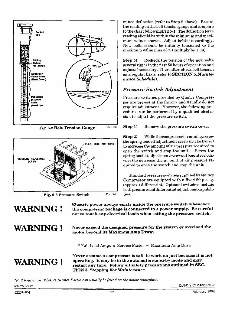
Fig. 5-2 Belt Tension Gauge Pix 1153
CONTACTS
Fig. 5-3 Pressure Switch PIX 1067
mined deflection (refer to Step 2 above). Recordthe reading on the belt tension gauge and compareto the chart followingFig 5-1, The deflection forcereading should be within the minimum and maxi-mum values shown. Adjust belt(s) accordingly.New belts should be initially tensioned to themaximum value plus 33% (multiply by 1.33).
Step 5) Recheck the tension of the new beltsseveral times in the first 50 hours of operation andadjust if necessary. Thereafter, check belt tensionon a regular basis (refer to SECTION 5, Mainte-nance Schedule).
Pressure Switch Adjustment
Pressure switches provided by Quincy Compres-sor are pre-set at the factory and usually do notrequire adjustment. However, the following pro-cedures can be performed by a qualified electri-cian to adjust the pressure switch.
Step 1) Remove the pressure switch cover.
Step 2) While the compressor is running, screwthe spring loaded adjustment screwlh (clockwise)to increase the amount of air pressure required toopen the switch and stop the unit. Screw thespring loaded adjustment screwor4 (counterclock-wise) to decrease the amount of air pressure re-quired to open the switch and stop the unit.
Standard pressure switches supplied by QuincyCompressor are equipped with a fixed 20 p,s.i.g.(approx.) differential. Optional switches includeboth pressure and differential adjustment capabili-ties.
Electric power always exists inside the pressure switch whenever
W~NING ! theC.mpres-packweisc.nnectedt..wwerwwl~.Bec.re~lnot to touch any electrical leads when setting the pressure switch.
W~NING ! Never exceed the designed pressure for the system or overload themotor beyond its Maximum Amp Draw.
* Full Load Amps x Service Factor = Maximum Amp Draw
Never assume a compressor is safe to work on just because it is not
W~NING ! operating. It may be in the automatic stand-by mode and mayrestart any time. Follow all safety precautions outlined in SEC-TION 5, Stopping For Maintenance.
*Full load amps (FLA) & Service Factor can usually be found on the motor nameplate.
QR-25Series QUINCY COMPRESSOR
52201-104 22 February 1994
-.. -.— ,——. ~ .——— .... .
—.
—
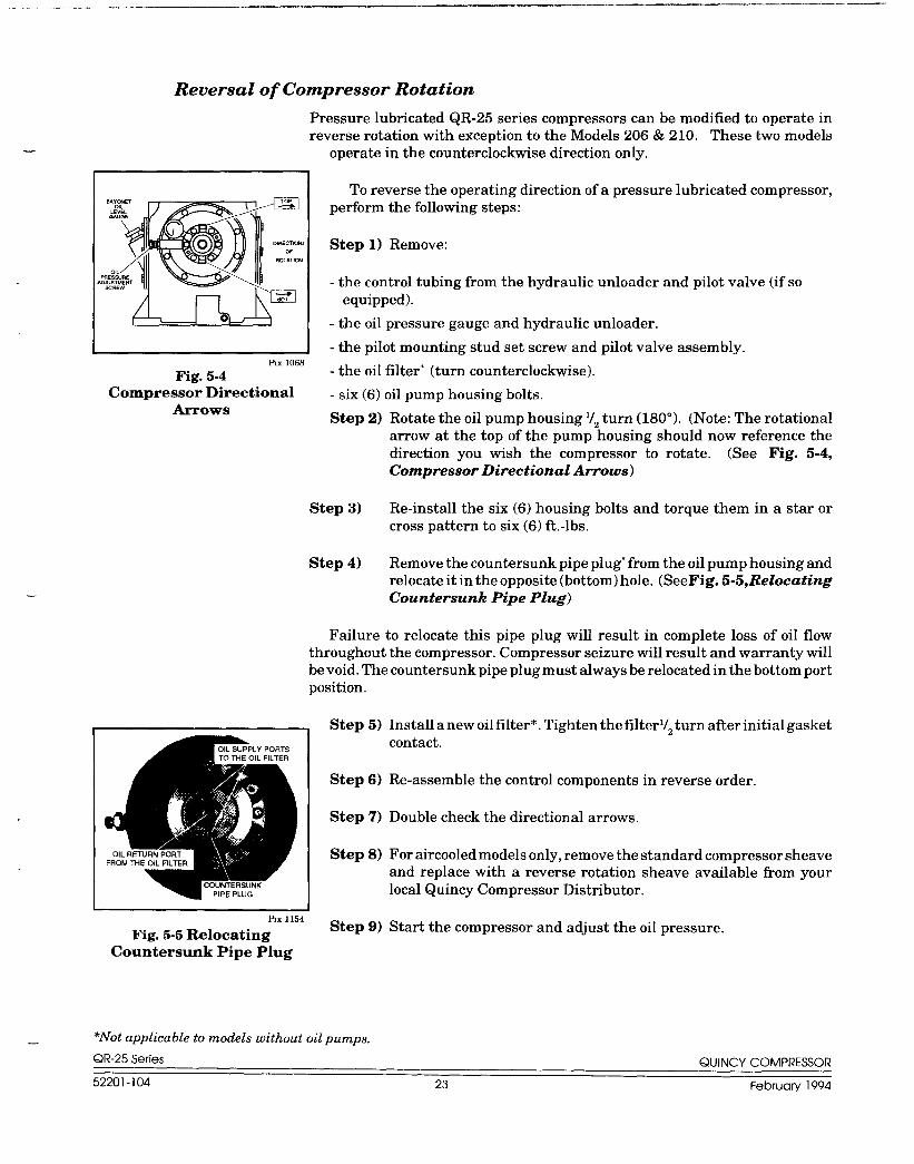
Reversal of Compressor Rotation
Pressure lubricated QR-25 series compressors can be modified to operate inreverse rotation with exception to the Models 206 & 210. These two models
PLx 1068
Fig. 5-4Compressor Directional
&rows
operate in the counterclockwise direction only.
To reverse the operating direction of a pressure lubricated compressor,perform the following steps:
Step 1) Remove:
- the control tubing from the hydraulic unloader and pilot valve (if soequipped).
- the oil pressure gauge and hydraulic unloader.
- the pilot mounting stud set screw and pilot valve assembly.
- the oil filter” (turn counterclockwise).
- six (6) oil pump housing bolts.
Step 2) Rotate the oil pump housing l/. turn (1800). (Note: The rotationalarrow at the top of the pump “housing should now reference thedirection you wish the compressor to rotate. (See Fig. 5-4,Compressor Directional Arrows)
Step 3) Re-install the six (6) housing bolts and torque them in a star orcross pattern to six (6) ft.-lbs.
Step 4) Remove the countersunk pipe plug* from the oil pump housing andrelocate it in the opposite (bottom) hole. (SeeFig. 5-5, RelocatingCountersunk Pipe Plug)
Failure to relocate this pipe plug will result in complete loss of oil flowthroughout the compressor. Compressor seizure will result and warranty willbe void. The countersunk pipe plug must always be relocated in the bottom portposition.
d Step 5) Install a new oil filter*. Tighten the filterl/O turn after initial gasket.contact,
Step 6) Re-assemble the control components in reverse order,
Step 7)
Step 8)
IRx 1154
Fig. 5-5 RelocatingCountersunk Pipe Plug
Step 9)
*Not applicable to models without oil pumps.
Double check the directional arrows.
For aircooled models only, remove the standard compressor sheaveand replace with a reverse rotation sheave available from yourlocal Quincy Compressor Distributor.
Start the compressor and adjust the oil pressure.
QR-25 Series QUINCY COMPRESSOR
52201-104 23 Februarv 1994
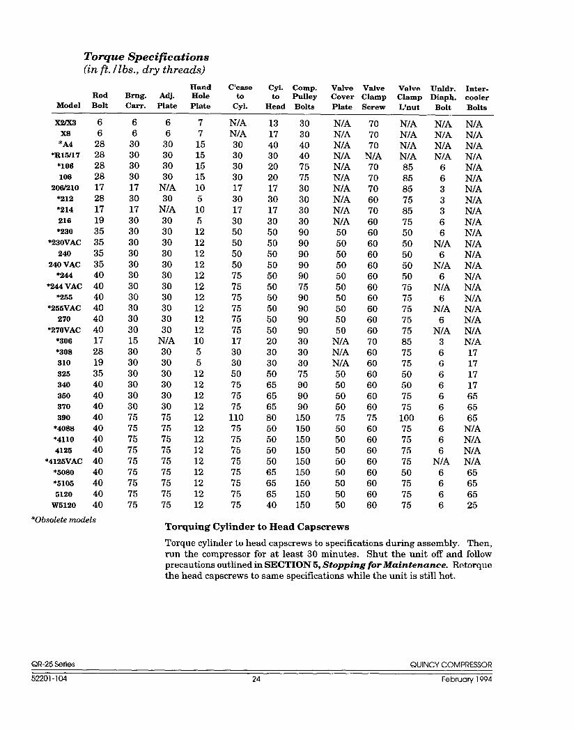
Torque Specifications(in ft. Ilbs., dry threads)
Hand C’caae Cyl. C!omp. Valve ValveRod Brng. Am. Hole
Valve Urddr. Inter-to to Pulley Cover Clamp Clamp Diaph. cooler
Model Bolt Carr. Plate Plate Cyl. Head Bolts Plate Screw L’nut Bolt Bolts
Torque cylinder to head capscrews to specifications during assembly. Then,
run the compressor for at- least 30 minutes. Shut the unit off and followprecautions outlined in SECTION 5, Stopping for Maintenance. Retorque
the head capscrews to same specifications while the unit is still hot.
QR-25Series QUINCY COMPRESSOR
52201-104 24 February 1994
-_. ..___ .___— .,. a.. ———
—. .
.—
—-
..-
SECTION 6 TROUBLESHOOTING
Trouble Probable Cause
Low discharge pressure ● Restricted inlet. Defective compressor valves or valve unloading mechanism. Leaks in the compressed air distribution system at fittings, connections,
etc.. Unloader pilot defective or set wrong● Pressure switch defective or set wrong● Drive belt slipping● 3-way valve defective (Model 108). Flyweight assembly on crankshaft not functioning properly. Incorrect speed●Worn piston rings or loose piston● Faulty hydraulic unloader● Leaking head gasket● Low oil pressurec Drain valve open● Defective pressure gauge. Excessive running clearances (refer to SECTION 2, Specifications)●Pressure relief valve leaking. Clogged intercooler. Loose compressor valves or leaking at valve gasketsc Compressor incorrectly sized for the altitude it is operating at● Piston rings not seated; allow 100 hours at full pressure
Water in the crankcase ●Compressor does not run long enough to get hot and vaporize the liquids(lubricant appears milky) squeezed out of the air during compression
● Leaking water jacket or cylinder headc Incorrect or inferior grade of lubricant● Cooling water circulating in compressor too cold● System pressure leaking back through discharge valve
Rusty valvesand/or cylinders
● Compressor operated too infrequently● Compressor does not run long enough to get hot and vaporize the liquids
squeezed out of the air during compression (compressor may be too largefor application)
● Leaking water jacket or cylinder head● Cooling water circulating in compressor too cold● Compressor not properly prepared for storage● Discharge line from compressor head is pointed upward allowing condensation to drain back at shutdown
Excessive vibration ● Incorrect speed● Compressor valves not functioning properly. Loose pulley/sheave● Motor or engine out of balance● Compressor, motor or engine not secured tightly, or tightened into abind
● Foundation or frame inadequate
QR-25 Series QUINCY COMPRESSOR
52201-104 25 February 1994
Trouble Probable Cause
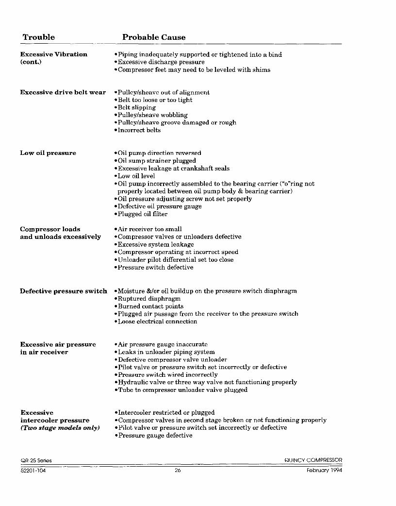
Excessive Vibration ● Piping inadequately supported or tightened into a bind(cont.) ● Excessive discharge pressure
s Compressor feet may need to be leveled with shims
Excessive drive belt wear ● Pulley/sheave out of alignmentQBelt too loose or too tight● Belt slippingQPulley/sheave wobbling● Pulley/sheave groove damaged or rough● Incorrect belts
Low oil pressure . Oil pump direction reversedQOil sump strainer plugged. Excessive leakage at crankshaft seals● Low oil level● Oil pump incorrectly assembled to the bearing carrier (“o’’ring notproperly located between oil pump body & bearing carrier)
s Oil pressure adjusting screw not set properly● Defective oil pressure gauge. Plugged oil filter
Compressor loads ● Air receiver too smalland unloads excessively ● Compressor valves or unloaders defective
● Excessive system leakage● Compressor operating at incorrect speedsUnloader pilot differential set too close● Pressure switch defective
Defective pressure switch ● Moisture &/or oil buildup on the pressure switch diaphragm. Ruptured diaphragm● Burned contact pointsQPlugged air passage from the receiver to the pressure switch. Loose electrical connection
Excessive air pressure ●iAir pressure gauge inaccuratein air receiver ● Leaks in unloader piping system
c Defective compressor valve unloader● Pilot valve or pressure switch set incorrectly or defective. Pressure switch wired incorrectly● Hydraulic valve or three way valve not functioning properly. Tube to compressor unloader valve plugged
Excessive ● Intercooler restricted or pluggedintercooler pressure ● Compressor valves in second stage broken or not functioning properly(TWO stage models only) ● Pilot valve or pressure switch set incorrectly or defective
. Pressure gauge defective
QR-25 Series QUINCY COMPRESSOR
52201-104 26 February 1994
—. ....”--—..—,—. —. —.—. —.—— .—”. ——. —.
Trouble Probable Cause
—
Intercooler pressure ● Compressor valves or valve unloaders in fh-st stage not functioningabnormally low properly or defective(Two stage models only) ● Restricted air inlet falter or suction line
● Pilot valve or pressure switch set incorrectly or defective● Pressurized air at valve unloader not venting properly when demand for
air is required; vent passage at hydraulic unloader or three-way valvecould be plugged
● Compressor valve or head gasket leaking● Worn piston rings● Defective pressure gauge● Leaking air at intercooler or intercooler connections
Compressor overheats ● Clogged intake system● Defective compressor valves● Pressure setting too high● Clogged intercooler, internally or externally● Clogged water passages in cylinder head &/or cylinders● Defective water temperature regulator valve● Inadequate cooling water flow, ventilation, or recirculation of hot air● Pulley/sheave rotation wrong● Incorrect speed● Running clearances insufficient (piston to cylinder wall or running gear)● Lubrication inadequate● Compressor incorrectly sized
High dischargetemperature
● Defective water temperature regulating valve● Inadequate cooling water flow● Compressor valve assemblies defective● Discharge pressure too high● Inadequate ventilation or hot air recirculating● Cooling surfaces of compressor or intercooler excessively dirty● Internal surface of heat exchanger fouled●Ambient temperature too high● Scored or excessively worn cylinder walls● Cooling water temperature too hot
Compressor knocks ● Head clearance insufficient● Piston loose in cylinder bore, cylinder bore worn, piston or piston ringsworn
Excessive oil consumption sCompressor runs unloaded too long● Worn piston rings● Restricted intake system● Compressor running too hot. Breather valve not functioning properlys Oil level in crankcase too highs Oil viscosity wrong for the applicationQConnecting rod out of alignment, bent or twisted● Leaking oil seal● Piston rings not seated (allow 100 hours for seating)● Wrong oil (may be a detergent oil with a tendency to foam)s Inferior grade of oil
Excessive current draw ● Low voltage (must be within 10?ZOof nameplate voltage)
(To determine maximum ● Loose electrical connectionamperage allowed, multiply QWire size too smallthe FLA on the motor QIncorrect oilnameplate by the service ● Discharge pressure too highfactor.) ● Intercooler pluggingCAUTION ! ● Bearings tight or seizingMotor surface temperature ●No crankshaft endplaynormally exceeds 170° F. ● Motor sized incorrectly
● Motor defective● Drive belts too tight
Failure to start ● Power not on. Blown circuit fuse● Thermal overload fuses tripped. Low voltage. Faulty start switch. Power failure● Pressure switch incorrectly adjusted or faulty● Loose or broken wire● Motor defective● Compressor seized
Motor stalls ● Motor overloaded (refer to Excessive current draw)
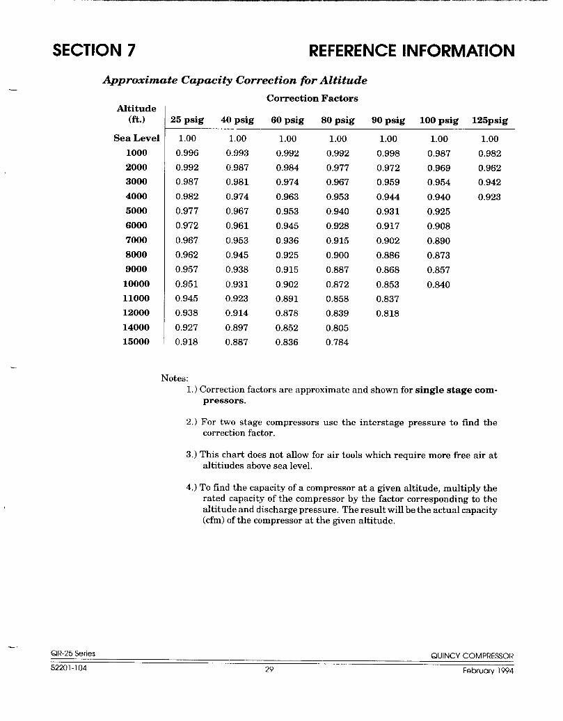
Notes:1.) Correction factors are approximate and shown for single stage com-
pressors.
2.) For two stage compressors use the interstage pressure to find thecorrection factor.
3.) This chart does not allow for air tools which require more free air ataltitudes above sea level,
4.) To find the capacity of a compressor at a given altitude, multiply therated capacity of the compressor by the factor corresponding to thealtitude and discharge pressure. The result will be the actual capacity(cfm) of the compressor at the given altitude.
,—QR-25 Series QUINCV COMPRESSOR
52201-104 29 February 1994
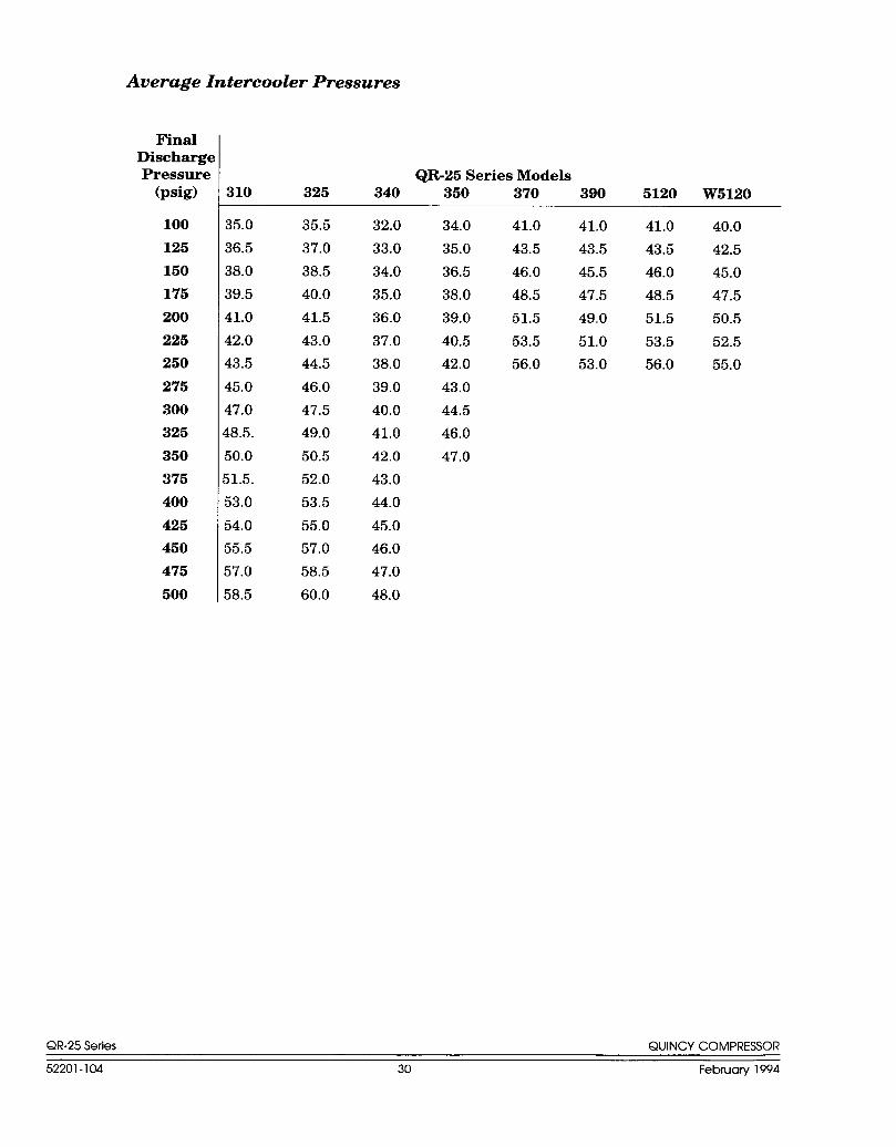
Average Intercooler Pressures
FinalDischargePressure
(psig)
100
125
150
175
200
225
250
275
300
325
350
375
400
425
450
475
500
310
35.0
36.5
38.0
39.5
41.0
42.0
43,5
45.0
47.0
!8.5.
50.0
51.5.
53.0
54.0
55.5
57.0
58.5
QR-25 Series Models325 340 350 370 390 5120 W5120
35.5
37.0
38.5
40.0
41.5
43.0
44.5
46.0
47.5
49.0
50.5
52.0
53.5
55.0
57.0
58.5
60.0
32.0 34.0 41.0 41.0 41.0
33.0 35.0 43,5 43.5 43.5
34.0 36.5 46.0 45.5 46.0
35.0 38.0 48.5 47.5 48.5
36.0 39.0 51.5 49.0 51.5
37.0 40.5 53.5 51.0 53.5
38.0 42.0 56.0 53.0 56.0
39.0 43.0
40.0 44.5
41.0 46.0
42.0 47.0
43.0
44.0
45.0
46.0
47.0
48.0
40.0
42.5
45.0
47.5
50.5
52.5
55.0
QR-25 Series QUINCY COMPRESSOR
52201-104 30 February 1994
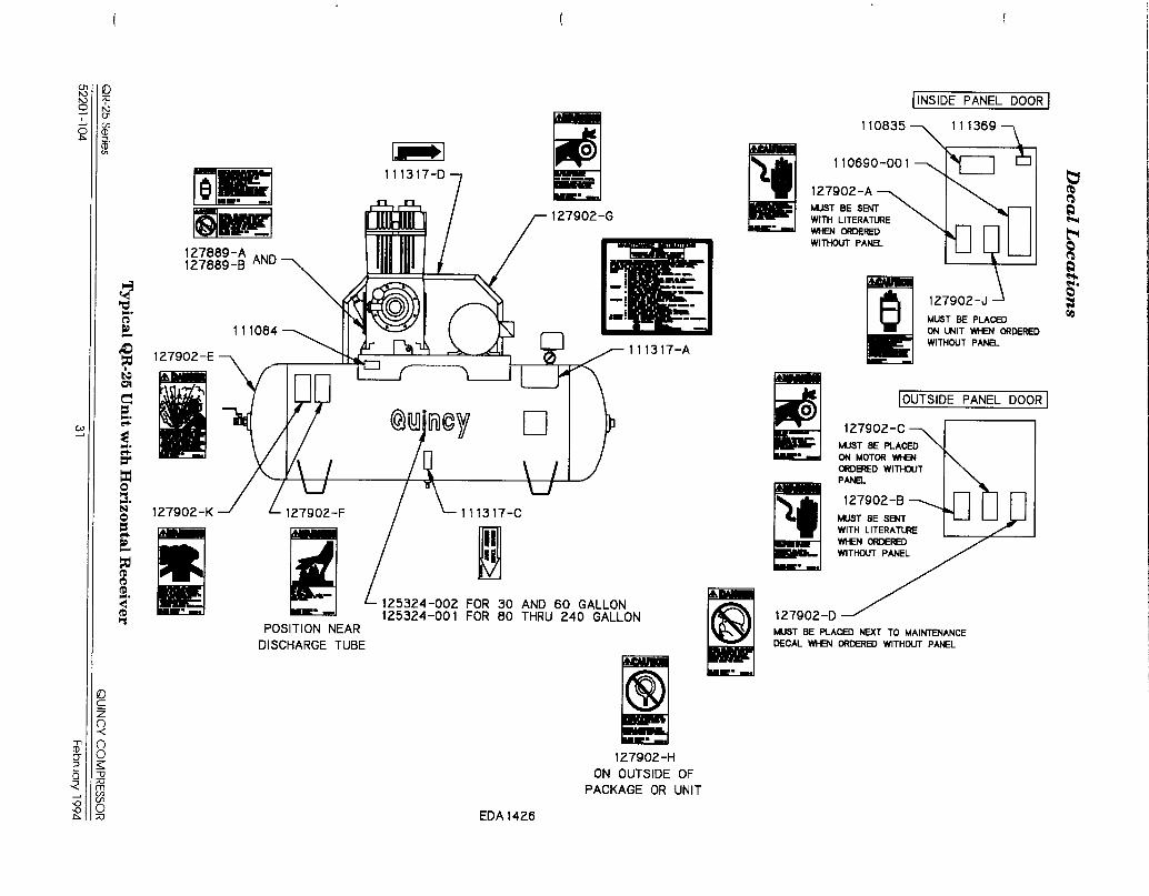
Deca
lL
ocation
s—
-..
m -P’
$J
mm
mm
m9
niilm
li.
QR-25
Series
Typ
icalQ
R-25
Un
itw
ithH
orizontal
Receiver
QU
INC
YC
OM
PRESSOR
52201-10431
Feb
ruary
1994
ml
moP
A
l-l
Typ
icalQ
R-25
Un
itw
ithV
erticalR
eceiver
QR-25
Serie
sQ
UIN
CY
CO
MPRESSO
R
52201-10432
Feb
ruary
1994
LuLmz
-—
Ic1z<~~
Cnm
Coco
Coco
rl-AIA
l--
I(-G
wF
’)
02In
0A
l
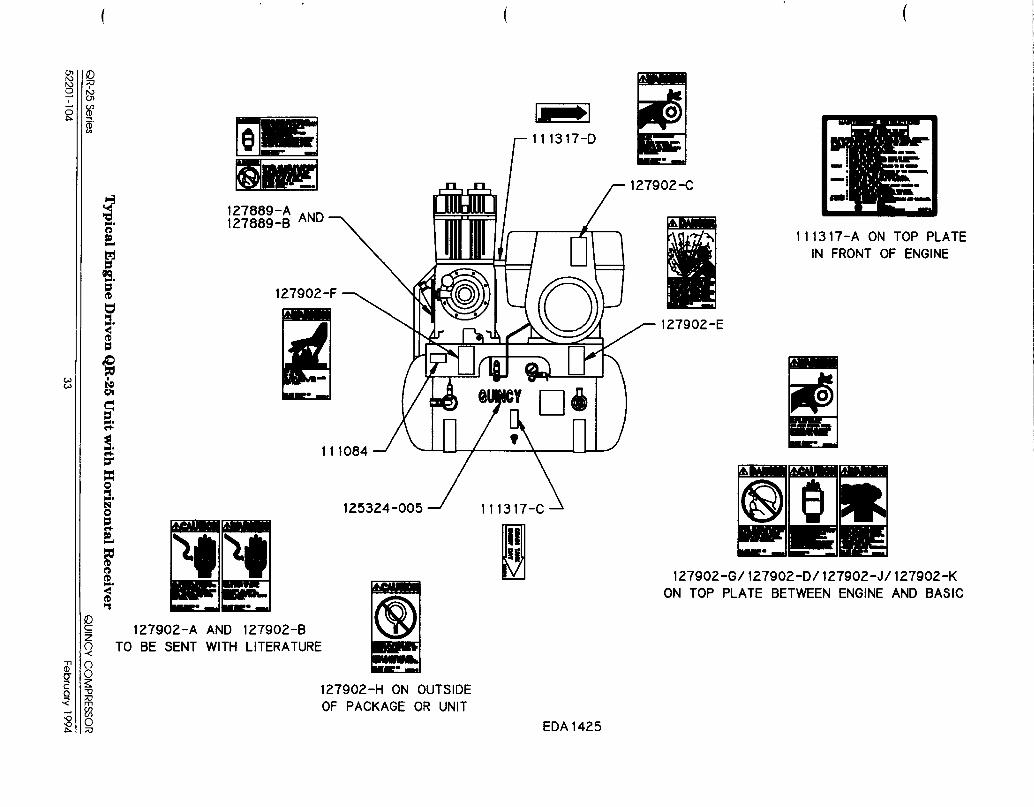
Typ
icalE
ngin
eD
rivenQ
,R-25
Un
itw
ithH
orizontal
Receiver
U3
Nd-
U&
cp~N
<oalm
wr-l-N
Ji
OF
z—
a3
a+
LIEO
v)0)f-w~m“o
1-
QR-25
Serie
sQ
UIN
CY
CO
MPRESSO
R
52201-10433
Feb
ruary
1994
.,
.... .,’
~.. . . . .7.:”.
Quincy Service is always near. For reciprocating products,There are Authorized Quincy Distributors located orbital vane vacuum pump products, and
throughout the United States & Canada that stock natural gas engine driven helical screw products:genuine Quincy parts& accessories for a wide range of call~ -217-222-7700
Quincy products. cr fax requeststo 1-800-219-9124
Quincy Service specialists are factory trained and will For all other helical screw products:help keep you in business. Call for Authorized Quincy calll -334-937-5900
Service. or fax requeststo 1-800-219-9131 Acce@ No Subst,t”tes


![AIR Compressor VT-4-TM MNL[1]](https://static.documents.pub/doc/80x56/563dba09550346aa9aa2230f/air-compressor-vt-4-tm-mnl1.jpg)


