13
VTB 200 Butterfly valves

VTB 200Butterfly valves

Vapo Techniek BV - VTB 200 Butterfly valves / 2doc: jan-2011
Adress
http://www.vapo.nl
Vapo Techniek BVEsp 2585633 AC EindhovenNetherlands
T: +31(0)40 248 10 00F: +31(0)40 248 10 40E: [email protected]
TRADEMARKSFollowing brand names are Dupont registered trademarks:
- Kalrez®
- Viton®
- Teflon®
- Hypalon®
- BUNA-N®
DISCLAIMERVapo Techniek BV has done its utmost to ensure that all data in this documentation is correct. However, Vapo Techniek BV accepts no responsibility for possible problems caused by mistakes in this documentation.
Table of ContentsVTB200 3General information 3Operational data 3Options 3Seat materials and their applications. 3Kv-Values 3
VTB200 DN32/40-300 4Materials 4Dimensions [mm] 4
VTB200 DN32/40-300 5Dimensions [mm] 5
VTB200 DN350-DN600 6Materials 6DN350-DN500 6
VTB200 DN350-DN600 7Dimensions [mm] 7DN600 Monoflange 7
VTB200 DN350-DN600 8Dimensions [mm] 8
VTB200 DN700-DN1200 9Materials 9
VTB200 DN700-DN1200 10Dimensions [mm] 10
Assembly and disassembly instructions 11Montage 11Disassembly 11Removing the valve from the pipeline 11Installing the valves in existing pipelines 12Installing the valve in a new pipeline 12
Additional installation information 13
Vapo Techniek BV - VTB 200 Butterfly valves / 3doc: jan-2011
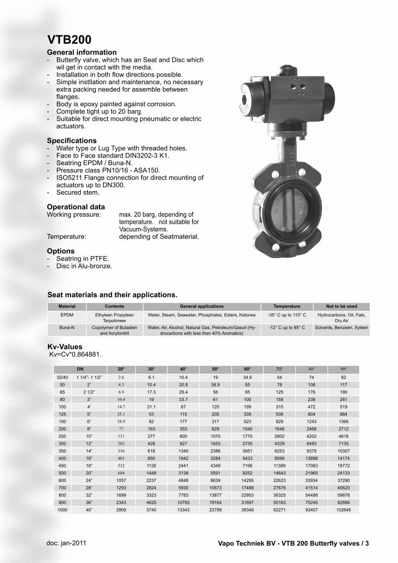
VTB200General information- Butterflyvalve,whichhasanSeatandDiscwhich
wil get in contact with the media.- Installationinbothflowdirectionspossible.- Simpleinstllationandmaintenance,nonecessary
extra packing needed for assemble between flanges.
- Body is epoxy painted against corrosion.- Complete tight up to 20 barg.- Suitablefordirectmountingpneumaticorelectric
actuators.
Specifications- Wafer type or Lug Type with threaded holes.- Face to Face standard DIN3202-3 K1.- SeatringEPDM/Buna-N.- PressureclassPN10/16-ASA150.- ISO5211Flangeconnectionfordirectmountingof
actuators up to DN300.- Securedstem. Operational data Working pressure: max. 20 barg, depending of
temperature. not suitable for Vacuum-Systems.
Temperature: dependingofSeatmaterial. Options - SeatringinPTFE.- Disc in Alu-bronze.
Material Contents General applications Temperature Not to be used
EPDM EthyleenPropyleenTerpolimeer
Water,Steam,Seawater,Phosphates,Esters,Ketones -35° C up to 110° C Hydrocarbons,Oil,Fats,Dry Air
Buna-N Copolymer of Butadien and Acrylonitril
Water,Air,Alcohol,NaturalGas,Petroleum/Gasoil(Hy-drocarbons with less then 40% Aromatics)
-12° C up to 85° C Solvents,Benzeen,Xyleen
Kv-Values Kv=Cv*0.864881.
DN 20° 30° 40° 50° 60° 70° 80° 90°
32/40 1 1/4”- 1 1/2” 2.6 6.1 10.4 19 34.6 54 74 8250 2” 4.3 10.4 20.8 38.9 55 78 108 11765 2 1/2” 6.9 17.3 29.4 56 85 125 176 19080 3” 10.4 19 33.7 61 100 158 238 261100 4’ 14.7 31.1 67 120 199 315 472 519125 5” 25.1 53 115 205 339 536 804 884150 6” 38.9 82 177 317 523 829 1243 1366200 8” 77 163 353 629 1040 1646 2468 2712250 10” 131 277 600 1070 1770 2802 4202 4618300 12” 202 428 927 1653 2735 4329 6493 7135350 14” 336 618 1340 2388 3951 6253 9379 10307400 16” 401 850 1842 3284 5433 8599 13898 14174450 18” 532 1126 2441 4349 7196 11389 17083 18772500 20” 684 1448 3138 5591 9252 14643 21965 24133600 24” 1057 2237 4848 8639 14295 22623 33934 37290700 28” 1293 2824 5930 10573 17488 27676 41514 45620800 32” 1699 3323 7783 13877 22953 36325 54488 59876900 36” 2343 4625 10793 19164 31697 50163 75245 826861000 40” 2909 5740 13343 23789 39348 62271 93407 102645
Seat materials and their applications.
Vapo Techniek BV - VTB 200 Butterfly valves / 4doc: jan-2011
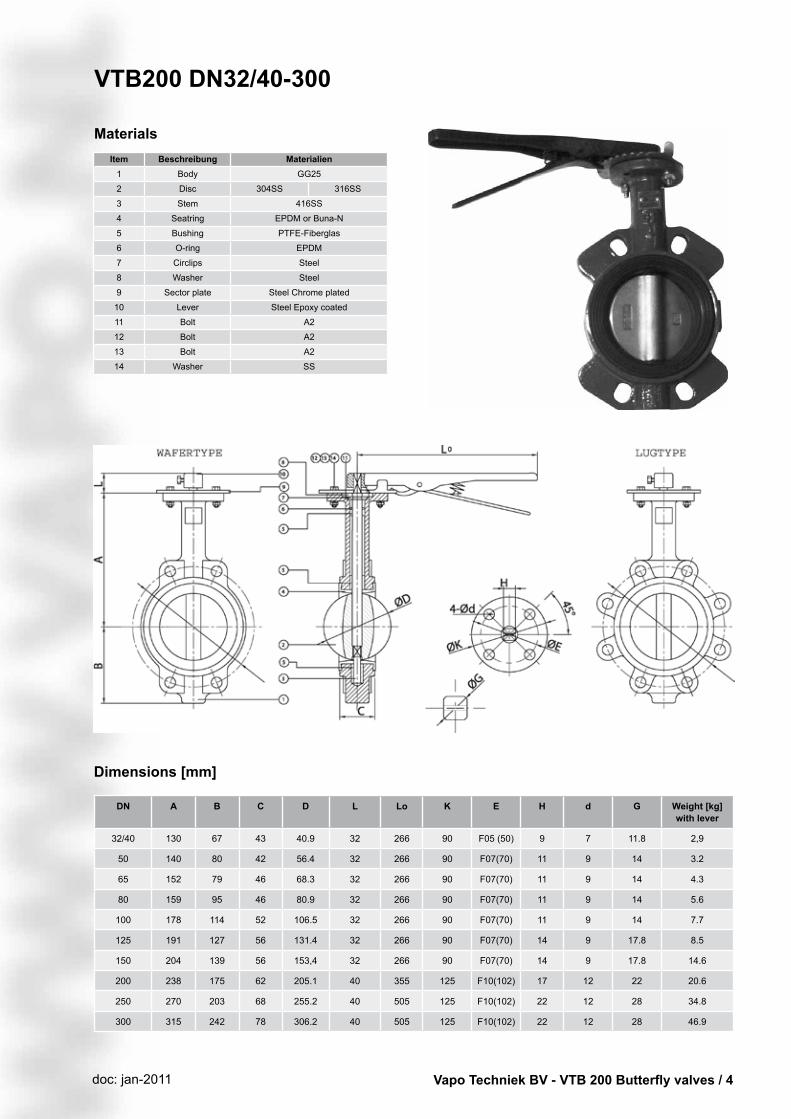
Item Beschreibung Materialien1 Body GG25
2 Disc 304SS 316SS
3 Stem 416SS
4 Seatring EPDMorBuna-N
5 Bushing PTFE-Fiberglas
6 O-ring EPDM
7 Circlips Steel
8 Washer Steel
9 Sectorplate SteelChromeplated
10 Lever SteelEpoxycoated
11 Bolt A2
12 Bolt A2
13 Bolt A2
14 Washer SS
Materials
VTB200 DN32/40-300
Dimensions [mm]
DN A B C D L Lo K E H d G Weight [kg]with lever
32/40 130 67 43 40.9 32 266 90 F05 (50) 9 7 11.8 2,9
50 140 80 42 56.4 32 266 90 F07(70) 11 9 14 3.2
65 152 79 46 68.3 32 266 90 F07(70) 11 9 14 4.3
80 159 95 46 80.9 32 266 90 F07(70) 11 9 14 5.6
100 178 114 52 106.5 32 266 90 F07(70) 11 9 14 7.7
125 191 127 56 131.4 32 266 90 F07(70) 14 9 17.8 8.5
150 204 139 56 153,4 32 266 90 F07(70) 14 9 17.8 14.6
200 238 175 62 205.1 40 355 125 F10(102) 17 12 22 20.6
250 270 203 68 255.2 40 505 125 F10(102) 22 12 28 34.8
300 315 242 78 306.2 40 505 125 F10(102) 22 12 28 46.9

Vapo Techniek BV - VTB 200 Butterfly valves / 5doc: jan-2011
with double acting actuatorDN DW h La Ba Ca Ga H E Weight [kg]
32/40 AP1D 24 137 87 60 41 221 20 4,1
50 AP2D 22 150 103 73 44.5 245 20 4,8
65 AP2D 22 150 103 73 44.5 256 20 5,9
80 AP3D 17 204 120 85 49.5 296 20 8,4
100 AP3D 17 204 120 85 49.5 315 20 10,5
125 AP3.5D 17 230 130 98 53 338 20 12,8
150 AP4D 17 271 145 110 58 366 20 20,4
200 AP4.5D 22 305 172 128 69 398 30 28,9
250 AP5D 25 360 185 140 - 480 30 32,2
300 AP5.5D 22 380 206 160 - 543 30 61,1
with single acting actuatorDN EW h La Ba Ca Ga H E Weight [kg]
32/40 AP2S 24 150 103 73 44.5 257 20 4,8
50 AP3S 17 204 120 85 49.5 277 20 6,6
65 AP3.5S 15 230 130 98 53 297 20 9,2
80 AP3.5S 15 230 130 98 53 323 20 10,5
100 AP4S 15 271 145 110 58 338 20 14,6
125 AP4.5S 14 305 172 128 69 390 30 18,2
150 AP5S 14 360 185 140 - 403 30 28,8
200 AP6S 22 462 230 175 - 490 30 46,5
250 AP8S 15 555 300 215 - 585 50 69,2
300 AP8S 15 555 300 215 - 630 50 95,5
Actuatoraresizedwithanairpressureof6bargandacleanmedia.Mediumpressure6barg.
VTB200 DN32/40-300
Dimensions [mm]
Vapo Techniek BV - VTB 200 Butterfly valves / 6doc: jan-2011
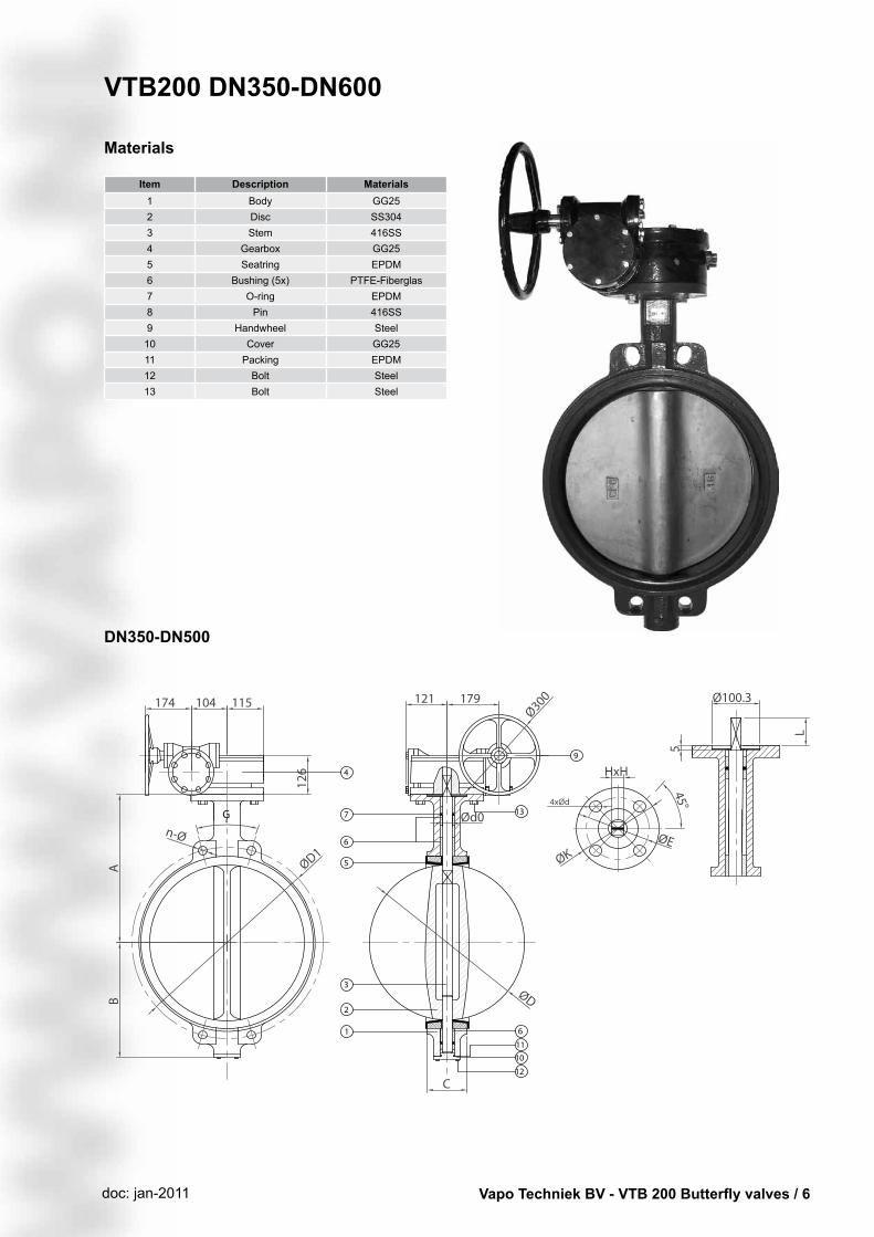
VTB200 DN350-DN600
Materials
Item Description Materials1 Body GG252 Disc SS3043 Stem 416SS4 Gearbox GG255 Seatring EPDM6 Bushing (5x) PTFE-Fiberglas7 O-ring EPDM8 Pin 416SS9 Handwheel Steel
10 Cover GG2511 Packing EPDM12 Bolt Steel13 Bolt Steel
DN350-DN500
G

Vapo Techniek BV - VTB 200 Butterfly valves / 7doc: jan-2011
DN A B C D L K E G H Weight [kg]with gearbox
350 368 267 78 333.3 45 140 F10(102) 22.5° 22 55.7
400 400 309 86.5 389.6 50 197 F14(140) 22.5° 27 93
450 422 328 103.6 440.5 50 197 F14(140) 22.5° 27 113.3
500 480 361 129.8 491.6 57 197 F14(140) 18° 36 176
600 562 459 152 592.5 82 276 F16(165) xxxx 36 236
PN10 PN16 ASA 150
DN n-Ø D1 n-Ø D1 d1 D1
350 4 x 22 460 4 x 26 470 4 x 28.4 476,2
400 4 x 26 515 4 x 30 525 4 x 28.4 539.7
450 4 x 26 565 4 x 30 585 4 x 31.8 577.8
500 4 x 26 620 4 x 33 650 4 x 31.8 635
600 20 x 30 725 20 x 36 770 xxxx xxxx
Dimensions [mm]
DN600 Monoflange
MONOFLANGE
VTB200 DN350-DN600

Vapo Techniek BV - VTB 200 Butterfly valves / 8doc: jan-2011
Dimensions [mm]
with double acting actuator
DN DW h La Ba Ca Ga H E Weight [kg]
350 AP5.5D 100 388 422 160 - 890 30 70,2
400 AP6D 120 468 500 175 - 1020 30 118,9
450 AP8D 120 563 612 215 - 1154 50 153,4
500 AP8D 120 563 612 215 - 1212 50 216,1
600 AP10D 140 750 838 290 - 1540 50 346
with single acting actuator
DN EW h La Ba Ca Ga H E Weight [kg]
350 AP8S 120 563 612 215 - 1100 50 104,3
400 AP10S3 140 750 838 290 - 1378 50 221
450 AP10S4 140 750 838 290 - 1400 50 241,3
500 AP10S 140 750 838 290 - 1458 50 304
600 AP10S6 140 750 838 290 - 1540 50 364
Actuatoraresizedwithanairpressureof6bargandacleanmedia.Mediumpressure6barg.
Remark:Swithoutmeans5Springsoneachsideoftheactuator.S3means3springsoneachside;S4means4springsoneachside,etc.
VTB200 DN350-DN600

Vapo Techniek BV - VTB 200 Butterfly valves / 9doc: jan-2011
VTB200 DN700-DN1200
Materials
Item Description Materials1 Body GG252 Disc 304SS3 Stem 416SS4 Gearbox GG255 Seatring EPDMorNBR6 Bushing PTFE-Fiberglas7 O-ring EPDM8 Pin 416SS9 Woodruff Steel10 Cover GG2511 Packing EPDM12 Bolt Steel13 Bolt Steel14 Handwheel Steel

Vapo Techniek BV - VTB 200 Butterfly valves / 10doc: jan-2011
DN A B C D L ØG H ISO d0 F1 F2 F3 F4 F5 Weight [kg] with Gearbox
700 624 520 152 695 66 895 157 F25 55 165 162 189 183 244 381
800 660 539 163 744,4 66 984 157 F25 55 165 162 189 183 244 465
900 720 656 203 864,7 118 1115 270 F25 75 215 196 220 215 270 831
1000 800 721 216 965 142 1230 270 F25 85 215 196 220 215 270 982
1200 941 864 276 1160,6 154 1511 458 F30 105 215 295 214 310 458 1185
PN10 PN16
DN N-Ø 4-Ød D1 N-Ø 4-Ød D1
700 20-30 4-M27 840 20-36 4-M33 840
750 20-33 4-M30 950 20-39 4-M36 950
900 24-33 4-M30 1050 24-39 4-M36 1050
1000 24-36 4-M33 1160 24-42 4-M39 1170
1200 28-39 4-M36 1380 28-48 4-M45 1390
Dimensions [mm]
VTB200 DN700-DN1200

Vapo Techniek BV - VTB 200 Butterfly valves / 11doc: jan-2011
Assembly and disassembly instructions
Montage1. Connect the body (1) of the valve to a clamp
from the bottom side.2. Mounttheseat(2)inthebody(1).accordingto
the holes. Align the bigger hole on the top of the flangeofthebody(1).
3. MounttheO-ring(4)andthebushing(5)tothebody.
4. Insert the stem (6) in the body (1) through the topflange,tillthestem(6)isequaltotheuperhole of the seatring (2).
5. Mountthedisc(3)intheseatring(2).andpressthe stem down through the disc.
6. Mountthecirclip(7)ontopofthestem(6).7. Attach the stopper plate (8) and screw it to the
topflangeusingthebolts(12).8. Tighten the sector plate (10) with the bolts and
nuts (12) (do not toghten these complete).9. Mountthelever(13)onthestem(6)and
position the sector plate (10) at the same time.10. Tigthen bolts and nuts (12) and tighten the lever
to the stem with the bolt (14).11.Thebutterflyvalveisreadyforinstallation
betweenflanges.
Disassembly1. Connect the valve body (1) to a clamp from the
bottom side.2. If the valve is lever operated, loosen the bolt
(14) und remove the lever (13).3. Loosen the bolts and nuts (12), dismantel the
sector plate (10).4. Ifanytypeofactuatorisused,removethisfirst
from the valve.5. Remove the screws (9) and the stopper plate
(8).6. Disconnect the valve body (1) from the clamp to
remove the stem (6).7. Seccurthebodytotheclampfromthesquare
side of the valve (1).8. Remove the stem (6) from the body after that
the disc (3) and the seatring (2).
Removing the valve from the pipeline1. Stoptheflowofthefluidanddischargethefluit
form the pipeline.2. Shutthevalve100%3. Loosen and remove all the bolts which prevent
removing the valve from the pipeline. 4. Remove the valve by opening the space
betweentheflanges.(ifneededuseanseperator to remove the valve)

Vapo Techniek BV - VTB 200 Butterfly valves / 12doc: jan-2011
Installation instructions
Installing the valves in existing pipelines
1.Inordertomakemountingeasieropentheflangescompletely. If needed with an seperator
2. Disc must be in a 95% closed position.3.Centrethevalvebetweentheflangesandtighten
theboltsandnuts,fixthesebyhand.4.Openthevalvecompletelyandremovetheflange
seperatorbetweentheflanges.5. Tighten the bolts again using hand only.6. After that open and close the valve several times
to ensure a free movement of the valve.7.Tightentheboltsandnutsuntilltheflangestouch
the body of the valve.
Installing the valve in a new pipeline1. Connect the valve wilt bolts between the two
flangesinthepipelinewhilethediscisina95%closed position.
2.Weldtheflangeofthelineonlyattwopoints.3. Remove the valve, make sure that the seatring
stays in a good condition.4.Carefullyweldtheflangeonthelineandwait
for cooling. To avoid heat damage to the rubber seat.Neverweldtheflangewhilethevalveisstillconnected.
5. Using welding gauge apparatus is advised for valves with sizes over DN 200.
6.Mountthebutterflyvalve(95%closed)betweentheflangeswithboltsandnuts.
7. Tighten the bolts using hand only.8.Openandclosethevalveseveraltimestoensure
an free movement. Tighten the bolts and nuts untilltheflangestouchthebodyofthevalve.
DN 50 65 80 100 125 150 200 250 300 350 400 450 500 600
Ød min/ d max 52/62 68/77 82/95 102/118 127/144 152/170 202/225 252/276 303/325 316/356 375/407 415/450 468/505 545/600
ØD min 88 104 120 146 176 200 256 310 368 405 455 500 560 655
[mm]

Vapo Techniek BV - VTB 200 Butterfly valves / 13doc: jan-2011
Additional installation information
Installing the valves near the curves (see diagram) shall cause turbulence and should be avoided.n.
Weldednecktypeflangesareadvised.Otherwisethevalvesmustbecentredbetweentheflanges.
Alwaysinstallthevalvesfurtherfromthecurveequally3to 5 times the diameter of the line. The axis of the stem should be parallel to the line extended from the opposite side of the curve.
Surroundingspacemustbeprovidedbetweentheflangestoinsertthevalve.Thediscmustbeat95%closed position prior to installing the valve.
Using scrap pipes is not recommended. The pipes must not be welded to each other at short intervals. The lines connected to the two sides of the valve must be on the same axis to prevent leakage.
- lines connected to the valves must be centred with each other.
- movement of the disc must be completely open.- line and stem axis must be centred.- theboltsmustbetigteneduntiltheflangestouchthe
valve body.
If the stem must be installed parallel to the ground to accommodatedenseflowingmaterials,lowerpartofthediscshouldopeninthesamedirectionoftheflow.


