13
VTB 200 Butterfly valves
VTB 200Butterfly valves
Vapo Techniek BV, VTB 200 Butterfly valves / 2doc: apr-2008
Address
http://www.vapo.nl
Netherlands
Vapo Techniek BVEsp 2585633 AC Eindhoven
T: +31(0)40 248 10 00F: +31(0)40 248 10 40E: [email protected]
TRADEMARKSFollowing brand names are Dupontregistered trademarks:
- Kalrez®
- Viton®
- Teflon®
- Hypalon®
- BUNA-N®
DISCLAIMERVapo Techniek BV has done itsutmost to ensure that all data in thisdocumentation are correct.However, Vapo Techniek BV acceptsno responsibility for possibleproblems caused by mistakes in thisdocumentation.
’
Table of Contents
VTB200 _________________________________ 3General properties ________________________ 3Specifications ____________________________ 3Seat materials and their application. ___________ 3Cv-values _______________________________ 3Process conditions ________________________ 3Materials ________________________________ 4
VTB200 DN32/40-300______________________ 4VTB200 DN350-DN600 ____________________ 6VTB200 DN700-DN1200 ___________________ 9
Assembly and disassembly instructions _______ 11Installation instructions ____________________ 12Additional installation information ____________ 13
Vapo Techniek BV, VTB 200 Butterfly valves / 3doc: apr-2008
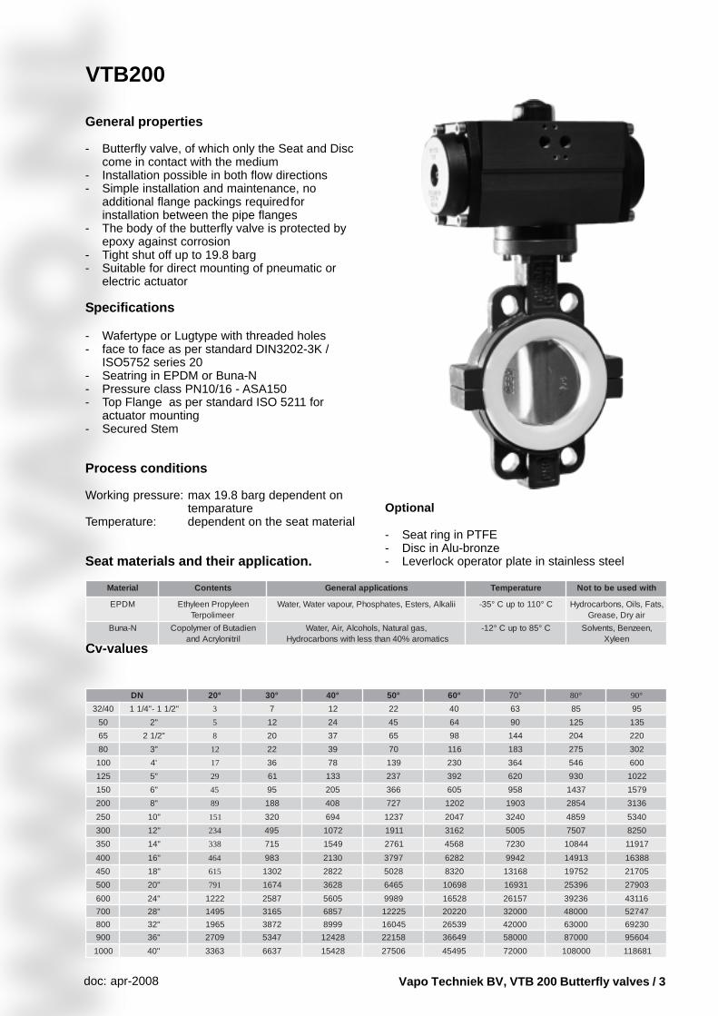
VTB200
General properties
- Butterfly valve, of which only the Seat and Disccome in contact with the medium
- Installation possible in both flow directions- Simple installation and maintenance, no
additional flange packings requiredforinstallation between the pipe flanges
- The body of the butterfly valve is protected byepoxy against corrosion
- Tight shut off up to 19.8 barg- Suitable for direct mounting of pneumatic or
electric actuator
Specifications
- Wafertype or Lugtype with threaded holes- face to face as per standard DIN3202-3K /
ISO5752 series 20- Seatring in EPDM or Buna-N- Pressure class PN10/16 - ASA150- Top Flange as per standard ISO 5211 for
actuator mounting- Secured Stem
Process conditions
Working pressure: max 19.8 barg dependent ontemparature
Temperature: dependent on the seat material
Seat materials and their application.
lairetaM stnetnoC snoitacilppalareneG erutarepmeT htiwdesuebottoN
MDPE neelyporPneelyhtEreemilopreT
iilaklA,sretsE,setahpsohP,ruopavretaW,retaW C°011otpuC°53- ,staF,sliO,snobracordyHriayrD,esaerG
N-anuB neidatuBforemylopoClirtinolyrcAdna
,saglarutaN,slohoclA,riA,retaWscitamora%04nahtsselhtiwsnobracordyH
C°58otpuC°21- ,neezneB,stnevloSneelyX
Optional
- Seat ring in PTFE- Disc in Alu-bronze- Leverlock operator plate in stainless steel
Cv-values
ND °02 °03 °04 °05 °06 °07 °08 °09
04/23 "2/11-"4/11 3 7 21 22 04 36 58 59
05 "2 5 21 42 54 46 09 521 531
56 "2/12 8 02 73 56 89 441 402 022
08 "3 21 22 93 07 611 381 572 203
001 '4 71 63 87 931 032 463 645 006
521 "5 92 16 331 732 293 026 039 2201
051 "6 54 59 502 663 506 859 7341 9751
002 "8 98 881 804 727 2021 3091 4582 6313
052 "01 151 023 496 7321 7402 0423 9584 0435
003 "21 432 594 2701 1191 2613 5005 7057 0528
053 "41 833 517 9451 1672 8654 0327 44801 71911
004 "61 464 389 0312 7973 2826 2499 31941 88361
054 "81 516 2031 2282 8205 0238 86131 25791 50712
005 "02 197 4761 8263 5646 89601 13961 69352 30972
006 "42 2221 7852 5065 9899 82561 75162 63293 61134
007 "82 5941 5613 7586 52221 02202 00023 00084 74725
008 "23 5691 2783 9998 54061 93562 00024 00036 03296
009 "63 9072 7435 82421 85122 94663 00085 00078 40659
0001 "04 3633 7366 82451 60572 59454 00027 000801 186811
Vapo Techniek BV, VTB 200 Butterfly valves / 4doc: apr-2008
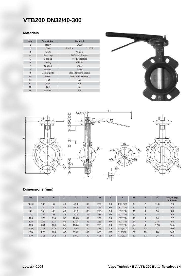
metI noitpircseD lairetaM
1 ydoB 52GG
2 csiD SS403 SS613
3 metS SS614
4 gnirtaeS N-anuBroMDPE
5 gniraeB salgrebif-EFTP
6 gnir-O MDPE
7 spilcriC leetS
8 rehsaW leetS
9 etalprotceS detalpemorhC,leetS
01 reveL detaocyxopeleetS
11 tloB 2A
21 tloB 2A
31 tuN 2A
41 rehsaW SS
Materials
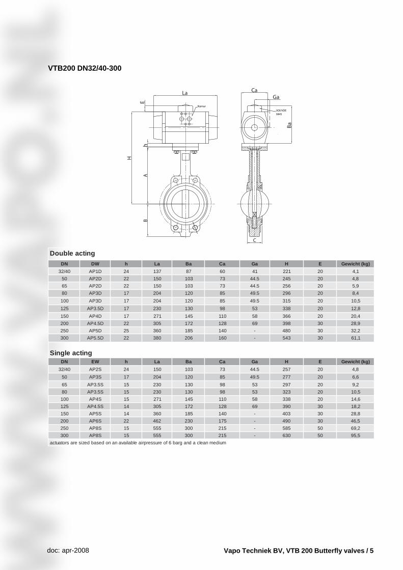
VTB200 DN32/40-300
Dimensions (mm)
ND A B C D L oL K E H d G )gk(thgieWrevel.lcni
04/23 031 76 34 9.04 23 662 09 )05(50F 9 7 8.11 9,2
05 041 08 24 4.65 23 662 09 )07(70F 11 9 41 2.3
56 251 98 64 3.86 23 662 09 )07(70F 11 9 41 3.4
08 951 59 64 9.08 23 662 09 )07(70F 11 9 41 6.5
001 871 411 25 5.601 23 662 09 )07(70F 11 9 41 7.7
521 191 721 65 4.131 23 662 09 )07(70F 41 9 8.71 5.8
051 402 931 65 4,351 23 662 09 )07(70F 41 9 8.71 6.41
002 832 571 26 1.502 04 553 521 )201(01F 71 21 22 6.02
052 072 302 86 2.552 04 505 521 )201(01F 22 21 82 8.43
003 513 242 87 2.603 04 505 521 )201(01F 22 21 82 9.64
Vapo Techniek BV, VTB 200 Butterfly valves / 5doc: apr-2008
gnitcaelbuoDND WD h aL aB aC aG H E )gk(thciweG
04/23 D1PA 42 731 78 06 14 122 02 1,4
05 D2PA 22 051 301 37 5.44 542 02 8,4
56 D2PA 22 051 301 37 5.44 652 02 9,5
08 D3PA 71 402 021 58 5.94 692 02 4,8
001 D3PA 71 402 021 58 5.94 513 02 5,01
521 D5.3PA 71 032 031 89 35 833 02 8,21
051 D4PA 71 172 541 011 85 663 02 4,02
002 D5.4PA 22 503 271 821 96 893 03 9,82
052 D5PA 52 063 581 041 - 084 03 2,23
003 D5.5PA 22 083 602 061 - 345 03 1,16
gnitcaelgniSND WE h aL aB aC aG H E )gk(thciweG
04/23 S2PA 42 051 301 37 5.44 752 02 8,4
05 S3PA 71 402 021 58 5.94 772 02 6,6
56 S5.3PA 51 032 031 89 35 792 02 2,9
08 S5.3PA 51 032 031 89 35 323 02 5,01
001 S4PA 51 172 541 011 85 833 02 6,41
521 S5.4PA 41 503 271 821 96 093 03 2,81
051 S5PA 41 063 581 041 - 304 03 8,82
002 S6PA 22 264 032 571 - 094 03 5,64
052 S8PA 51 555 003 512 - 585 05 2,96
003 S8PA 51 555 003 512 - 036 05 5,59
muidemnaelcadnagrab6foerusserpriaelbaliavananodesabdeziserasrotautca
VTB200 DN32/40-300
Vapo Techniek BV, VTB 200 Butterfly valves / 6doc: apr-2008
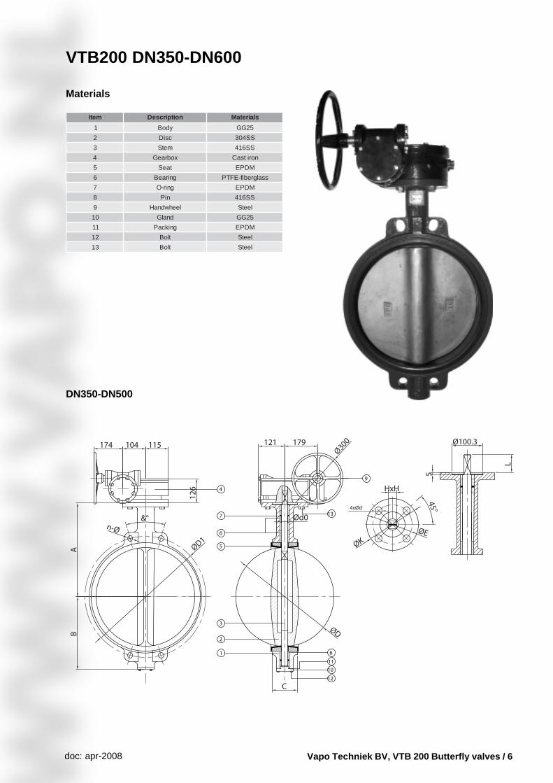
VTB200 DN350-DN600
Materials
metI noitpircseD slairetaM
1 ydoB 52GG
2 csiD SS403
3 metS SS614
4 xobraeG noritsaC
5 taeS MDPE
6 gniraeB ssalgrebif-EFTP
7 gnir-O MDPE
8 niP SS614
9 leehwdnaH leetS
01 dnalG 52GG
11 gnikcaP MDPE
21 tloB leetS
31 tloB leetS
DN350-DN500
Vapo Techniek BV, VTB 200 Butterfly valves / 7doc: apr-2008
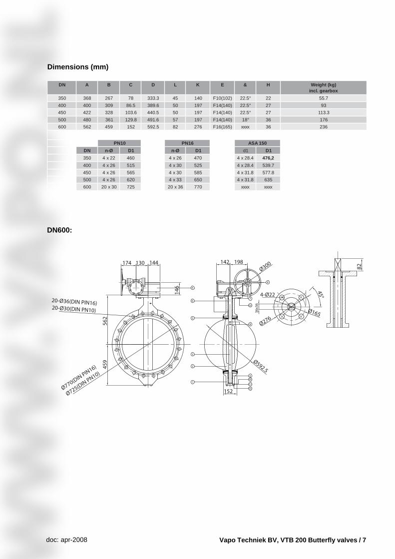
ND A B C D L K E & H )gk(thgieWxobraeg.lcni
053 863 762 87 3.333 54 041 )201(01F °5.22 22 7.55
004 004 903 5.68 6.983 05 791 )041(41F °5.22 72 39
054 224 823 6.301 5.044 05 791 )041(41F °5.22 72 3.311
005 084 163 8.921 6.194 75 791 )041(41F °81 63 671
006 265 954 251 5.295 28 672 )561(61F xxxx 63 632
01NP 61NP 051ASA
ND Ø-n 1D Ø-n 1D 1d 1D
053 22x4 064 62x4 074 4.82x4 2,674
004 62x4 515 03x4 525 4.82x4 7.935
054 62x4 565 03x4 585 8.13x4 8.775
005 62x4 026 33x4 056 8.13x4 536
006 03x02 527 63x02 077 xxxx xxxx
Dimensions (mm)
DN600:
Vapo Techniek BV, VTB 200 Butterfly valves / 8doc: apr-2008
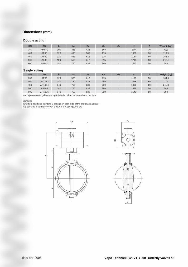
Dimensions (mm)
gnitcaelbuoD
ND WD h aL aB aC aG H E )gk(thgieW
053 D5.5PA 001 883 224 061 - 098 03 2,07
004 D6PA 021 864 005 571 - 0201 03 9,811
054 D8PA 021 365 216 512 - 4511 05 4,351
005 D8PA 021 365 216 512 - 2121 05 1,612
006 D01PA 041 057 838 092 - 0451 05 643
gnitcaelgniSND WE h aL aB aC aG H E )gk(thgieW
053 S8PA 021 365 216 512 - 0011 05 3,401
004 3S01PA 041 057 838 092 - 8731 05 122
054 4S01PA 041 057 838 092 - 0041 05 3,142
005 S01PA 041 057 838 092 - 8541 05 403
006 6S01PA 041 057 838 092 - 0451 05 463
muidemnoohcsneene,kurdthculgrab6podreesabegettoorggnivjirdnaa
:skramerrotautcacitamuenpehtfoedishcaenosgnirps5otstnioplanoitiddatuohtiwS
znecte,sgnirps4ot4S,edishcaenosgnirps3otstniop3S
Vapo Techniek BV, VTB 200 Butterfly valves / 9doc: apr-2008
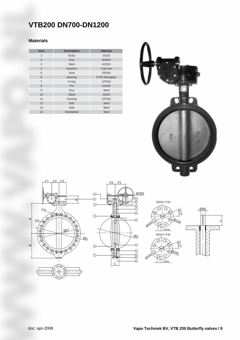
VTB200 DN700-DN1200
Materials
metI noitpircseD lairetaM
1 ydoB 52GG
2 csiD SS403
3 metS SS614
4 xobraeG norItsaC
5 taeS MDPE
6 gniraeB ssalgrebif-EFTP
7 gnir-O MDPE
8 niP SS614
9 yeK leetS
01 dnalG 52GG
11 gnikcaP MDPE
21 tloB leetS
31 tloB leetS
41 leehwdnaH leetS
Vapo Techniek BV, VTB 200 Butterfly valves / 10doc: apr-2008
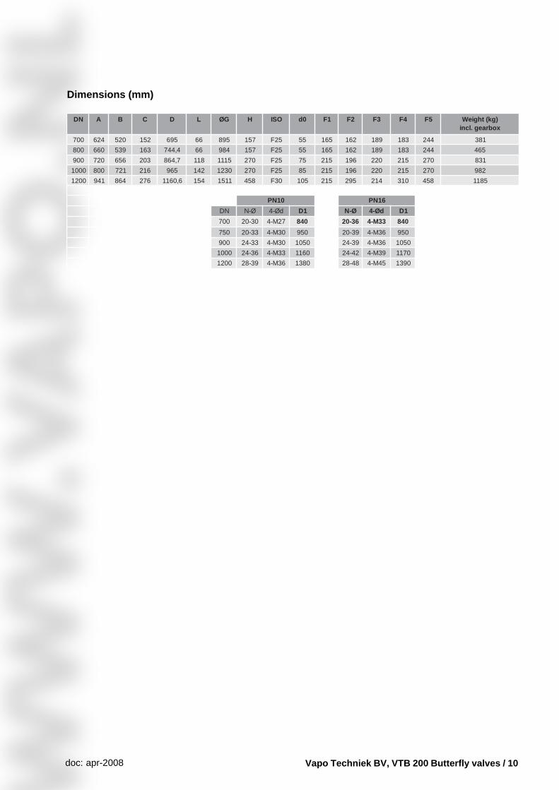
ND A B C D L GØ H OSI 0d 1F 2F 3F 4F 5F )gk(thgieWxobraeg.lcni
007 426 025 251 596 66 598 751 52F 55 561 261 981 381 442 183
008 066 935 361 4,447 66 489 751 52F 55 561 261 981 381 442 564
009 027 656 302 7,468 811 5111 072 52F 57 512 691 022 512 072 138
0001 008 127 612 569 241 0321 072 52F 58 512 691 022 512 072 289
0021 149 468 672 6,0611 451 1151 854 03F 501 512 592 412 013 854 5811
01NP 61NP
ND Ø-N dØ-4 1D Ø-N dØ-4 1D
007 03-02 72M-4 048 63-02 33M-4 048
057 33-02 03M-4 059 93-02 63M-4 059
009 33-42 03M-4 0501 93-42 63M-4 0501
0001 63-42 33M-4 0611 24-42 93M-4 0711
0021 93-82 63M-4 0831 84-82 54M-4 0931
Dimensions (mm)
Vapo Techniek BV, VTB 200 Butterfly valves / 11doc: apr-2008
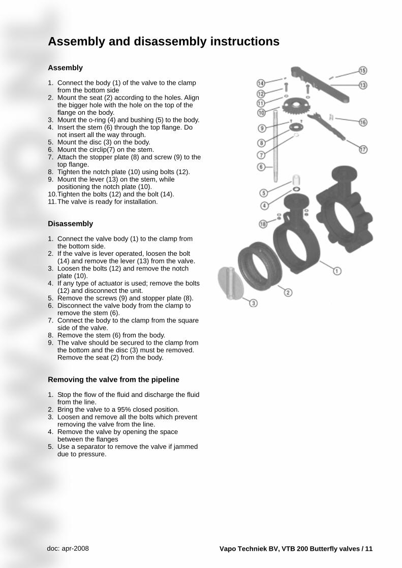
Assembly and disassembly instructions
Assembly
1. Connect the body (1) of the valve to the clampfrom the bottom side
2. Mount the seat (2) according to the holes. Alignthe bigger hole with the hole on the top of theflange on the body.
3. Mount the o-ring (4) and bushing (5) to the body.4. Insert the stem (6) through the top flange. Do
not insert all the way through.5. Mount the disc (3) on the body.6. Mount the circlip(7) on the stem.7. Attach the stopper plate (8) and screw (9) to the
top flange.8. Tighten the notch plate (10) using bolts (12).9. Mount the lever (13) on the stem, while
positioning the notch plate (10).10.Tighten the bolts (12) and the bolt (14).11.The valve is ready for installation.
Disassembly
1. Connect the valve body (1) to the clamp fromthe bottom side.
2. If the valve is lever operated, loosen the bolt(14) and remove the lever (13) from the valve.
3. Loosen the bolts (12) and remove the notchplate (10).
4. If any type of actuator is used; remove the bolts(12) and disconnect the unit.
5. Remove the screws (9) and stopper plate (8).6. Disconnect the valve body from the clamp to
remove the stem (6).7. Connect the body to the clamp from the square
side of the valve.8. Remove the stem (6) from the body.9. The valve should be secured to the clamp from
the bottom and the disc (3) must be removed.Remove the seat (2) from the body.
Removing the valve from the pipeline
1. Stop the flow of the fluid and discharge the fluidfrom the line.
2. Bring the valve to a 95% closed position.3. Loosen and remove all the bolts which prevent
removing the valve from the line.4. Remove the valve by opening the space
between the flanges5. Use a separator to remove the valve if jammed
due to pressure.
Vapo Techniek BV, VTB 200 Butterfly valves / 12doc: apr-2008
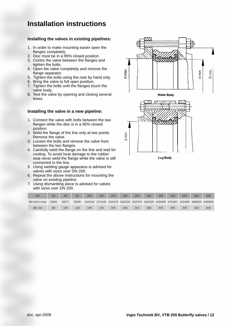
Installation instructions
Installing the valves in existing pipelines:
1. In order to make mounting easier open theflanges completely.
2. Disc must be in a 95% closed position.3. Centre the valve between the flanges and
tighten the bolts.4. Open the valve completely and remove the
flange separator.5. Tighten the bolts using the nuts by hand only.6. Bring the valve to full open position.7. Tighten the bolts until the flanges touch the
valve body.8. Test the valve by opening and closing several
times.
Installing the valve in a new pipeline:
1. Connect the valve with bolts between the twoflanges while the disc is in a 95% closedposition.
2. Weld the flange of the line only at two points.Remove the valve.
3. Loosen the bolts and remove the valve frombetween the two flanges.
4. Carefully weld the flange on the line and wait forcooling. To avoid heat damage to the rubberseat never weld the flange while the valve is stillconnected to the line.
5. Using welding gauge apparatus is advised forvalves with sizes over DN 200.
6. Repeat the above instructions for mounting thevalve on existing pipeline.
7. Using dismantling piece is advised for valveswith sizes over DN 200.
ND 05 56 08 001 521 051 002 052 003 053 004 054 005 006
xamd/nimdØ 26/25 77/86 59/28 811/201 441/721 071/251 522/202 672/252 523/303 653/613 704/573 054/514 505/864 006/545
nimDØ 88 401 021 641 671 002 652 013 863 504 554 005 065 556
Vapo Techniek BV, VTB 200 Butterfly valves / 13doc: apr-2008
Additional installation information
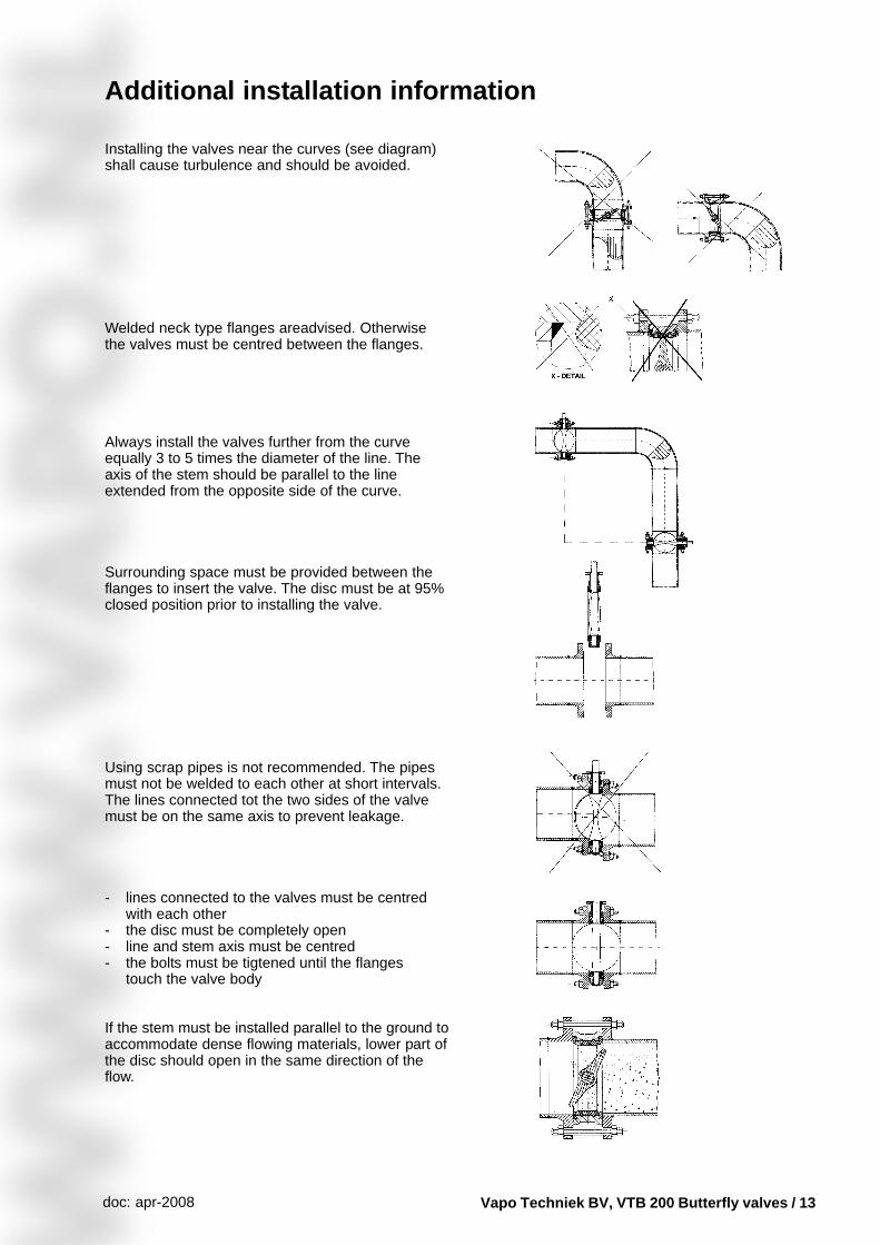
Installing the valves near the curves (see diagram)shall cause turbulence and should be avoided.
Welded neck type flanges areadvised. Otherwisethe valves must be centred between the flanges.
Always install the valves further from the curveequally 3 to 5 times the diameter of the line. Theaxis of the stem should be parallel to the lineextended from the opposite side of the curve.
Surrounding space must be provided between theflanges to insert the valve. The disc must be at 95%closed position prior to installing the valve.
Using scrap pipes is not recommended. The pipesmust not be welded to each other at short intervals.The lines connected tot the two sides of the valvemust be on the same axis to prevent leakage.
- lines connected to the valves must be centredwith each other
- the disc must be completely open- line and stem axis must be centred- the bolts must be tigtened until the flanges
touch the valve body
If the stem must be installed parallel to the ground toaccommodate dense flowing materials, lower part ofthe disc should open in the same direction of theflow.


