1 | 028-6111-00 November 2015 CONTENTS Configuring and Status Display Instructions 2 Status display 2 User Interface 4 Local keypad interface 4 Dual occupied setpoints adjustment 5 Single occupied setpoints adjustment 5 Unoccupied and stand-by setpoints adjustments 5 Mode button menu sequence. 5 Installer Configuration Parameter Menu 7 Configuration interface 7 VTR7300 Series User Interface Guide November 2015
Transcript
1 | 028-6111-00 November 2015
CONTENTS
Configuring and Status Display Instructions 2 Status display 2
User Interface 4 Local keypad interface 4 Dual occupied setpoints adjustment 5 Single occupied setpoints adjustment 5 Unoccupied and stand-by setpoints adjustments 5 Mode button menu sequence. 5
Installer Configuration Parameter Menu 7 Configuration interface 7
VTR7300 Series User Interface Guide
November 2015
2 | 028-6111-00 November 2015
CONFIGURING AND STATUS DISPLAY INSTRUCTIONS
Status display The VTR73xxA Terminal Equipment Controller features a two-line, eight-character
display. There is a low-level backlight that is always active and can only be seen at night.
When left unattended, the Terminal Equipment Controller has an auto scrolling display
that shows the status of the system. There is an option in the configuration menu to
lockout the scrolling display and to only display the room temperature and conditional
outdoor temperature to the user. With this option enabled, no local status of mode,
occupancy and relative humidity is shown.
Each item scrolls individually with the back lighting in low level mode. Pressing any key
will cause the back light to come on to high level. When left unattended for 10 seconds
after changes are made, the display will resume automatic status display scrolling.
To activate the back light to high level, press any key on the front panel. The back light
display will return to low level when the Terminal Equipment Controller is left unattended
for 45 seconds.
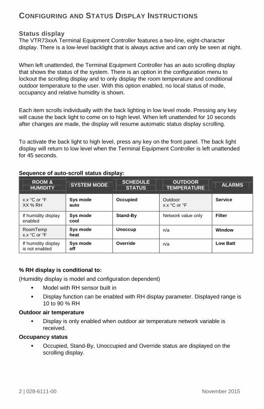
Sequence of auto-scroll status display:
ROOM & HUMIDITY
SYSTEM MODE SCHEDULE
STATUS OUTDOOR
TEMPERATURE ALARMS
x.x °C or °F XX % RH
Sys mode auto
Occupied
Outdoor x.x °C or °F
Service
If humidity display enabled
Sys mode cool
Stand-By
Network value only
Filter
RoomTemp x.x °C or °F
Sys mode heat
Unoccup
n/a Window
If humidity display is not enabled
Sys mode off
Override
n/a Low Batt
% RH display is conditional to:
(Humidity display is model and configuration dependent)
Model with RH sensor built in
Display function can be enabled with RH display parameter. Displayed range is
10 to 90 % RH
Outdoor air temperature
Display is only enabled when outdoor air temperature network variable is
received.
Occupancy status
Occupied, Stand-By, Unoccupied and Override status are displayed on the
scrolling display.
3 | 028-6111-00 November 2015
Alarms
If alarms are detected, they will automatically be displayed at the end of the
scrolling status display.
When an alarm message is displayed, the backlit screen will illuminate at the
same time as the message and shut off during the rest of the status display.
A maximum of two alarms can appear at any given time. The priority for the
alarms are as follows:
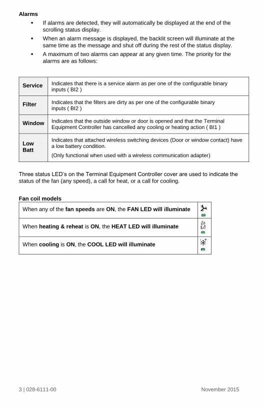
Three status LED’s on the Terminal Equipment Controller cover are used to indicate the
status of the fan (any speed), a call for heat, or a call for cooling.
Fan coil models
When any of the fan speeds are ON, the FAN LED will illuminate
When heating & reheat is ON, the HEAT LED will illuminate
When cooling is ON, the COOL LED will illuminate
Service Indicates that there is a service alarm as per one of the configurable binary inputs ( BI2 )
Filter Indicates that the filters are dirty as per one of the configurable binary inputs ( BI2 )
Window Indicates that the outside window or door is opened and that the Terminal Equipment Controller has cancelled any cooling or heating action ( BI1 )
Low Batt
Indicates that attached wireless switching devices (Door or window contact) have a low battery condition. (Only functional when used with a wireless communication adapter)
4 | 028-6111-00 November 2015
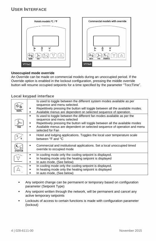
USER INTERFACE
Unoccupied mode override An Override can be made on commercial models during an unoccupied period. If the
Override option is enabled in the lockout configuration, pressing the middle override
button will resume occupied setpoints for a time specified by the parameter “ToccTime”.
Local keypad interface
Any setpoint change can be permanent or temporary based on configuration
parameter (Setpoint Type)
Any setpoint written through the network, will be permanent and cancel any
active temporary setpoints
Lockouts of access to certain functions is made with configuration parameter
(lockout)
Is used to toggle between the different system modes available as per sequence and menu selected.
Repetitively pressing the button will toggle between all the available modes. Available menus are dependent on selected sequence of operation.
Is used to toggle between the different fan modes available as per the sequence and menu selected
Repetitively pressing the button will toggle between all the available modes Available menus are dependent on selected sequence of operation and menu
selected for Fan
Hotel and lodging applications. Toggles the local user temperature scale
between °F and °C
Commercial and institutional applications. Set a local unoccupied timed
override to occupied mode
In cooling mode only the cooling setpoint is displayed, In heating mode only the heating setpoint is displayed In auto mode, (See below)
In cooling mode only the cooling setpoint is displayed, In heating mode only the heating setpoint is displayed In auto mode, (See below)
Heat/Cool setpoint toggle with MODE button to be active only in AUTO mode.
If cooling, heating or off mode is active, function is disabled.
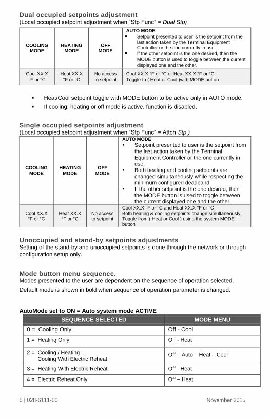
Single occupied setpoints adjustment (Local occupied setpoint adjustment when “Stp Func” = Attch Stp )
Unoccupied and stand-by setpoints adjustments Setting of the stand-by and unoccupied setpoints is done through the network or through
configuration setup only.
Mode button menu sequence. Modes presented to the user are dependent on the sequence of operation selected.
Default mode is shown in bold when sequence of operation parameter is changed.
AutoMode set to ON = Auto system mode ACTIVE
SEQUENCE SELECTED MODE MENU
0 = Cooling Only Off - Cool
1 = Heating Only Off - Heat
2 = Cooling / Heating
Cooling With Electric Reheat Off – Auto – Heat – Cool
3 = Heating With Electric Reheat Off - Heat
4 = Electric Reheat Only Off – Heat
COOLING MODE
HEATING MODE
OFF MODE
AUTO MODE
Setpoint presented to user is the setpoint from the last action taken by the Terminal Equipment Controller or the one currently in use.
If the other setpoint is the one desired, then the MODE button is used to toggle between the current
displayed one and the other.
Cool XX.X °F or °C
Heat XX.X °F or °C
No access to setpoint
Cool XX.X °F or °C or Heat XX.X °F or °C Toggle to ( Heat or Cool )with MODE button
COOLING MODE
HEATING MODE
OFF MODE
AUTO MODE
Setpoint presented to user is the setpoint from the last action taken by the Terminal Equipment Controller or the one currently in use.
Both heating and cooling setpoints are changed simultaneously while respecting the minimum configured deadband
If the other setpoint is the one desired, then the MODE button is used to toggle between the current displayed one and the other.
Cool XX.X °F or °C
Heat XX.X °F or °C
No access to setpoint
Cool XX.X °F or °C and Heat XX.X °F or °C Both heating & cooling setpoints change simultaneously Toggle from ( Heat or Cool ) using the system MODE button
6 | 028-6111-00 November 2015
AutoMode set to OFF = Auto system mode NOT ACTIVE
SEQUENCE SELECTED MODE MENU
0 = Cooling Only Off - Cool
1 = Heating Only Off - Heat
2 = Cooling / Heating
Cooling With Electric Reheat Off – Heat – Cool
3 = Heating With Electric Reheat Off - Heat
4 = Electric Reheat Only Off – Heat
Available fan button menu sequences
FAN BUTTON
MENU
CONFIGURATION
MENU PRESENTED ARE DEPENDENT ON MODEL USED
AND SEQUENCE OF OPERATION SELECTED
DEFAULT VALUE
WHEN SEQUENCE
TOGGLED
0 Low-Med-High 3 Speed configuration using 3 fan relays ( L-M-H ) High
1 Low-High 2 Speed configuration using 2 fan relays ( L-H ) High
2 Low-Med-
High-Auto
3 Speed configuration with Auto fan speed mode using
3 fan relays ( L-M-H-A ) High
3 Low-High-Auto 2 Speed configuration with Auto fan speed mode using
2 fan relays ( L-H-A ) High
4 On-Auto Single Speed configuration. Auto is for Fan on demand /
On is On all the time Auto
Auto speed fan mode is also offered in heating mode applications; it will not have any
effect on dehumidification. It will strictly be used for noise comfort issues.
Auto Speed Fan Mode operation for sequences 2 and 3 is dependent on Auto Fan
parameter. When Auto Fan is set to:
AS (Default) = Auto Speed during occupied periods. Fan is always on during
occupied periods. Low, medium and high speeds operate on temperature offset
from setpoint.
AS AD = Auto Speed / Auto Demand during occupied periods.
o Medium and high speeds operate on temperature offset from setpoint.
o Low speed operates on demand and will shut down when no
demand is present.
7 | 028-6111-00 November 2015
INSTALLER CONFIGURATION PARAMETER MENU
Configuration can be done through the network or locally at the Terminal Equipment
Controller.
To enter configuration, press and hold the middle button (°C/°F or Override) for
8 seconds.
If a password lockout is active, “Password” is prompted. Enter password value
using the “up” and “down” arrows and press the middle button again to gain
access to all configuration properties of the Terminal Equipment Controller.
Entering a wrong password will prevent local access to the configuration menu.
Press the same middle button repetitively to scroll between all the available
parameters.
Use the up and down key to change the parameter to the desired value.
To acknowledge and save the new value, press the middle button again.
The next parameter will now be displayed.
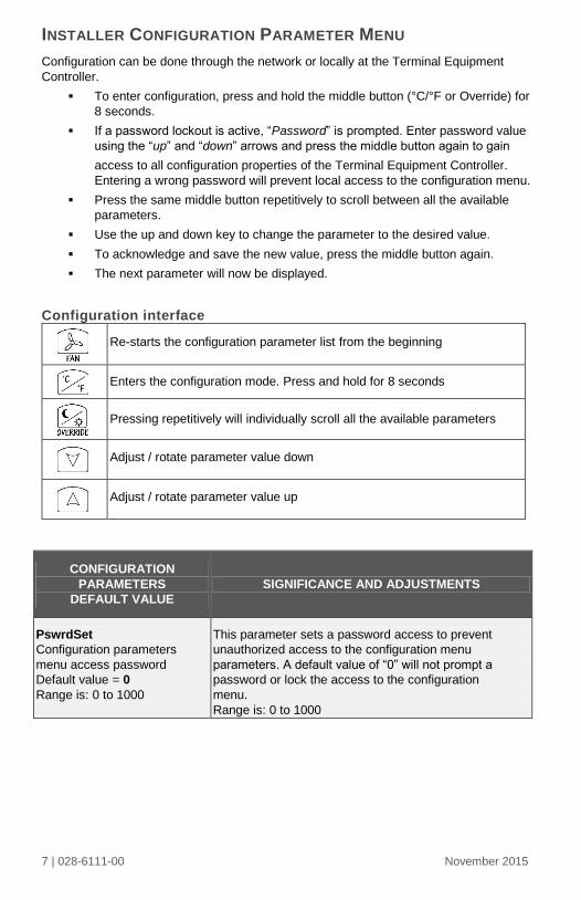
Configuration interface
CONFIGURATION
PARAMETERS
DEFAULT VALUE
SIGNIFICANCE AND ADJUSTMENTS
PswrdSet
Configuration parameters
menu access password
Default value = 0
Range is: 0 to 1000
This parameter sets a password access to prevent
unauthorized access to the configuration menu
parameters. A default value of “0” will not prompt a
password or lock the access to the configuration
menu.
Range is: 0 to 1000
Re-starts the configuration parameter list from the beginning
Enters the configuration mode. Press and hold for 8 seconds
Pressing repetitively will individually scroll all the available parameters
Adjust / rotate parameter value down
Adjust / rotate parameter value up
8 | 028-6111-00 November 2015
Com Addr
Terminal Equipment
Controller networking address
Default value = 254
Range is: 0 to 254
Conditional parameter to BACnet™ MS-TP models
VTR73xxX5x00B
Conditional parameter to Wireless models
VTR73xxX5x00W
For BACnet™ MS-TP models, the valid range is from 1 to 127. Default value of 254 disables BACnet™ communication for the Terminal Equipment Controller. For wireless models, the valid range is 0 to 254 with a maximum of 30 Terminal Equipment Controller per VWG
PAN ID
Personal Area Network
Identification
Default value = 0
Range is: 0 to 1000
Conditional parameter to Wireless models
VTR73xxX5x00W
This parameter will only appear when a wireless
network adapter is present. If the Terminal Equipment
Controller is installed as a stand-alone unit or with a
BACnet™ or Echelon™ adapter, this parameter will
not be used or displayed.
This parameter (Personal Area Network Identification)
is used to link specific Terminal Equipment
Controllers to a single specific Viconics wireless
gateway (VWG). For every Terminal Equipment
Controller reporting to a gateway (maximum of 30
Terminal Equipment Controllers per gateway), be
sure you set the SAME PAN ID value both on the
gateway and the Terminal Equipment Controller(s).
The default value of 0 is NOT a valid PAN ID.
The valid range of available PAN ID is from 1 to 1000.
Range 1 to 500 for centralized networked applications
using a VWG or a Jace with the wireless stat driver
Range 501 to 1000 is for stand-alone applications
where no VWG or Jace with the wireless stat driver is
used.
9 | 028-6111-00 November 2015
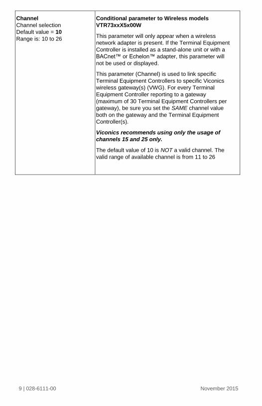
Channel
Channel selection
Default value = 10
Range is: 10 to 26
Conditional parameter to Wireless models
VTR73xxX5x00W
This parameter will only appear when a wireless
network adapter is present. If the Terminal Equipment
Controller is installed as a stand-alone unit or with a
BACnet™ or Echelon™ adapter, this parameter will
not be used or displayed.
This parameter (Channel) is used to link specific
Terminal Equipment Controllers to specific Viconics
wireless gateway(s) (VWG). For every Terminal
Equipment Controller reporting to a gateway
(maximum of 30 Terminal Equipment Controllers per
gateway), be sure you set the SAME channel value
both on the gateway and the Terminal Equipment
Controller(s).
Viconics recommends using only the usage of
channels 15 and 25 only.
The default value of 10 is NOT a valid channel. The
valid range of available channel is from 11 to 26
10 | 028-6111-00 November 2015
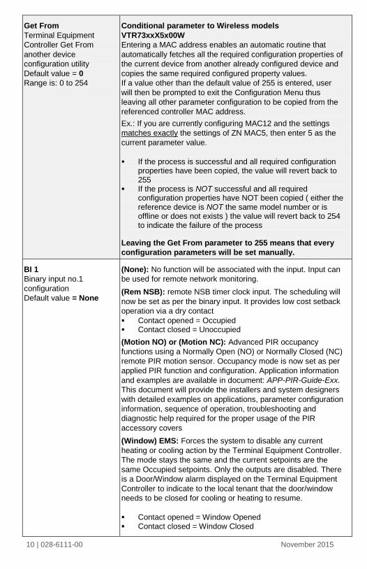
Get From
Terminal Equipment
Controller Get From
another device
configuration utility
Default value = 0
Range is: 0 to 254
Conditional parameter to Wireless models
VTR73xxX5x00W
Entering a MAC address enables an automatic routine that
automatically fetches all the required configuration properties of
the current device from another already configured device and
copies the same required configured property values.
If a value other than the default value of 255 is entered, user
will then be prompted to exit the Configuration Menu thus
leaving all other parameter configuration to be copied from the
referenced controller MAC address.
Ex.: If you are currently configuring MAC12 and the settings
matches exactly the settings of ZN MAC5, then enter 5 as the
current parameter value.
If the process is successful and all required configuration properties have been copied, the value will revert back to 255
If the process is NOT successful and all required configuration properties have NOT been copied ( either the reference device is NOT the same model number or is offline or does not exists ) the value will revert back to 254 to indicate the failure of the process
Leaving the Get From parameter to 255 means that every
configuration parameters will be set manually.
BI 1
Binary input no.1
configuration
Default value = None
(None): No function will be associated with the input. Input can
be used for remote network monitoring.
(Rem NSB): remote NSB timer clock input. The scheduling will
now be set as per the binary input. It provides low cost setback
operation via a dry contact
Contact opened = Occupied Contact closed = Unoccupied
(Motion NO) or (Motion NC): Advanced PIR occupancy
functions using a Normally Open (NO) or Normally Closed (NC)
remote PIR motion sensor. Occupancy mode is now set as per
applied PIR function and configuration. Application information
and examples are available in document: APP-PIR-Guide-Exx.
This document will provide the installers and system designers
with detailed examples on applications, parameter configuration
information, sequence of operation, troubleshooting and
diagnostic help required for the proper usage of the PIR
accessory covers
(Window) EMS: Forces the system to disable any current
heating or cooling action by the Terminal Equipment Controller.
The mode stays the same and the current setpoints are the
same Occupied setpoints. Only the outputs are disabled. There
is a Door/Window alarm displayed on the Terminal Equipment
Controller to indicate to the local tenant that the door/window
needs to be closed for cooling or heating to resume.
Contact opened = Window Opened Contact closed = Window Closed
11 | 028-6111-00 November 2015
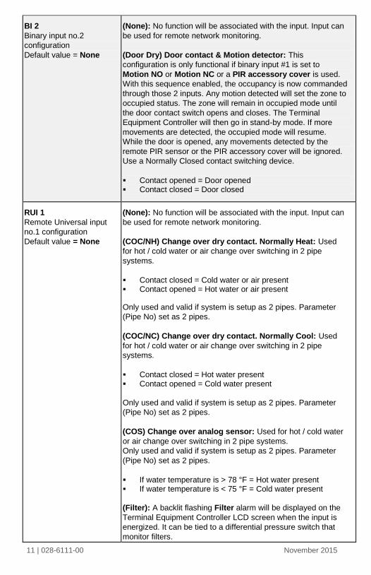
BI 2
Binary input no.2
configuration
Default value = None
(None): No function will be associated with the input. Input can
be used for remote network monitoring.
(Door Dry) Door contact & Motion detector: This
configuration is only functional if binary input #1 is set to
Motion NO or Motion NC or a PIR accessory cover is used.
With this sequence enabled, the occupancy is now commanded
through those 2 inputs. Any motion detected will set the zone to
occupied status. The zone will remain in occupied mode until
the door contact switch opens and closes. The Terminal
Equipment Controller will then go in stand-by mode. If more
movements are detected, the occupied mode will resume.
While the door is opened, any movements detected by the
remote PIR sensor or the PIR accessory cover will be ignored.
Use a Normally Closed contact switching device.
Contact opened = Door opened Contact closed = Door closed
RUI 1
Remote Universal input
no.1 configuration
Default value = None
(None): No function will be associated with the input. Input can
be used for remote network monitoring.
(COC/NH) Change over dry contact. Normally Heat: Used
for hot / cold water or air change over switching in 2 pipe
systems.
Contact closed = Cold water or air present Contact opened = Hot water or air present
Only used and valid if system is setup as 2 pipes. Parameter
(Pipe No) set as 2 pipes.
(COC/NC) Change over dry contact. Normally Cool: Used
for hot / cold water or air change over switching in 2 pipe
systems.
Contact closed = Hot water present Contact opened = Cold water present
Only used and valid if system is setup as 2 pipes. Parameter
(Pipe No) set as 2 pipes.
(COS) Change over analog sensor: Used for hot / cold water
or air change over switching in 2 pipe systems.
Only used and valid if system is setup as 2 pipes. Parameter
(Pipe No) set as 2 pipes.
If water temperature is > 78 °F = Hot water present If water temperature is < 75 °F = Cold water present
(Filter): A backlit flashing Filter alarm will be displayed on the
Terminal Equipment Controller LCD screen when the input is
energized. It can be tied to a differential pressure switch that
monitor filters.
12 | 028-6111-00 November 2015
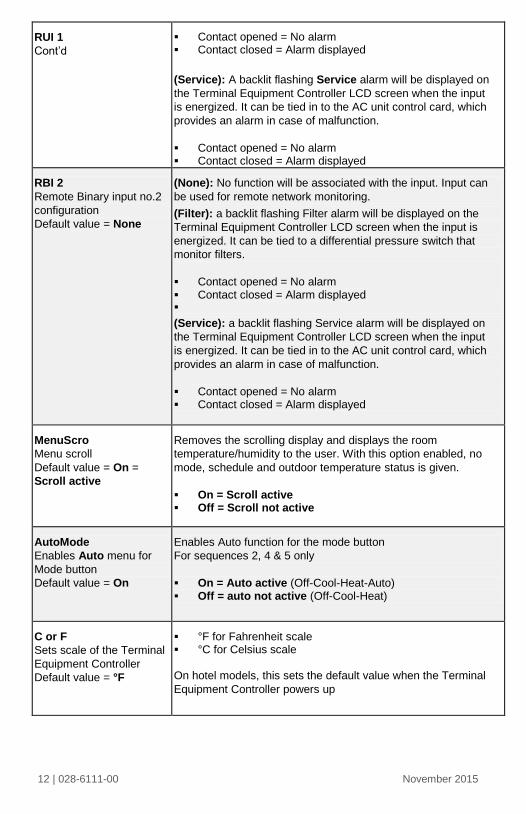
RUI 1
Cont’d
Contact opened = No alarm Contact closed = Alarm displayed
(Service): A backlit flashing Service alarm will be displayed on
the Terminal Equipment Controller LCD screen when the input
is energized. It can be tied in to the AC unit control card, which
provides an alarm in case of malfunction.
Contact opened = No alarm Contact closed = Alarm displayed
RBI 2
Remote Binary input no.2
configuration
Default value = None
(None): No function will be associated with the input. Input can
be used for remote network monitoring.
(Filter): a backlit flashing Filter alarm will be displayed on the
Terminal Equipment Controller LCD screen when the input is
energized. It can be tied to a differential pressure switch that
monitor filters.
Contact opened = No alarm Contact closed = Alarm displayed
(Service): a backlit flashing Service alarm will be displayed on
the Terminal Equipment Controller LCD screen when the input
is energized. It can be tied in to the AC unit control card, which
provides an alarm in case of malfunction.
Contact opened = No alarm Contact closed = Alarm displayed
MenuScro
Menu scroll
Default value = On =
Scroll active
Removes the scrolling display and displays the room
temperature/humidity to the user. With this option enabled, no
mode, schedule and outdoor temperature status is given.
On = Scroll active Off = Scroll not active
AutoMode
Enables Auto menu for
Mode button
Default value = On
Enables Auto function for the mode button
For sequences 2, 4 & 5 only
On = Auto active (Off-Cool-Heat-Auto) Off = auto not active (Off-Cool-Heat)
C or F
Sets scale of the Terminal
Equipment Controller
Default value = °F
°F for Fahrenheit scale °C for Celsius scale
On hotel models, this sets the default value when the Terminal
Equipment Controller powers up
13 | 028-6111-00 November 2015
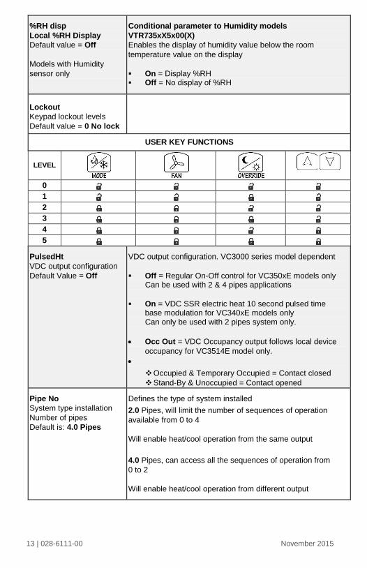
%RH disp
Local %RH Display
Default value = Off
Models with Humidity
sensor only
Conditional parameter to Humidity models
VTR735xX5x00(X)
Enables the display of humidity value below the room
temperature value on the display
On = Display %RH Off = No display of %RH
Lockout
Keypad lockout levels
Default value = 0 No lock
USER KEY FUNCTIONS
LEVEL
0 1 2 3 4 5
PulsedHt
VDC output configuration
Default Value = Off
VDC output configuration. VC3000 series model dependent
Off = Regular On-Off control for VC350xE models only Can be used with 2 & 4 pipes applications
On = VDC SSR electric heat 10 second pulsed time base modulation for VC340xE models only Can only be used with 2 pipes system only.
Occ Out = VDC Occupancy output follows local device
occupancy for VC3514E model only.
Occupied & Temporary Occupied = Contact closed
Stand-By & Unoccupied = Contact opened
Pipe No
System type installation
Number of pipes
Default is: 4.0 Pipes
Defines the type of system installed
2.0 Pipes, will limit the number of sequences of operation
available from 0 to 4
Will enable heat/cool operation from the same output
4.0 Pipes, can access all the sequences of operation from
0 to 2
Will enable heat/cool operation from different output
14 | 028-6111-00 November 2015
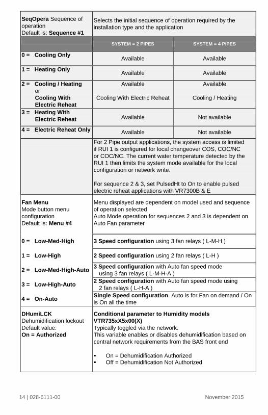
SeqOpera Sequence of
operation
Default is: Sequence #1
Selects the initial sequence of operation required by the
installation type and the application
SYSTEM = 2 PIPES SYSTEM = 4 PIPES
0 = Cooling Only Available Available
1 = Heating Only Available Available
2 = Cooling / Heating
or
Cooling With
Electric Reheat
Available
Cooling With Electric Reheat
Available
Cooling / Heating
3 = Heating With
Electric Reheat Available Not available
4 = Electric Reheat Only Available Not available
For 2 Pipe output applications, the system access is limited
if RUI 1 is configured for local changeover COS, COC/NC
or COC/NC. The current water temperature detected by the
RUI 1 then limits the system mode available for the local
configuration or network write.
For sequence 2 & 3, set PulsedHt to On to enable pulsed
electric reheat applications with VR7300B & E
Fan Menu
Mode button menu
configuration
Default is: Menu #4
Menu displayed are dependent on model used and sequence
of operation selected
Auto Mode operation for sequences 2 and 3 is dependent on
Auto Fan parameter
0 = Low-Med-High 3 Speed configuration using 3 fan relays ( L-M-H )
1 = Low-High 2 Speed configuration using 2 fan relays ( L-H )
2 = Low-Med-High-Auto 3 Speed configuration with Auto fan speed mode
using 3 fan relays ( L-M-H-A )
3 = Low-High-Auto 2 Speed configuration with Auto fan speed mode using
2 fan relays ( L-H-A )
4 = On-Auto Single Speed configuration. Auto is for Fan on demand / On
is On all the time
DHumiLCK
Dehumidification lockout
Default value:
On = Authorized
Conditional parameter to Humidity models
VTR735xX5x00(X)
Typically toggled via the network.
This variable enables or disables dehumidification based on
central network requirements from the BAS front end
On = Dehumidification Authorized Off = Dehumidification Not Authorized
15 | 028-6111-00 November 2015
%RH set
Dehumidification setpoint
Default is 50 % RH
Conditional parameter to Humidity models
VTR735xX5x00(X)
Used only if dehumidification sequence is enabled:
Range is: 30-95% RH
DehuHyst
Dehumidification
Hysterisys
Default is 5 % RH
Conditional parameter to Humidity models
VTR735xX5x00(X)
Humidity control hysterisys. Used only if dehumidification
sequence is enabled:
Range is: 2 to 20% RH
DehuCool
Maximum
Dehumidification
Cooling output
Default is 100 %
Conditional parameter to Humidity models
VTR735xX5x00(X)
Maximum cooling valve position when dehumidification is
enabled. This can be used to balance smaller reheat loads
installed relative to the capacity of the cooling coil.
Range is: 20 to 100 %
St-By TM
Stand-by Timer value
Default 0.5 hours
Time delay between the moment when the PIR sensor
detected the last movement in the area and the time when the
Terminal Equipment Controller stand-by mode and setpoints
become active.
Range is: 0.5 to 24.0 hours in 0.5hr increments
Unocc TM
Unoccupied Timer value
Default 0.0 hours
Time delay between the moment when the Terminal
Equipment Controller toggles to stand-by mode and the time
when the Terminal Equipment Controller unoccupied mode
and setpoints become active.
The factory value or 0.0 hours: Setting this parameter to its
default value of 0.0 hours disables the unoccupied timer.
This prevents the Terminal Equipment Controller to drift from
stand-by mode to unoccupied mode when PIR functions are
used
Range is: 0.0 to 24.0 hours in 0.5hr increments
St-By HT
Stand-by heating
setpoint
Default value = 69 °F
The value of this parameter should reside between the
occupied and unoccupied heating setpoints and make sure
that the difference between the stand-by and occupied value
can be recovered in a timely fashion when movement is
detected in the zone.
Stand-by heating setpoint range is: 40 to 90 °F
( 4.5 to 32.0 °C )
St-By CL
Stand-by cooling
setpoint limit
Default value = 78 °F
The value of this parameter should reside between the
occupied and unoccupied cooling setpoints and make sure
that the difference between the stand-by and occupied value
can be recovered in a timely fashion when movement is
detected in the zone.
Stand-by cooling setpoint range is: 54 to 100 °F
( 12.0 to 37.5 °C )
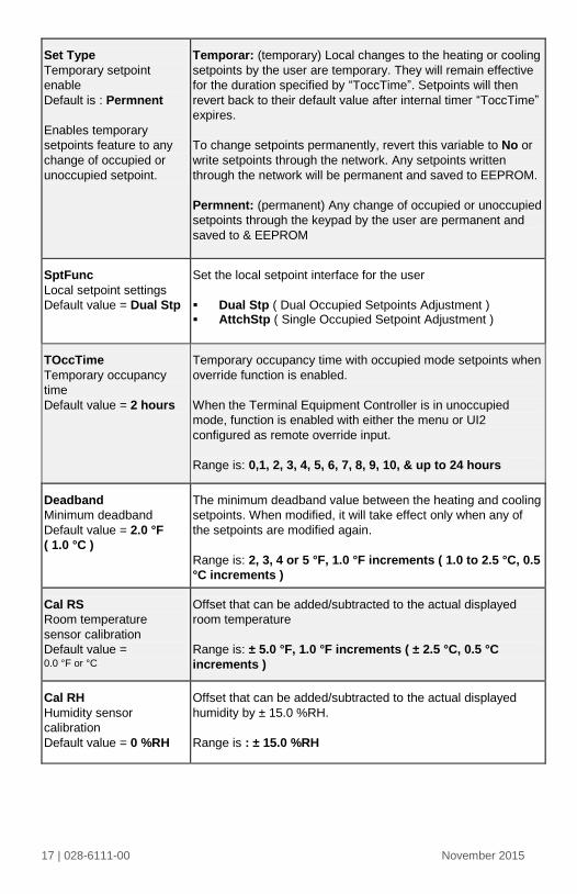
16 | 028-6111-00 November 2015
Unocc HT
Unoccupied heating
setpoint
Default value = 62 °F
Unoccupied heating setpoint range is:
40 to 90 °F ( 4.5 to 32.0 °C )
Unocc CL
Unoccupied cooling
setpoint limit
Default value = 80 °F
Unoccupied cooling setpoint range is:
54 to 100 °F ( 12.0 to 37.5 °C )
Heat max
Maximum heating
setpoint limit
Default value =
90 °F ( 32 °C )
Maximum occupied & unoccupied heating setpoint adjustment.
Heating setpoint range is: 40 to 90 °F ( 4.5 to 32.0 °C )