50
VTRAK 15110/12110/8110 QUICK START GUIDE Version 1.1 / SR5 © 2005 Promise Technology, Inc. All Rights Reserved. PROM ISE VT rak 15200
VTRAK 15110/12110/8110QUICK START GUIDE
Version 1.1 / SR5
© 2005 Promise Technology, Inc. All Rights Reserved.
PROMISE VTrak 15200
VTrak 15110/12100/8110 Quick Start Guide
Installation Task ListStep 1: Unpack the VTrak (below)
Step 2: Mount VTrak in a Rack (page 5)
Step 3: Install Disk Drives (page 5)
Step 4: Verify the SCSI HBA Card (page 8)
Step 5: Connect the SCSI Cables (page 9)
Step 6: Connect the Management Cables (page 16)
Step 7: Connect the Power (page 17)
Step 8: Set Up Management Connections (page 18)
Step 9: Install WebPAM PRO Software (page 22)
Step 10: VTrak Setup with WebPAM PRO (page 31)
Step 1: Unpack the VTrak The VTrak box contains the following items:
• VTrak Unit
• Quick Start Guide
• Null Modem Cable
• SCSI Terminators(1 for 8110; 2 for 12110 & 15110)
• Left and right mounting rails
• 1.0m External VHDCI SCSI cables (1 for 8110; 2 for 12110 & 15110)
• Screws for disk drives(36 for 8110; 52 for 12110; 64 for 15110; plus 4 spares)
• 1.5m (4.9 ft) Power cords (2)
• CD with WebPAM PRO Software, User Manual and Quick Start Guide
Warning
The electronic components within the VTrak disk array are sensitive to damage from Electro-Static Discharge (ESD). Observe appropriate precautions at all times when handling the VTrak or its subassemblies.
Important
In order to work with VTrak, the SCSI Host Bus Adapter (HBA) card you select for the Host PC must meet requirements. See page 8.
2
Step 1: Unpack the VTrak
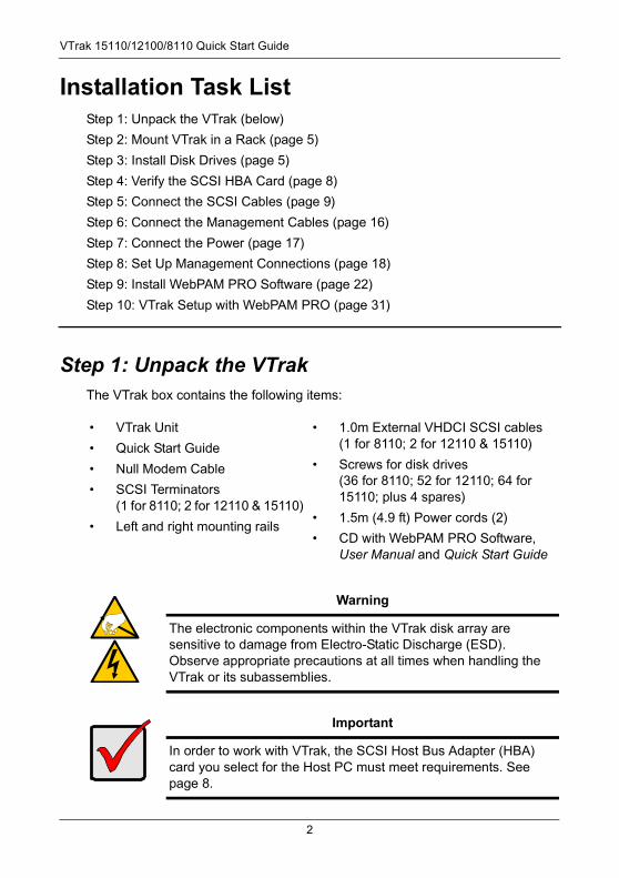
Figure 1. VTrak 15110 front view
Figure 2. VTrak 12110/8110 front view
PROMISE VTrak 15100
Power SCSI-2Activity
FRUStatus
Disk ArrayStatus
SCSI-1Activity
ControllerHeartbeat
Power
SCSI-2 Activity
FRU Status
Disk Array Status
SCSI-1 Activity
Controller Heartbeat
3
VTrak 15110/12100/8110 Quick Start Guide
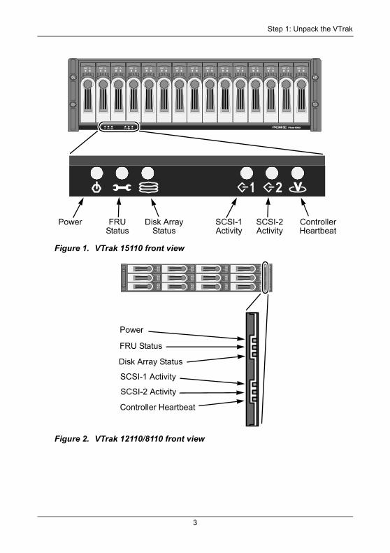
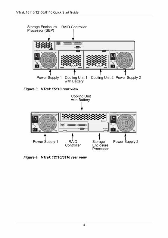
Figure 3. VTrak 15110 rear view
Figure 4. VTrak 12110/8110 rear view
Storage EnclosureProcessor (SEP)
RAID Controller
Power Supply 1 Cooling Unit 1with Battery
Power Supply 2Cooling Unit 2
Cooling Unit with Battery
Power Supply 1 RAID Controller
Power Supply 2Storage EnclosureProcessor
4
Step 2: Mount VTrak in a Rack
Step 2: Mount VTrak in a RackThe VTrak sy\ubsystem installs directly to the rack with or without using the supplied mounting rails. Refer to Chapter 2 of the VTrak User Manual for instructions on installing the rails and mounting VTrak.
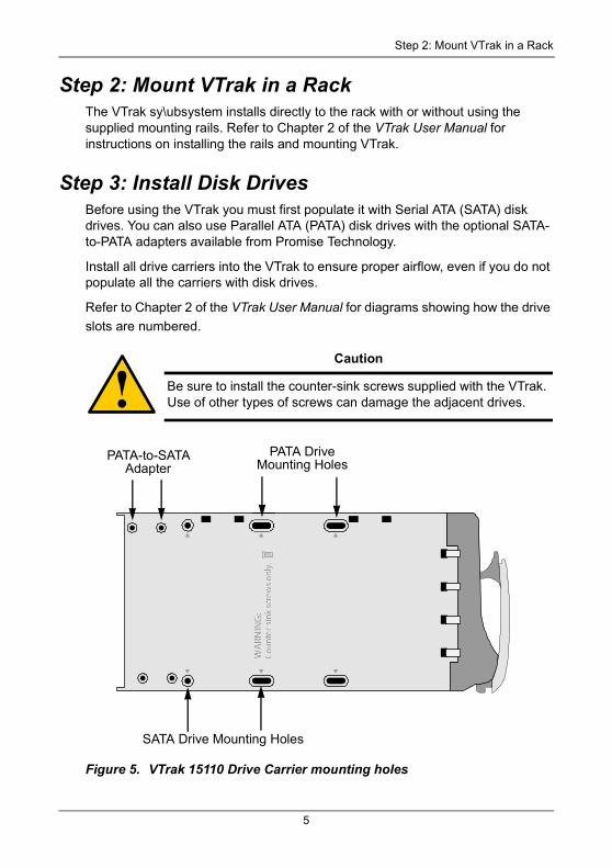
Step 3: Install Disk DrivesBefore using the VTrak you must first populate it with Serial ATA (SATA) disk drives. You can also use Parallel ATA (PATA) disk drives with the optional SATA-to-PATA adapters available from Promise Technology.
Install all drive carriers into the VTrak to ensure proper airflow, even if you do not populate all the carriers with disk drives.
Refer to Chapter 2 of the VTrak User Manual for diagrams showing how the drive
slots are numbered.
Figure 5. VTrak 15110 Drive Carrier mounting holes
Caution
Be sure to install the counter-sink screws supplied with the VTrak. Use of other types of screws can damage the adjacent drives.
PATA-to-SATA Adapter
SATA Drive Mounting Holes
PATA DriveMounting Holes
5
VTrak 15110/12100/8110 Quick Start Guide
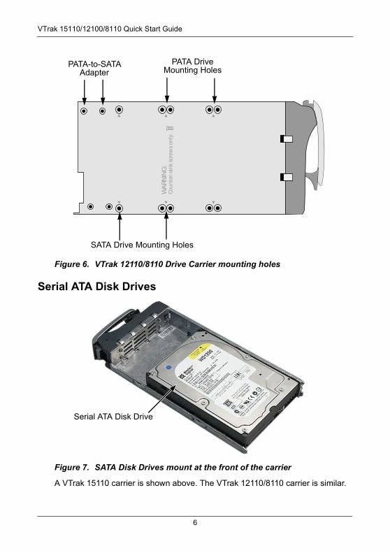
Figure 6. VTrak 12110/8110 Drive Carrier mounting holes
Serial ATA Disk Drives
Figure 7. SATA Disk Drives mount at the front of the carrier
A VTrak 15110 carrier is shown above. The VTrak 12110/8110 carrier is similar.
WA
RNIN
G:
Co
un
ter-
sin
k sc
rew
s o
nly
.
PATA-to-SATA Adapter
SATA Drive Mounting Holes
PATA DriveMounting Holes
Serial ATA Disk Drive
6
Step 3: Install Disk Drives
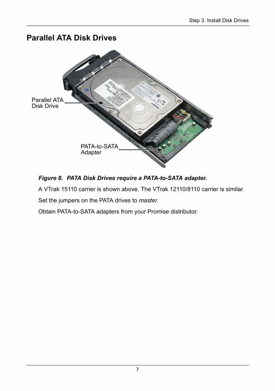
Parallel ATA Disk Drives
Figure 8. PATA Disk Drives require a PATA-to-SATA adapter.
A VTrak 15110 carrier is shown above. The VTrak 12110/8110 carrier is similar.
Set the jumpers on the PATA drives to master.
Obtain PATA-to-SATA adapters from your Promise distributor.
Parallel ATA Disk Drive
PATA-to-SATA Adapter
7
VTrak 15110/12100/8110 Quick Start Guide
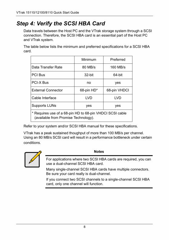
Step 4: Verify the SCSI HBA CardData travels between the Host PC and the VTrak storage system through a SCSI connection. Therefore, the SCSI HBA card is an essential part of the Host PC and VTrak system.
The table below lists the minimum and preferred specifications for a SCSI HBA card.
Refer to your system and/or SCSI HBA manual for these specifications.
VTrak has a peak sustained thoughput of more than 100 MB/s per channel. Using an 80 MB/s SCSI card will result in a performance bottleneck under certain
conditions.
Minimum Preferred
Data Transfer Rate 80 MB/s 160 MB/s
PCI Bus 32-bit 64-bit
PCI-X Bus no yes
External Connector 68-pin HD* 68-pin VHDCI
Cable Interface LVD LVD
Supports LUNs yes yes
* Requires use of a 68-pin HD to 68-pin VHDCI SCSI cable (available from Promise Technology).
Notes
For applications where two SCSI HBA cards are required, you can use a dual-channel SCSI HBA card.
Many single-channel SCSI HBA cards have multiple connectors. Be sure your card really is dual-channel.
If you connect two SCSI channels to a single-channel SCSI HBA card, only one channel will function.
8
Step 5: Connect the SCSI Cables
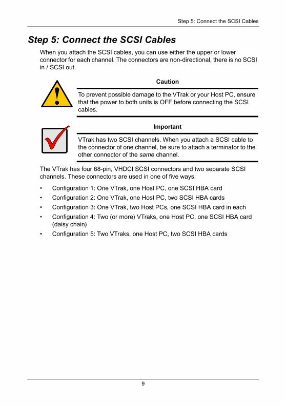
Step 5: Connect the SCSI Cables When you attach the SCSI cables, you can use either the upper or lower connector for each channel. The connectors are non-directional, there is no SCSI in / SCSI out.
The VTrak has four 68-pin, VHDCI SCSI connectors and two separate SCSI channels. These connectors are used in one of five ways:
• Configuration 1: One VTrak, one Host PC, one SCSI HBA card
• Configuration 2: One VTrak, one Host PC, two SCSI HBA cards
• Configuration 3: One VTrak, two Host PCs, one SCSI HBA card in each
• Configuration 4: Two (or more) VTraks, one Host PC, one SCSI HBA card (daisy chain)
• Configuration 5: Two VTraks, one Host PC, two SCSI HBA cards
Caution
To prevent possible damage to the VTrak or your Host PC, ensure that the power to both units is OFF before connecting the SCSI cables.
Important
VTrak has two SCSI channels. When you attach a SCSI cable to the connector of one channel, be sure to attach a terminator to the other connector of the same channel.
9
VTrak 15110/12100/8110 Quick Start Guide
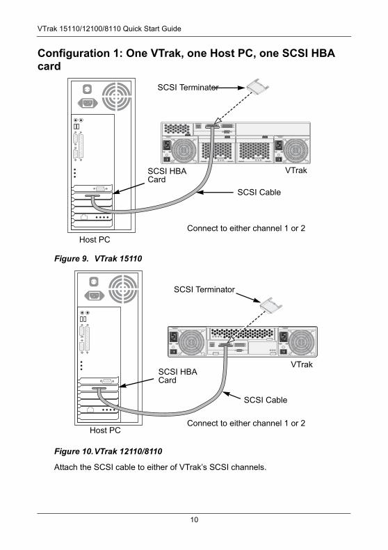
Configuration 1: One VTrak, one Host PC, one SCSI HBA card
Figure 9. VTrak 15110
Figure 10.VTrak 12110/8110
Attach the SCSI cable to either of VTrak’s SCSI channels.
SCSI Terminator
SCSI Cable
SCSI HBA Card
Host PC
VTrak
Connect to either channel 1 or 2
SCSI Terminator
SCSI Cable
SCSI HBA Card
Host PC
VTrak
Connect to either channel 1 or 2
10
Step 5: Connect the SCSI Cables
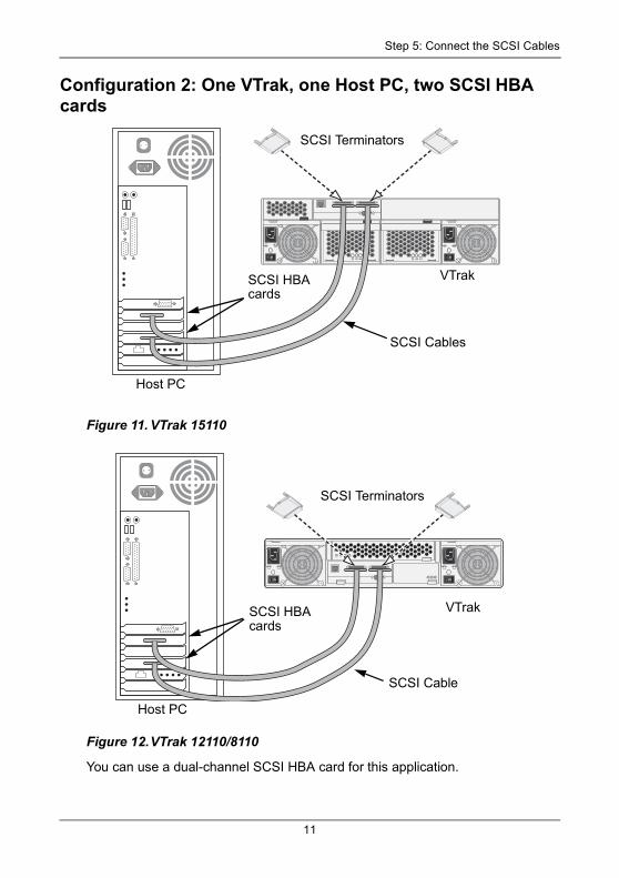
Configuration 2: One VTrak, one Host PC, two SCSI HBA cards
Figure 11. VTrak 15110
Figure 12.VTrak 12110/8110
You can use a dual-channel SCSI HBA card for this application.
Host PC
VTrakSCSI HBA cards
SCSI Cables
SCSI Terminators
Host PC
VTrakSCSI HBA cards
SCSI Terminators
SCSI Cable
11
VTrak 15110/12100/8110 Quick Start Guide
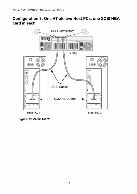
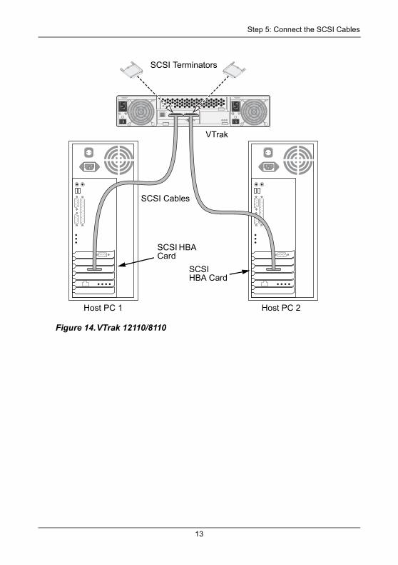
Configuration 3: One VTrak, two Host PCs, one SCSI HBA card in each
Figure 13.VTrak 15110
Host PC 1 Host PC 2
SCSI HBA Cards
SCSI Cables
SCSI Terminators
VTrak
12
Step 5: Connect the SCSI Cables
Figure 14.VTrak 12110/8110
Host PC 1 Host PC 2
SCSI HBA Card
SCSI HBA Card
SCSI Cables
SCSI Terminators
VTrak
13
VTrak 15110/12100/8110 Quick Start Guide
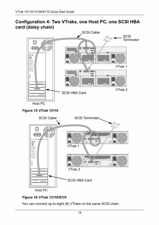
Configuration 4: Two VTraks, one Host PC, one SCSI HBA card (daisy chain)
Figure 15.VTrak 15110
Figure 16.VTrak 12110/8110
You can connect up to eight (8) VTraks on the same SCSI chain.
Host PC
SCSI CableSCSITerminator
VTrak 1
VTrak 2SCSI HBA Card
Host PC
SCSI Cable SCSI Terminator
VTrak 1
VTrak 2
SCSI HBA Card
14
Step 5: Connect the SCSI Cables
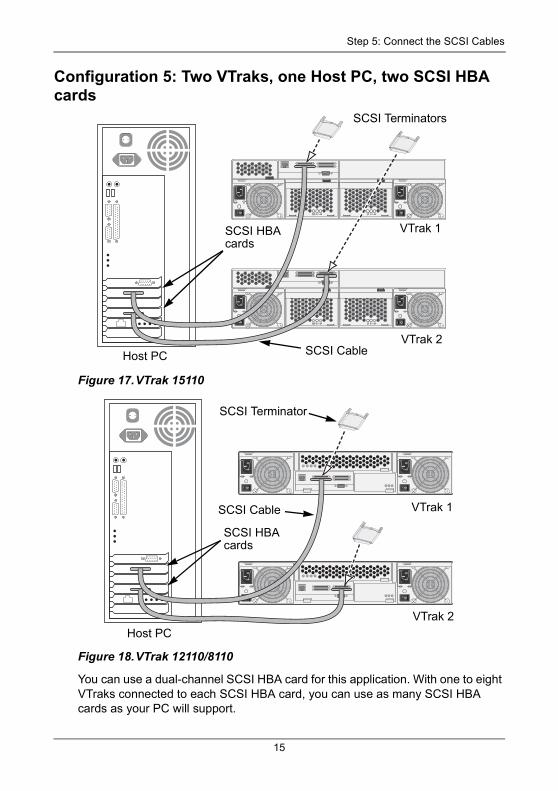
Configuration 5: Two VTraks, one Host PC, two SCSI HBA cards
Figure 17.VTrak 15110
Figure 18.VTrak 12110/8110
You can use a dual-channel SCSI HBA card for this application. With one to eight VTraks connected to each SCSI HBA card, you can use as many SCSI HBA cards as your PC will support.
Host PC
VTrak 1SCSI HBA cards
SCSI Terminators
VTrak 2SCSI Cable
Host PC
VTrak 1
SCSI HBA cards
SCSI Terminator
VTrak 2
SCSI Cable
15
VTrak 15110/12100/8110 Quick Start Guide
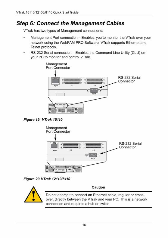
Step 6: Connect the Management CablesVTrak has two types of Management connections:
• Management Port connection – Enables you to monitor the VTrak over your network using the WebPAM PRO Software. VTrak supports Ethernet and Telnet protocols.
• RS-232 Serial connection – Enables the Command Line Utility (CLU) on your PC to monitor and control VTrak.
Figure 19. VTrak 15110
Figure 20.VTrak 12110/8110
Caution
Do not attempt to connect an Ethernet cable, regular or cross-over, directly between the VTrak and your PC. This is a network connection and requires a hub or switch.
Mgmt
IOIOI
Management Port Connector
RS-232 Serial Connector
Mgmt
IOIOI
Management Port Connector
RS-232 Serial Connector
16
Step 7: Connect the Power
Macintosh UsersIf your Host PC is an Apple Macintosh, you do not have the RS-232 serial port needed to set-up a Management connection.
Obtain the following items to make a serial connection:
• A USB to DB-9 serial converter
• Terminal emulation software
Several manufacturers offer USB to DB-9 serial converters and cables. For terminal emulation software, go to:
http://homepage.mac.com/dalverson/zterm/ Download and install the ZTerm software onto your system.
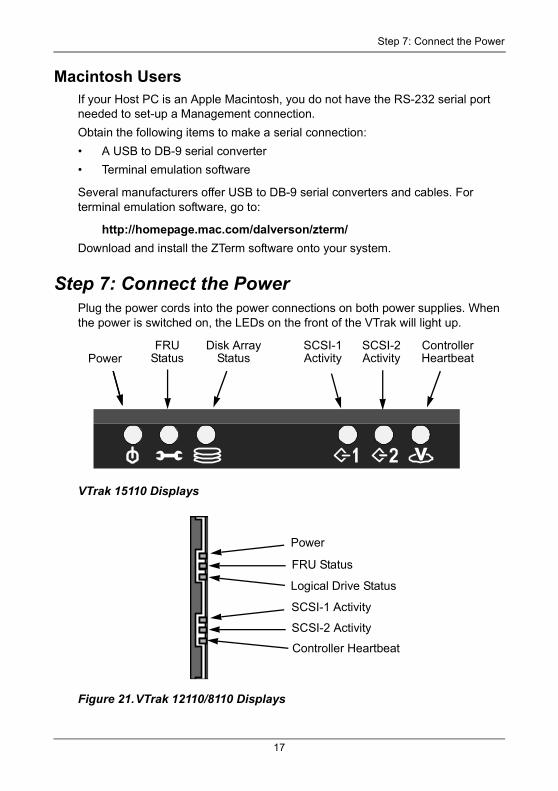
Step 7: Connect the PowerPlug the power cords into the power connections on both power supplies. When the power is switched on, the LEDs on the front of the VTrak will light up.
VTrak 15110 Displays
Figure 21.VTrak 12110/8110 Displays
PowerSCSI-2Activity
FRUStatus
Disk ArrayStatus
SCSI-1Activity
ControllerHeartbeat
Power
SCSI-2 Activity
FRU Status
Logical Drive Status
SCSI-1 Activity
Controller Heartbeat
17
VTrak 15110/12100/8110 Quick Start Guide
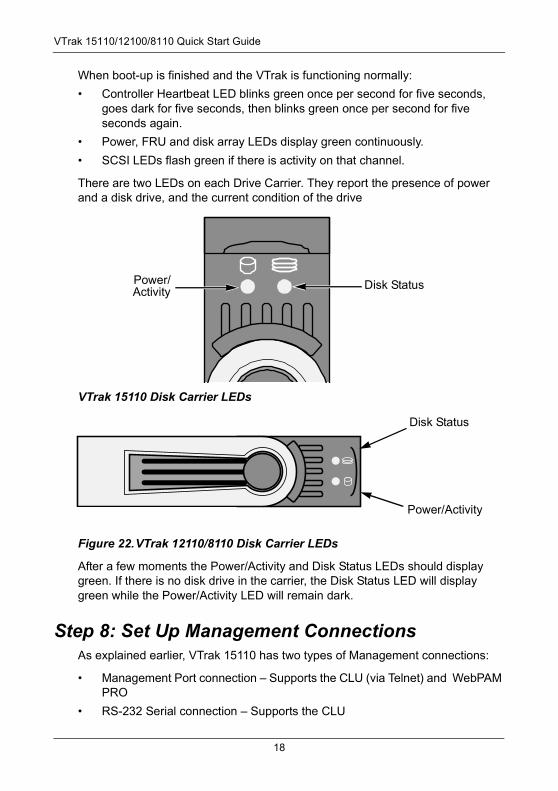
When boot-up is finished and the VTrak is functioning normally:
• Controller Heartbeat LED blinks green once per second for five seconds, goes dark for five seconds, then blinks green once per second for five seconds again.
• Power, FRU and disk array LEDs display green continuously.
• SCSI LEDs flash green if there is activity on that channel.
There are two LEDs on each Drive Carrier. They report the presence of power and a disk drive, and the current condition of the drive
VTrak 15110 Disk Carrier LEDs
Figure 22.VTrak 12110/8110 Disk Carrier LEDs
After a few moments the Power/Activity and Disk Status LEDs should display green. If there is no disk drive in the carrier, the Disk Status LED will display green while the Power/Activity LED will remain dark.
Step 8: Set Up Management ConnectionsAs explained earlier, VTrak 15110 has two types of Management connections:
• Management Port connection – Supports the CLU (via Telnet) and WebPAM PRO
• RS-232 Serial connection – Supports the CLU
Disk StatusPower/Activity
Disk Status
Power/Activity
18
Step 8: Set Up Management Connections
The physical (cable) connections for these are described in an earlier section. If you have not made these connections, do so before continuing.
Use the following procedures to enable Management connections for VTrak. Terminal Emulation is required in all cases. The others are required depending on the Management connections you choose.
Terminal EmulationTerminal emulation is the means of communication over an RS-232 serial connection. In the following procedure, you will establish a Terminal Emulation link between the Host PC and the VTrak.
Regardless of your choice of management connection, you must first establish a Terminal Emulation connection, such as HyperTerminal, for example.
1. Change your PC’s COM Port settings to agree with the following:
• Bits per second: 115200
• Data bits: 8
• Parity: None
• Stop bits: 1
• Flow control: none
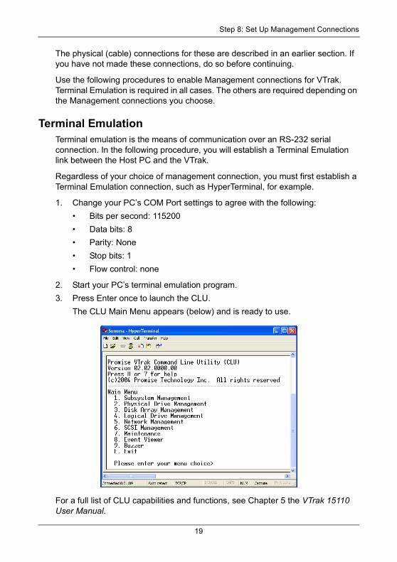
2. Start your PC’s terminal emulation program.
3. Press Enter once to launch the CLU.
The CLU Main Menu appears (below) and is ready to use.
For a full list of CLU capabilities and functions, see Chapter 5 the VTrak 15110 User Manual.
19
VTrak 15110/12100/8110 Quick Start Guide
Set IP Addresses and Subnet MaskThis procedure is required for a network connection to the VTrak. In order for the network connection to work, you must set the IP addresses of the Management Port and Gateway, and set the Subnet Mask. You can enable DHCP or make the settings manually.
If you do not plan to use a network connection, you can skip to the next
procedure.
To enable DHCP:
1. From the Main Menu, press 5 and Enter to access Network Management.
2. From the Network Management menu, press 1 and Enter to access the Management Port menu.
3. Press 1 and Enter to access DHCP.
4. Press Y and Enter to enable DHCP on VTrak.
5. Press Enter again to return to the Management Port menu.
To make settings manually:
1. From the Main Menu, press 5 and Enter to access Network Management.
2. From the Network Management menu, press 1 and Enter to access the Management Port menu.
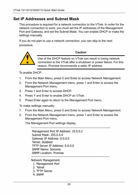
The Management Port settings display.
-------------------------------------------------------------------------- Management Port IP Address: 10.0.0.2 Subnet Mask: 255.0.0.0 Gateway IP Address: 0.0.0.0 Telnet: disabled TFTP Server IP Address: 0.0.0.0 SNMP Name: Sonoma SNMP Location: Promise-------------------------------------------------------------------------Network Management 1. Management Port 2. Telnet 3. TFTP Server 4. SNMP
Caution
Use of the DHCP feature on VTrak can result in losing network connection to the VTrak after a shutdown or power failure. For this reason, Promise recommends a static IP address.
20
Step 8: Set Up Management Connections
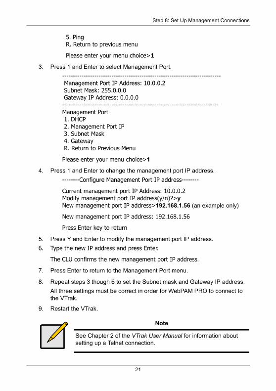
5. Ping R. Return to previous menu
Please enter your menu choice>1
3. Press 1 and Enter to select Management Port.
-------------------------------------------------------------------------- Management Port IP Address: 10.0.0.2 Subnet Mask: 255.0.0.0 Gateway IP Address: 0.0.0.0-------------------------------------------------------------------------Management Port 1. DHCP 2. Management Port IP 3. Subnet Mask 4. Gateway R. Return to Previous Menu
Please enter your menu choice>1
4. Press 1 and Enter to change the management port IP address.
--------Configure Management Port IP address--------
Current management port IP Address: 10.0.0.2Modify management port IP address(y/n)?>yNew management port IP address>192.168.1.56 (an example only)
New management port IP address: 192.168.1.56
Press Enter key to return
5. Press Y and Enter to modify the management port IP address.
6. Type the new IP address and press Enter.
The CLU confirms the new management port IP address.
7. Press Enter to return to the Management Port menu.
8. Repeat steps 3 though 6 to set the Subnet mask and Gateway IP address.
All three settings must be correct in order for WebPAM PRO to connect to the VTrak.
9. Restart the VTrak.
Note
See Chapter 2 of the VTrak User Manual for information about setting up a Telnet connection.
21
VTrak 15110/12100/8110 Quick Start Guide
Step 9: Install WebPAM PRO SoftwareWeb-Based Promise Array Management—Professional (WebPAM PRO) software provides a browser-based graphic user interface used to monitor and manage VTrak and its disk arrays. Because it works over your network, it can monitor and control multiple VTraks. WebPAM PRO consists of two components:
• Utility Server – WebPAM PRO software you install
• CIMOM Agent – WebPAM PRO component preinstalled on the VTrak
Utility Server Installation LocationsWhen you install WebPAM PRO, you are installing the Utility Server. Where you install WebPAM PRO depends on your management connection. If you plan to use the VTrak Management (network) port, there are three possible locations.
• A networked PC
• A network file server
• The Host PC
Installation GuidelinesWhen you install WebPAM PRO on a network, follow these rules.
• Install the Utility Server only on a PC or Server that is permanently connected to your network.
• Install only one instance of the Utility Server on your network.
Operating System SupportOn the PC or server where you install WebPAM PRO, Promise Technology recommends:
• Windows 2000
• Windows XP Professional
• Windows 2003
• RedHat Linux
• SuSE Linux
• Mac OS X
• Solaris 9
The Utility Server supports these operating systems. Choose one of them to take full advantage of all the features of WebPAM PRO.
22
Step 9: Install WebPAM PRO Software
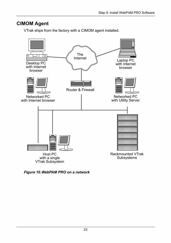
CIMOM AgentVTrak ships from the factory with a CIMOM agent installed.
Figure 10.WebPAM PRO on a network
Desktop PCwith Internet
browser
Laptop PCwith Internet
browser
TheInternet
Networked PCwith Internet browser
Networked PC with Utility Server
Router & Firewall
Rackmounted VTrak Subsystems
Host PCwith a single
VTrak Subsystem
23
VTrak 15110/12100/8110 Quick Start Guide
Internet BrowserTypically an Internet browser comes with your operating system. WebPAM PRO does not include a browser. For computers that will remotely monitor and manage the RAID, the Internet Browser is the only software required.
Your Internet Browser provides the means for you to monitor and configure your Promise RAID products using WebPAM PRO. You can use the most recent versions of either Internet Explorer or Netscape Navigator.
Before you start…1. Obtain the IP addresses of these devices:
• The PC or server where you plan to install WebPAM PRO
• The VTrak(s) you plan to monitor
2. If you are planning to use other applications that rely on JRE or JDK, always install them first before you install WebPAM PRO. WebPAM PRO will use the existing JRE rather than installing a second one.
WebPAM PRO will install JRE 1.4 on your system unless you already have JRE or JDK versions 1.3.0 or 1.4.
Install WebPAM PROWindowsFollow these steps to install WebPAM PRO on your Windows-based PC or Server.
1. Boot the PC/server and launch Windows.
If the computer is already running, exit all programs.
2. Insert the software CD into your CD-ROM drive.
3. Double-click on the Install CD's icon to open it.
4. Double-click on the Installer icon to launch it (right).
The first WebPAM PRO installation dialog box appears, as shown on page 26.
LinuxFollow these steps to install WebPAM PRO on your Linux-based PC or Server.
1. Boot the PC/server and launch the Linux GUI.
If the computer is already running, exit all programs.
24
Step 9: Install WebPAM PRO Software
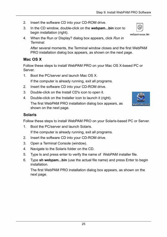
2. Insert the software CD into your CD-ROM drive.
3. In the CD window, double-click on the webpam...bin icon to begin installation (right).
4. When the Run or Display? dialog box appears, click Run in Terminal.After several moments, the Terminal window closes and the first WebPAM PRO installation dialog box appears, as shown on the next page.
Mac OS XFollow these steps to install WebPAM PRO on your Mac OS X-based PC or Server.
1. Boot the PC/server and launch Mac OS X.
If the computer is already running, exit all programs.
2. Insert the software CD into your CD-ROM drive.
3. Double-click on the Install CD's icon to open it.
4. Double-click on the Installer icon to launch it (right).
The first WebPAM PRO installation dialog box appears, as shown on the next page.
SolarisFollow these steps to install WebPAM PRO on your Solaris-based PC or Server.
1. Boot the PC/server and launch Solaris.
If the computer is already running, exit all programs.
2. Insert the software CD into your CD-ROM drive.
3. Open a Terminal Console (window).
4. Navigate to the Solaris folder on the CD.
5. Type ls and press enter to verify the name of WebPAM installer file.
6. Type sh webpam...bin (use the actual file name) and press Enter to begin installation.
The first WebPAM PRO installation dialog box appears, as shown on the next page.
25
VTrak 15110/12100/8110 Quick Start Guide
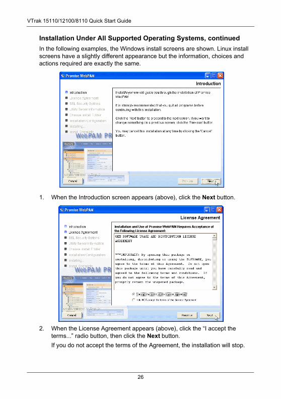
Installation Under All Supported Operating Systems, continuedIn the following examples, the Windows install screens are shown. Linux install screens have a slightly different appearance but the information, choices and actions required are exactly the same.
1. When the Introduction screen appears (above), click the Next button.
2. When the License Agreement appears (above), click the “I accept the terms...” radio button, then click the Next button.
If you do not accept the terms of the Agreement, the installation will stop.
26
Step 9: Install WebPAM PRO Software
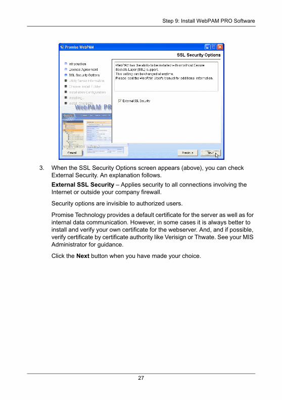
3. When the SSL Security Options screen appears (above), you can check External Security. An explanation follows.
External SSL Security – Applies security to all connections involving the Internet or outside your company firewall.
Security options are invisible to authorized users.
Promise Technology provides a default certificate for the server as well as for internal data communication. However, in some cases it is always better to install and verify your own certificate for the webserver. And, and if possible, verify certificate by certificate authority like Verisign or Thwate. See your MIS Administrator for guidance.
Click the Next button when you have made your choice.
27
VTrak 15110/12100/8110 Quick Start Guide
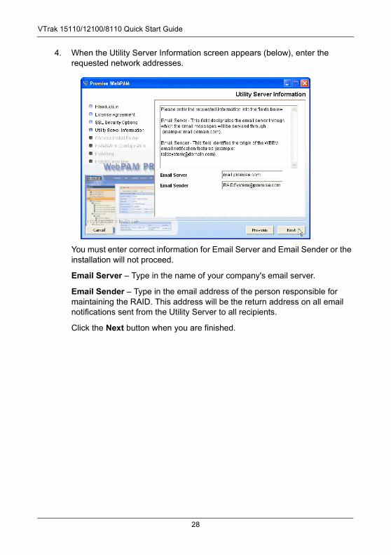
4. When the Utility Server Information screen appears (below), enter the requested network addresses.
You must enter correct information for Email Server and Email Sender or the installation will not proceed.
Email Server – Type in the name of your company's email server.
Email Sender – Type in the email address of the person responsible for maintaining the RAID. This address will be the return address on all email notifications sent from the Utility Server to all recipients.
Click the Next button when you are finished.
28
Step 9: Install WebPAM PRO Software
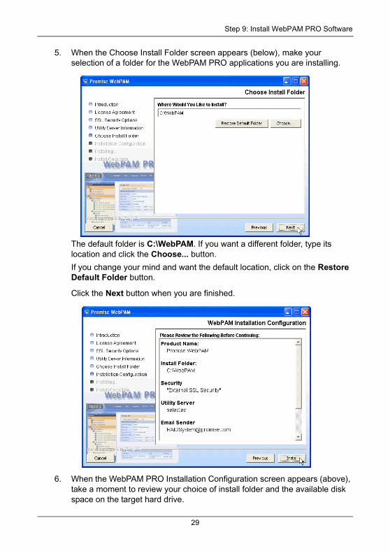
5. When the Choose Install Folder screen appears (below), make your selection of a folder for the WebPAM PRO applications you are installing.
The default folder is C:\WebPAM. If you want a different folder, type its location and click the Choose... button.
If you change your mind and want the default location, click on the Restore Default Folder button.
Click the Next button when you are finished.
6. When the WebPAM PRO Installation Configuration screen appears (above), take a moment to review your choice of install folder and the available disk space on the target hard drive.
29
VTrak 15110/12100/8110 Quick Start Guide
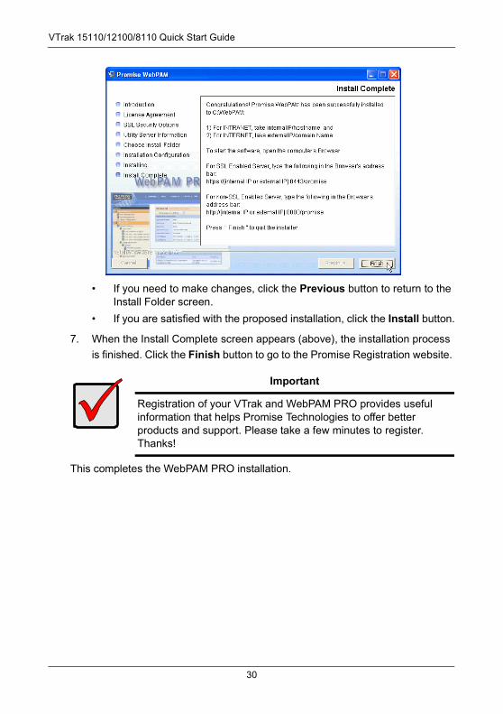
• If you need to make changes, click the Previous button to return to the Install Folder screen.
• If you are satisfied with the proposed installation, click the Install button.
7. When the Install Complete screen appears (above), the installation process
is finished. Click the Finish button to go to the Promise Registration website.
This completes the WebPAM PRO installation.
Important
Registration of your VTrak and WebPAM PRO provides useful information that helps Promise Technologies to offer better products and support. Please take a few minutes to register. Thanks!
30
Step 10: VTrak Setup with WebPAM PRO
Step 10: VTrak Setup with WebPAM PROSet up with WebPAM PRO consists of the following steps:
1. Log-in to WebPAM PRO (below)
2. Add a Subsystem (VTrak) (page 34)
3. Access a Subsystem (VTrak) (page 34)
4. Create a Disk Array (page 36)
5. Create a Logical Drive (page 42)
6. Assign a SCSI Target ID (page 42)
7. Log-out of WebPAM PRO (page 44)
8. Internet Connection using WebPAM PRO (page 44)
Log-in to WebPAM PRO1. Launch your Browser.
2. In the Browser address field, type in the IP address of the PC/Server where you installed WebPAM PRO, as explained below. Do not type the VTrak’s IP address.
If you did not choose the External Security option during WebPAM PRO installation, use the Regular connection.
If you chose the External Security option during WebPAM PRO installation, use the Secure connection.
Regular Connection• WebPAM PRO uses an HTTP connection. . . . . . . . . . . . . . . . .http://
• Enter the PC/Server’s IP address . . . . . . . . . . . . . . . 192.168.10.46(Where you installed WebPAM)
• Enter the Port number . . . . . . . . . . . . . . . . . . . . . . . . . . . . . . . :8080
• Add to launch WebPAM PRO . . . . . . . . . . . . . . . . . . . . . . . /promise
Together, your entry looks like this:
http://192.168.10.46:8080/promise
Secure Connection• WebPAM PRO uses a secure HTTP connection . . . . . . . . . . .https://
• Enter the PC/Server’s IP address . . . . . . . . . . . . . . . 192.168.10.46(Where you installed WebPAM)
• Enter the Port number . . . . . . . . . . . . . . . . . . . . . . . . . . . . . . . :8443
• Add to launch WebPAM PRO . . . . . . . . . . . . . . . . . . . . . . . /promise
Together, your entry looks like this:
31
VTrak 15110/12100/8110 Quick Start Guide
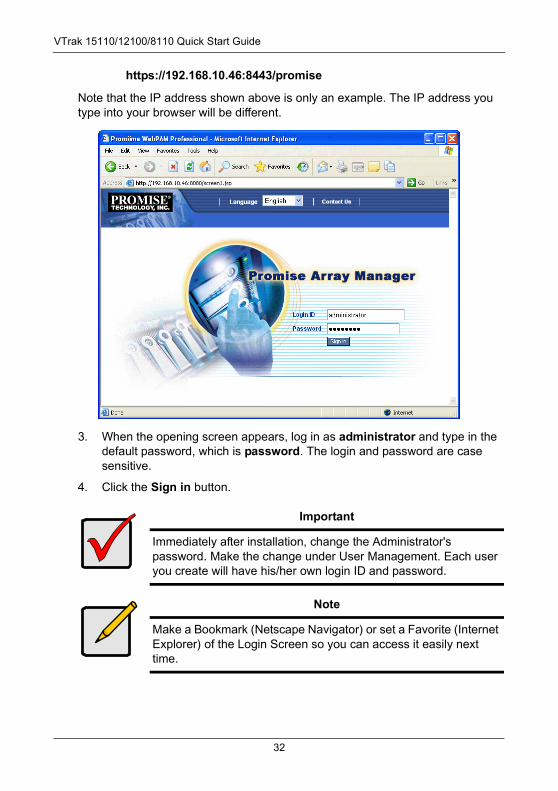
https://192.168.10.46:8443/promise
Note that the IP address shown above is only an example. The IP address you type into your browser will be different.
3. When the opening screen appears, log in as administrator and type in the default password, which is password. The login and password are case sensitive.
4. Click the Sign in button.
Important
Immediately after installation, change the Administrator's password. Make the change under User Management. Each user you create will have his/her own login ID and password.
Note
Make a Bookmark (Netscape Navigator) or set a Favorite (Internet Explorer) of the Login Screen so you can access it easily next time.
32
Step 10: VTrak Setup with WebPAM PRO
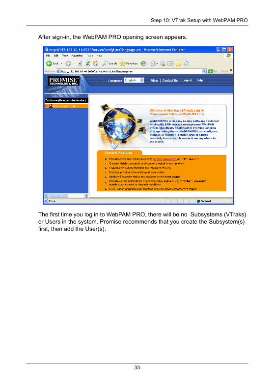
After sign-in, the WebPAM PRO opening screen appears.
The first time you log in to WebPAM PRO, there will be no Subsystems (VTraks) or Users in the system. Promise recommends that you create the Subsystem(s) first, then add the User(s).
33
VTrak 15110/12100/8110 Quick Start Guide
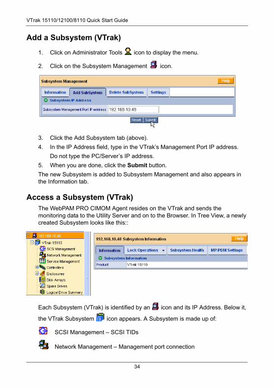
Add a Subsystem (VTrak)
1. Click on Administrator Tools icon to display the menu.
2. Click on the Subsystem Management icon.
3. Click the Add Subsystem tab (above).
4. In the IP Address field, type in the VTrak’s Management Port IP address.
Do not type the PC/Server’s IP address.
5. When you are done, click the Submit button.
The new Subsystem is added to Subsystem Management and also appears in the Information tab.
Access a Subsystem (VTrak)The WebPAM PRO CIMOM Agent resides on the VTrak and sends the monitoring data to the Utility Server and on to the Browser. In Tree View, a newly created Subsystem looks like this::
Each Subsystem (VTrak) is identified by an icon and its IP Address. Below it,
the VTrak Subsystem icon appears. A Subsystem is made up of:
SCSI Management – SCSI TIDs
Network Management – Management port connection
34
Step 10: VTrak Setup with WebPAM PRO
Service Management – SNMP, Telnet and CIM services
Controllers – RAID Management on VTrak
Enclosures – Power supplies, cooling, cache battery, circuit cards
Disk Arrays – Creation and management of disk arrays and logical drives
Spare Drives – Physical drives assigned as global or dedicated hot spares
Logical Drive Summary – A list of all logical drives in this enclosure, regardless of the disk array to which they belong
If you do not see these details in the Tree View, it means your network connection to VTrak is not working. Restore your connection before proceeding.
If you do not see anything, lower your browser’s security settings.
35
VTrak 15110/12100/8110 Quick Start Guide
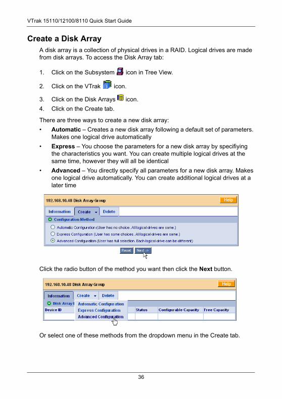
Create a Disk ArrayA disk array is a collection of physical drives in a RAID. Logical drives are made from disk arrays. To access the Disk Array tab:
1. Click on the Subsystem icon in Tree View.
2. Click on the VTrak icon.
3. Click on the Disk Arrays icon.
4. Click on the Create tab.
There are three ways to create a new disk array:
• Automatic – Creates a new disk array following a default set of parameters. Makes one logical drive automatically
• Express – You choose the parameters for a new disk array by specifiying the characteristics you want. You can create multiple logical drives at the same time, however they will all be identical
• Advanced – You directly specify all parameters for a new disk array. Makes one logical drive automatically. You can create additional logical drives at a later time
Click the radio button of the method you want then click the Next button.
Or select one of these methods from the dropdown menu in the Create tab.
36
Step 10: VTrak Setup with WebPAM PRO
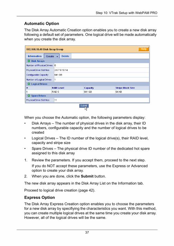
Automatic OptionThe Disk Array Automatic Creation option enables you to create a new disk array following a default set of parameters. One logical drive will be made automatically when you create the disk array.
When you choose the Automatic option, the following parameters display:
• Disk Arrays – The number of physical drives in the disk array, their ID numbers, configurable capacity and the number of logical drives to be created
• Logical Drives – The ID number of the logical drive(s), their RAID level, capacity and stripe size
• Spare Drives – The physical drive ID number of the dedicated hot spare assigned to this disk array
1. Review the parameters. If you accept them, proceed to the next step.
If you do NOT accept these parameters, use the Express or Advanced option to create your disk array.
2. When you are done, click the Submit button.
The new disk array appears in the Disk Array List on the Information tab.
Proceed to logical drive creation (page 42).
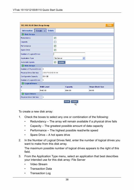
Express OptionThe Disk Array Express Creation option enables you to choose the parameters for a new disk array by specifiying the characteristics you want. With this method, you can create multiple logical drives at the same time you create your disk array. However, all of the logical drives will be the same.
37
VTrak 15110/12100/8110 Quick Start Guide
To create a new disk array:
1. Check the boxes to select any one or combination of the following:
• Redundancy – The array will remain available if a physical drive fails
• Capacity – The greatest possible amount of data capacity
• Performance – The highest possible read/write speed
• Spare Drive – A hot spare drive
2. In the Number of Logical Drives field, enter the number of logical drives you want to make from this disk array.
The maximum possible number of logical drives appears to the right of this field.
3. From the Application Type menu, select an application that best describes your intended use for this disk array: File Server
• Video Stream
• Transaction Data
• Transaction Log
38
Step 10: VTrak Setup with WebPAM PRO
• Other
4. Click the Update button.
Or check the Automatic Update box and updates will occur automatically.
The following parameters display:
• Disk Arrays – The number of physical drives in the disk array, their ID numbers, configurable capacity and the number of logical drives to be created
• Logical Drives – The ID number of the logical drive(s), their RAID level, capacity and stripe size
• Spare Drives – The physical drive ID number of the dedicated hot spare assigned to this disk array
5. If you accept these parameters, proceed to the next step.
If you do NOT accept these parameters, review and modify your selections in the previous steps.
6. When you are done, click the Submit button.
The new disk array appears in the Disk Array List on the Information tab.
Proceed to logical drive creation (page 42).
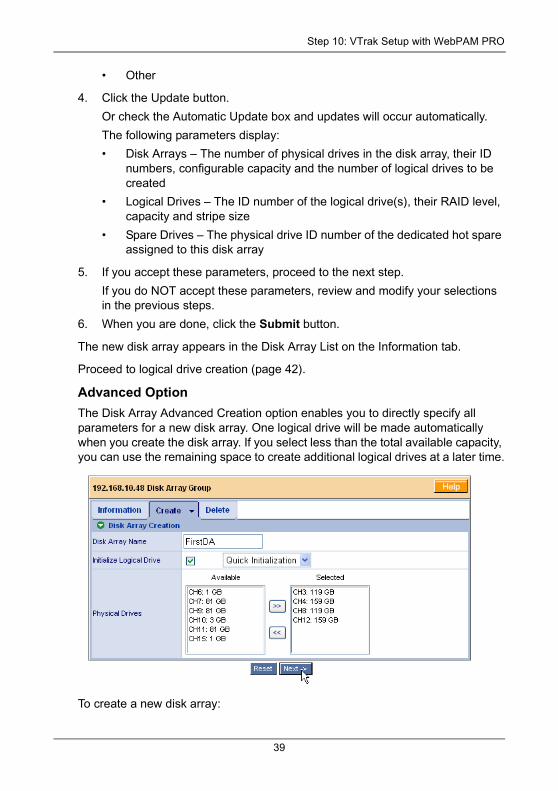
Advanced OptionThe Disk Array Advanced Creation option enables you to directly specify all parameters for a new disk array. One logical drive will be made automatically when you create the disk array. If you select less than the total available capacity, you can use the remaining space to create additional logical drives at a later time.
To create a new disk array:
39
VTrak 15110/12100/8110 Quick Start Guide
1. Enter a name for the disk array in the field provided.
2. Check the box to enable initialization, if desired.
If you checked the initialization box, select the type of initialization from the dropdown menu.
• Quick – Erases the reserve sectors of the physical drives being added to the disk array.
• Full – Erases all sectors of the physical drives being added to the disk array.
3. Highlight physical drives you want in the disk array from the Available list and press the >> button to move them to the Selected list.
You can also double-click them to move them.
4. When you are done, click the Next button.
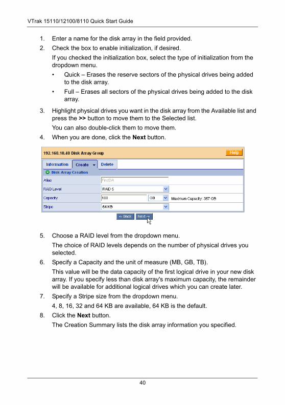
5. Choose a RAID level from the dropdown menu.
The choice of RAID levels depends on the number of physical drives you selected.
6. Specify a Capacity and the unit of measure (MB, GB, TB).
This value will be the data capacity of the first logical drive in your new disk array. If you specify less than disk array's maximum capacity, the remainder will be available for additional logical drives which you can create later.
7. Specify a Stripe size from the dropdown menu.
4, 8, 16, 32 and 64 KB are available, 64 KB is the default.
8. Click the Next button.
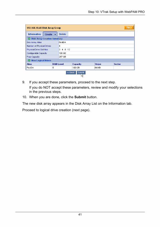
The Creation Summary lists the disk array information you specified.
40
Step 10: VTrak Setup with WebPAM PRO
9. If you accept these parameters, proceed to the next step.
If you do NOT accept these parameters, review and modify your selections in the previous steps.
10. When you are done, click the Submit button.
The new disk array appears in the Disk Array List on the Information tab.
Proceed to logical drive creation (next page).
41
VTrak 15110/12100/8110 Quick Start Guide
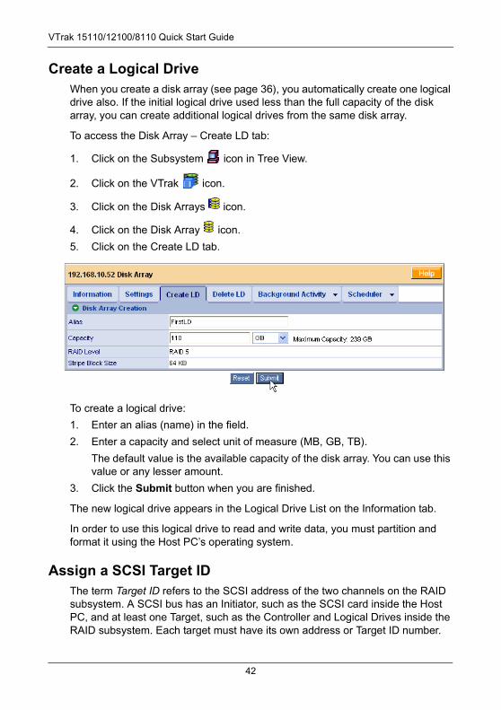
Create a Logical DriveWhen you create a disk array (see page 36), you automatically create one logical drive also. If the initial logical drive used less than the full capacity of the disk array, you can create additional logical drives from the same disk array.
To access the Disk Array – Create LD tab:
1. Click on the Subsystem icon in Tree View.
2. Click on the VTrak icon.
3. Click on the Disk Arrays icon.
4. Click on the Disk Array icon.
5. Click on the Create LD tab.
To create a logical drive:
1. Enter an alias (name) in the field.
2. Enter a capacity and select unit of measure (MB, GB, TB).
The default value is the available capacity of the disk array. You can use this value or any lesser amount.
3. Click the Submit button when you are finished.
The new logical drive appears in the Logical Drive List on the Information tab.
In order to use this logical drive to read and write data, you must partition and format it using the Host PC’s operating system.
Assign a SCSI Target IDThe term Target ID refers to the SCSI address of the two channels on the RAID subsystem. A SCSI bus has an Initiator, such as the SCSI card inside the Host PC, and at least one Target, such as the Controller and Logical Drives inside the RAID subsystem. Each target must have its own address or Target ID number.
42
Step 10: VTrak Setup with WebPAM PRO
Target IDs can be divided into Logical Unit Numbers (LUNs) to extend the number of available addresses. The default TID settings for both SCSI channels is 0. This setting is adequate for most WebPAM and RAID subsystem configurations. If an address conflict occurs, you might have to change the TID setting.
You must have Creation Rights to access this function.
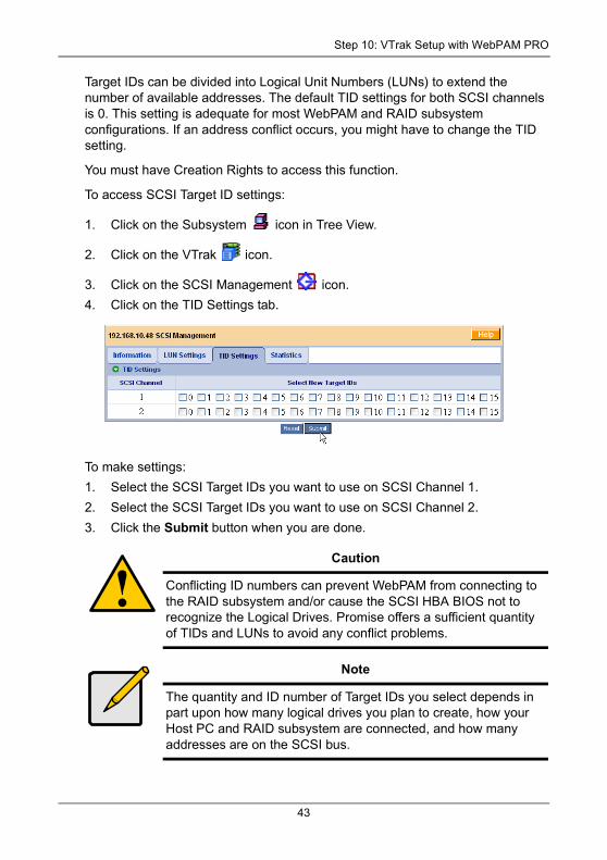
To access SCSI Target ID settings:
1. Click on the Subsystem icon in Tree View.
2. Click on the VTrak icon.
3. Click on the SCSI Management icon.
4. Click on the TID Settings tab.
To make settings:
1. Select the SCSI Target IDs you want to use on SCSI Channel 1.
2. Select the SCSI Target IDs you want to use on SCSI Channel 2.
3. Click the Submit button when you are done.
Caution
Conflicting ID numbers can prevent WebPAM from connecting to the RAID subsystem and/or cause the SCSI HBA BIOS not to recognize the Logical Drives. Promise offers a sufficient quantity of TIDs and LUNs to avoid any conflict problems.
Note
The quantity and ID number of Target IDs you select depends in part upon how many logical drives you plan to create, how your Host PC and RAID subsystem are connected, and how many addresses are on the SCSI bus.
43
VTrak 15110/12100/8110 Quick Start Guide
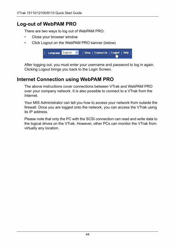
Log-out of WebPAM PROThere are two ways to log out of WebPAM PRO:
• Close your browser window
• Click Logout on the WebPAM PRO banner (below)
After logging out, you must enter your username and password to log in again. Clicking Logout brings you back to the Login Screen.
Internet Connection using WebPAM PROThe above instructions cover connections between VTrak and WebPAM PRO over your company network. It is also possible to connect to a VTrak from the Internet.
Your MIS Administrator can tell you how to access your network from outside the firewall. Once you are logged onto the network, you can access the VTrak using its IP address.
Please note that only the PC with the SCSI connection can read and write data to the logical drives on the VTrak. However, other PCs can monitor the VTrak from virtually any location.
44
Frequently Asked Questions
Frequently Asked QuestionsWhat kind of disk drives can I use with VTrak?
VTrak was designed to use Serial ATA disk drives. You can also use Ultra ATA 133/100/66 disk drives with the optional PATA-to-SATA Adapter available from Promise Technology.
Can I take the disk drives from my UltraTrak, put them into the VTrak and keep my logical drive (array) intact?
Yes. VTrak uses the same logical drive format as UltraTrak. Contact Promise Technology to purchase PATA-to-SATA Adapter for your existing PATA drives.
Can I use my existing SCSI card with VTrak?
If the SCSI card has at least a 160 MB/s data transfer rate, supports LUNs and has a 68-pin VHDCI external connection, you can use it with VTrak.
If your SCSI card has a 68-pin HD external connector, you can purchase an optional 68-pin HDCI to 68-pin VHDCI SCSI cable from Promise Technology.
Will I get maximum performance using my current 80 MB/s SCSI card? Do I have to buy a 160 MB/s SCSI card?
The VTrak has a measured peak sustained throughput of more than 100 MB/s per channel. Using a 80 MB/s SCSI card will result in a performance bottleneck under certain conditions. You must estimate how frequently those conditions happen and how serious they are. Then you can decide whether to upgrade to the faster SCSI card.
How many VTrak subsystems can I connect to one SCSI chain?
You can connect up to eight (8) VTraks on a single SCSI chain.
Can I connect two SCSI cards to the same VTrak?
Yes. VTrak has two SCSI channels, which allows you to connect it to two SCSI cards, whether those cards are in the same PC or two different PCs. For more information, see Chapter 2 of the VTrak User Manual.
Can I connect my VTrak on the same SCSI chain with other devices?
No. Do not connect other devices to the SCSI chain with a VTrak. If you want to monitor your VTrak and run other SCSI devices from the same PC, add another SCSI card to the PC.
45
VTrak 15110/12100/8110 Quick Start Guide
Can I connect my VTrak on the same SCSI chain as my Promise UltraTrak?
No. Do not connect other Promise products to the SCSI chain with a VTrak. If you want to monitor your VTrak and UltraTrak from the same PC, add another SCSI card to the PC.
How can I tell when the VTrak has fully booted?
When the VTrak is fully booted up, the Power, FRU and disk array LEDs will light up green. The Controller LED blinks five times, once per second; goes dark for ten seconds; then blinks five times again.
How do I learn more about configuring and using my VTrak?
Read the VTrak User Manual on the software CD. It contains detailed information regarding configuration, troubleshooting and maintenance of your VTrak.
Why does VTrak come with a Command Line Utility?
First, to assign your VTrak a Management Port IP address in order for the WebPAM PRO management software to connect to it. Second, in the event of a network failure, you can still access the VTrak.
The serial cable is connected, VTrak is running and I used the specified settings but the serial connection does not work. What should I do now?
Access your PC BIOS settings and enable the serial port.
I tried to log into WebPAM PRO but my browser showed the message “cannot be displayed.” What is the problem?
The browser decided prematurely that WebPAM was not responding. Click the Refresh button. This action usually brings up the login screen.
I created a Subystem on WebPAM PRO but when I click on it, nothing happens. What is the problem?
There is a broken network connection between your PC and the VTrak, or the VTrak is powered off. Locate and fix the connection or power on the VTrak, as required.
Can WebPAM PRO connect through VTrak’s Serial (RS-232) port?
No. The VTrak Serial port is only for a HyperTerminal connection.
I can access the VTrak over my company’s intranet. But I can’t access it from an outside Internet connection. How do I make the Internet connection work?
This condition is not related to VTrak, but is due to your firewall and network connection protocol. Contact your MIS Administrator.
46
Frequently Asked Questions
With other Promise products, such as UltraTrak, I used the Host PC’s IP address in WebPAM PRO to connect with the RAID subsystem. Why is VTrak different?
UltraTrak uses In-Band SCSI technology to connect with the Host PC. VTrak connects to the Host PC through a network connection. Therefore, it requires its own IP address. VTrak’s iSCSI connection is used only to move data.
Why can a RAID 1 disk array on VTrak consist of only two disk drives?
On VTrak, RAID 1 disk arrays work in matched pairs. But you are not limited to just one RAID 1 disk array. VTrak supports up to 7 RAID 1 disk arrays, using up to 14 disk drives. Or you can create a single RAID 10 disk array with data mirroring and up to 14 physical drives.
See Chapter 7 of the VTrak User Manual for more information on the number of disk drives you can use for each RAID level.
Are disk arrays on VTrak limited to 2.199 terabytes?
No. The 2.199 TB disk array size limit does not apply to VTrak. Check whether your operating system supports disk arrays over 2.199 TB.
If disk arrays can exceed 2.199 TB on VTrak, why can’t I expand my disk array beyond 2.199 TB?
The problem is a limitation of the Operating System and the number and size of LBA sectors it can manage. See Chapter 7 of the VTrak User Manual for more information and your options for disk array expansion.
The CLU, WebPAM PRO and VTrak documentation use the term “logical drive” where earlier Promise products use the term “array.” Why did this change happen?
A disk array is an organized collection of physical disk drives. Logical drives are made from disk arrays. A logical drive is the entity that your operating system recognizes as a single volume (as if it were a single disk drive). Promise separated the disk array and logical drive functions in order to provide more RAID management options.
I have two UltraTraks and use WebPAM to monitor them. Can I use my existing WebPAM setup to monitor the VTraks also?
No. Install WebPAM PRO from the VTrak Software CD.
The VTrak has no LCD panel. How can I set it up and create disk arrays?
There are two ways to set up VTrak and create disk arrays, using WebPAM PRO or the Command Line Utility. See the VTrak User Manual for more information.
47
VTrak 15110/12100/8110 Quick Start Guide
Why do the Rebuild, Synchronize, Expand and Convert operations take so long compared to moving data?
When data is moved, the operation consists of reading, writing and checking one or more files. Rebuild, Synchronize, Expand and Convert involve reading, writing and checking all the logical block addresses or individual data blocks on each disk drive. Plus, your disk array remains available while these operations take place. These added requirements increase complexity and take more time.
How can I be sure everything is working OK on the VTrak?
VTrak has several LEDs on the front to monitor the status of power, field replaceable units (FRUs) and disk arrays. When these are green, VTrak is functioning normally.
What happens if a disk array goes critical?
On the front of VTrak, the disk array LED turns amber and an audible alarm sounds. This condition is described in Chapter 4 of the VTrak User Manual on the Software CD.
Can VTrak run using just one power supply?
Yes, it is possible to run VTrak on a single power supply. There are two power supplies so that VTrak will continue running if one of the power supply fails. But deliberately leaving one power supply off negates this advantage. Always switch on both power supplies.
Contact Technical SupportPromise Technical Support provides several support options for Promise users to access information and updates. We encourage you to use one of our electronic services, which provide product information updates for the most efficient service and support.
If you decide to contact us, please have the following information available:
• Product model and serial number
• BIOS and driver version numbers
• A description of the problem / situation
• System configuration information, including: motherboard and CPU type, hard drive model(s), SATA/ATA/ATAPI drives & devices, and other controllers.
48
Contact Technical Support
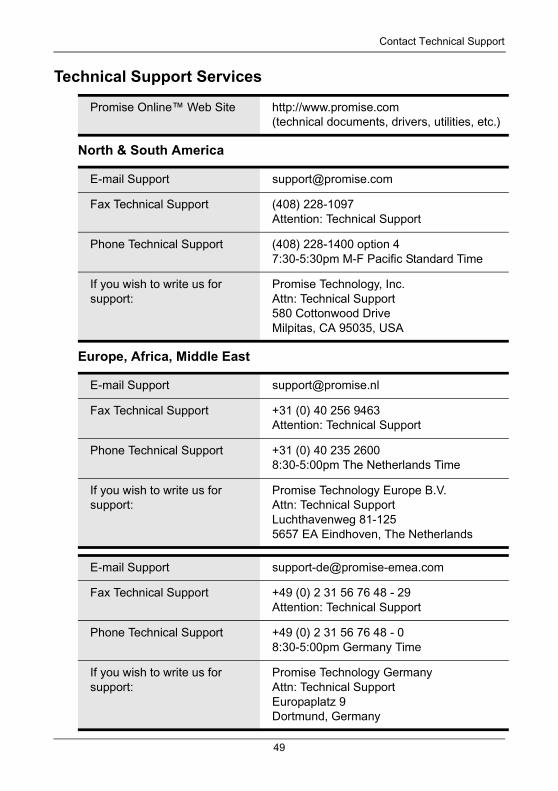
Technical Support Services
North & South America
Europe, Africa, Middle East
Promise Online™ Web Site http://www.promise.com(technical documents, drivers, utilities, etc.)
E-mail Support [email protected]
Fax Technical Support (408) 228-1097 Attention: Technical Support
Phone Technical Support (408) 228-1400 option 47:30-5:30pm M-F Pacific Standard Time
If you wish to write us for support:
Promise Technology, Inc.Attn: Technical Support580 Cottonwood DriveMilpitas, CA 95035, USA
E-mail Support [email protected]
Fax Technical Support +31 (0) 40 256 9463Attention: Technical Support
Phone Technical Support +31 (0) 40 235 26008:30-5:00pm The Netherlands Time
If you wish to write us for support:
Promise Technology Europe B.V.Attn: Technical SupportLuchthavenweg 81-1255657 EA Eindhoven, The Netherlands
E-mail Support [email protected]
Fax Technical Support +49 (0) 2 31 56 76 48 - 29Attention: Technical Support
Phone Technical Support +49 (0) 2 31 56 76 48 - 08:30-5:00pm Germany Time
If you wish to write us for support:
Promise Technology GermanyAttn: Technical SupportEuropaplatz 9Dortmund, Germany
49
VTrak 15110/12100/8110 Quick Start Guide
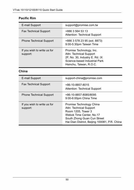
Pacific Rim
China
E-mail Support [email protected]
Fax Technical Support +886 3 564 53 13Attention: Technical Support
Phone Technical Support +886 3 578 23 95 (ext. 8873)9:00-5:30pm Taiwan Time
If you wish to write us for support:
Promise Technology, Inc.Attn: Technical Support 2F, No. 30, Industry E. Rd. IXScience-based Industrial ParkHsinchu, Taiwan, R.O.C.
E-mail Support [email protected]
Fax Technical Support +86-10-8857-8015 Attention: Technical Support
Phone Technical Support +86-10-8857-8085/8095 9:00-6:00pm China Time
If you wish to write us for support:
Promise Technology ChinaAttn: Technical Support Room 1205, Tower 3Webok Time Center, No.17South Zhong Guan Cun StreetHai Dian District, Beijing 100081, P.R. China
50


