Field Service Manual for Vulcan Air/Steam Onshore Hammers VULCAN IRON WORKS INC. P.O. Box 5402 Chattanooga, TN 37406 (800)742-6637 or (423)698-1581 Bulletin 168G 3 April, 1999 US$50.00 UK£25.00 J¥7000
Transcript
Field Service Manual for
Vulcan Air/Steam Onshore Hammers
VULCAN IRON WORKS INC. P.O. Box 5402
Chattanooga, TN 37406 (800)742-6637 or (423)698-1581
Bulletin 168G 3 April, 1999
US$50.00 UK£25.00
J¥7000
VULCAN IRON WORKS INC. (800) 742-6637 or (423)698-1581
Bulletin 168 Page 2 of 60
GENERAL SAFETY INFORMATION
• Pile hammers should be operated only by well trained, experienced personnel. • Operating personnel should review all instructions and safety manuals before using pile hammers.Copies
of all pertinent manuals should be kept with the pile hammer. • Everyone near or on the pile driving site should wear safety clothing, including hard hats, safety shoes,
safety glasses, and hearing protection. • If any operating abnormalities are observed, the hammer should be stopped immediately. • All personnel should stay clear of the work area during operations. • Air or steam hose connections must be properly secured. Never use an air hose to carry steam. If the
hose fails during operation, the results could be extremely dangerous. • Personnel should stay clear of the hammer until the ram is resting on the base. • Fire extinguishers must be kept available at all times. • All federal, state, and local safety and health regulations should be observed. • For additional important safety information, see Section 4 of this manual.
ORDERING PARTS AND ASSEMBLIES
Refer to the parts list and drawing for the size of hammer involved. Locate the item on the drawing. The key (or number) next to the item is the number used in the parts list. Use the EXACT NAME given in the list and the EXACT PART NUMBER.
Part orders must contain the following:
A) SIZE and SERIAL NUMBER of the hammer. B) PART NAME AND PART NUMBER of the item(s). C) Quantity required. Vulcan® is a registered trademark of Vulcan Iron Works Inc. Ezy-Out® is a registered trademark of the Cleveland Twist Drill Co.
WARRANTY
Vulcan Iron Works Inc. warrants these products to be in accordance with our published specifications or those specifications agreed to by Vulcan in writing at the time of the sale. Vulcan makes no other warranty, express or implied. THE IMPLIED WARRANTIES OF MERCHANTABILITY AND OF FITNESS FOR ANY PARTICULAR PURPOSE ARE EXCLUDED FROM THIS WARRANTY. Our obligation and liability under this warranty is expressly limited to repairing or replacing, at Vulcan’s option, any product which fails to meet these specifications within 180 days from date of initial use, but not to exceed one year from date of delivery. This remedy is exclusive and Vulcan’s obligation does not include any transportation charges or costs of installation or any liability from direct, indirect or consequential damage or delay. If requested by Vulcan, products or parts for which a warranty claim is made are to be returned transportation prepaid to Vulcan. Any improper use, operation beyond rated capacity as stated in the written specifications, substitution of parts not approved by Vulcan in writing, or any alteration or repair by anyone other than a duly authorized representative of Vulcan shall void this warranty.
VULCAN IRON WORKS INC. (800) 742-6637 or (423)698-1581
Bulletin 168 Page 3 of 60
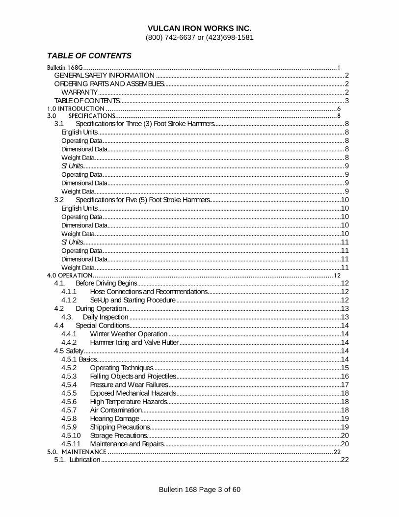
TABLE OF CONTENTS Bulletin 168G.......................................................................................................................................1
GENERAL SAFETY INFORMATION ........................................................................................................................ 2 ORDERING PARTS AND ASSEMBLIES................................................................................................................... 2
WARRANTY ............................................................................................................................................................. 2 TABLE OF CONTENTS............................................................................................................................................... 3
3.1 Specifications for Three (3) Foot Stroke Hammers................................................................................... 8 English Units ............................................................................................................................................................. 8 Operating Data.......................................................................................................................................................... 8 Dimensional Data....................................................................................................................................................... 8 Weight Data............................................................................................................................................................... 8 SI Units....................................................................................................................................................................... 9 Operating Data.......................................................................................................................................................... 9 Dimensional Data....................................................................................................................................................... 9 Weight Data............................................................................................................................................................... 9
3.2 Specifications for Five (5) Foot Stroke Hammers....................................................................................10 English Units ...........................................................................................................................................................10 Operating Data........................................................................................................................................................10 Dimensional Data.....................................................................................................................................................10 Weight Data.............................................................................................................................................................10 SI Units.....................................................................................................................................................................11 Operating Data........................................................................................................................................................11 Dimensional Data.....................................................................................................................................................11 Weight Data.............................................................................................................................................................11
4.0 OPERATION................................................................................................................................12 4.1. Before Driving Begins ..................................................................................................................................12
4.1.1 Hose Connections and Recommendations .....................................................................................12 4.1.2 Set-Up and Starting Procedure .........................................................................................................12
4.2 During Operation.........................................................................................................................................13 4.3. Daily Inspection .......................................................................................................................................13
4.4 Special Conditions.......................................................................................................................................14 4.4.1 Winter Weather Operation ..............................................................................................................14 4.4.2 Hammer Icing and Valve Flutter .......................................................................................................14
4.5 Safety....................................................................................................................................................................14 4.5.1 Basics............................................................................................................................................................14 4.5.2 Operating Techniques........................................................................................................................15 4.5.3 Falling Objects and Projectiles .........................................................................................................16 4.5.4 Pressure and Wear Failures ..............................................................................................................17 4.5.5 Exposed Mechanical Hazards .........................................................................................................18 4.5.6 High Temperature Hazards...............................................................................................................18 4.5.7 Air Contamination...............................................................................................................................18 4.5.8 Hearing Damage ................................................................................................................................19 4.5.9 Shipping Precautions..........................................................................................................................19 4.5.10 Storage Precautions............................................................................................................................20 4.5.11 Maintenance and Repairs .................................................................................................................20
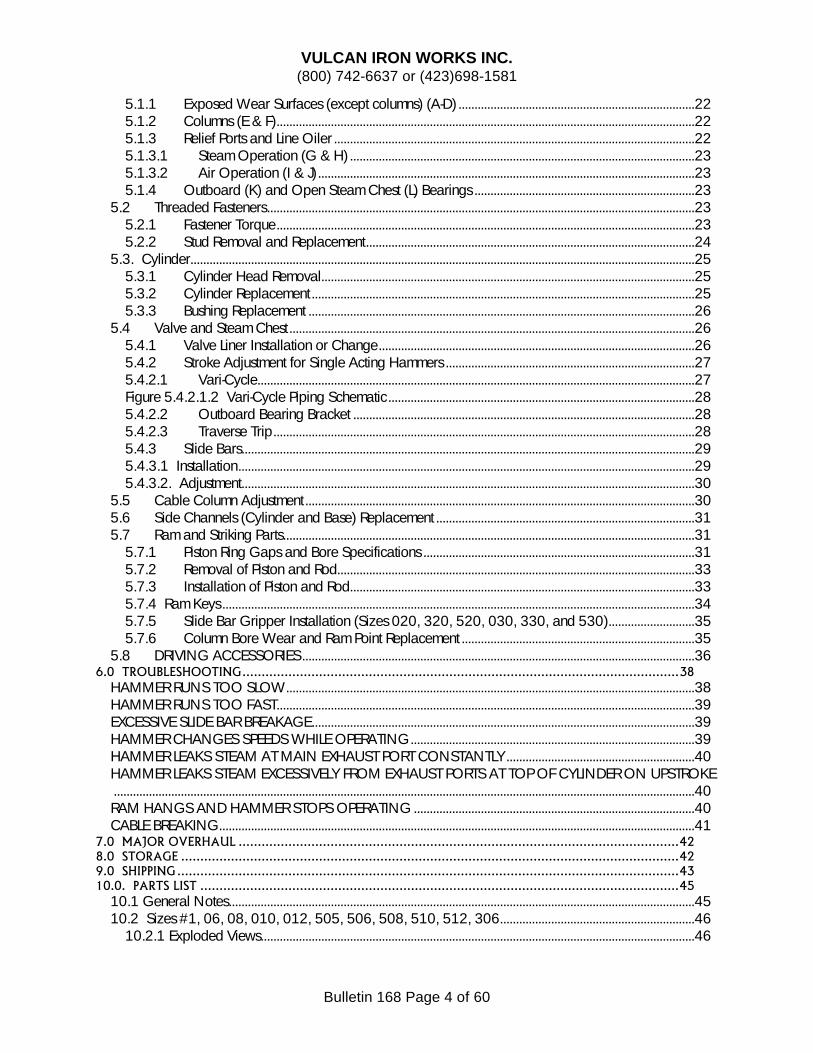
5.5 Cable Column Adjustment ..........................................................................................................................30 5.6 Side Channels (Cylinder and Base) Replacement .................................................................................31 5.7 Ram and Striking Parts.................................................................................................................................31
5.7.1 Piston Ring Gaps and Bore Specifications .....................................................................................31 5.7.2 Removal of Piston and Rod................................................................................................................33 5.7.3 Installation of Piston and Rod............................................................................................................33 5.7.4 Ram Keys ....................................................................................................................................................34 5.7.5 Slide Bar Gripper Installation (Sizes 020, 320, 520, 030, 330, and 530)...........................35 5.7.6 Column Bore Wear and Ram Point Replacement .........................................................................35
HAMMER RUNS TOO SLOW................................................................................................................................38 HAMMER RUNS TOO FAST...................................................................................................................................39 EXCESSIVE SLIDE BAR BREAKAGE........................................................................................................................39 HAMMER CHANGES SPEEDS WHILE OPERATING.........................................................................................39 HAMMER LEAKS STEAM AT MAIN EXHAUST PORT CONSTANTLY ...........................................................40 HAMMER LEAKS STEAM EXCESSIVELY FROM EXHAUST PORTS AT TOP OF CYLINDER ON UPSTROKE......................................................................................................................................................................................40 RAM HANGS AND HAMMER STOPS OPERATING ........................................................................................40 CABLE BREAKING.....................................................................................................................................................41
7.0 MAJOR OVERHAUL ...................................................................................................................42 8.0 STORAGE ..................................................................................................................................42 9.0 SHIPPING...................................................................................................................................43 10.0. PARTS LIST .............................................................................................................................45
VULCAN IRON WORKS INC. (800) 742-6637 or (423)698-1581
Bulletin 168 Page 5 of 60
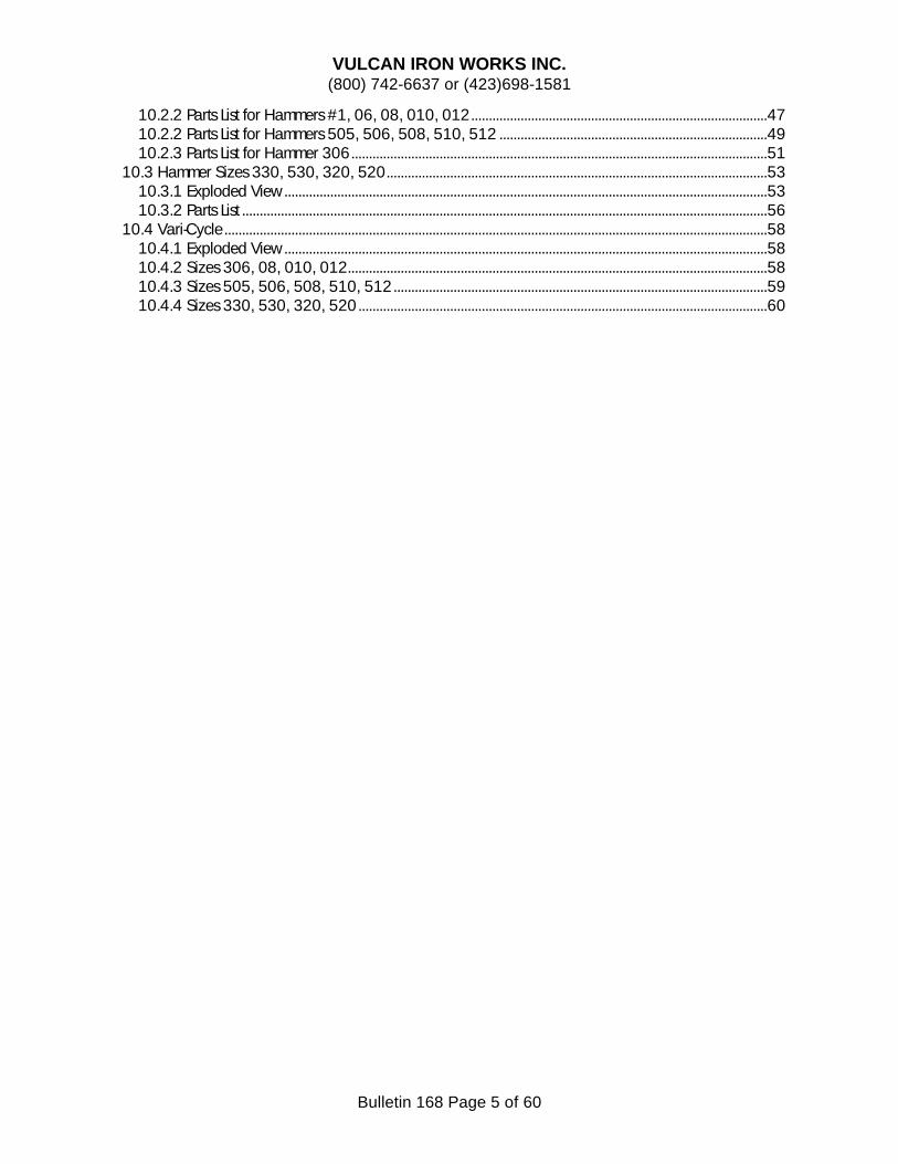
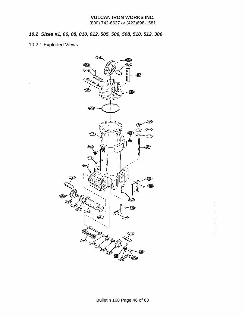
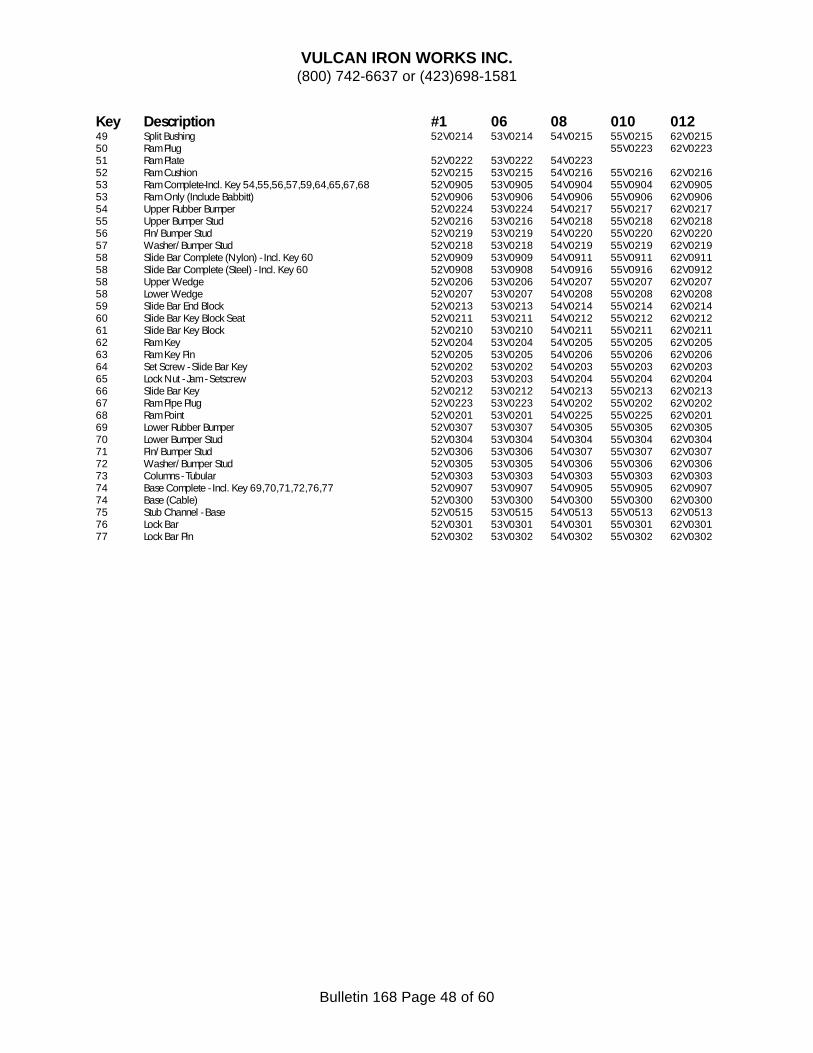
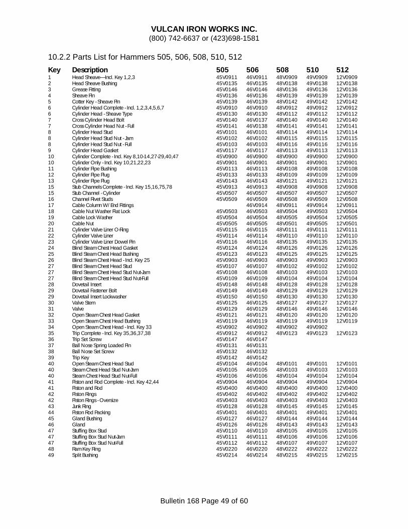
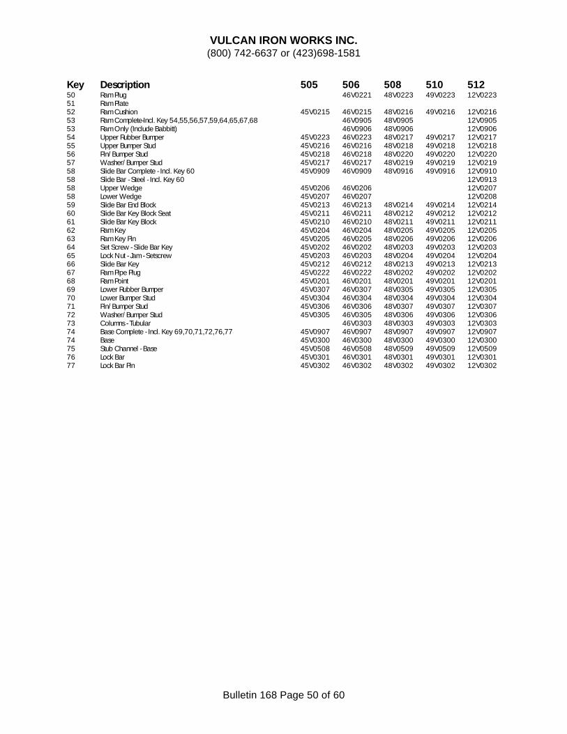
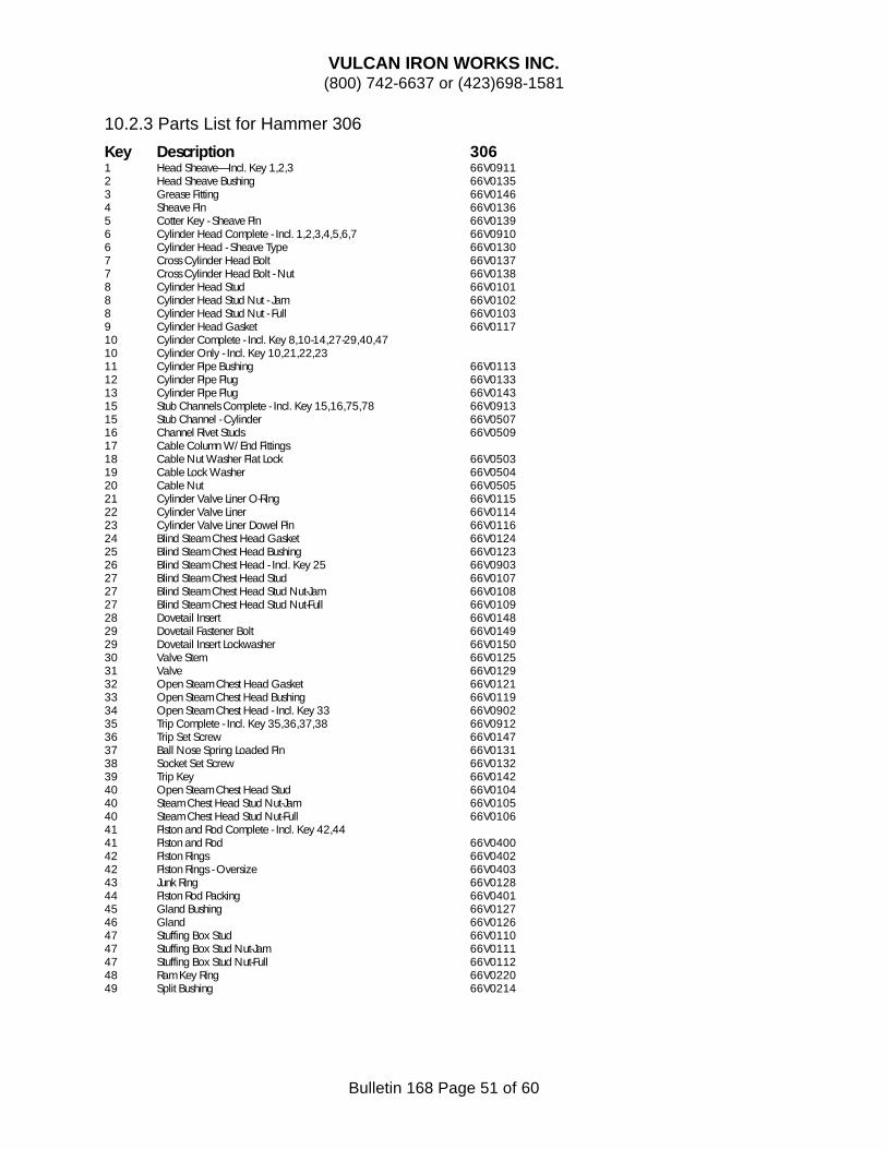
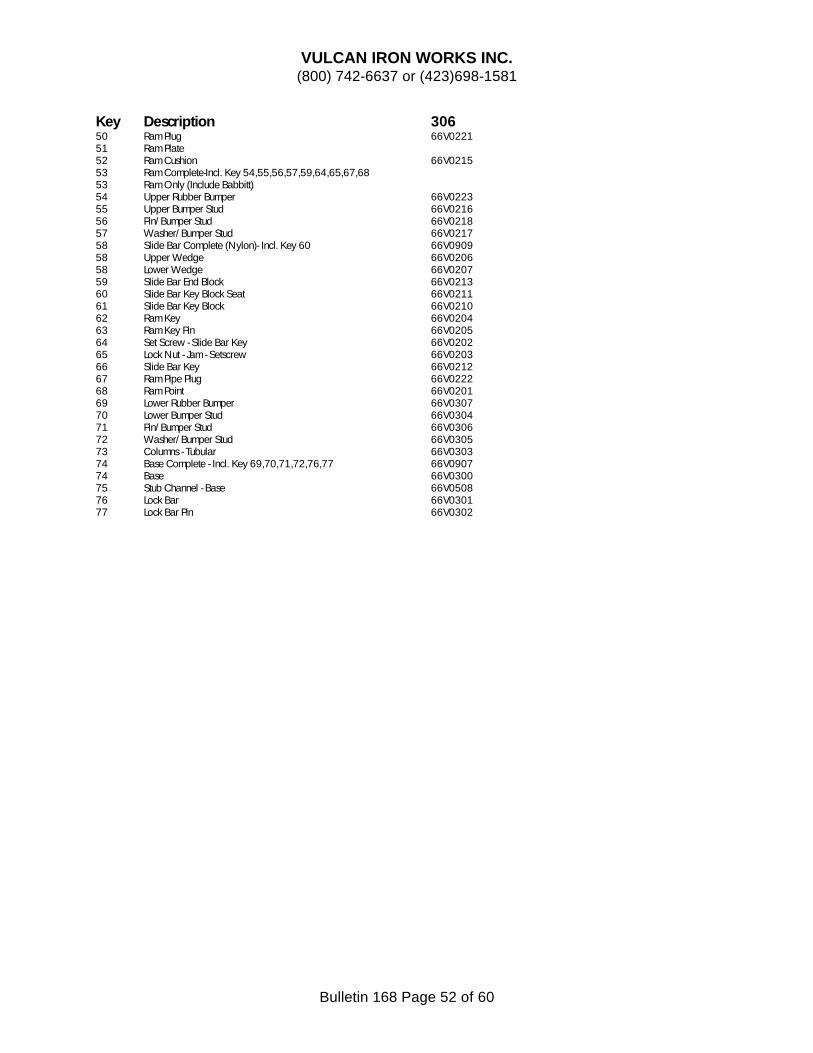
10.2.2 Parts List for Hammers #1, 06, 08, 010, 012....................................................................................47 10.2.2 Parts List for Hammers 505, 506, 508, 510, 512 ............................................................................49 10.2.3 Parts List for Hammer 306......................................................................................................................51
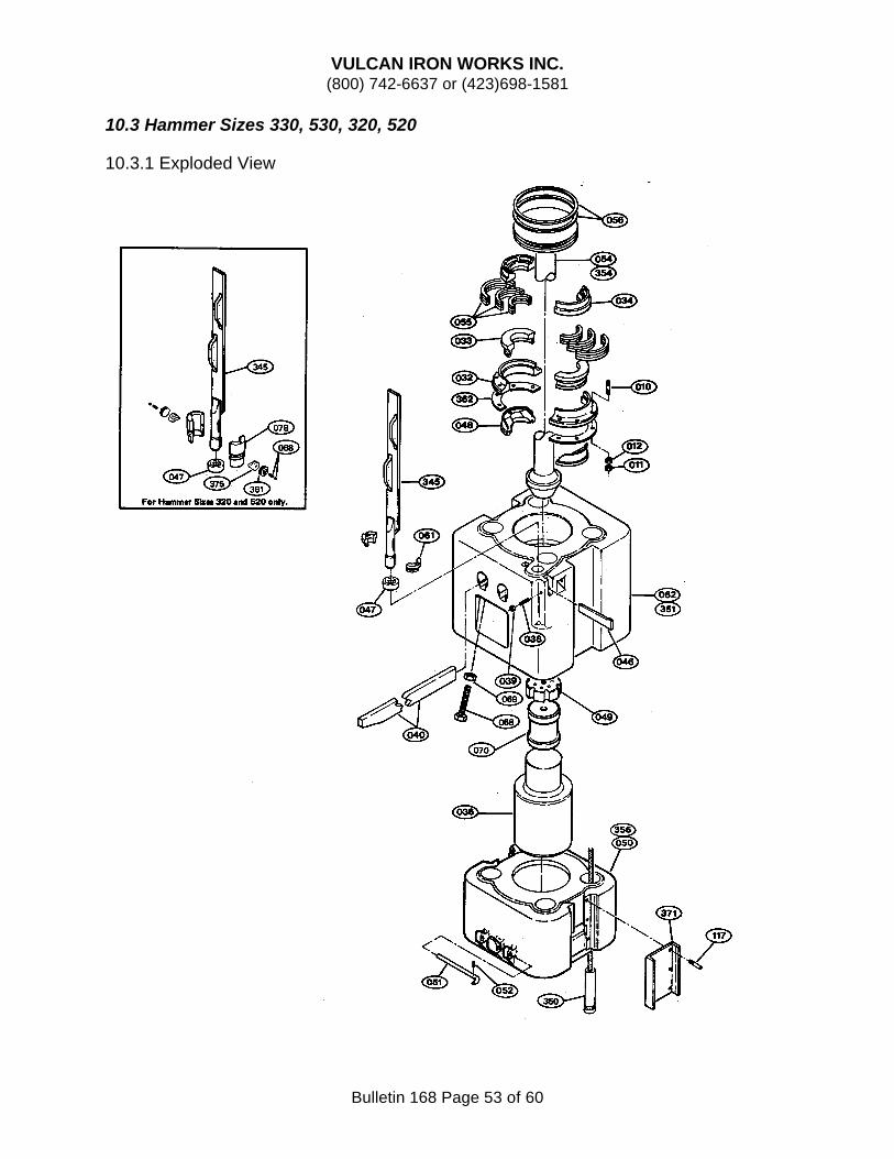
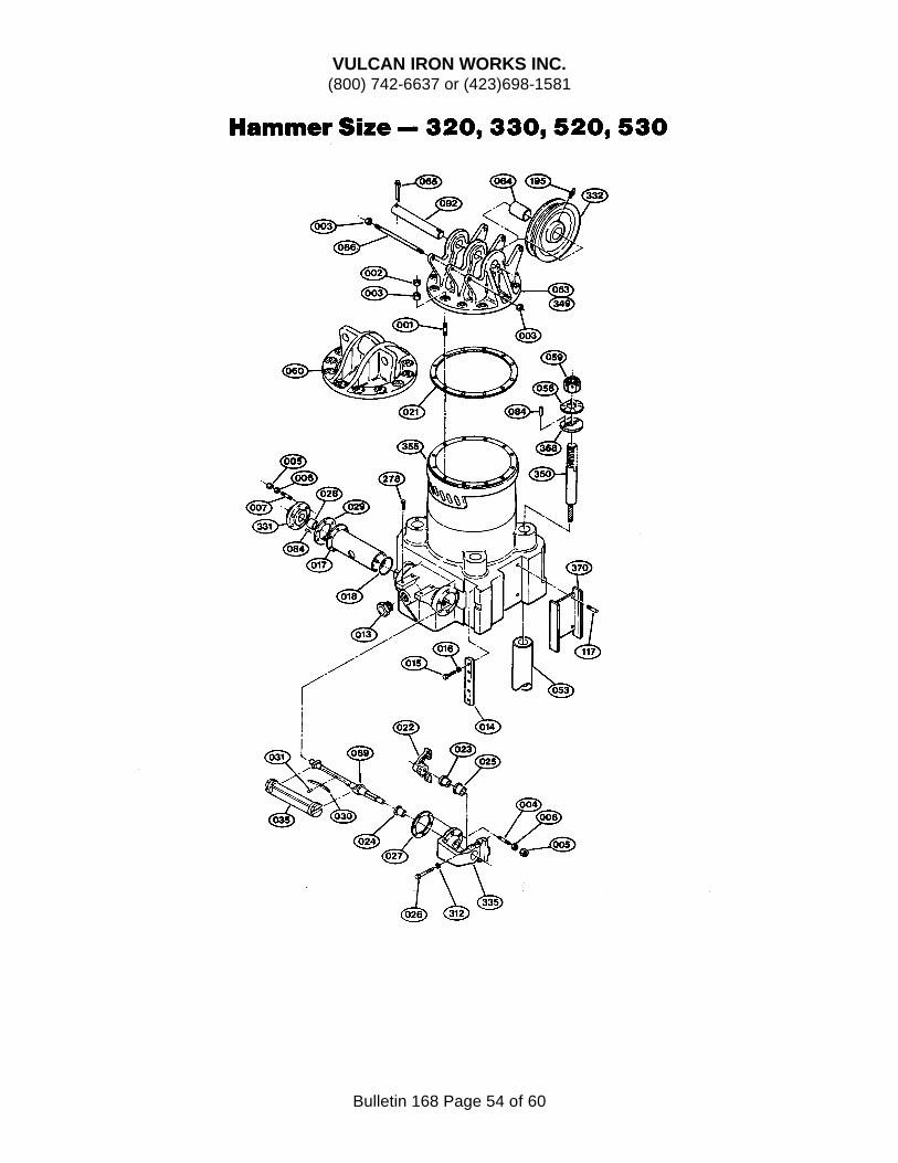
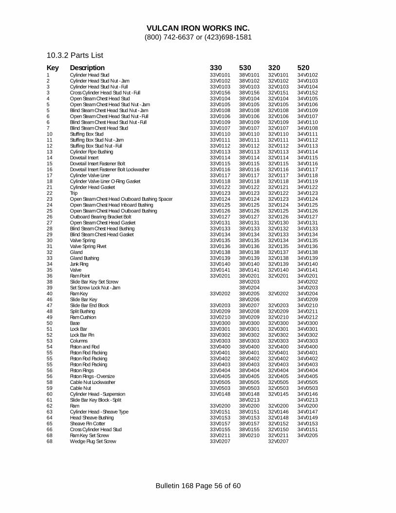
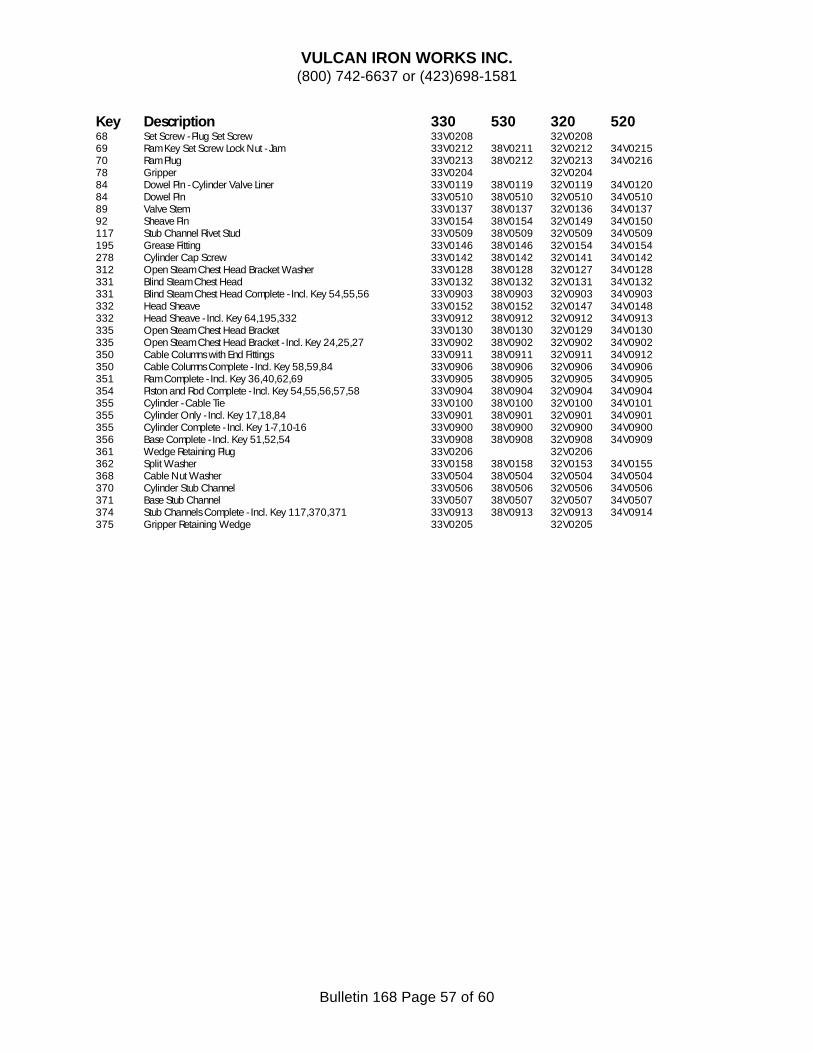
10.3 Hammer Sizes 330, 530, 320, 520............................................................................................................53 10.3.1 Exploded View .........................................................................................................................................53 10.3.2 Parts List .....................................................................................................................................................56
VULCAN IRON WORKS INC. (800) 742-6637 or (423)698-1581
Bulletin 168 Page 6 of 60
1.0 INTRODUCTION The field service manual has been prepared to provide helpful and necessary instructions for the operation, and maintenance of your VULCAN pile hammers. The different sizes covered in this manual are No’s 1, 505, 06, 306, 506, 08, 508, 010, 510, 012, 512, 320, 330, 520 and 530 Single Acting Hammers.
Unless specified, the procedures and instructions given are applicable to all sizes. When the instructions are different between the sizes, the beginning of the instruction will indicate which size(s) are covered by the information.
Read the information carefully, follow the instructions properly and your pile hammers should deliver many years of safe and dependable service. The instructions given herein are the result of careful correlation between factory and field experience, and cover the best methods for operation, maintenance, lubrication and overhaul of VULCAN hammers.
Care has been taken to avoid undue emphasis of minor details, but when minor items have been emphasized it is because experience has indicated the wisdom of giving these points special attention.
For safe operation and correct maintenance procedure, it is recommended that the instructions given herein be carefully followed. Service and repair, other than those covered in this manual, are not recommended to be attempted outside of the factory. The manufacturer advocates that major overhaul of a hammer be accomplished by an authorized representative of the VULCAN IRON WORKS INC. or shipped directly to the factory. IT IS IMPORTANT THAT NO UNNECESSARY OR UNAUTHORIZED SERVICE BE PERFORMED ON THE HAMMERS AS THIS TYPE OF SERVICE HAS, IN MOST CASES, BEEN FOUND TO BE DETRIMENTAL.
It has been the aim of the manufacturer to build a hammer to give maximum service with minimum attention other than proper lubrication and adjustments. The latest engineering knowledge and design has been combined with the best
materials obtainable and finest workmanship possible to attain high quality products.
DETAILED OPERATION, MAINTENANCE AND LUBRICATION INSTRUCTIONS IN THIS MANUAL ARE VERY IMPORTANT, and you cannot expect good service from your hammer unless the instructions are followed carefully.
All of the instructions have been made as concise as possible and the few minutes required to read them can save down time and money in the future.
(Section 2.0 is reserved for future use.)
VULCAN IRON WORKS INC. (800) 742-6637 or (423)698-1581
Bulletin 168 Page 8 of 60
3.0 SPECIFICATIONS
3.1 Specifications for Three (3) Foot Stroke Hammers
English Units #1 06 08 010 012 320 330
Operating Data
Rated Striking Energy, ft-lbs 15,000 19,500 26,000 32,500 39,000 60,000 90,000 Blows per Minute, Normal Stroke, No Set
60 60 50 50 50 55 54
Normal Stroke, Inches 36 36 39 39 39 36 36 Rated Operating Pressure at Hammer, psi
Bore, mm 343 343 419 419 419 552 552 Net Area of Piston, sq. cm. 861.4 861.4 1276.9 1276.9 1276.9 2166.1 2166.1 Length of Hammer (overall), m 3886 3886 4521 4750 4750 5321 5321 Distance Across Female Jaws, mm 508 508 660 660 660 940 940 Width of Female Jaws, mm 210 210 235 235 235 286 286 Largest Outside Diameter of Pile, mm
457 457 610 610 610 864 864
Size of Hose, mm 51 51 64 64 64 76 76
Weight Data
Weight of Striking Parts, kg 2,268 2,948 3,629 4,536 5,443 9,072 13,608 Net Weight of Hammer, kg 4,400 5,080 7,598 8,505 9,412 19,731 24,267 Shipping Weight of Hammer, kg 4,581 5,488 7,938 8,845 9,752 20,366 24,948
VULCAN IRON WORKS INC. (800) 742-6637 or (423)698-1581
Bulletin 168 Page 10 of 60
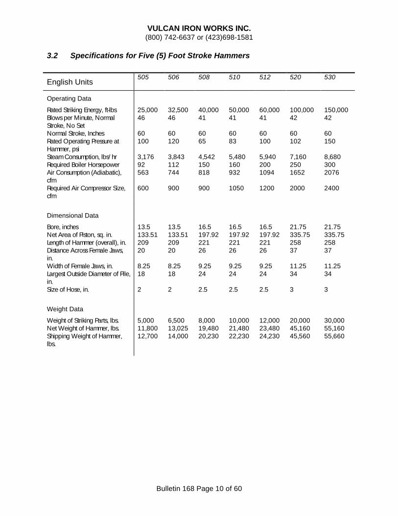
3.2 Specifications for Five (5) Foot Stroke Hammers
English Units 505 506 508 510 512 520 530
Operating Data
Rated Striking Energy, ft-lbs 25,000 32,500 40,000 50,000 60,000 100,000 150,000 Blows per Minute, Normal Stroke, No Set
46 46 41 41 41 42 42
Normal Stroke, Inches 60 60 60 60 60 60 60 Rated Operating Pressure at Hammer, psi
Bore, inches 13.5 13.5 16.5 16.5 16.5 21.75 21.75 Net Area of Piston, sq. in. 133.51 133.51 197.92 197.92 197.92 335.75 335.75 Length of Hammer (overall), in. 209 209 221 221 221 258 258 Distance Across Female Jaws, in.
20 20 26 26 26 37 37
Width of Female Jaws, in. 8.25 8.25 9.25 9.25 9.25 11.25 11.25 Largest Outside Diameter of Pile, in.
18 18 24 24 24 34 34
Size of Hose, in. 2 2 2.5 2.5 2.5 3 3
Weight Data
Weight of Striking Parts, lbs. 5,000 6,500 8,000 10,000 12,000 20,000 30,000 Net Weight of Hammer, lbs. 11,800 13,025 19,480 21,480 23,480 45,160 55,160 Shipping Weight of Hammer, lbs.
12,700 14,000 20,230 22,230 24,230 45,560 55,660
VULCAN IRON WORKS INC. (800) 742-6637 or (423)698-1581
Bulletin 168 Page 11 of 60
SI Units
Operating Data
Rated Striking Energy, kJ 33.9 44.1 54.2 67.8 81.3 135.6 203.4 Blows per Minute, Normal Stroke, No Set
46 46 41 41 41 42 42
Normal Stroke, mm 1524 1524 1524 1524 1524 1524 1524 Rated Operating Pressure at Hammer, bar
Bore, mm 343 343 419 419 419 552 552 Net Area of Piston, sq. cm. 861.4 861.4 1276.9 1276.9 1276.9 2166.1 2166.1 Length of Hammer (overall), m 5309 5309 5613 5613 5613 6553 6553 Distance Across Female Jaws, mm
508 508 660 660 660 940 940
Width of Female Jaws, mm 210 210 235 235 235 286 286 Largest Outside Diameter of Pile, mm
457 457 610 610 610 864 864
Size of Hose, mm 51 51 64 64 64 76 76
Weight Data
Weight of Striking Parts, kg 2,268 2,948 3,629 4,536 5,443 9,072 13,608 Net Weight of Hammer, kg 5,352 5,908 8,836 9,743 10,650 20,484 25,020 Shipping Weight of Hammer, kg 5,761 6,350 9,176 10,083 10,991 20,666 25,247
VULCAN IRON WORKS INC. (800) 742-6637 or (423)698-1581
Bulletin 168 Page 12 of 60
4.0 OPERATION
4.1. Before Driving Begins
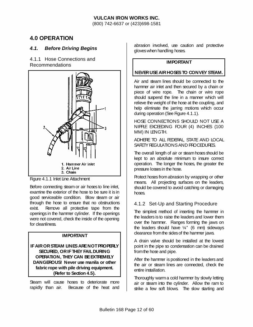
4.1.1 Hose Connections and Recommendations
Figure 4.1.1 Inlet Line Attachment
Before connecting steam or air hoses to line inlet, examine the exterior of the hose to be sure it is in good serviceable condition. Blow steam or air through the hose to ensure that no obstructions exist. Remove all protective tape from the openings in the hammer cylinder. If the openings were not covered, check the inside of the opening for cleanliness.
IMPORTANT
IF AIR OR STEAM LINES ARE NOT PROPERLY SECURED, OR IF THEY FAIL DURING
OPERATION, THEY CAN BE EXTREMELY DANGEROUS! Never use manila or other
fabric rope with pile driving equipment. (Refer to Section 4.5).
Steam will cause hoses to deteriorate more rapidly than air. Because of the heat and
abrasion involved, use caution and protective gloves when handling hoses.
IMPORTANT
NEVER USE AIR HOSES TO CONVEY STEAM.
Air and steam lines should be connected to the hammer air inlet and then secured by a chain or piece of wire rope. The chain or wire rope should suspend the line in a manner which will relieve the weight of the hose at the coupling, and help eliminate the jarring motions which occur during operation (See Figure 4.1.1).
HOSE CONNECTIONS SHOULD NOT USE A NIPPLE EXCEEDING FOUR (4) INCHES (100 MM) IN LENGTH.
ADHERE TO ALL FEDERAL, STATE AND LOCAL SAFETY REGULATIONS AND PROCEDURES.
The overall length of air or steam hoses should be kept to an absolute minimum to insure correct operation. The longer the hoses, the greater the pressure losses in the hose.
Protect hoses from abrasion by wrapping or other means. All projecting surfaces on the leaders, should be covered to avoid catching or damaging hoses.
4.1.2 Set-Up and Starting Procedure
The simplest method of inserting the hammer in the leaders is to raise the leaders and lower them over the hammer. Flanges forming the jaws on the leaders should have ¼” (6 mm) sideways clearance from the sides of the hammer jaws.
A drain valve should be installed at the lowest point in the pipe so condensation can be drained from the hose and pipe.
After the hammer is positioned in the leaders and the air or steam lines are connected, check the entire installation.
Thoroughly warm a cold hammer by slowly letting air or steam into the cylinder. Allow the ram to strike a few soft blows. The slow starting and
VULCAN IRON WORKS INC. (800) 742-6637 or (423)698-1581
Bulletin 168 Page 13 of 60
warming will permit uniform casting expansion and reduce internal stresses.
4.2 During Operation
As the hammer drives the pile, there are a few things the operator(s) need to watch for.
First, it is important that the hammer produce the desired stroke. This can be either the full stroke or a reduced stroke selected using the Vari-Cycle (see Section 5.4.2). This is the most important criterion in determining whether a hammer is operating properly or not; other criterion, such as blow rate or the “rhythm” of the hammer, are simply not adequate.
Second, the operator must avoid pile runout. This takes place when the driving is very soft. Extensive hammer damage can take place if the hammer at full energy is allowed to drive the pile while it is running. This is because the pile is leaving the hammer faster than the hammer can follow, leading the ram to transfer all of the energy to the base and/or pipe cap. It is permissible to reduce pressure during runout to reduce the stroke temporarily until sufficient ground resistance is encountered.
Third, and the opposite of runout, the operator must avoid driving beyond the rated capacity of the hammer. For Vulcan onshore hammers, this means that the set of the pile must be more than 0.1” (2.54 mm) per blow, or 120 BPF. Any operation above this capacity will void the warranty. Cushion material must be kept fresh as well. Do not continue driving a pile when it is no longer moving as both damage to the pile and hammer will result.
Finally, the operator must take steps to avoid hammer racking due to excessive elastic compression of the pile. Although piles are made of “rigid” materials, such as wood, concrete, or steel, all of these are capable of and do experience elastic compression when they are struck on the end, especially if they are light cross-section piles. Such piles as long and light H-beam, pipe, and wood piles are especially prone to this, and also any type of piles when there is hard driving with most of the pile out of the
ground. Again steps need to be taken to reduce the stroke of the hammer to avoid this problem.
4.3. Daily Inspection
The following items should be checked on the hammer assembly each day the hammer is in use and especially when the hammer has not been used and it is about ready to start driving:
1) Remove all protective tape or rags found in or over port openings of any kind in the cylinder. Should any of the port openings be found to be unprotected, check to be sure no foreign material has entered through the opening.
2) Check clearance between hammer and pipe cap jaws and the leader tracks, especially where the leader tracks have been bent. Hammer and cap must slide freely in the leaders. Make sure that the jaws and tracks are fully greased.
3) Check the columns and piston rods for nicks, burrs, and welding and burning slag.
4) Consult the Lubrication Section of the manual (See Section 5.1) for lubrication instructions. It is very important that the hammer be fully lubricated whenever operated.
5) Fill the steam line oiler, following the lubrication recommendations (See Section 5.1). Make sure the line oiler is properly operating and injecting lubricant into the steam line.
6) Fill the cushion pot on the driving accessory with cushion material and top plate (See Section 5.8).
7) Make sure the steam line and air hoses are completely clear of foreign matter before attaching these to the hammer, (See Section 4.1).
8) Secure the steam or air supply line to the hammer (See Section 4.1).
9) Check all fasteners for tightness (See Section 5.3.1.1).
10) Check all gaskets for breaks or leaks. 11) Check the tie cables for tightness. Check the
general condition of all suspension and wrap cables.
12) Check ram keys for tightness (See Section 5.7.2). DO NOT OVERTIGHTEN THE RAM KEYS.
VULCAN IRON WORKS INC. (800) 742-6637 or (423)698-1581
Bulletin 168 Page 14 of 60
13) Check slide bar to make sure that it is secure (See Section 5.4.3).
14) Check drive cap-hammer base wire ropes to make sure that they are safe.
When the leaders are fully secured to the crane line, the hammer may be lifted onto the pile. For plumb pile, even though the hammer alignment must always be correct, the specific rotation of the hammer is not critical; however, with batter pile, the hammer should be positioned in such a way that the weight of the ram is evenly distributed on at least two (2) columns. Failure to do so may result in the one (1) column being galled and scored.
The hammer hoist line should be kept slack at all times while the pile is being driven so the full weight of the hammer rest squarely on the pile. A pile which is allowed to run ahead of the hammer will permit the hammer to drive on its own retaining members, damaging the hammer.
4.4 Special Conditions
4.4.1 Winter Weather Operation
During severe cold weather it may be necessary to preheat the cylinder and other lubricated parts with a torch. Warming will help thaw the oil and break the bond which would prevent the hammer from starting.
IMPORTANT
Keep heat away from nylon slide bars and cables.
Condensation will form in the cylinder and steam chest during cold weather. Sluggish performance will be noticeable until the condensate can drain out of the cylinder. Drainage is automatic.
To decrease the intensity of the hammer driving force, the steam or air pressure can be reduced during operation. Steam or air pressure reduction can be accomplished at the operator throttle valve, the air compressor, or steam boiler.
In sub-freezing weather the hammer must be preheated prior to operation. Pre-heating will prevent damage to the cylinder and valve by
eliminating frozen condensation and possible thermal shock.
Drain any accumulated condensation from the lubricator at the end of each work shift, to avoid ice from plugging the oil suction line. It is also advisable to preheat the lubricator to assure immediate lubrication when the hammer is started.
Insulate any hard piping to minimize air volume losses due to cold temperature.
4.4.2 Hammer Icing and Valve Flutter
One phenomenon frequently associated with cold weather operation is valve flutter, which is usually attributed to hammer icing in compressed air. Valve flutter is not exclusively associated with winter, however; if the temperature and humidity are right, hammer icing can take place in hot weather as well as cold. To avoid icing, several remedies exist:
1) A heater can be installed in the air compressor to heat air enough to eliminate ice formations.
2) The lubrication oil in the air line oiler can be diluted with 50 percent mixture of ethylene glycol and oil. There are other commercially available products, such as Kilfrost, that can be used to reduce icing.
3) A de-icing unit can be installed in the air line between the lubricator and the hammer. One such unit is the Tanner De-Icer Tank. This unit atomizes an anti-icing chemical into the airstream to prevent hammer icing. Tanner gas equipment is available from Tanner Systems, Inc., Sauk Rapids, MN 56379.
Strange as it may sound, “icing” is not always caused by ice. The same results can be obtained by using motor oil in the line oiler (see Section 5.1). This produces a gooey slime that can break the friction necessary for stable valve operation.
4.5 Safety
4.5.1 Basics
Today’s Vulcan Pile Hammer is the product of over one hundred years of engineering and manufacturing experience. Every component of the machine has been designed for maximum
VULCAN IRON WORKS INC. (800) 742-6637 or (423)698-1581
Bulletin 168 Page 15 of 60
reliability and is fabricated from the most suitable materials available. Although we feel this machine has earned a reputation within the construction industry for both reliability and safety, we also feel that it is our duty to convey to you potential hazards associated with its use.
This section presents a discussion of each of the general types of hazards which must be considered for the successful use of the Vulcan Pile Hammer. Although considerable effort has been made to identify situations which may involve risk to personnel or property and to suggest how these risks may be avoided, nothing will substitute for good maintenance and well trained operators.
4.5.2 Operating Techniques
The pile hammer should be used only by well trained and experienced personnel. Before using the hammer all instruction and safety manuals should be thoroughly reviewed by all operating and maintenance personnel. These references are an invaluable source of information and should be retained by the owner for future study and to train new employees. Copies of these manuals should be kept with the hammer at the construction site for ready access. Additional copies are available from Vulcan.
Safe use of the pile hammer, as with any machine, is dependent upon the skill, knowledge and concern of those who maintain and use it. Because of the wide variety of environments and applications in which this machine may be used, a comprehensive description of detailed rigging and operating techniques within this book is not possible. (Specific requirements should be addressed to Vulcan’s engineering department in Chattanooga, Tennessee.)
For reasons mentioned elsewhere, no one should be any closer to the hammer during driving than is absolutely essential. All workmen should wear safety clothing including hard hats, safety shoes, safety glasses and hearing protection.
Before, and periodically during usage, a complete inspection should be performed on the hammer and all associated equipment to insure operational integrity. The associated equipment
includes items such as the compressor and/or boiler, hoses and hose couplings, leaders, support and lifting equipment and all rigging, etc. On the hammer, particular attention should be given to sheaves, pins, retaining bolts, hose couplings, the valve mechanism, all keys, ram point, pile cap, and the lifting points. Supervisors should be certain that all inspection and maintenance is properly done.
During the driving operation and whenever the hammer is moved, constant supervision and inspection should be provided. If abnormalities are observed, driving should be stopped immediately. One example would be that of the loss of one or more ram keys. If both keys are missing, then the ram would obviously no longer be connected to the piston. Without the ram to slow the acceleration of the piston on the up stroke, the piston may impact into the cylinder head with catastrophic effects. Another dangerous situation would be to continue hammer operation without a piling seated in the pile cap. In this event, the entire force of the falling ram could be absorbed by the hammer’s columns, base and pile cap. Few such strokes could be sustained without severe damage to the hammer. Obviously, such destruction would be hazardous to anyone in the vicinity. Also, the cylinder head lifting points (sheave, axle, pins, keys and nuts) should be continuously checked for worn, loose or missing parts. Damaged or missing components of this assembly could cause hammer to disconnect from rigging and fall.
The effects of unregulated steam or air pressure may also create a risk. As noted elsewhere, failure of any of the hose couplings, while under pressure, could be very dangerous. In addition, operation at pressures either higher or lower than specified design should be avoided since structural damage to the hammer or inefficient operation may result. Obviously, all air or steam supply hoses must be properly sized to avoid undue flow restrictions.
Damage to the pile, pile cap, ram point and piston can occur if the alignment of the hammer and the pile is not correct. That is, the central axis of the hammer should be in alignment with the central axis of the pile and the pile end should be
VULCAN IRON WORKS INC. (800) 742-6637 or (423)698-1581
Bulletin 168 Page 16 of 60
square and uniform. If the error in alignment is great, the hammer will receive an unbalanced structural loading which could result in either a fatigue failure in the hammer or a significant shortening of its useful life. Obviously, this type of condition could be both expensive and dangerous, but can be avoided with reasonable care.
A common pile driving criterion is to drive until a certain number of blows per foot of pile insertion is achieved. This measure is based on the amount of energy delivered with each stroke of the ram. In a single acting hammer, the energy is dependent upon the falling weight and stroke length. Since falling weight is constant, only changes in stroke length can affect the energy delivered. Therefore, if a variable stroke hammer is used, it should be noted that the blow count taken is compared to the proper stroke energy, i.e., the blow count criterion will vary with the stroke length used. The supervisor should correlate the blow count criterion and the stroke length. Otherwise, pile and/or hammer damage, added expense, or inadequate pile installation could result. It should also be noted that significant deviations in pressure delivered to the hammer from the recommended pressure may affect the actual operating stroke length and thus influence the energy in each blow of the hammer.
Since the pile hammer is such an extremely powerful machine, it is conceivable that even with normal operation, surroundings at the driving site could be damaged. Operators should take every precaution to see that exhaust from the hammer and vibration of the earth are not a threat to the area surrounding the driving site. Failure to do so could be unsafe and possibly lead to expensive property damage.
As an additional precautionary measure, a pre-pile driving survey could be made.
Given the respect it deserves, the pile hammer should provide years of safe service. However, the ultimate safety and reliability of the hammer rest in the hands of the user.
4.5.3 Falling Objects and Projectiles
The pile hammer is a relatively large and heavy machine which is normally used in a suspended position. Consequently, gravity can propel the hammer or any of its parts downward with great force. Therefore, every effort should be made to see that neither the machine or any of the hammer’s component parts are permitted to fall.
Supporting and lifting tackle should be of sufficient capacity to safely lift the weight of the hammer and to withstand the vibration of its operation. (See gross weight label on machine.) Likewise, all rigging should be heavy enough to handle the load safely and the entire system should be thoroughly inspected to insure its integrity before it is used. Refer to relevant standards such as A.N.S.I. B-305; O.S.H.A. 1926.251 and 1926.251; P.S.C.A.#1; C.A.G.I #1.
Since the hammer may be suspended well above the work level, all personnel should remain clear of the area. Barricades could be set up around the area for additional safety. Even an object such as a stone, bolt, or scrap may adhere to the hammer when laid down and if dropped from the hammer’s suspended height could cause harm. In addition to remaining clear of the area, steps should be taken to prevent any parts from dropping into the system. Such things as bolts, nuts, keys, fasteners, wedges and couplings should be tightened and checked before each use and after each drive during use. Good maintenance cannot be overemphasized in promoting the safe and efficient use of the hammer.
In addition to free falling objects, it is possible that projectiles can be thrown out during operation. Any foreign material in the lubricant, supply hose or cylinder may be ejected through the exhaust at high velocity. Personnel should therefore remain clear of the exhaust to avoid this risk as well as to avoid being burned by the exhaust steam or air.
If the air or steam lines are either not properly secured by chain or heavy rope, or if they fail in use they can become extremely dangerous. To reduce the risk of this occurring, all couplings should be checked before use and all hoses must
VULCAN IRON WORKS INC. (800) 742-6637 or (423)698-1581
Bulletin 168 Page 17 of 60
be secured to the hammer just below the couplings. Refer to O.S.H.A. Standards 1926.603 (a) (9) (10). This will prevent the hose from whipping wildly over a great distance if the coupling should fail.
The ram point, pile cap, and pile cap cables take a lot of punishment during driving. With use, fragments of metal may be broken or spalled off and ejected with the speed of a bullet. The risk can be reduced by repairing or replacing worn ram parts, pile caps and pile cap cables, assuring that the pile is squarely cut, seating the pile in the cap properly while driving, assuring that the hammer is driving squarely, and using the appropriate pile cap. After each drive, a visual inspection of the ram point,pile cap and pile cap cables should be made, staying well clear of the hammer when in use.
4.5.4 Pressure and Wear Failures
Although unlikely to occur under normal operating conditions, hose failure can cause substantial injuries to personnel and property since the steam or air pressure used is typically over 100 PSI. This line pressure, when distributed over a few square inches of area, generates a tremendous force which will cause an unsecured broken hose to whip in a violent unpredictable way. Since such a condition could produce a substantial injury, precautions must be taken to see that this does not occur.
The air/steam supply hose should be secured to the hammer by heavy chain or wire rope of adequate strength (refer to O.S.H.A. Standards 1926.251), attached to the anchor point on the hammer with a shackle. Inspection of these connections should be made at the beginning of each shift and after the driving of each pile.
Another critical point of the hammer is its valve mechanism and as such, requires regular inspection and maintenance. With normal functioning, air or steam is admitted to the cylinder and released in alternating cycles. After release, the ram falls and impacts with the pile cap. If steam or air is not permitted to enter the cylinder freely or if it is not relieved, there is a
possibility that a major structural problem could occur.
The valve mechanism could be jammed by foreign material or it could be broken through misuse or improper handling. However, regular inspection, cleaning and lubrication will reduce the likelihood of trouble. Nevertheless, special attention should be given to the slide bar and wedges, the valve, and the actuating levers at each opportunity. At all times, personnel should stay clear of the hammer until the ram is resting on the base.
Complete inspection and maintenance should be performed at the beginning of each shift and/or after the hammer has been inoperative for over an hour. Cylinder head nuts, the head itself, the cylinder and columns should be given attention. All keys wear and loosen with use and should therefore be checked and secured after each drive. Since they are heavy, a key could be dangerous if it should be dislodged and fall from the hammer. In addition, if both ram keys should be lost during use, the ram would not be secured to the piston and without the inertia and weight of the ram to retain it, the piston could be driven through the cylinder head. Therefore, key condition is obviously very important for safe operation and should be carefully maintained.
Because of wear that occurs during prolonged use, the ram point, pile cap or pile cap cables may fragment from metal fatigue. This fragmentation will be accelerated by improper use, such as by misalignment of the hammer axis with the pile and by using a pile cap of inappropriate size. The fragments may be violently ejected during driving and could be a threat to personnel safety. Therefore, the ram point, pile cap and pile cap cables should be checked after each drive and if excessive spalling or cracking is found, should be repaired or replaced. It is essential that the axis of the hammer be closely aligned with the axis of the pile and that the pile cap should be matched to the size of the pile being used. All personnel should remain well clear of the hammer during use, reducing the risk of being struck if fragmentation should occur.
VULCAN IRON WORKS INC. (800) 742-6637 or (423)698-1581
Bulletin 168 Page 18 of 60
4.5.5 Exposed Mechanical Hazards
Probably the most obvious danger in working around the pile hammer is that of its exposed mechanical parts. Crushing, pinching or shearing can occur if workmen contact moving or movable parts of the hammer. Even the small parts of the hammer are heavy and can cause serious injury if they shift position. Workmen should remain well clear of the exhaust, valve mechanism and slide bar, columns, supporting rig, the ram, pile cap, and the ram point during the operation of the hammer. These areas should be avoided at all times. Failure to do so may result in serious injury or death. If it becomes necessary to work on the hammer, it should be cooled after use, the ram should be blocked, residual air or steam in the cylinder and steam or air lines should be relieved, after having been shut off. Steam or air pressure lines should be disconnected and the hammer should be in a secured position.
4.5.6 High Temperature Hazards
Although the pile hammer is constructed of non-flammable materials, the high temperature generated during use can pose a threat to the user if caution is not used. The types of hazards that may be produced are, first, the combustion of materials associated with the use of the hammer and, second, burns from contacting the heated parts of the machine. During use, the hammer will get hot as a result of the tremendous energy that is expended with the expansion of steam or air in the cylinder and with each blow of the ram. Although it is unlikely, it is possible that the heat will be sufficient to ignite some lubricants that may be used on or around the hammer. Information regarding the combustibility of the lubricants can be found either on the container or can be obtained from the manufacturer. Keeping the machine reasonably clean and avoiding the build-up of dirt that could absorb oil and grease will reduce the risk of fire.
Cushion material, having been subjected to impact of the ram does experience very high temperatures. There is little chance of most materials actually flaming during use if they are the ones recommended by Vulcan and used in the recommended manner. However, when the
material is removed and has access to open air, some materials may burn or come in contact with another material that will burn. Therefore, used cushion material should be stored or disposed of in a place and in such a way that it will not create a risk as a source or transmitter of fire.
During use, for reasons previously mentioned, the hammer can become hot and this heat can be retained for a long while after use. Consequently, during or just after the use of equipment, workmen should exercise caution when in the vicinity of the hammer to avoid being burned by contact with hot metal parts.
When steam is being used, special caution should be used. High pressure steam is extremely dangerous if not treated with respect. Also, condensed steam may drip off the hoses or the hammer and could cause serious burns.
Since there is some chance of fire, an approved type fire extinguisher should be kept on hand at all times and a burn treatment kit should be kept with first aid materials. Being alert and aware of the hazards is a good defense against them.
4.5.7 Air Contamination
When working in the vicinity of an operating pile hammer, some consideration should be given to the possibility of air contamination.
Almost without exception, the exhaust of a hammer will contain contaminants. The most common of these are traces of lubricant emitted in the form of oil droplets or vapor. Two hazards are associated with this emission. First, the contaminant may be harmful to the respiratory system and second, it may cause damage to material that it contacts if the contamination is very great. Consequently, one should not get into the exhaust stream, and steps should be taken to avoid letting the exhaust spray get onto surrounding buildings, vehicles, etc.
Since the exhaust is merely the release of air or steam that is used to drive the hammer, any contaminants associated with the generating of compressed air or steam and transporting it to the hammer may be present in the exhaust. This system should be checked,maintained,and cleaned to prevent such contamination. The
VULCAN IRON WORKS INC. (800) 742-6637 or (423)698-1581
Bulletin 168 Page 19 of 60
system includes the air compressor or steam boiler and the hoses running to the hammer.
Possibly the least likely source of air contamination is the cushion material that is used beneath the ram point. Because of the tremendous energy that must be transmitted by this material, it tends to fragment, decompose and sometimes burn. For most materials, this should not be a significant problem, but there are exceptions. One material that is commonly used by cushion manufacturers contains asbestos. When the material decomposes in use, the asbestos fibers are free to become airborne. If the asbestos fibers are inhaled, permanent lung damage known as asbestosis may occur. The material should be inspected and if there is any suspicion that the asbestos or the fibers are becoming airborne, an approved filter mask should be worn by all workmen in proximity of the material. WARNING: Use in “confined spaces” may be hazardous to health. Refer to O.S.H.A. Standards 1910.1000, Air Contaminants, and 1910.134, Respiratory Protection.
For each cushion material, lubricant, or other fluid used, the health hazards should be identified by the user and appropriate precautions should be taken. If the hazards are not readily identifiable, the user should consult with the manufacturer of the material or with a certified Industrial Hygienist.
4.5.8 Hearing Damage
There are two primary types of noise which are produced by any pile hammer. The first is impact noise produced by the ram striking the pile. The second type of noise is produced by the operating steam or air as it is exhausted from the cylinder. In both cases, depending upon hammer size, it is possible to produce noise levels which are potentially damaging to the auditory mechanism in the ear.
At present, there are not too many practical ways to reduce these noise levels. In the case of impact noise, cushion material can be used to reduce the noise levels as well as modify the impulse duration as required by soil type and piling composition. The exhaust noise can also be reduced through the use of an exhaust muffler. However, if it is impractical to muffle the exhaust, there are other
alternatives which will provide construction personnel with adequate hearing protection. Because sound intensity decreases rapidly as the distance from the hammer increases, simply keep all personnel as far from the hammer as is practical. Obviously, there are many other safety reasons why no one should be near the hammer when it is in use. However, if personnel cannot be stationed far enough from the hammer to adequately reduce the noise, earmuffs or earplugs should be used. If there is concern about the noise level at any job site, it is advisable to use a sound level meter to establish what abatement procedure is needed. It is obvious that the user must give more attention to the noise problem as ever more stringent environmental safety restrictions are imposed by government authorities. Refer to O.S.H.A. Standards 1910.95 and 1926.52, Occupational Noise.
4.5.9 Shipping Precautions
The foremost source of difficulty in shipping or moving the pile hammer is its size and weight. Whether the hammer is laid on a platform, vehicle, or a vessel, it should be determined that its support is adequate and that the hammer is well secured. Likewise, the hammer should be lifted only by equipment of sufficient capacity and all rigging should be thoroughly inspected beforehand. Before lifting, check gross weight label, located on machine. If any tilting, vibration or accelerative loading is anticipated, such as on a vessel or vehicle, the hammer should be secured in position. This can be more easily done with the aid of a shipping skid which can be supplied by Vulcan. Of course, it is essential that the ropes, chains or fasteners used for securing the hammer be sized adequately to withstand the load. If the hammer will be subjected to any tilting, vibration or accelerative loading, it is necessary to block the ram in order to prevent the ram from sliding and impacting without a piling to absorb the shock. A sliding ram can transmit a large impulse or shock to the securing devices that hold the hammer in place which may cause the hammer to break free and thus pose a threat to the safety of the crew, transporting vehicle or vessel. At all times, when not in use, secure the ram at the lower extremity of its travel and shim or brace it in place
VULCAN IRON WORKS INC. (800) 742-6637 or (423)698-1581
Bulletin 168 Page 20 of 60
with wood or steel blocks and wedges. If a Vulcan designed shipping skid is used, it will provide proper support areas and a secure relationship between ram, base and piston.
Another consideration is that the carrier, whether vessel or vehicle, must be of sufficient capacity to handle the load and that the carrier should observe the operating limitations of the vessel or vehicle with that load (more than one flatbed trailer has been collapsed from improper loading of a hammer). Always refer to the gross weight label on the machine before attempting to move, load or transport.
If it is expected that the shipment will take an extended period of time, the same precautions should be taken as for storage.
These include inspection, lubrication, rust proofing and sheltering of the hammer. After shipment and before being placed in operation, a thorough inspection should again be performed to assure that no shipping damage was done and that the hammer is in operable condition. This will preclude the possibility of placing a damaged or defective hammer into use and thereby creating a hazardous situation.
4.5.10 Storage Precautions
If the pile hammer is to be stored or out of service for an extended period of time, certain precautions should be taken to prevent damage to the hammer and risk to personnel.
A storage or resting place should be selected which will adequately support the weight of the hammer. The site should be level, firm, and a protected area. Keep the hammer off the ground. This can be done by using the original shipping skid or resting the hammer on two 8” x 8” wood beams. In addition, because of the hammer’s great weight it should be secured to preclude damage from unexpected movement. The ram should be properly blocked in the down position. This is accomplished by using a 4” x 4” timber wedged between the cylinder and the ram and securing the timber to a column with banding iron. The 4” x 4”’s should be used on diagonally opposite columns.
After its use, a thorough inspection should be performed. If any defects are found, they can be repaired during the storage period, thus preventing malfunction, danger or on the job downtime.
Before storage, a complete lubrication and rust proofing should be done in order to protect the hammer from the elements and subsequent corrosion. Lubricating oil should be flushed through the hammer. For further protection, a cover of canvas or plastic can be used to provide shelter, and thus reduce the effects of exposure to the environment. All openings in the hammer (exhaust or relief ports, steam or air inlets, etc.) should be plugged or taped closed. These will aid in preventing all kinds of foreign matter from entering the hammer; however, make sure you remove these from the hammer before operation.
When the storage period has ended and it is time to put the machine back into service, another thorough inspection, cleaning and lubrication will assure that the hammer is ready for service.
By taking these few precautions, the life of the hammer can be extended, its efficiency can be maintained, and its safety greatly enhanced. Detailed instructions on preparation for storage including inspection procedures and lubrication requirements are given in the Field Service Manual, supplied with each hammer by Vulcan.
4.5.11 Maintenance and Repairs
Repairs by anyone other than Vulcan Iron Works Inc. or its authorized representatives or use of replacements parts other than Vulcan Iron Works Inc. parts will void all warranties covering the hammer.
By closely following this Manual, many years of reliable operation will be possible. However, the manufacturer will not be responsible for improper maintenances or use not in accord with recommendations given here.
VULCAN IRON WORKS INC. (800) 742-6637 or (423)698-1581
Bulletin 168 Page 22 of 60
5.0. MAINTENANCE
5.1. Lubrication
Probably the most important aspect of hammer maintenance is proper lubrication. The recommended lubricants are given below. The letters for each part correspond to those in Figure 5.1. The proper state of the hammer should be checked daily (See Section 4.3).
It is important to keep your Vulcan hammer properly lubricated to insure the maximum possible hammer life and driving performance.
These surfaces require an NLGI EP2 Grease with an oil viscosity @ 212°F (100°C) of 70-100 SUS (13-20 cSt) and a flash point of 450°F (235°C). The grease should have one of four thickeners: 1)Lithium 12 Hydroxy-Stearate, 2)Lithium Complex, 3)Calcium Complex, or 4)Polyurea. It should also have MoS
2 anti-wear
and anti-rust additives.
5.1.2 Columns (E & F)
Usually these can be lubricated with the same grease as used in Section 5.1.1; however, since this is a very demanding application, and greases vary widely, another alternative to this is a heavy open gear lubricant with MoS
2 anti-wear additive
such as TS Moly TS-201 or equivalent. This should be applied directly to the exposed columns.
5.1.3 Relief Ports and Line Oiler
Lubrication of the cylinder is very important for long hammer life and efficient hammer operation. Failure to do so can score the cylinder wall, destroy the piston, rings, and packing, and greatly reduce the efficiency of the hammer.
Most of the oil for the cylinder should be injected in to the steam or air line using a line oiler. This oiler should be capable of providing a continuous stream of oil into the flowing steam or air. Intermittent, hand-operated force feed lubricators are not suitable for the task. The oil in the line oilers should be checked every four (4) hours.
IMPORTANT
It is absolutely forbidden to use motor oil of any kind in this application. Doing so can
result in insufficient lubrication of the cylinder wall and/or valve flutter!
In addition to the line oiler, oil should be poured daily into the relief ports of the hammer. This enhances the lubrication of the upper reaches of the cylinder.
VULCAN IRON WORKS INC. (800) 742-6637 or (423)698-1581
Bulletin 168 Page 23 of 60
5.1.3.1 Steam Operation (G & H)
For steam operation, it is recommended that the lubricant to be introduced into the steam should be a high-grade, AGMA 8 Steam Cylinder Oil with at least a ten percent (10%) tallow or lard oil content. The oil should have a viscosity @ 212 °F (100°C) of 160-190 SUS (34-41 cSt), and a flash point of 550°F (290°C).
5.1.3.2 Air Operation (I & J)
For air operation, it is recommended that a high quality AGMA 1 Air Compressor Oil be used for internal lubrication of the hammer. The oil should have a viscosity @ 212 °F (100°C) of 40-50 SUS (4.25-7.5 cSt), and a flash point of 400°F (200°C).
IMPORTANT
Air compressor oil should never be used with steam, nor steam oil with air.
5.1.4 Outboard (K) and Open Steam Chest (L) Bearings
An AGMA 5EP gear oil should be applied here. The oil should have a viscosity @ 212 °F (100°C) of 80-105 SUS (15-21.5 cSt), and a flash point of 400°F (200°C).
5.2 Threaded Fasteners
5.2.1 Fastener Torque
Many places in this manual refer to keeping things tight. But how tight is tight? Improper fastener torque and tightness can be ruinous to the smooth operation of any equipment and Vulcan air/steam impact hammers are no exception.
Below is a table of the recommended torque values of all of the fasteners used in the hammers. When tightening fasteners, a torque wrench or other accurate method of tightening should be employed.
To determine the torque you should perform the following procedure:
1) Determine the size and thread configuration of the bolt or stud. For the size, measure the outside diameter of the threads; for the thread configuration, count the number of threads per inch.
2) Determine the material of the bolt or stud. Vulcan supplies bolts in one of two material configurations; SAE Grade 8 or Bowmalloy. For hexagonal fasteners, Grade 8 have a small radial ridge at each corner of the hex; Bowmalloy fasteners have sixteen such ridges. Studs are generally Grade 8.
Once you have done all this, make sure the fastener is clean and apply an anti-seize compound such as Bowman Anti-Seize to the threads. Install using a torque wrench to the torque values shown in Table 5.2.1.
These torque values must be used with the following guidelines:
1) All torque values shown are for turning the NUT while holding the head of the bolt with wrench. If the application demands tightening by the bolt head, increase the value shown by 20% (multiply by 1.20). This will allow for the natural torsional twist of the bolt shank.
2) All torque values are calculated based on using Bowman Anti-Seize Compound to the threads before assembly.
3) For fasteners tightening into wood or rubber— specifically hose clamp blocks or suspension springs— simply firm tightening is necessary to secure these. As the rubber or wood compresses, though, it is necessary to check them very frequently for loosening.
IMPORTANT
Never use a torque wrench on the stuffing box studs. This is an adjustable connection and at no time requires anything other than
a wrench adjustment.
More information about this important subject—and the Anti-Seize compound— can be obtained from
VULCAN IRON WORKS INC. (800) 742-6637 or (423)698-1581
Bulletin 168 Page 24 of 60
Bowman Distribution Barnes Group, Inc.
General Offices 850 East 72nd Street
Cleveland, OH, 44103 (216) 391-7200
Table 5.2.1 Recommended Torque Values for Threaded Fasteners
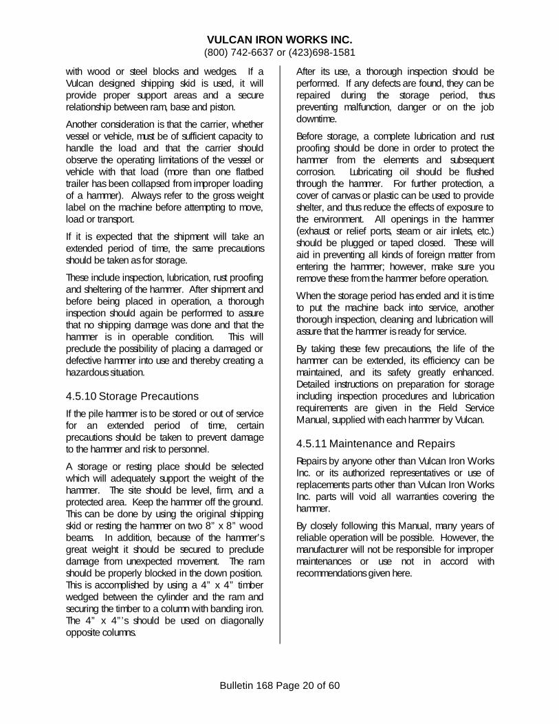
1) All Vulcan studs have an unthreaded portion between the threaded ends (See Figure 5.2.2.2). DO NOT use a pipe wrench to install the stud. Thread damage is possible and the pipe wrench marks or notches will create stress riser points in the stud.
VULCAN IRON WORKS INC. (800) 742-6637 or (423)698-1581
Bulletin 168 Page 25 of 60
Figure 5.2.2.2 Vulcan Stud
2) Install studs by threading a jam nut on the stud. Place a flat washer over the jam nut. Thread a full nut on top of the washer (See Figure 5.2.2.3). The washer prevents the nuts from turning and an impact wrench or hand wrench can be used to install the stud.
Figure 5.2.2.3 Stud Installation
3) Use care not to insert the stud into the thread until it bottoms out. If the stud does bottom out, the stress will be incorrect and failure will be accelerated.
5.3. Cylinder
Refer to the exploded views in the parts section for visual reference.
5.3.1 Cylinder Head Removal
CAUTION
BE SURE ALL STEAM OR AIR LINES HAVE BEEN DISCONNECTED BEFORE ANY REPAIR
OR MAINTENANCE WORK BEGINS.
The cylinder head is fastened by a combination of nuts, bolts and studs. To remove the head:
1) Remove the nuts and jam nuts from the studs.
2) Remove the nuts, and bolts. 3) Lift the cylinder head off the studs. 4) Remove the oil gasket. Be sure no gasket
material remains on the bottom of the cylinder head or top of the cylinder.
5) Disassemble the cylinder head by removing the cross cylinder head bolts.
6) Remove the cotter pins from the sheave pin and drive the sheave pin out.
7) The head sheave bushing should not be removed unless it needs replacement. If the head sheave needs replacement, a new bushing is included with the new sheave. Replace the head sheave when a) wear in the grooving exceeds 1/16” (1.6mm), b) the cable pattern is visible in the sheaves, or c) when the sheaves are loose, indicating a worn bushing.
8) Clean and inspect all items. Replace damaged items. Always use a new gasket for reassembly.
NOTE
If the sheave pin needs to be replaced, insert the new sheave pin with the cotter key in the
existing hole until the key is firmly against the wall of the cylinder head. Then locate
and drill a cotter key hole in the sheave pin. Make the hole the same size as the existing hole and locate it so that both sheave keys are firmly against the walls of the cylinder
head.
5.3.2 Cylinder Replacement
1) Lay the hammer down with the slide bar facing up.
2) Remove the cylinder head and gasket. 3) Remove the slide bar keys, key block, key
block seat and the slide bar. 4) Remove the gland bushing, packing and junk
ring. 5) Install eye bolts in the threaded holes
provided in the piston head. 6) Stand the hammer in the vertical position. 7) Remove the ram keys. 8) Raise the piston until the split bushing clears
the ram. 9) Remove the split bushing, key ring and gland.
VULCAN IRON WORKS INC. (800) 742-6637 or (423)698-1581
Bulletin 168 Page 26 of 60
10) Remove the piston and rod. 11) Remove the cable nuts and washers. 12) Lift the cylinder off the columns. 13) Clean and inspect all items. Replace
damaged or worn parts.
NOTE
When installing new packing gland, do not attempt to tighten the gland to the point of sealing steam or air leakage. A little air or
steam escaping through the packing is acceptable. The oil mixed with the air or
steam will lubricate the packing and piston rod.
5.3.3 Bushing Replacement
Bronze bushings are used in the head sheaves and both steam chest heads. When replacement is required follow the procedures listed below.
1) All bronze bushings are press fit. Due to manufacturing variations, bushings are supplied oversized. The fit of the bushing is obtained by turning the O.D.
2) Mount the bushing in a four (4) jaw chuck, indicating the I.D. for true position. Support the free end with a live center. Alternate method would be to use an arbor between centers.
3) Machine the bushing O.D. to give the proper press fit.
4) After machining, clean the bushing and remove cuttings.
5) Make sure bore receiving the bushing is clean, dry and free of burrs. Press the bushing into the bore without using a lubricant.
5.4 Valve and Steam Chest
5.4.1 Valve Liner Installation or Change
When installing a new valve mechanism the following steps should be observed:
1) With the valve liner in the cylinder and the blind steam chest head removed, place the valve stem and valve into the valve chest with the square end towards the open end of the
valve chest. Rotate the valve and stem until the match marks on both valve and liner are together as shown in Figure 5.4.1.1. (The actual orientation of the valve may vary from the one depicted in the figure). Once this is done, the valve stem is backed away and the trips are installed, first the fixed and then the movable. The valve and stem is then reinserted to the outboard bearing bracket bushing and the movable trips connected to the Vari-Cycle (see Section 5.4.2). The trips should then be as shown in figure 5.4.1.2.
Figure 5.4.1.1 Valve Setting Diagram
Figure 5.4.1.2 Trip Setting Diagram
2) Replace the blind steam chest head, gasket, studs, and nuts. Check all bearings for proper lubrication.
NOTE
Setting the valve properly is essential to insure maximum efficiency.
When replacing the liner it is very important to rotate the liner to the correct angular position. This is accomplished by the dowel pin
VULCAN IRON WORKS INC. (800) 742-6637 or (423)698-1581
Bulletin 168 Page 27 of 60
arrangement shown in Figure 5.4.1.1. The dowel pin holes in both cylinder and liner should be aligned with each other and the dowel pin driven through both.
Should the cylinder require replacing, a new liner is required with the factory set angular position.
5.4.2 Stroke Adjustment for Single Acting Hammers
5.4.2.1 Vari-Cycle
The Vari-Cycle is a mechanical accessory that can be installed on the hammer to allow the operator to attain different levels of rated energy from the hammer. Consult the factory to determine if this option can be installed on your hammer. Most hammers built after 1980 have the Vari-Cycle installed at the factory.
Figure 5.4.2.1.1 Vari-Cycle Mounting
To add the Vari-Cycle:
2) Remove the blind head, the valve, valve stem, trip, dovetail insert, slide bar and trip spacer bushing.
3) Install a three wedge slide bar, fixed trip, movable trip, valve, valve stem and the outboard bearing bracket (if not already on hammer).
4) Remove the four hex-head bolts from the main cylinder pads and bolt on the Vari-Cycle cylinder using the capscrews furnished. Bolt the movable trip to the Vari-Cycle piston rod (See Figure 5.4.2.1).
5) Attach air or steam hose as shown in Figure 5.4.2.2. Hoses are not provided. Although the diagram shows certain hose sizes, there is some flexibility in the sizes which will work.
Air supplied to the trip shifting cylinder head will push the trip out into the short stroke position. Air supplied to the trip shifting cylinder will pull the trip back to the long stroke position.
NOTE
Vulcan does not supply the valve or hose.
Two energy levels are selected, generally, full and one-half rated energy. Any combination of energy pairs are available, from full rated to one-third rated energy.
VULCAN IRON WORKS INC. (800) 742-6637 or (423)698-1581
Bulletin 168 Page 28 of 60
Figure 5.4.2.1.2 Vari-Cycle Piping Schematic
5.4.2.2 Outboard Bearing Bracket
Vulcan Pile Hammers equipped with the Vari-Cycle require an outboard bearing bracket on the open steam chest head. The bracket functions as a guard to protect the slide bar from damage and as an outboard bearing for the extended valve stem (See Figure 5.4.2.1.1).
The bracket must be installed with the outboard bearing directly in line with the open steam chest head bushing. Shims are required, under the bracket foot, to obtain the correct alignment. Shim thickness requirements are stamped on the cylinder on either side of the tongue and groove bracket joint. Do not deviate from the shim sizes specified on the cylinder casting.
A new outboard bracket must be installed whenever the cylinder is replaced.
Figure 5.4.2.2.1 Outboard Bracket
5.4.2.3 Traverse Trip
The traverse trip is an alternative method of using the three wedge Vari-Cycle slide bar with a simpler but more economical mechanism of
VULCAN IRON WORKS INC. (800) 742-6637 or (423)698-1581
Bulletin 168 Page 29 of 60
changing the wedge used in the hammer upstroke. For sizes 505 and 506, the traverse trip is the preferred method of achieving less than full stroke.
5.4.2.3.1 Traverse Trip, Full Stroke Position
Looking at Figure 5.4.2.3.1, the valve mechanism has a fixed and traverse trip that can slide along the valve stem and on the face of the slide bar. The trips are prevented from sliding during operation by insertion of a spacer collar. For full stroke operation, the spacer collar and traverse trip should be positioned as shown in Figure 5.4.2.3.1.
Figure 5.4.2.3.2 Traverse Trip, Short Stroke Position
For short stroke operation, the traverse trip and spacer collar should be reversed from the full stroke position, as shown in Figure 5.4.2.3.2.
To change from one stroke position to another, remove the blind steam chest head and pull the valve stem out just far enough to remove the spacer and traverse trip. Reinsert valve stem with traverse trip and spacer in the desired order.
5.4.3 Slide Bars
Slide bars and/or trips should be replaced if there is more than 1/8” (3mm) wear in either, or when either is bent or broken.
5.4.3.1 Installation
1) Remove the ram pipe plug. 2) Remove old babbitt by melting with a torch.
CAUTION
Babbitt contains lead! Use with caution. Lead has been shown to have the following
potential side effects:
Low levels
• Headache
• Joint and muscle pain
• Abdominal cramping
High levels
• Anemia
• Kidney disease
• Damage to nervous system
Very High Levels
• Seizures - coma - death
• May be reproductive hazard
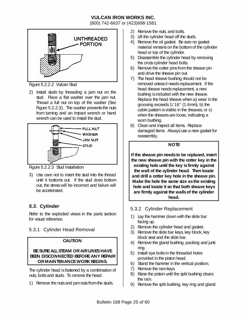
3) Position slide bar, the slide bar end block, slide bar key block seat and slide bar key block (See Figure 5.4.3.1.1).
VULCAN IRON WORKS INC. (800) 742-6637 or (423)698-1581
Bulletin 168 Page 30 of 60
Figure 5.4.3.1.1 Slide Bar Pocket Assembly
4) Pour molten babbitt into the cavity until the babbitt is ¾” (19mm) from top of opening. Use only medium hard babbitt metal Glyco B or equivalent. DO NOT use pure lead.
5) After the babbitt has solidified, install the ram pipe plug.
NOTE
Some hammers have a solid slide bar pocket end in place of a babbitt hole. In this case,
simply perform step (3) and install and tighten the slide bar key.
5.4.3.2. Adjustment
After the slide bar is installed, the slide bar key and key block should be checked to be sure they are tight.
If the slide bar key is loose, shims can be added beneath the slide bar end block.
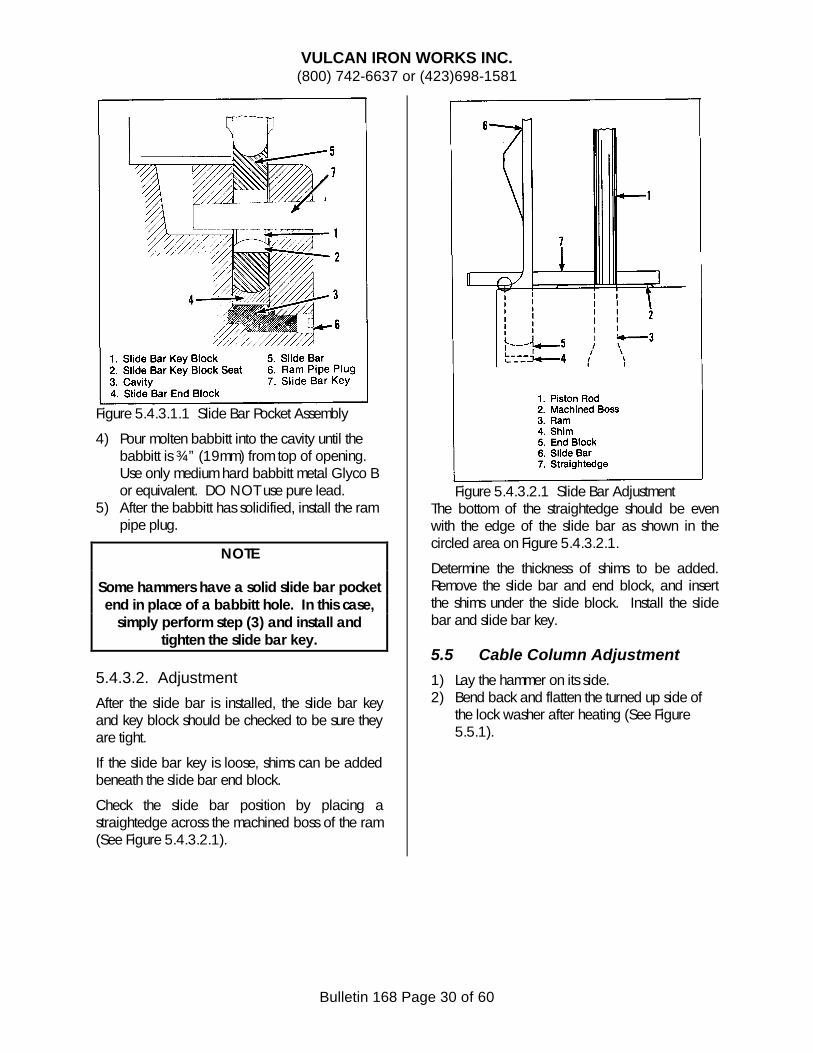
Check the slide bar position by placing a straightedge across the machined boss of the ram (See Figure 5.4.3.2.1).
Figure 5.4.3.2.1 Slide Bar Adjustment
The bottom of the straightedge should be even with the edge of the slide bar as shown in the circled area on Figure 5.4.3.2.1.
Determine the thickness of shims to be added. Remove the slide bar and end block, and insert the shims under the slide block. Install the slide bar and slide bar key.
5.5 Cable Column Adjustment
1) Lay the hammer on its side. 2) Bend back and flatten the turned up side of
the lock washer after heating (See Figure 5.5.1).
VULCAN IRON WORKS INC. (800) 742-6637 or (423)698-1581
Bulletin 168 Page 31 of 60
Figure 5.1.1 Cable Assembly
3) Screw jacking bar into top cable fitting. 4) Place Jacking pedestal over cable nut. 5) Place jack over jacking bar and screw on
jacking bar nut. 6) Jack each cable to 40 U.S. Tons (355 kN).
Alternate across corners.
CAUTION
Make sure that all personnel are clear of the Jack and Pedestal before applying pressure to the jack! This is to prevent injury in event
of missile reaction.
7) Tighten nut using a ½” (13mm) diameter rod 8) After jacking is complete, heat lock washer
tab with torch and bend against flat on cable nut.
9) Remove jacking bar nut, jack, pedestal and jacking bar.
10) Repeat steps 1 through 9 on remaining cables.
5.6 Side Channels (Cylinder and Base) Replacement
1) Use a drill to remove the countersunk head of the channel rivet studs. Make sure that the threads on the cylinder and base are undamaged.
2) Slide the channel toward the cylinder head end of the hammer and remove the channel.
3) Remove the remaining portion of the rivet studs by drilling a hole in the center of the stud. Insert a backing out tool (Ezy-Out®,) and remove the studs.
4) Install the channel by sliding it into the jaws on the hammer. Align the holes in the channel with the stud holes in the cylinder.
5) Insert the channel rivet studs. Torch cut the studs ¾” (19mm) above the channel surface.
6) Heat the exposed portion of the rivet stud with a torch and hot rivet each stud flush with the channel web surface. It may be necessary to hold the channel in place with capscrews while riveting.
7) Heat the two ears which extend beyond the base and cylinder walls and bend them flat against the cylinder or base.
5.7 Ram and Striking Parts
5.7.1 Piston Ring Gaps and Bore Specifications
All Vulcan onshore hammers use a single piece piston and rod with two piston rings. Gap specifications for these are given in Table 5.7.1.1.
VULCAN IRON WORKS INC. (800) 742-6637 or (423)698-1581
Bulletin 168 Page 32 of 60
This should be checked whenever new piston rings are installed or old ones reinstalled.
SI Units (mm) 342.90 345.28 347.66 419.10 421.28 423.66 482.60 484.98 487.36 552.45 554.83 557.21
If the gap on standard piston rings is too large because the bore is larger than the minimum oversize diameter, then standard oversize piston rings can be fitted to the hammer. For hammer with a bore larger than the maximum oversize diameter, a new cylinder is required. These dimensions are given in Table 5.7.1.2.
VULCAN IRON WORKS INC. (800) 742-6637 or (423)698-1581
Bulletin 168 Page 33 of 60
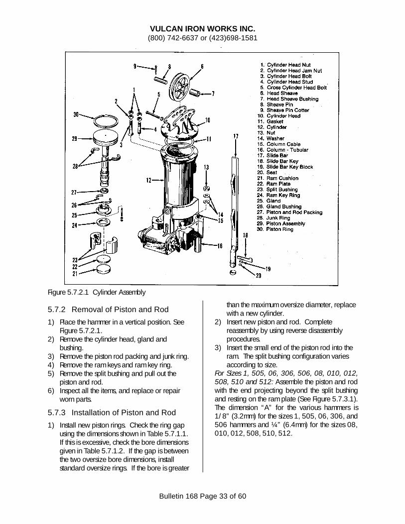
Figure 5.7.2.1 Cylinder Assembly
5.7.2 Removal of Piston and Rod
1) Place the hammer in a vertical position. See Figure 5.7.2.1.
2) Remove the cylinder head, gland and bushing.
3) Remove the piston rod packing and junk ring. 4) Remove the ram keys and ram key ring. 5) Remove the split bushing and pull out the
piston and rod. 6) Inspect all the items, and replace or repair
worn parts.
5.7.3 Installation of Piston and Rod
1) Install new piston rings. Check the ring gap using the dimensions shown in Table 5.7.1.1. If this is excessive, check the bore dimensions given in Table 5.7.1.2. If the gap is between the two oversize bore dimensions, install standard oversize rings. If the bore is greater
than the maximum oversize diameter, replace with a new cylinder.
2) Insert new piston and rod. Complete reassembly by using reverse disassembly procedures.
3) Insert the small end of the piston rod into the ram. The split bushing configuration varies according to size.
For Sizes 1, 505, 06, 306, 506, 08, 010, 012, 508, 510 and 512: Assemble the piston and rod with the end projecting beyond the split bushing and resting on the ram plate (See Figure 5.7.3.1). The dimension “A” for the various hammers is 1/8” (3.2mm) for the sizes 1, 505, 06, 306, and 506 hammers and ¼” (6.4mm) for the sizes 08, 010, 012, 508, 510, 512.
VULCAN IRON WORKS INC. (800) 742-6637 or (423)698-1581
Bulletin 168 Page 34 of 60
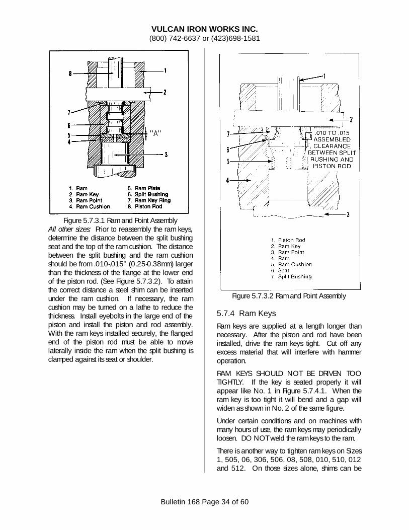
Figure 5.7.3.1 Ram and Point Assembly
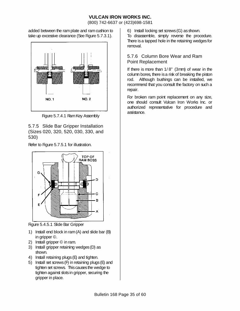
All other sizes: Prior to reassembly the ram keys, determine the distance between the split bushing seat and the top of the ram cushion. The distance between the split bushing and the ram cushion should be from .010-.015” (0.25-0.38mm) larger than the thickness of the flange at the lower end of the piston rod. (See Figure 5.7.3.2). To attain the correct distance a steel shim can be inserted under the ram cushion. If necessary, the ram cushion may be turned on a lathe to reduce the thickness. Install eyebolts in the large end of the piston and install the piston and rod assembly. With the ram keys installed securely, the flanged end of the piston rod must be able to move laterally inside the ram when the split bushing is clamped against its seat or shoulder.
Figure 5.7.3.2 Ram and Point Assembly
5.7.4 Ram Keys
Ram keys are supplied at a length longer than necessary. After the piston and rod have been installed, drive the ram keys tight. Cut off any excess material that will interfere with hammer operation.
RAM KEYS SHOULD NOT BE DRIVEN TOO TIGHTLY. If the key is seated properly it will appear like No. 1 in Figure 5.7.4.1. When the ram key is too tight it will bend and a gap will widen as shown in No. 2 of the same figure.
Under certain conditions and on machines with many hours of use, the ram keys may periodically loosen. DO NOT weld the ram keys to the ram.
There is another way to tighten ram keys on Sizes 1, 505, 06, 306, 506, 08, 508, 010, 510, 012 and 512. On those sizes alone, shims can be
VULCAN IRON WORKS INC. (800) 742-6637 or (423)698-1581
Bulletin 168 Page 35 of 60
added between the ram plate and ram cushion to take up excessive clearance (See Figure 5.7.3.1).
Figure 5.7.4.1 Ram Key Assembly
5.7.5 Slide Bar Gripper Installation (Sizes 020, 320, 520, 030, 330, and 530)
shown. 4) Install retaining plugs (E) and tighten. 5) Install set screws (F) in retaining plugs (E) and
tighten set screws. This causes the wedge to tighten against slots in gripper, securing the gripper in place.
6) Install locking set screws (G) as shown. To disassemble, simply reverse the procedure. There is a tapped hole in the retaining wedges for removal.
5.7.6 Column Bore Wear and Ram Point Replacement
If there is more than 1/8” (3mm) of wear in the column bores, there is a risk of breaking the piston rod. Although bushings can be installed, we recommend that you consult the factory on such a repair.
For broken ram point replacement on any size, one should consult Vulcan Iron Works Inc. or authorized representative for procedure and assistance.
VULCAN IRON WORKS INC. (800) 742-6637 or (423)698-1581
Bulletin 168 Page 36 of 60
5.8 DRIVING ACCESSORIES
The pipe cap is loaded with cushion material as shown in Figure 5.8.1 if it has a standard pot and 5.8.2 if it is fitted with a capblock follower. If the latter is used, in addition to the cabling procedure described in Section 4.1, the hammer must be cabled to the follower and the follower to the pipe cap. Do not use rusted or scrap cable for this application!
Whenever the cushion pot ring is cracked or broken it must be replaced with a repair ring. Consult the factory for this procedure.
Care must be taken when welding adapters of any kind onto pipe caps, since these are for the most part alloy steel castings and require special welding procedures and care.
WARNING
Welding of any kind on hammers should be avoided and, if necessary, only performed
with factory authorized procedures.
Figure 5.8.1 Integral Ring Cushion Pot
Figure 5.8.2 Capblock Follower
VULCAN IRON WORKS INC. (800) 742-6637 or (423)698-1581
Bulletin 168 Page 38 of 60
6.0 TROUBLESHOOTING
HAMMER RUNS TOO SLOW
CAUSE REMEDY Air or steam pressure too low. Check pressure at compressor. Due to line loss, the
pressure at compressor should be greater than the manufacturers required pressure at the hammer. Use air needle gauge to check air hose pressure at the hammer.
Air supply line too long or not proper size. Use specified line size or larger. Supply line from the compressor to the hammer should be only as long as necessary. Eliminate as many bends and elbows in the air or steam line as possible.
Air supply line restricted in some manner. Try new hose. Check throttle valve to see that it opens properly. Eliminate all hose kinks and as many elbows and bends as possible in the supply line. Check for any other kind of restrictions or blockages in the line.
Lack of lubrication. Check oil level in line lubricator and see that lubricator is functioning properly. Check hammer columns for burrs and lubricate columns properly. Check for proper lubrication oil.
Worn or broken piston rings or scored cylinder wall. Check this by allowing enough air to enter the cylinder to hold the ram in about a half-raised position and note whether excessive air is escaping out of exhaust ports at top of cylinder.
Replace piston rings. Be sure rings have required gap. Machine scores from cylinder wall.
Piston rod packing too tight. Loosen packing gland nuts until they are just hand tight against the packing gland. Lock the two nuts against each other to keep them in place. A small amount of steam leakage from the packing gland is not objectionable.
Leakage or using air for other purposes while hammer is running.
Stop leaks and other waste of air while hammer is operating.
Badly worn slide bar wedges or trip. Replace slide bar or trip. Loose cables caused by loose nuts or broken washers. Replace the broken nuts or washers and retighten
cables equally according to our specifications.
VULCAN IRON WORKS INC. (800) 742-6637 or (423)698-1581
Bulletin 168 Page 39 of 60
HAMMER RUNS TOO FAST
CAUSE REMEDY
Excessive air pressure on hard driving indicated by bouncing of hammer on up-stroke.
Slow down by partially closing the throttle valve.
Ram not making full stroke. Check for bent or twisted valve stem. Check valve setting.
EXCESSIVE SLIDE BAR BREAKAGE
CAUSE REMEDY
Slide Bar Key loose. Check slide bar key and key seat for proper fit. Key must be kept tight at all times.
Tie cables loose or unequally tensioned. Tighten tie cables to prescribed tension.
Worn dovetail. Replace dovetail insert.
HAMMER CHANGES SPEEDS WHILE OPERATING
CAUSE REMEDY
Air Compressor not large enough. Use larger size air compressor. Do not use air for other purposes while hammer is operating.
Loose or torn hose lining. Replace with new hose.
Intermittent lubrication caused by defective line lubricator. Replace lubricator.
Loose slide bar. Replace slide bar, slide bar key, or gripper.
Icing. In your air line oiler, dilute your lubricating oil with an equal amount of ethylene glycol.
Pile Rebound This is a normal occurrence in pile driving. Make sure compressor operator maintains desired stroke.
VULCAN IRON WORKS INC. (800) 742-6637 or (423)698-1581
Bulletin 168 Page 40 of 60
HAMMER LEAKS STEAM AT MAIN EXHAUST PORT CONSTANTLY
CAUSE REMEDY
Valve not seating properly. Check to see if valve is broken or scored. Replace with new valve.
Scored or broken steam chest liner. Replace steam chest liner.
HAMMER LEAKS STEAM EXCESSIVELY FROM EXHAUST PORTS AT TOP OF CYLINDER ON UPSTROKE
CAUSE REMEDY
Worn or broken piston rings. Replace piston rings.
Scored cylinder wall. Machine scores out of cylinder wall.
RAM HANGS AND HAMMER STOPS OPERATING
CAUSE REMEDY
Loose or unequally tensioned cables. Retension cables to specified tension.
Rust or burrs on columns. Dress columns to smooth finish.
Piston rings too large and seized up in cylinder. Check ring dimensions and see that they have sufficient gap.
Piston packing too tight. Loosen packing gland nuts until they are just hand tight against packing gland. Lock the two nuts against each other to keep them in place.
Icing In your air line oiler, dilute your lubricating oil with an equal amount of ethylene glycol.
Insufficient lubricant Check column or air/steam line lubricant.
VULCAN IRON WORKS INC. (800) 742-6637 or (423)698-1581
Bulletin 168 Page 41 of 60
CABLE BREAKING
CAUSE REMEDY
Pile running out from under hammer causing ram to strike base.
Shut down hammer at throttle valve.
Unequal tensioning causing one cable to do all of the work.
Keep cables tensioned equally according to our specifications.
Insufficient cushion material allowing ram to strike base. Top of top plate should not be lower than 3” (76mm) below top of cushion pot.
VULCAN IRON WORKS INC. (800) 742-6637 or (423)698-1581
Bulletin 168 Page 42 of 60
7.0 MAJOR OVERHAUL Under average use the Vulcan pile hammer should be completely overhauled after every 400 to 500 hours of use.
Major overhaul should be accomplished by an authorized Vulcan Iron Works distributor. If the location of distributor is not known, contact
Vulcan Iron Works Inc. P.O. Box 5402
2909 Riverside Drive Chattanooga, TN 37406
(423) 698-1581 Toll Free (800) 742-6637
Telecopier (423) 698-1587 The necessary information will be supplied.
If any disassembly work is done on site, the hammer should be completely cleaned and then disassembled, all parts should be cleaned and carefully inspected. Using this manual, check all parts to see if there is any excessive wear or damage and to replace those parts which are no
longer usable. The most important consideration in any overhauling procedure is the cleanliness of the work and environment. This is true in both disassembly and reassembly. AVOID DIRT, GRIT, WELDING SLAG, AND ALL FOREIGN MATTER, AND PROPERLY LUBRICATE AND SEAT THE PARTS AS THEY ARE REASSEMBLED.
After reassembly or overhaul, the hammer should be examined carefully and lubricated according to the lube information in this manual. Follow warming procedures prior to starting driving operations.
CAUTION
ALWAYS USE GENUINE VULCAN REPLACEMENT PARTS WHICH ARE
AVAILABLE FROM DISTRIBUTORS OF VULCAN IRON WORKS INC.
8.0 STORAGE When the hammer is placed in storage or will not be used for some time, cover the steam or air inlet, exhaust outlet and relief parts. Take precautions to prevent dirt from entering the steam chest and cylinder.
Protect the columns, piston and rod, and the slide bar by wrapping with cloth. Tie the cloth with wire and soak it with oil.
The hammer should be stored on its side and in a protected area. Keep the hammer off the ground and covered if possible.
Insert oil soaked rags into the exhaust port of the valve chest.
Pour a quart of oil in the air intake and seal the intake with waterproof tape.
On single acting hammers, pour a quart of oil into the exhaust port at the top of the cylinder. Seal the port with waterproof tape.
On differential acting hammers, insert oil soaked rags into the lower cylinder around the piston rod.
Refer to “Storage Precautions” in the Vulcan User’s Guide.
VULCAN IRON WORKS INC. (800) 742-6637 or (423)698-1581
Bulletin 168 Page 43 of 60
9.0 SHIPPING
DO’S DONT’S
Always secure lifting slings to the hammer, NOT TO THE SKID.
Never pull or drag the hammer with any line fastened to the skid.
Always attach slings to top of Cylinder (A) and Base (B) as shown.
Never attach slings to any of the four columns of the hammer.
Always secure sling behind channel, not over, if hammer has channels.
Never attach slings to ram point of hammer.
Always make sling angle (E) less than 60°. Never attach slings to hammer at or near slide bar location.
Always check hammer weight to determine sling size. Never attach sling to piston rod of hammer.
Always place forks at approximate locations C & D for fork truck handling.
Never place forks between hammer and skid.
Always secure the line to the hammer.
VULCAN IRON WORKS INC. (800) 742-6637 or (423)698-1581
Bulletin 168 Page 45 of 60
10.0. PARTS LIST
10.1 General Notes
Refer to the parts drawing in this section of the manual that identifies the part or assembly with the key number and a line pointing to the part or assembly. Refer to the name of the part or assembly as given in this manual. Use this name and part number in ordering parts. PARTS ORDERS SHOULD INCLUDE THE FOLLOWING INFORMATION.
1) Size and Serial Number of the Hammer. 2) Part Number and Name. Do not use the key number. 3) Quantity required. 4) Specific Shipping Instructions. 5) Purchase order number, if any. Concerning the serial numbers, beginning in the late 1960’s Vulcan adopted a system of serial numbers that gave the year of the hammer’s manufacture without having to consult the factory. All of this type of serial number is in the format of
XX-YYYY
where “XX” represents the year code in two letters; they translate into the last two digits of the year as follows:
Letter Digit A 1 B 2 C 3 D 4 E 5 F 6 G 7 H 8 I 9 J 0
Thus, the serial number “GF” translates into “76”, thus the hammer was made in 1976.
The “YYYY” is a sequential number assigned to the particular hammer.
For years of manufacture with strictly numerical serial numbers, please consult the factory.
VULCAN IRON WORKS INC. (800) 742-6637 or (423)698-1581