Page 1
VW in-line four cylinder engines into T3 Transporter - Gary Dawson
Engine Choice
1.8 litre engine from MkII Golf GTi, Passat, etc (PB code).
Often suggested and used for this conversion.
Advantages – because it was effectively a factory conversion of the earlier carburettor engine cars,
the wiring for the Digifant injection and ignition system is in its own separate loom with just a very
few wires to connect to live, ignition live, earth, etc.
Disadvantages - Age – the last of these is from about 1989 although there are a lot of them about
still and parts appear to be readily available. Main issue is that the inlet manifold clashes with left
side inner wing. In a normal Bus it requires a fairly severe denting or reworking of the inner wing. In
a syncro (because the engine and transmission sit 50mm lower) it would mean cutting away ¾ of the
chassis rail just below the shock absorber mount. Not something I would suggest is acceptable.
2 litre engine from early MkIII Golf GTi, Passat, etc (2E code)
Advantages – fits without clashing with the inner wing. Still uses a modified Digifant system although
the wiring is now combined with the engine gauge sensors, lights etc. It is apparently possible to use
the PB Digifant system on a 2E engine which would perhaps be the simplest way to go.
Disadvantages – 2E engines are sort after by the Golf aficionados who use the blocks to upgrade the
PB engines.
2 litre engine from late MkIII Golf GTi, Passat, etc (AGG code)
Advantages – again it fits without clashing with
the inner wing. The inlet manifold is much smaller
than that on the 2E, giving more space around the
front end of it (in the corner of the engine bay).
AGG has slightly more power and slightly better
torque at lower revs. What are the figures?
Disadvantages – different (Bosch Simos) injection
and ignition system with the wiring fully
integrated into a single loom for the front end of
the car. (Two thirds of this loom is not needed for
the engine and needs sorting out.) If the car had
air conditioning, the alternator and air con pump sit on a large aluminium mounting casting that
bolts over the water pump. This puts the
alternator too high to allow the engine deck lid
to close and uses two belts (one ‘V’ and one
ribbed) to drive everything. These need to be
simplified down to a single belt unless you
have air con and or power steering in your
Bus. Therefore, make sure you get an engine
without air con when the alternator mount is
much smaller and simpler and puts the
alternator much lower. This also gives
clearance for the JX dipstick to be retained in
its normal location.
Page 2
Buying your engine
When you select your engine you are looking for a lot of bits beside the block.
engine with all ancillaries – if your van does not have aircon or PAS, try to find a car without them
too. (The alternator and belts arrangement is quite different. Aircon alternator is too high to fit
under T25 engine hatch.
Complete engine bay wiring loom (right through bulkhead to fuse box)
Relays - numbers 30 & 167 (for fuel pump, ignition coil and ECU.)
Fuel tank vent valve (emissions) not sure if this is needed but puts up an ecu fault if not connected.
Valve needs electrical connection but not pipework) Usually mounted somewhere behind drivers
headlight/air filter. Mine is a cylinder about 2” diameter & 4” long with a bracket across for
mounting.
Air intake hose
MAF unit and intake temperature sensor from air filter
ECU & mounting plate
Keys (they have the immobiliser transponder)
Immobiliser ‘aerial’ (fits around ignition/steering lock) will also clip onto T25 lock barrel. Follow
leads from this to find the immobiliser box (about 3x2x1” black box with 2(?) small multiplug
connectors.
Lambda probe from exhaust pipe complete with lead
Exhaust manifold (and front pipe may be useful)
Ignition coil - 2” cube?
I would look for an engine that is still in the car and running and which you could perhaps help to
remove so that you see how it comes apart/goes together. You can then also ensure that you get all
the bits (above) that you need.
Bits not needed include: starter, flywheel, clutch, engine mounts, air filter, most of the hoses (use JX
hose layout except pipe from pump to middle of cylinder head).
AGG
Mechanical fitting (most of this applies to all types)
Mechanically these engines are all very similar to the JX diesel engine although the blocks are slightly
(19mm?) taller. If your Bus was a JX turbo-diesel variant then this is the simplest starting point. If not
you will need to acquire all the mechanical mounting parts (including welded-in engine carrier bar
mounts) before you start.
See the section below about throttle cable linkage and consider removing & drilling the inlet
manifold at this stage. Prepare your engine by removing any Golf mounting parts and any heatshield
from the exhaust manifold. (This otherwise clashes with the JX engine mount.) Offer up the JX
mounts to identify the threaded holes in the block that you need to use to fit them. Clean out & re-
tap the threads in these holes to remove ten to twenty years of rust and dirt. Fit the mounts using
the bolts from the JX engine. Suspend engine, drain oil and remove the sump and oil pump.
The car oil pump is similar to the JX one but has two significant differences. Firstly, the drive shaft is
about 15mm shorter (so the JX one won’t fit properly into the block) and the oil pick-up arm is quite
different. To get around this you need to use the JX pick-up arm on the car pump body.
Page 3
Knock out the car dipstick tube. Carefully drill it out to clear the JX dipstick tube from the bottom
end to just past the flange (50mm or so depth). Cut the pipe off just above the flange which sits
against the outside of the engine casting and tap it gently back into the engine. Once the engine is
fully fitted the JX dipstick should slide through this guide tube to sit in almost the original position.
Check that it does fit at this stage but leave it out of the way for now. Refit the sump and bolt it up
loosely at this stage. If it was a turbo-diesel sump, fit a screw plug to block the turbo oil return port.
Remove car clutch, flywheel and engine back plate. Fit JX back plate and flywheel using new stretch
bolts. Check depth of crank shaft centre drilling to confirm it is sufficient for the gearbox input shaft.
This is easiest if you have the JX engine to hand for comparison. Clean out the drilling and fit a JX
spigot bearing and then the JX clutch.
Change the water pipe union on the back of the cylinder head (the clutch end) to the JX one. This
connects the heater pipe and houses the temperature gauge sender unit. At the back of cylinder
head two 8mm water hoses, running to throttle body, are clipped to a metal bracket. I removed this
bracket, modified it and bolted it to the engine lifting eye before refitting the plastic clip. This keeps
the hoses out of the way of the junction box in the back of the engine bay.
Install the engine and lastly tighten the bolts from the gearbox into the sump carefully together with
those holding the sump to the block, ensuring the sump is square and not stressed.
Throttle linkage
The car throttle cable outer is retained by an angle bracket bolted to the top of the inlet manifold.
There is a single bolt into a tapped hole and a stamped peg in the bracket which engages with a blind
hole in the manifold. Drill out the blind hole and tap it at M6 for a second bolt. The casting is much
thinner here and the hole will go right through. As this will leave swarf in the inlet manifold to be
eaten by the engine when you start it, you may want to do this before you fit the engine and remove
the manifold first. Once in the Bus, to remove the inlet manifold, the engine needs to be lifted off
the rubber mounts and swung to the right to give enough clearance.
Use a length of 25x3mm steel strip about
100mm long and drill one end to suit the two
tapped holes and the other to take a single bolt
and the stamped peg. This moves the cable
outer retainer forward by about 75mm to a
point where the JX cable can reach and it also
makes space for connecting the JX and car
cables together.
To do this, remove the ball from the joint on the
end of the JX cable and drill a clearance hole
through the ball socket for an M8 bolt. Drill a
3mm hole through the bolt close under the
head (allowing for the thickness of a washer
above it). Use the first 300mm or so of the car
inner cable (plastic coated steel wire), fit it to
the throttle spindle pulley and pass the cut off
end through the 3mm hole and bolt it to JX
Page 4
cable end. Slide the car cable through the bolt to adjust tension. Get an assistant to depress the
throttle pedal and check for full travel at the throttle body. You may need to trim the stop on the
base of the pedal or remove some trim from below it.
Electrical
The remote Simos components you need to fit are:
ECU – needs to be protected from too much heat – right hand rear light void, behind
battery?
Coil unit – within HT lead reach of the distributor – on left side wheel arch?
Air mass meter or MAF – on/near air filter to measure air flow
Air intake temperature sensor – in air filter to measure ambient air temperature
Activated charcoal solenoid – part of fuel tank vapour control measures which aren’t needed.
However, the ECU will be expecting to sense the solenoid so I have included it.
Relays and fuses for fuel pump, ignition coil and ECU. Recover relays (numbers 30 & 167)
from donor car and purchase the correct relay mounting/connector blocks to suit. If using
the diesel fuel cut-off lead to supply your ‘ignition live’ feed to the system, this is a much
lighter cable than the Simos ignition coil feed,
therefore include a relay for this too. Use the JX
fuel cut-off cable as the supply to switch all
three relays (pin 86). Connect to ‘P1’ live point
beside relays in the engine compartment
junction box (next to glow plug relay) for power
to be switched by all relays. I got an enclosure
(from Maplins) to house three relays and four
fuses. I mounted this on the wheel box to the
left of the junction box.
Mount coil to left side inner wing above inlet manifold.
Use one bolt as an earth point. There are several JX earth terminals here and others will come from
the AGG loom. Make sure it is a good clean connection to bare metal. I understand that the earthing
points are critical to the electronic system!
Mount the ECU in the space behind the
battery and RH rear light by brackets to
underside of floor. It is said to be
reasonably tolerant of dampness but less
so of high temperatures. This location has
an airflow down the snorkel trunking from
the side vent.
The car’s 90 amp Valeo alternator has a
‘W’ terminal ready for rev counter feed
although it is not used in the Golf. It is in a
side mounted two-pin socket together with
the D+ warning light connection. Look for
the D+ & W symbols in the narrow gap
between the socket and the alternator body. Discard the existing plug with the D+ wire unless you
are able to withdraw the unused pin to connect to. Otherwise, salvage the correct 2 pin plug with
two wires attached from the discarded loom (they come with a variety of different lug/key patterns
to prevent wrong connections) and connect it to the D+ (warning light) and rev counter wires in JX
loom.
Page 5
The air mass meter, the intake temperature sensor and the charcoal filter solenoid all fit in the area
of the air filter. In order to re-use the Bus snorkel intake (especially if it is a syncro and likely to be
wading at all) fit the filter in behind the left side rear lights. See Induction Tract section below for
details of what I have done.
Wiring of Simos system
Wiring Loom
This is probably going to be the biggest challenge to most of us doing this conversion. To do it
successfully you will need a multi-meter to check wiring continuity and I would recommend
soldering and heat-shrink protecting all new connections.
The car wiring loom contains many more cables than we need so it has to be split open and cables
cut out. Start from the ECU 68pin connector and work along the loom until there is a branch. (There
may be a small sensor with a two pin connector mounted on the side of the ECU and branching into
the loom. This is the air temperature sensor for the air con system and can be ignored or cut off.)
From the next branch you will need to start cutting away the black insulation tape and protective
coverings. I used wire bag ties to keep everything together in neat order after this.
Use the table in the appendix showing the ECU T68 connections to work out which wires and
connectors you need to keep and which must be cut out. I found it very difficult to start cutting the
first pieces out but soon got into the swing of it. You will be removing about 60 or 70% of the loom!
I thought early on that I would re-route the JX sensor wiring from the engine through the T28a plug
at the back of the block in order to keep it all tidy. However, I found that the T25 sensor wiring had
aged badly and needed replacing from the point where it exits the stiff tube sleeving along the back
of the engine bay. In the end I re-ran these as standard, direct to the sensors. This applies to the two
oil pressure sensors, the coolant temperature gauge sender and the water pump run on switch. All
of these need to be the JX items whereas the second water temperature sensor in the flange on the
side of the cylinder head needs to be the AGG item. This is a dual function sensor and only one pair
of terminals needs wiring to give a signal to the ECU. I have ended up with a few insulated terminals
on the unused wires dangling at the back of the engine.
Cut away a short section of insulation from the heavy lead to the blade terminal on the JX starter
solenoid and solder on a short branch cable and female spade terminal to provide the ‘cranking’
signal to ECU (T68/32).
The MkIII Golf has an immobiliser built into the electronics. I have been told that it is possible to get
the ECU re-programmed to work without the immobiliser. However, I felt it better to keep it and
improve the security of the vehicle. There is a small black box, about 80x50x20mm under the dash of
the car and an aerial ring, fitted around the ignition key switch, connected to it. The key itself
contains a transponder chip. The aerial ring will fit directly onto
the key switch of the Transporter but will require the steering
column shroud to be cut away to provide clearance. Having the
Golf key on the Transporter key ring should be sufficiently
close to operate the system although I have managed to fit the
T3 key blade into the Golf plastic key cover complete with the
transponder chip. The black box needs 12v (ignition live) and
Page 6
earth connections plus the grey/white wire to the ECU (T68/43). This same grey/white wire also
connects to the VAG.com (diagnostics) connector together with 12v & earth.
I have set up the loom to run just
below engine lid around back of
engine bay. I have used sticky pads
and cable ties to mount it and in two
places at the back of the engine
there are small slots in a flange of
the bodywork through which small
cable ties can be fed directly. Use
non-adhesive loom tape to wrap all
the wires together again, once you
are sure everything is working
properly – ie you have run the van
for a few days at least. You can also
re-use some of the split tubing wraps
from the original donor loom to
provide added protection.
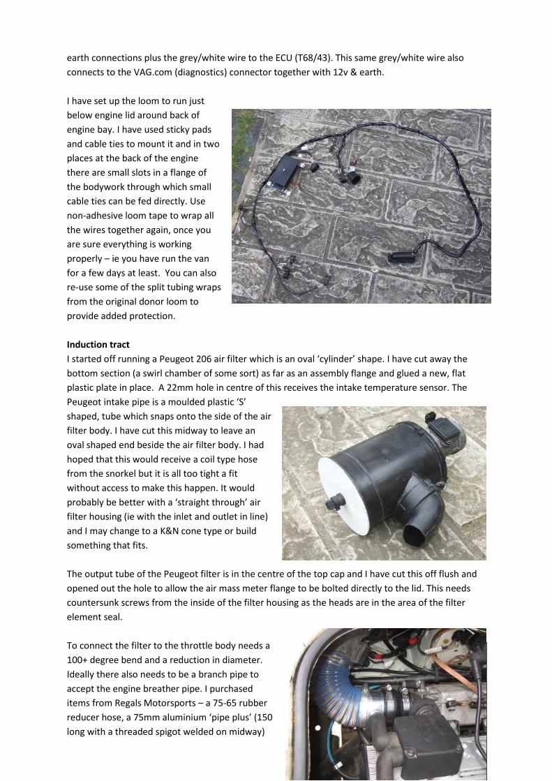
Induction tract
I started off running a Peugeot 206 air filter which is an oval ‘cylinder’ shape. I have cut away the
bottom section (a swirl chamber of some sort) as far as an assembly flange and glued a new, flat
plastic plate in place. A 22mm hole in centre of this receives the intake temperature sensor. The
Peugeot intake pipe is a moulded plastic ‘S’
shaped, tube which snaps onto the side of the air
filter body. I have cut this midway to leave an
oval shaped end beside the air filter body. I had
hoped that this would receive a coil type hose
from the snorkel but it is all too tight a fit
without access to make this happen. It would
probably be better with a ‘straight through’ air
filter housing (ie with the inlet and outlet in line)
and I may change to a K&N cone type or build
something that fits.
The output tube of the Peugeot filter is in the centre of the top cap and I have cut this off flush and
opened out the hole to allow the air mass meter flange to be bolted directly to the lid. This needs
countersunk screws from the inside of the filter housing as the heads are in the area of the filter
element seal.
To connect the filter to the throttle body needs a
100+ degree bend and a reduction in diameter.
Ideally there also needs to be a branch pipe to
accept the engine breather pipe. I purchased
items from Regals Motorsports – a 75-65 rubber
reducer hose, a 75mm aluminium ‘pipe plus’ (150
long with a threaded spigot welded on midway)
Page 7
and 75mm coil hose. I cut the ‘pipe plus’ down to minimum length (20mm either side of spigot) to
accept the adaptor and coil hose. I cut the breather hose spigot from the original AGG induction pipe
and found that it fitted tightly over the aluminium pipe spigot. With the reducer fitted between the
‘pipe plus’ and the throttle body, the branch is also in exactly the right place for the breather pipe.
You will need to squeeze a short length of the coil hose into the tightest possible 100 degree bend to
fit between throttle body & air mass meter. With four large jubilee clips holding everything together
it all fits nicely in place.
There is a tube fixed in the blank end of the inlet manifold to take the vacuum hose for the brake
servo. Don’t forget to fit a non-return valve in the servo vacuum line (the diesel’s pumped system
doesn’t need one). There is another tube out of the throttle body (I think this is part of the charcoal
filter circuit and not needed) which needs to be blocked off.
Cooling
On the side of the cylinder head is a plastic flange which connects two or three water hoses and
houses one or more temperature sensors. We need to keep the AGG (4 wire) twin function sensor
and retain one side for the ECU signal. We also need the JX temperature switch for the water pump
run-on relay and a small hose connection for the throttle body water supply.
Of the many different flange types I had seen,
the MkII Golf GTi (PB) version seemed to be the
best fit. It has the side hose in the right place for
the AGG water pump hose, two sensor sockets
and a 16mm spigot pointing towards the base of
the distributor. Ideally it would have an 8mm
spigot. Anyway, a short length of 16mm hose and
an adaptor can sweep around the distributor and
connect to the throttle body 8mm hose.
These plastic flanges are apparently prone to
cracking so check it carefully. Mine was cracked between the sensor sockets and I ended up buying
as new one (£15 with all the ‘O’ rings). I have since identified that the flange from a MkIII Vento
1.8/2.0 litre GTi has the two sensor mounts and the 8mm branch that is needed.
The AGG throttle body has a water heater unit to prevent frosting in cold weather. There are two
8mm hoses – one to cylinder head flange connection mentioned above & the return which, in the
Golf goes to the top of the pressure bottle. In the T3 that connection has to be used for the hose to
the expansion bottle and, because of the pressure cap, there would in any case be no flow through
the throttle body hoses. I have fitted a Tee piece in place of the straight connector where the T3
heater return hose comes back to the engine bay below the pressure bottle. The throttle body hoses
are 8mm diameter but the connection points are both 16mm. Finding the right size adaptors to
change to 16mm was a problem. The connections are currently made by inserting 8mm connector
into the smaller pipe and clamping the larger pipe over the top. I am not particularly happy with this
and will need to keep an eye on it.
I retained the AGG hose from the flange on the side of the cylinder head to the water pump but
reversed the plastic three-way elbow and then blocked the unwanted connection (which used to go
to the oil cooler in the car). All other hoses are reconnected as per the JX set-up.
Page 8
You need to have the engine running to properly fill the water system but quite a lot can be got in
with care and taking time. It will just have to be checked and topped up once it is running. I initially
used just water until I was sure there were no leaks (I did find a couple of loose hose clips!) Don’t
forget to drain it and add the anti-freeze.
Exhaust
On a German website I have seen that some
people make up a 2 into 1 adaptor from the
exhaust manifold flange to the position of the JX
turbo outlet flange and then use a complete JX
exhaust. This is obviously tempting if you have a
good system left over from your old diesel.
However, I have also been told that this can be
quite noisy, particularly outside the vehicle. Such
an adaptor has become available from Germany
via the ‘2E im VW Bus’ website.
An alternative is to use a waterboxer silencer and fabricate mounts to go between the JX exhaust
mountings and the WBX silencer cradle brackets. I acquired the water boxer silencer cradle brackets
and straps together with a nearly-new silencer. I decided not to retain the rubber units from the
diesel silencer mounts but have fitted the
cradles direct to the mounting points as they
are on the water boxers. The mountings are on
the nearside engine mounting arm, using a strip
of 5mm steel to set the cradle about 50mm
lower, and on the cranked plate which bolts to
the sump on the offside. I have managed to get
the silencer well up out of harms way with just
enough clearance around and above it. I did
need to grind just a fraction of clearance from
the syncro sump guard for the cradles. I got a
front pipe made up to fit from the manifold to the silencer by my local stainless steel exhaust centre.
A threaded boss was welded into this pipe for the lambda probe and a short flexible section to allow
a degree of movement and to reduce the risk of cracking. On a syncro you also need to ensure that
the pipe is tucked well up but does not interfere with the sump guard. The advantage of this system
is that it produces a very subdued exhaust note – remarkably different from the deafening JX/AAZ
sound!
Fuel
The T3 2.1 DJ Digifant injection system appears to
run at a lower fuel pressure so its pump will not
be adequate for the GTi engines. The AGG cars
use an ‘in-tank’ submerged pump which is not
easily re-used in the T3. I have used a Golf MkII
pump unit which also has a reservoir and filter
mount and this should deal with any problem of
surge, or fuel starvation, under hard acceleration.
Page 9
It is obviously good practice to fit a new filter. I have mounted this package ahead of the LH rear
trailing arm mounting, fixing it up to the floor. As it is in a syncro I have since fitted a protection plate
below it to avoid ground contact when off-road.
Thoroughly drain the fuel tank! I started by syphoning fuel through the draw pipe to the diesel filter
and then pulled this hose back from above the
syncro tank and down to the ground on the
nearside so that the last cupfuls could flow out. Re-
direct both hoses to the new pump location as feed
to reservoir and final spill-return. Pass all the hoses
through the hole in chassis cross member along
with existing cables etc. Two other connections
from the pump go to the fuel injection rail at the
front of the engine (cam belt end). This fuel rail is
made of two concentric tubes with a pressure
regulated connection. The outer one is fed from
the pump and connects to the injectors. Over pressure here is relieved to the inner pipe and returns
to the fuel pump reservoir. I ran these lengths in plastic pipe salvaged from the MkII Golf and fitted
short lengths of high pressure rubber fuel hose to make the connections. The plastic pipe has brass
inserts in each end to prevent crushing by the hose clips.
Testing
I was concerned that any faults with my wiring could damage the ECU so carried out many continuity
circuit tests before connecting the battery and ECU. All the relay functions were tested and
confirmed and no errors were found. I also put a few litres of petrol (remember it’s not diesel any
more!!) in the tank and checked that the fuel relay and pump operated as expected. This also
allowed checks to be made on the integrity of the fuel line connections. All seemed OK until I looked
under the vehicle at the pump itself. Fuel was seeping very gradually from around the pump at the
point where it mounts into the reservoir. Checks via the Club GTi forum and with the local VW
dealers proved that parts are still available. I clamped off the hoses and carefully drained down the
system (remember it can sustain high pressure over a prolonged period) then tried to remove the
pump from the housing. However, after 21 years the self tapping screws were well rusted into the
housing and, being cross head screws, they don’t afford much purchase. I ended up carefully sawing
through each of the three lugs of the retaining ring so that the pump could be removed and then
loosening the screws with pliers. When they were out it was obvious the rust expansion had also
split the housing. This required a new housing, together with, retaining ring, screws and seal.
The new O-ring seal is a tight fit into the housing but has to get down beyond a shoulder where the
diameter reduces. The seal needs to be well lubricated and I used white spray grease. There is a
strainer which goes in first, then the seal goes on the ‘petrol’ end of the pump and up against the
rounded shoulder. The pump is then inserted into the housing and strainer until the O-ring meets
the shoulder. I then kept pressure on the pump whilst gently levering the seal inwards with a blunt
old screwdriver. When I got all the way around, the seal popped into place but left the pump sitting
high. However, by fitting the retainer ring and screws and working the screws in evenly, the pump
pulled down.
Page 10
Starting
After the exhaust was built I fitted the lambda probe, temporarily wired the immobiliser and tried
starting it. Given all the difficulty in sorting out the wiring and that there are four or so wires that
originally went to the dash area which remain unconnected I feared the worst. However, it fired on
the first compression and ran smoothly. Once the oil pressure came up the engine sounded very
good and the exhaust note is pleasant, too.
Next thing was to get water in (no antifreeze at this stage) to check the system and find the loose
hose clips etc. As it filled up I discovered a leak from the clutch end of the engine. Fortunately,
investigation revealed the heater hose on the end of the cylinder head had not been clamped up!
Running
The first drive up our short private road (tax & MOT had run out while the work was ongoing)
showed it pulls well and sounds very subdued – just how I wanted it. Since then my early driving
(after getting the MOT) has all been positive. It is so long since I drove the bus I have had to get used
to it again as well as learning about the engine’s characteristics. As the front end had had some new
suspension and steering components I got the wheel alignment adjusted. After this, the vehicle felt
so much more ‘settled’ on the road and I began to realise just why I had put so much effort into the
conversion – the joy of driving it is coming back to me.
Analysing
Shortly after getting back on the road I was able to get a vag.com computer connected to the ECU.
This showed a couple of existing fault codes to do with the lambda sensor (possibly because I had
switched the ignition on before connecting up the lambda) and a ‘road speed sensor’. We were also
able to adjust the rev counter to get the best match to engine speed. (There is a sticker on the back
of the rev counter which covers a hole through which a small screwdriver can be used to adjust a
potentiometer.)
There is a mounting point on the Transporter speedometer where a cover piece can be snapped off
and a speed sensor (part no: 321 907 344) can be mounted.
First Drives
After two weeks of driving the vehicle on short runs locally and gaining confidence we went off on a
ten day, 450 mile camping trip. The vehicle performed faultlessly during this trip and the first refill
after 250 miles gave a fuel consumption figure of roughly 25mpg. The only issue we had was that the
bolts on either end of the silencer worked loose and one fell out. I probably hadn’t tightened them
fully.
Next Steps
Page 11
It seems that most people fitting non-standard engines recommend fitting oil pressure and
temperature gauges so that a check can be made on how the engine is performing in its new
environment. The oil filter mounting on the AGG engine has three tapping points. One takes the high
pressure sensor for the oil warning light, a second takes an oil temperature sender for the car and
the third is blanked off. This means that two new sensors can be fitted without needing Tee-piece
adaptors.
To install these I have included wires in a new loom running to the dash area. This has a grey/white
wire for the immobiliser, a yellow/black for the oil pressure gauge, a green/black for the oil
temperature gauge and blue/white for the road speed signal. I have also included two spare wires
for future needs. I have brought the wires from the engine sensors through the T28 connector (using
the AGG wires already in place) and those from the loom to a single point and used a 6-way plug &
socket connector to join them to the new loom.
Update
The immobiliser box and VAG-com connector have all
been moved to the cab and fitted under the dash.
The transponder aerial ring just clips over the T3 lock
although the shroud needs trimming back a bit to
clear it. I managed to pull the Golf key blade from the
plastic cap and trimmed the T3 key to fit in its place. I
now have a single key for all the doors, ignition etc
and it works the immobiliser, too. I also have a second key coded as a spare.
I have mounted the oil gauges in a separate pod on top of the standard instrument housing. The
sensors came with 1/8” NPT threads but these are very close to the M10x1 threads provided by VW
in the oil filter housing. They are so close, in fact, that they can be screwed straight in and only bind
slightly after several turns. They have not leaked in use. Having the oil pressure gauge in place led to
some concern because it indicated 90psi at anything other than hot idle revs. All figures published
suggest around 40psi (2-3bar) when hot at 2,000rpm or so. Eventually, my local VW dealer found a
figure of 7 bar maximum safe pressure under any conditions. Since 90psi is only 6 bar I stopped
worrying.
I found the LED lighting in the gauges was much too bright despite the standard T3 brightness
adjustment. I have now wired the two lamps in series so that they are effectively running 6 volts and
added a couple of resistors to get them down to sensible brightness level.
I was in two minds about fitting a road speed sensor, given that
the engine was running very well without it. The T3 cruise control
sensor mentioned earlier is physically different to the Golf sensor
(two wires instead of three to start with) so may not provide the
correct signal. However, since one became available I did fit it and
the first trip afterwards (Vanfest 2010) showed a marked
improvement in fuel consumption – up from 25/26 to 29.5mpg!
Other things will have been different as well I’m sure but if the
Page 12
ECU falls back on a pre-configured setting in the absence of the signal then the presence of a signal
could well make a significant difference like this. In truth this improved fuel consumption has not
been sustained. My long trips are usually done at 70+mph on the motorways and it then returns
around 25mpg. It's just goes too eagerly to drive it slowly!
Round Up
It took me a long while to complete this conversion due to the need for considerable research.
However, I have found it to be very worthwhile. The engine has more than enough power and
torque, appears to return very good fuel figures and is especially quiet. I have still got a few bits to
sort out and, since I am getting the vehicle back on the road, there are issues apart from the engine
(CV joints, bushes, bodywork, etc) which also need attention. At least now I can drive it and enjoy
doing so. Certainly I would recommend this conversion.
I reckon it cost me around £750. However, there are a number of ways it could be done cheaper
(you might get an MOT failure car for less than the engine cost me, for instance and sell on parts you
don't need). I also paid £200 for the stainless exhaust where many people would weld up their own
system.
Information sources
Websites
http://www.brick-yard.co.uk/forum/t3-petrol-engine-upgrades_forum22_page1.html
http://2e-im.vw-bus.net/ or
(http://ph.babelfish.yahoo.com/translate_url?doit=done&tt=url&intl=1&fr=bf-
home&trurl=http%3A%2F%2F2e-im.vw-bus.net%2F&lp=de_en&btnTrUrl=Translate)
http://www.t3-bullibus.de/ or
(Translation result for http://www.t3-bullibus.de/index.php/mein-motorumbau/kabelsalat.htm)l
Appendices
ECU T68 connections
Engine T28a connections
Relay wiring
Loom layout
JX engine loom
Hose parts from Regals Motorsports (via ebay webshop)
Gauges from McGill Motorsports (via ebay webshop)
Update 18-07-2012
Page 13
Air Filter – Take Two
One area where I remained less than happy was the air filter. I had used a Peugeot 205 air filter
which fits in behind the LHS tail-lights but does not easily accommodate a connection to the snorkel
intake. (the intake to the filter is a very wide flat oval shape at a position which won't allow a hose to
get to the bottom of the snorkel.) This is particularly important to me as my VW is a syncro and
therefore likely to be used off-road.
My thinking was that the ideal solution would be a straight-through cylinder shape with the air mass
meter bolted to the end plate. I have found this one (http://www.ebay.co.uk/itm/Enclosed-Cold-Air-
Intake-Filter-Box-Universal-Mirror-Silver-TXA-Plus-Bracket-
/380389925241?pt=UK_CarsParts_Vehicles_CarParts_SM&hash=item589101a179) which looks to be
of a suitable size. It contains the 'standard' oiled-cotton conical filter.
Even though the body is only 200mm long by the time you add the AFM one end and a hose bend to
the other, it is too long to fit comfortably into
the wheel arch/ rear light cavity. I hadn't
expected the filter element to be built onto
the end plate so I had to re-think how I would
mount the Hitachi AFM to the end flange. I
made up this ring from some 3mm aluminium
(ex car park sign!) with M4 button socket
screws threaded through it. It is a tight push-
fit around the hose tube of the end flange.
I then removed the mesh filter from the intake
of the AFM and shortened the filter end flange hose tube so
that it fitted into the taper of the AFM. See the last picture
for an idea of how it all goes together.
On the intake side, I got my brother-in-law to machine the
end flange to reduce the hose tube to virtually nothing and
then to open out the inside diameter slightly so that the
snorkel bottom bend actually clips into it. On the top of this
bend I have refitted the factory snorkel hose and intake
piece.
Page 14
The complete assembly now looks like this.
Notice that it is sitting on a piece of insulation
foam - I shall have to see about making a
proper mounting bracket!
I haven't done a lot of miles on it yet but initial impressions are that it is slightly noisier on mid
throttle settings but quieter on wide throttle (pulling up hills, etc). It does, however, mean that if I
take the syncro through water it should be safer.
There was an initial hiccup in that I got some faltering at around 3,000 rpm after fitting this set up.
We eventually discovered that there was a tiny particle of dirt on the hot wire sensor in the AFM. A
cotton bud dampened with white spirit just about reached it and cleaned it out.
Further update September 2013
Ever since fitting the oil gauges I have had concerns about the oil temperature. Initially, on long fast
(70mph) runs, it would get up around 110*C which I reckon is a bit too hot. On a particular run with
a long steep climb taken at 50mph in third gear, it quickly rose to nearer 120*C.
I had previous fitted an AAZ TD engine and had bought, but not fitted, one of Brickwerks oil cooler
kits. Since this was sitting on the shelf the obvious thing was to fit it. This had the effect of
preventing the oil from ever warming up above about 70*! In this design of oil take-off plate
(sandwiched between the oil filter and it's mounting) there is a thermostat which allows oil to pass
straight from the engine into the filter when it is cold. As the temperature rises, the stat closes this
Page 15
bypass route and forces the oil to circulate through the hoses and oil radiator at the front of the
vehicle. Removing the stat means no flow through the cooler and high running temperatures.
The Brickwerks kit was designed for the very hot-running turbo diesels and is fitted with a low
temperature thermostat to disperse a lot of heat. Even so, it became apparent that the smallest flow
through the cooler was sufficient to drop the oil temp in the engine. After experimenting with a
couple of different thermostats I have eventually settled on a 92-104* one and this seems to keep
the temperature within a few degrees either side of 95*.
Experience has also shown that the Brickwerks kit is hugely oversize for this installation and a
smaller oil radiator and smaller hoses (1/2" instead of 5/8") should be more than adequate. On a
2wd van you might even get away with having the radiator low in the engine bay behind the right
hand drive shaft or in behind the rear lights, collecting air from the rear side vent.
Gary Dawson
10th December 2013