54
OPERATION & INSTALLATION MANUAL Saab TransponderTech R5 SUPREME Secure W-AIS Transponder System

OPERATION & INSTALLATION MANUAL
Saab TransponderTech
R5 SUPREME Secure
W-AIS Transponder System

This page is intentionally empty

R5 SUPREME Secure W-AIS System
R5 SUPREME S W-AIS SYSTEM OVERVIEW
7000 118-524, C1 Page 3
i Copyright
The entire contents of this manual and its appendices, including any future updates and modifications, shall remain the property of Saab TransponderTech AB at all times. The contents must not, whether in its original form or modified, be wholly or partly copied or reproduced, nor used for any other purpose than the subject of this manual.
Saab TransponderTech AB, SWEDEN
ii Disclaimer
While reasonable care has been exercised in the preparation of this manual, Saab TransponderTech AB shall incur no liability whatsoever based on the contents or lack of contents in the manual.
iii Software
This manual reflects the W-AIS capabilities of the R5 SUPREME W-AIS Transponder System with R5 Transponder Software 1.1.9 and R5 CDU SW 1.1.9. Contact customer support for the latest manuals and software.
iv About this manual
This manual describes additional functionality available in the Secure W-AIS variant of R5 SUPREME. The R5 SUPREME Secure W-AIS System inherits the standard AIS functions from the R5 SUPREME AIS System.
All Class A functions and the standard installation procedures described in the R5 SUPREME AIS System Manual with p/n 7000 118-300 applies for the S W-AIS system as well.
v Manual Part Number and Revision
Part number 7000 118-524, revision C1.
vi Safety Instructions
Note the following compass safe distances:
Equipment HW Standard magnetic
compass
Steering magnetic
compass
R5 SUPREME
Transponder
0,65 m 0,40 m
R5 SUPREME CDU 0,75 m 0,50 m

R5 SUPREME Secure W-AIS System
R5 SUPREME S W-AIS SYSTEM OVERVIEW
7000 118-524, C1 Page 4
GPS Antenna AT575-68 0.30 m 0.30 m
GPS Antenna MA-700 0.65 m 0.50 m
Combined VHF/GPS 0.65 m 0.50 m
vii Disposal Instructions
Broken or unwanted electrical or electronic equipment parts shall be classified and handled as ‘Electronic Waste’. Improper disposal may be harmful to the environment and human health. Please refer to your local waste authority for information on return and collection systems in your area.
viii Contact Information
For installation, service, ordering info and technical support please contact your local Saab TransponderTech representative. A list of dealers and service stations can be found on the corresponding product page at www.saabgroup.com/transpondertech.

R5 SUPREME Secure W-AIS System
R5 SUPREME S W-AIS SYSTEM OVERVIEW
7000 118-524, C1 Page 5
TABLE OF CONTENTS
1 R5 SUPREME S W-AIS System Overview..................................... 7
1.1 Encrypted AIS ......................................................................................................... 7
1.2 Bogus AIS and additional installation options ..................................................... 8
2 Software Upgrade ........................................................................ 10
2.1 Prepare a USB memory for upgrade ................................................................... 10
2.2 Upgrade Software in R5 SUPREME Transponder via CDU ................................ 10
2.3 Upgrade Software in R5 SUPREME Transponder via Junction Box. ................ 13
2.4 Upgrade Software in R5 SUPREME CDU ............................................................ 13
2.5 License Upgrade ................................................................................................... 15
3 Configuration ............................................................................... 17
3.1 Link Settings ......................................................................................................... 17
3.2 Static Data Configuration ..................................................................................... 19
3.3 Configure Bogus Id:s ........................................................................................... 21
3.4 W-AIS Installation Configuration ......................................................................... 22
3.5 Encryption Keys ................................................................................................... 25
3.6 Set Secure Time .................................................................................................... 30
3.7 Operational Modes ............................................................................................... 32
3.8 Use Bogus Id ......................................................................................................... 34
3.9 Use Bogus Position .............................................................................................. 34
3.10 Target List and Plot .............................................................................................. 36
3.11 Message Handling ................................................................................................ 37
3.12 Alarms ................................................................................................................... 38
3.13 Situation Relay ...................................................................................................... 38
3.14 Target Classification ............................................................................................ 39
4 Operation ...................................................................................... 41
4.1 Start encrypted link on a third dedicated channel ............................................. 41
4.2 Start encrypted BFT link on AIS1 and AIS2 ........................................................ 42
4.3 Start encrypted STEDS link on AIS1 and AIS2 ................................................... 42
4.4 Start using bogus position reports ..................................................................... 43
4.5 Start using bogus static and voyage data .......................................................... 43
4.6 Operate with a mix of R5 S W-AIS and R4S or R4SL units ................................ 44
5 Troubleshooting ........................................................................... 45
5.1 W-AIS Status view ................................................................................................ 45
5.2 Configuration mismatch ....................................................................................... 45

R5 SUPREME Secure W-AIS System
R5 SUPREME S W-AIS SYSTEM OVERVIEW
7000 118-524, C1 Page 6
5.3 Currently used encryption key ............................................................................ 46
6 Installation Considerations ......................................................... 47
6.1 Installing the Silent Switch................................................................................... 47
6.2 Installing a Transmission (Operational) Mode switch ........................................ 48
6.3 Installing a device to the TX Pulse Output Signal .............................................. 50
6.4 Installing external 1PPS ....................................................................................... 51
Appendix A – Contact information .................................................... 54

R5 SUPREME Secure W-AIS System
R5 SUPREME S W-AIS SYSTEM OVERVIEW
7000 118-524, C1 Page 7
1 R5 SUPREME S W-AIS SYSTEM OVERVIEW
The R5 SUPREME S W-AIS System is based on the R5 SUPREME AIS product, but offers great benefits for qualified customers. In addition to working as a Class A transponder, it will give access to other modes of operation enabling encrypted communication between friendly units and other additional capabilities.
The system features five different modes of operation:
Normal (IMO approved Class A Mode)
Silent (No transmissions on VHF, Receive only)
Tactical (Encrypted transmissions only)
Hybrid (Encrypted and open transmissions)
External (Transmit externally input binary messages only)
The R5 Secure W-AIS products include three different techniques for sending encrypted AIS data. These are called link types, and are referred to as
Secure
BFT
STEDS
In addition the system offers a set of features to modify the content of publicly transmitted data. These functions are referred to as Bogus AIS, and are available when the system is operated in Hybrid mode.
1.1 Encrypted AIS
The R5 S W-AIS systems must have a cipher key programmed to enable encrypted communication. The system can store up to 127 keys in non-volatile memory, but only one key will be used at a time.
The encryption key(s) can be entered either manually via the graphical interface or read from an USB memory. The Saab TransponderTech Secure AIS Key Generator SW (product number 7000 100-776) can be used to produce encryption keys.
1.1.1 Saab Secure Link
Saab’s unique solution which offers automatic encryption of position reports as well as generic data for exchange on a dedicated VHF channel. The secure operation can be performed simultaneously with reception of standard AIS data on the two global AIS channels. This mode will offer maximum performance with a minimum overhead, without disturbing other AIS users.
The Secure Link operates on a third VHF channel separate from and independent of the two normal AIS channels. The third channel is tuneable by the R5 Secure W-AIS Transponder between 156-163 MHz. Please note that approval from authorities may be required to use an additional frequency for Secure AIS Link purposes.
Encrypted position reports can autonomously be sent on the secure link. Encrypted binary and safety related messages are also supported as well as interrogations, e.g.

R5 SUPREME Secure W-AIS System
R5 SUPREME S W-AIS SYSTEM OVERVIEW
7000 118-524, C1 Page 8
for static and voyage data. When transmitting information over the Secure Link the vessel is identified by a special Secure ID.
The Secure link can be used to relay received commercial AIS targets to other friendly units operating on the same encrypted data link.
1.1.2 BFT Link
The BFT type link allows the R5 to send encrypted messages on the two standard AIS channels using binary message 8. This link can be used in situations where a third channel is not available, as required for operation of Secure Type data link.
Entire AIS messages will be encrypted and used as payload in standard AIS binary messages, with a user defined DAC and FI code to identify encrypted message for other BFT units.
Can be run in a compatible mode with STANAG 4668 ed.2 Annex C
1.1.3 STEDS Link
The STEDS encryption scheme enables the R5 to send encrypted messages on the two standard AIS channels using binary message 25. This link can be used in situations where a third channel is not available, as required for operation of a Secure Type data link.
Can be run in a compatible mode with STANAG 4668 ed.2 Annex D
1.2 Bogus AIS and additional installation options
The Bogus AIS functions consist of a number of operator selectable features supporting the special requirements of some qualified customers. This includes transmitting modified AIS data publicly, while sending correct information to friendly units.
These functions are implemented in line with STANAG 4668 ed.1
1.2.1 Bogus AIS functions
Fast change of own ship information, in order to quickly change the static and voyage data transmitted by the R5 SUPREME transponder, up to 5 different “bogus id:s” can be configured.
Support for bogus dynamic data1, it is possible to initiate transmission of non-correct dynamic information based upon a pre-defined starting position, course and speed. It is also possible to use externally generated bogus data, based upon the flexible configuration of position sources, see below1.
Support for externally generated position reports1, the R5 SUPREME W-AIS supports transmission of externally composed messages which is input to the system as VDM sentences. This allows an external system to create e.g. virtual position reports for exercise purposes etc. to be sent as normal AIS reports.
External transmission switch, the transmitter in the R5 SUPREME W-AIS transponder can quickly be switched off by installing an external control switch to one of the discrete interface signals on the R5 SUPREME transponder. If the switch is activated, the R5 SUPREME transponder will be completely silent and all
1 The use of these features is solely at the discretion of the operator.

R5 SUPREME Secure W-AIS System
R5 SUPREME S W-AIS SYSTEM OVERVIEW
7000 118-524, C1 Page 9
autonomous and user initiated transmissions are prevented as well as responses to interrogations.
1.2.2 Additional Installation options
Configuration of position source to be used, data can be taken from either an external system or the GPS receiver embedded in the R5 SUPREME W-AIS transponder.
Pre-transmission pulse, the R5 SUPREME W-AIS transponder has a discrete interface where a pulse can be generated a configurable time before the actual transmission. This could be used for e.g. control of an antenna switch or by other applications where knowledge about the transmission scheme may be required.
External 1PPS, the R5 SUPREME W-AIS transponder can receive timing from an external source and be totally independent of the internal GPS. Hence not requiring a separate GPS antenna if an accurate pulse per second (1PPS) can be provided.

R5 SUPREME Secure W-AIS System
SOFTWARE UPGRADE
7000 118-524, C1 Page 10
2 SOFTWARE UPGRADE
It is possible to upgrade the software in the Transponder unit and the CDU unit. Make sure to carefully read the release notes for the software upgrade package first.
The Transponder can be upgraded over Ethernet via the R5 CDU USB port (recommended) or from the R5 AIS Junction box USB port.
Before attempting an update please consider the following:
If updating from a different product variant (Such as std. Class A to Secure W-AIS):
o Contact SAAB TransponderTech or your local distributor in order to obtain upgrade kits with new product labels, latest upgrade packages and system licenses.
o The license is unique for every R5 SUPREME system.
o The software can be programmed in any R5 SUPREME system, but Secure W-AIS functionality will not be available until the license is programmed as well.
o Update the software first, and then set the new license.
If the system is already a R5 Secure W-AIS system:
o Contact SAAB TransponderTech or your local distributor to make sure you have the latest upgrade package.
o No new license will be required.
Note: After updating the software add a sticker stating the new software version close to the product label.
After replacing the CDU or Transponder unit with a new unit, it may be necessary to make a software upgrade to make sure there are no software compatibility issues.
2.1 Prepare a USB memory for upgrade
Prior to upgrading, the upgrade package must be put on a suitable USB memory. Any standard USB memory stick should work. Make sure to have at least 128 Mb of free space for the upgrade files.
Format the memory stick with FAT32.
Unzip the R5 SUPREME Transponder upgrade package in the root folder. There should now be a folder called swload in the USB root folder.
Unzip the R5 SUPREME CDU upgrade package in the root folder. There should now be anther folder called cduswload in the USB root folder.
Put license files in the root of the USB memory. (if applicable)
NOTE: It is possible to put many license files on the same USB memory if upgrading several units.
2.2 Upgrade Software in R5 SUPREME Transponder via CDU
It is possible to upgrade the R5 SUPREME Transponder via Ethernet interface by using the R5 SUPREME CDU. Perform the following steps to initiate the transponder software upgrade from the R5 SUPREME CDU:

R5 SUPREME Secure W-AIS System
SOFTWARE UPGRADE
7000 118-524, C1 Page 11
Insert the prepared USB memory stick in the USB port located behind the front hatch of the R5 SUPREME CDU.
Make sure that the R5 SUPREME CDU and R5 SUPREME Transponder communicates with each other via Ethernet. Several R5 Transponders could be available on the network. The currently selected transponder is marked with green colour in the Select Transponder view which can be accessed from Main Menu Maintenance Configuration Interface Network Select Transponder.
Figure 1 – Select Transponder
Start the upgrade procedure by following the on screen instructions in the Update Transponder SW view which can be accessed from Main Menu Maintenance System Update Update Transponder SW.
Figure 2 – Update Transponder SW

R5 SUPREME Secure W-AIS System
SOFTWARE UPGRADE
7000 118-524, C1 Page 12
The R5 SUPREME Transponder will reboot when the new software has been loaded so the connection will temporarily be lost. When the transponder has rebooted with the new software and connection is established again, the following view will be shown, indicating that the upgrade is complete:
Figure 3 – Update Transponder SW, Complete
The transponder status LEDs will indicate the progress of the update procedure as below:
STATUS TX LED RX LED
Upgrade mode started GREEN YELLOW
Upgrade in progress Blinking YELLOW
Upgrade complete (automatic reboot after 3 sec)
GREEN
Error: USB Not Found RED
Blinking YELLOW 0.5Hz
Error: No SW found on USB RED
Blinking YELLOW 4Hz
Error: Flash erase failed RED
Blinking RED 0.5 Hz
Error: Flash write failed RED
Blinking RED 4 Hz
Table 1 – Transponder LED Indicators during Software Upgrade

R5 SUPREME Secure W-AIS System
SOFTWARE UPGRADE
7000 118-524, C1 Page 13
2.3 Upgrade Software in R5 SUPREME Transponder via Junction Box.
The R5 SUPREME Transponder can also be upgraded through the USB host interface located in the R5 AIS Junction Box (revision C and later). To upgrade the software in the R5 SUPREME Transponder, perform the following steps:
Insert the prepared USB memory stick in the USB host interface in the R5 AIS Junction Box.
Make sure that the R5 SUPREME Transponder’s 26-pin I/O port is connected to the R5 Junction Box.
Hold down the ‘SW-LOAD’-button in the R5 AIS Junction Box. The R5 SUPREME Transponder will reboot and start the software upgrade. The ‘SW-LOAD’-button must be held down until the transponder STATUS LED is lit green and the transponder Rx LED is lit yellow.
2.4 Upgrade Software in R5 SUPREME CDU
The R5 SUPREME CDU is upgraded through the USB host interface located behind the front hatch. To upgrade the software in the R5 SUPREME CDU, perform the following steps:
Unzip the R5 SUPREME CDU upgrade package in the root folder of an USB memory stick (must be FAT32 formatted). There should now be a folder called cduswload in the USB root folder.
Insert the USB memory stick in the USB host interface located behind the front hatch.
Hold down the ‘Down Arrow’-button on the front of the R5 SUPREME CDU and reboot the system. The ‘Down Arrow’-button must be held down until the STATUS LED is lit green and the RAIM LED is lit yellow.
The software upgrade is complete when the STATUS LED is lit green. The R5 SUPREME CDU will automatically reboot after 3 seconds. Check that correct SW has been loaded in the SW/HW Info view which can be accessed through Main Menu Status SW/HW Info.
If the upgrade process fails, The STATUS LED will be lit red and one of the RAIM LED or MODE LED starts blinking. Should this happen, hold down the ‘Down Arrow’-button and reboot the R5 SUPREME CDU to try again.
The software upgrade can also be initiated from the Update CDU Software view in the R5 SUPREME CDU which can be accessed from Main Menu Maintenance System Update Update CDU SW.
Figure 4 – Update CDU SW

R5 SUPREME Secure W-AIS System
SOFTWARE UPGRADE
7000 118-524, C1 Page 14
MODE LED RAIM LED STATUS
Upgrade mode started YELLOW GREEN
Upgrade in progress Blinking YELLOW
Upgrade complete (automatic reboot after 3 sec)
GREEN
Error: USB Not Found
Blinking YELLOW 0.5Hz
RED
Error: No SW found on USB
Blinking YELLOW 4Hz
RED
Error: Flash erase failed Blinking RED 0.5 Hz
RED
Error: Flash write failed Blinking RED 4 Hz
RED
Table 2 – CDU LED Indicators during Software Upgrade

R5 SUPREME Secure W-AIS System
SOFTWARE UPGRADE
7000 118-524, C1 Page 15
2.5 License Upgrade
The W-AIS features in the R5 SUPREME AIS System are license controlled and needs to be unlocked by a special license file. A license file is unique for each single R5 SUPREME Transponder. The license file name has the following structure;
200001 - 7000 118-611 [Secure W-AIS].lic
In this example:
200001 – The serial number of the R5 SUPREME Transponder unit this key works with.
7000 118-611 – The part number of this license key.
To upgrade the license in the R5 SUPREME AIS System, perform the following:
Place the license file in the root of a FAT32 formatted USB memory. It is possible to put many license files on the same USB memory if upgrading several units.
Make sure that the R5 SUPREME CDU and R5 SUPREME Transponder communicates with each other via Ethernet. Several R5 Transponders may be available on the network. The currently selected transponder is marked with green colour in the Select Transponder view which can be accessed from Main Menu Maintenance Configuration Interface Network Select Transponder.
Insert the prepared USB memory in the USB host interface located behind the front hatch of the R5 SUPREME CDU.
Enter the view Main Menu Maintenance System Update License and press the button “Update License”.
If the license is successfully set, a number of unlocked modules will appear:
Figure 5 –License Upgrade Successful
If a correct license file cannot be found on the USB memory, the following will appear:

R5 SUPREME Secure W-AIS System
SOFTWARE UPGRADE
7000 118-524, C1 Page 16
Figure 6 – No License File Found

R5 SUPREME Secure W-AIS System
CONFIGURATION
7000 118-524, C1 Page 17
3 CONFIGURATION
This chapter describes how to configure and setup the R5 SUPREME W-AIS Transponder System in order to use an encrypted communication link. It is assumed that the R5 SUPREME AIS System is already setup for normal Class A operation as described in “R5 SUPREME AIS Transponder System” manual with p/n 7000 118-300.
3.1 Link Settings
The R5 SUPREME W-AIS Transponder can have three types of encrypted links:
The Secure Link, operating on a third channel (recommended)
BFT (Blue Force Tracking), encrypted messages “wrapped” in VDL binary message 8 on normal AIS 1 and AIS 2 channels
STEDS (Sensitive But Unclassified Tactical Information Exchange and Display System), encrypted messages “wrapped” in VDL messages 25 and 2 on normal AIS 1 and AIS 2 channels.
To choose which link that should be used, enter the Link Settings view which is accessed from Main Menu Maintenance Configuration W-AIS Link Settings.
Figure 7 – Link Settings
The table below describes the parameters in the Link Settings view.
Table 3 – Link Settings Parameters
Parameter Name Description
Link Type Determines if the R5 SUPREME W-AIS Transponder shall use the Secure Link as encrypted data link or if BFT or STEDS operation shall be used where encrypted messages are sent on normal AIS 1 and AIS 2 channels.
Cipher Determines which cipher should be used for encrypted transmissions.
Options may vary depending on product type and licenses.
R5 SUPREME Secure W-AIS System
CONFIGURATION
7000 118-524, C1 Page 18
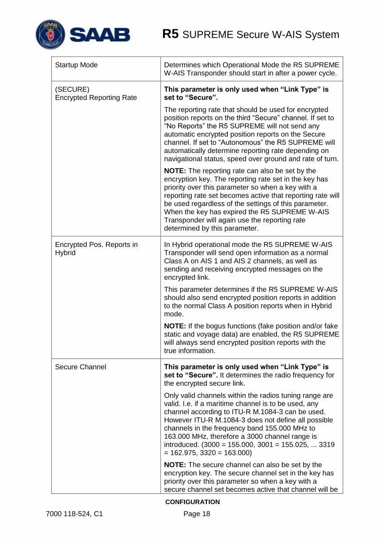
Startup Mode Determines which Operational Mode the R5 SUPREME W-AIS Transponder should start in after a power cycle.
(SECURE) Encrypted Reporting Rate
This parameter is only used when “Link Type” is set to “Secure”.
The reporting rate that should be used for encrypted position reports on the third “Secure” channel. If set to “No Reports” the R5 SUPREME will not send any automatic encrypted position reports on the Secure channel. If set to “Autonomous” the R5 SUPREME will automatically determine reporting rate depending on navigational status, speed over ground and rate of turn.
NOTE: The reporting rate can also be set by the encryption key. The reporting rate set in the key has priority over this parameter so when a key with a reporting rate set becomes active that reporting rate will be used regardless of the settings of this parameter. When the key has expired the R5 SUPREME W-AIS Transponder will again use the reporting rate determined by this parameter.
Encrypted Pos. Reports in Hybrid
In Hybrid operational mode the R5 SUPREME W-AIS Transponder will send open information as a normal Class A on AIS 1 and AIS 2 channels, as well as sending and receiving encrypted messages on the encrypted link.
This parameter determines if the R5 SUPREME W-AIS should also send encrypted position reports in addition to the normal Class A position reports when in Hybrid mode.
NOTE: If the bogus functions (fake position and/or fake static and voyage data) are enabled, the R5 SUPREME will always send encrypted position reports with the true information.
Secure Channel This parameter is only used when “Link Type” is set to “Secure”. It determines the radio frequency for the encrypted secure link.
Only valid channels within the radios tuning range are valid. I.e. if a maritime channel is to be used, any channel according to ITU-R M.1084-3 can be used. However ITU-R M.1084-3 does not define all possible channels in the frequency band 155.000 MHz to 163.000 MHz, therefore a 3000 channel range is introduced. (3000 = 155.000, 3001 = 155.025, ... 3319 = 162.975, 3320 = 163.000)
NOTE: The secure channel can also be set by the encryption key. The secure channel set in the key has priority over this parameter so when a key with a secure channel set becomes active that channel will be

R5 SUPREME Secure W-AIS System
CONFIGURATION
7000 118-524, C1 Page 19
used regardless of the settings of this parameter. When the key has expired the R5 SUPREME W-AIS Transponder will again use the channel determined by this parameter.
Secure Channel Char. This parameter is only used when “Link Type” is set to “Secure”.
Determines which channel character should be used in VDO/VDM messages for the third Secure channel. The normal AIS 1 and AIS 2 channels have ‘A’ and ‘B’ as channel characters. The Secure channel has ‘C’ as default but it can be change to any letter between ‘C’ and ‘Z’.
(BFT/STEDS) Encrypted Reporting Rate
This parameter is only used when “Link Type” is set to “BFT” or “STEDS”.
Determines the reporting rate for encrypted messages on AIS 1 and AIS 2 channels when in Tactical (Protected) or Hybrid operational mode.
BFT/STEDS Alternative Mode This parameter is only used when “Link Type” is set to “BFT” or “STEDS”.
When this parameter is set to “Enabled” the R5 SUPREME W-AIS transponder uses an alternative implementation of BFT and STEDS transmissions to be compatible with certain other manufacturers of W-AIS transponders.
As default this parameter is set to “Disabled” and in that case the R5 SUPREME W-AIS transponder will be backwards compatible with the R4SN and R4SWN transponder systems.
3.2 Static Data Configuration
When the link settings have been configured (see section 3.1) it is important to configure static data parameters for the encrypted link. This is done in the W-AIS Static Data view which is accessed from Main Menu Configuration W-AIS Static Data. The table below describes the parameters in the Static Data view:

R5 SUPREME Secure W-AIS System
CONFIGURATION
7000 118-524, C1 Page 20
Figure 8 – W-AIS Static Data
Table 4 – W-AIS Static Data Parameters
Parameter Name Description
Secure ID Only used when “Link Type” is set to “Secure”.
The Secure ID is the identification assigned to the vessel. The complete Secure MMSI will have a structure of 999OIIIII, where O is the Organization ID and IIIII is the Secure ID.
Valid values for Secure ID are 0-65535.
Secure Org. ID Only used when “Link Type” is set to “Secure”.
The Secure Organization ID is used to filter messages on the secure encrypted link. The R5 SUPREME W-AIS Transponder will disregard all encrypted messages that have a different Organization ID than itself.
Valid values for Organization ID are 0-7.
NOTE: The Org.ID can also be set by the encryption key. The Org.ID set in the key has priority over this parameter so when a key with an Org.ID set becomes active that Org.ID will be used regardless of the settings of this parameter. When the key has expired the R5 SUPREME W-AIS Transponder will again use the Org.ID determined by this parameter.
BFT DAC Only used when “Link Type” is set to “BFT”.
The DAC parameter is an international application identifier. R5 SUPREME transponder units using BFT Link Type must have the same BFT DAC and BFT FI in order to communicate in Tactical mode.
BFT FI Only used when “Link Type” is set to “BFT”.
The FI parameter is a Function identifier. R5 SUPREME transponder units using BFT Link Type must have the same BFT DAC and BFT FI in order to

R5 SUPREME Secure W-AIS System
CONFIGURATION
7000 118-524, C1 Page 21
communicate in Tactical mode.
STEDS Asset Type Only used when “Link Type” is set to “STEDS”.
This parameter defines the unit’s nationality based on Maritime Identification Digits (MID) assigned by ITU to each nation. In some applications the parameter is used to define vessel type.
3.3 Configure Bogus Id:s
The R5 SUPREME W-AIS transponder offers a way to quickly change identity on the VHF link in order for the vessel to hide its true identity. The R5 SUPREME Secure W-AIS transponder can store up to five different bogus identifications with different static data information. The user can then quickly switch between the true identity and one of the five bogus identifications by choosing the current identity in the Operational Mode view.
The data for the five bogus identifications can be configured in the Bogus Id views which are accessed from Main Menu Maintenance Configuration W-AIS Bogus ID:s.
Figure 9 – Bogus ID Configuration
For each bogus id, the following data can be altered:
Parameter Name Description
MMSI Maritime Mobile Service Identity reported by own ship
IMO International Maritime Organization number reported by own ship
Ship Name Ship name reported by own ship
Call Sign Call sign reported by own ship
Ship Type Type of Ship according to ITU-R M.1371. Both numerical input and selection from list is possible.
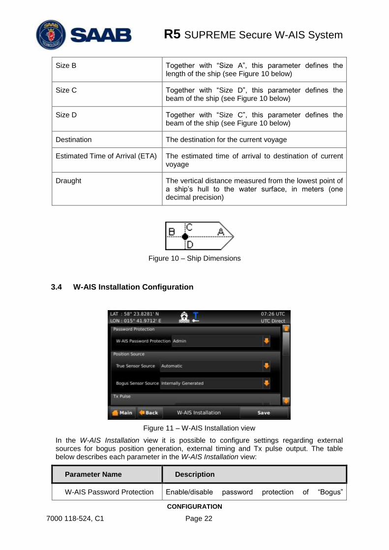
Size A Together with “Size B”, this parameter defines the length of the ship (see Figure 10 below)
R5 SUPREME Secure W-AIS System
CONFIGURATION
7000 118-524, C1 Page 22
Size B Together with “Size A”, this parameter defines the length of the ship (see Figure 10 below)
Size C Together with “Size D”, this parameter defines the beam of the ship (see Figure 10 below)
Size D Together with “Size C”, this parameter defines the beam of the ship (see Figure 10 below)
Destination The destination for the current voyage
Estimated Time of Arrival (ETA) The estimated time of arrival to destination of current voyage
Draught The vertical distance measured from the lowest point of a ship’s hull to the water surface, in meters (one decimal precision)
Figure 10 – Ship Dimensions
3.4 W-AIS Installation Configuration
Figure 11 – W-AIS Installation view
In the W-AIS Installation view it is possible to configure settings regarding external sources for bogus position generation, external timing and Tx pulse output. The table below describes each parameter in the W-AIS Installation view:
Parameter Name Description
W-AIS Password Protection Enable/disable password protection of “Bogus”

R5 SUPREME Secure W-AIS System
CONFIGURATION
7000 118-524, C1 Page 23
configuration such as Bogus ID:s, bogus position source, internally generated bogus position.
If set to “None”, no password is required to configure the bogus settings. If set to “Admin” the user will be prompted for the Admin level password when configuring bogus settings.
True Sensor Source Determines from what port the sensor information shall be taken for non-bogus position reports.
If set to “Automatic” the R5 SUPREME transponder will automatically select sensor information from the highest prioritized port with available information. All ports except that specified as Bogus Sensor Source are checked.
Bogus Sensor Source Determines from what source the sensor information shall be taken when sending bogus position reports. The chosen source must provide latitude, longitude, COG and SOG in order for the R5 SUPREME transponder to use the information.
If set to internally generated, the R5 SUPREME will calculate the position by using the start values configured in the Bogus Position view. See section 3.9 for more details.
Tx Pulse If set to enabled, the R5 SUPREME Transponder will output a binary signal indicating when the transponder is transmitting.
When e.g. the VHF antenna is shared between several VHF systems, the Tx pulse can be used to indicate to the other systems when the VHF antenna is used by the R5 SUPREME for transmission.
See section for 6.2 for more details about the Tx Pulse.
Tx Pulse Polarity Determines if the Tx Pulse should be active low or active high.
If set to “Active High” the binary signal will be high (logical “1”) during transmission and low (logical “0”) otherwise.
See section for 6.2 for more details about the Tx Pulse.
Tx Pulse Prior Offset (ms) Determines how many milliseconds before transmission the Tx Pulse shall become active.
See section for 6.2 for more details about the Tx Pulse.
Tx Pulse Trailing Offset (ms) Determines how many milliseconds after transmission the Tx Pulse shall be active.
See section for 6.2 for more details about the Tx Pulse.

R5 SUPREME Secure W-AIS System
CONFIGURATION
7000 118-524, C1 Page 24
Use External Timing Determines if the R5 SUPREME Transponder shall use an external source for timing instead of the internal GPS.
See section 6.4 for more details about external timing.
1PPS Edge Determines if the external 1PPS pulse should be detected on rising or falling edge.
See section 6.4 for more details about external timing.
1PPS Offset to ZDA The offset in seconds between the 1PPS pulse and the corresponding ZDA.
See section 6.4 for more details about external timing.
ZDA Input Port The port where the ZDA is input when using external timing.
See section 6.4 for more details about external timing.

R5 SUPREME Secure W-AIS System
CONFIGURATION
7000 118-524, C1 Page 25
3.5 Encryption Keys
Encryption keys are generated using the Secure AIS Key Generator tool (product number 7000 100-776). The keys can be printed on a paper sheet, similar to that illustrated in the figure below or saved on file and distributed electronically. For details of the Secure AIS Key Generator, see “Secure AIS Key Generator – Operator’s Manual” with p/n 7000 100-777.
A new Secure Encryption Key is either entered manually via the graphical interface of the R5 SUPREME CDU or read from a USB memory inserted in the USB interface behind the front hatch of the R5 SUPREME CDU.
All encryption key sub views can be accessed from Encryption Key menu; Main Menu Maintenance Configuration W-AIS Encryption Keys.
Figure 12 – Encryption Key Menu

R5 SUPREME Secure W-AIS System
CONFIGURATION
7000 118-524, C1 Page 26
3.5.1 View and Delete Encryption Keys
To view a list of all keys currently set in the R5 SUPREME W-AIS Transponder System go to the Key List view which is accessed from Main Menu Maintenance Configuration W-AIS Encryption Keys Key List.
Figure 13 – Key List
The list shows all keys sorted by time when they become active. The keys can also have additional settings such as Secure Channel, Reporting Rate, Cipher and Org.ID. When selecting a key in the list the additional key settings for the selected key are shown beneath the list. The currently used key (if any) is marked with a blue arrow in the right column of the list.
To delete a key from the R5 SUPREME Transponder, select it in the list and press “Delete”. Enter the user password when prompted to delete the selected key.
It is also possible to quickly delete ALL keys in the transponder by pressing the button “Delete All” and then confirm the action in the appearing popup window.
3.5.2 Distributed Key Input
To manually enter the key generated by the Secure AIS Key Generator, go to the Distributed Key Input view which accessed from Main Menu Maintenance Configuration W-AIS Encryption Keys Distributed Key Input.
Figure 14 – Distributed Key Input
To enter and validate the key, perform the following:
1. Choose if the input method should be hexadecimal or numerical input.

R5 SUPREME Secure W-AIS System
CONFIGURATION
7000 118-524, C1 Page 27
NOTE: Numerical input format keys will not be available in all Secure Key generator releases.
2. Choose a key index for the key. The R5 SUPREME W-AIS Transponder can have up to 127 keys in the memory at the same time. The R5 SUPREME will overwrite any existing key on the given index as long as the keys don’t overlap in time. If the key index is set to “0”, the R5 SUPREME Transponder will automatically try to save the key on the next free index.
3. Fill in the hexadecimal (or numerical) code from the generated paper sheet (or key file) in the fields named “Key Part 1” to “Key Part 4”.
4. When all 60 hexadecimal (or 75 numerical) characters have been input, press the “Save” button.
5. If the key is valid, a popup will appear with information about the key settings:
Figure 15 – Valid Key
If the key settings are as expected, press “Yes” to try to save the key.
6. A virtual keyboard popup prompting for password will appear. Enter the correct password (default user password is “user”) and press ENTER on the virtual keyboard.
7. If the key is successfully set it will automatically be used by R5 SUPREME Transponder from the key’s start time until it expires. A key symbol will appear under the Operational Mode icon in the status bar if the key is currently used.
3.5.3 Keys on USB Memory
The R5 SUPREME W-AIS Transponder can load keys from USB memory. This is done in the Keys on USB view which is accessed from Main Menu Maintenance Configuration W-AIS Encryption Keys Keys on USB.
In addition to load keys, keys can be sent on VHF secure link to other users on the secure VHF link. Keys sent over VHF secure link are sent as encrypted messages using broadcast transmissions. Users sharing same secure channel configuration and same secure key are able to receive new secure keys sent on secure link. See section 3.5.5 for handling of secure keys received on secure link.
R5 SUPREME Secure W-AIS System
CONFIGURATION
7000 118-524, C1 Page 28
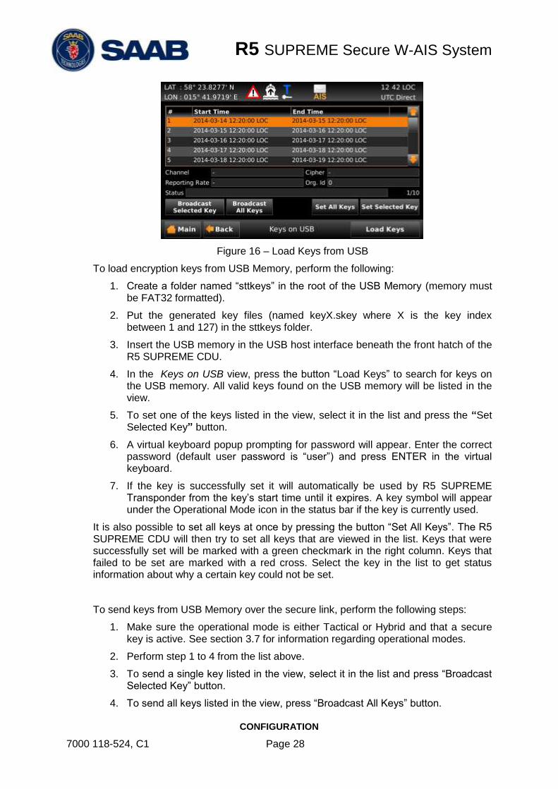
Figure 16 – Load Keys from USB
To load encryption keys from USB Memory, perform the following:
1. Create a folder named “sttkeys” in the root of the USB Memory (memory must be FAT32 formatted).
2. Put the generated key files (named keyX.skey where X is the key index between 1 and 127) in the sttkeys folder.
3. Insert the USB memory in the USB host interface beneath the front hatch of the R5 SUPREME CDU.
4. In the Keys on USB view, press the button “Load Keys” to search for keys on the USB memory. All valid keys found on the USB memory will be listed in the view.
5. To set one of the keys listed in the view, select it in the list and press the “Set Selected Key” button.
6. A virtual keyboard popup prompting for password will appear. Enter the correct password (default user password is “user”) and press ENTER in the virtual keyboard.
7. If the key is successfully set it will automatically be used by R5 SUPREME Transponder from the key’s start time until it expires. A key symbol will appear under the Operational Mode icon in the status bar if the key is currently used.
It is also possible to set all keys at once by pressing the button “Set All Keys”. The R5 SUPREME CDU will then try to set all keys that are viewed in the list. Keys that were successfully set will be marked with a green checkmark in the right column. Keys that failed to be set are marked with a red cross. Select the key in the list to get status information about why a certain key could not be set.
To send keys from USB Memory over the secure link, perform the following steps:
1. Make sure the operational mode is either Tactical or Hybrid and that a secure key is active. See section 3.7 for information regarding operational modes.
2. Perform step 1 to 4 from the list above.
3. To send a single key listed in the view, select it in the list and press “Broadcast Selected Key” button.
4. To send all keys listed in the view, press “Broadcast All Keys” button.
R5 SUPREME Secure W-AIS System
CONFIGURATION
7000 118-524, C1 Page 29
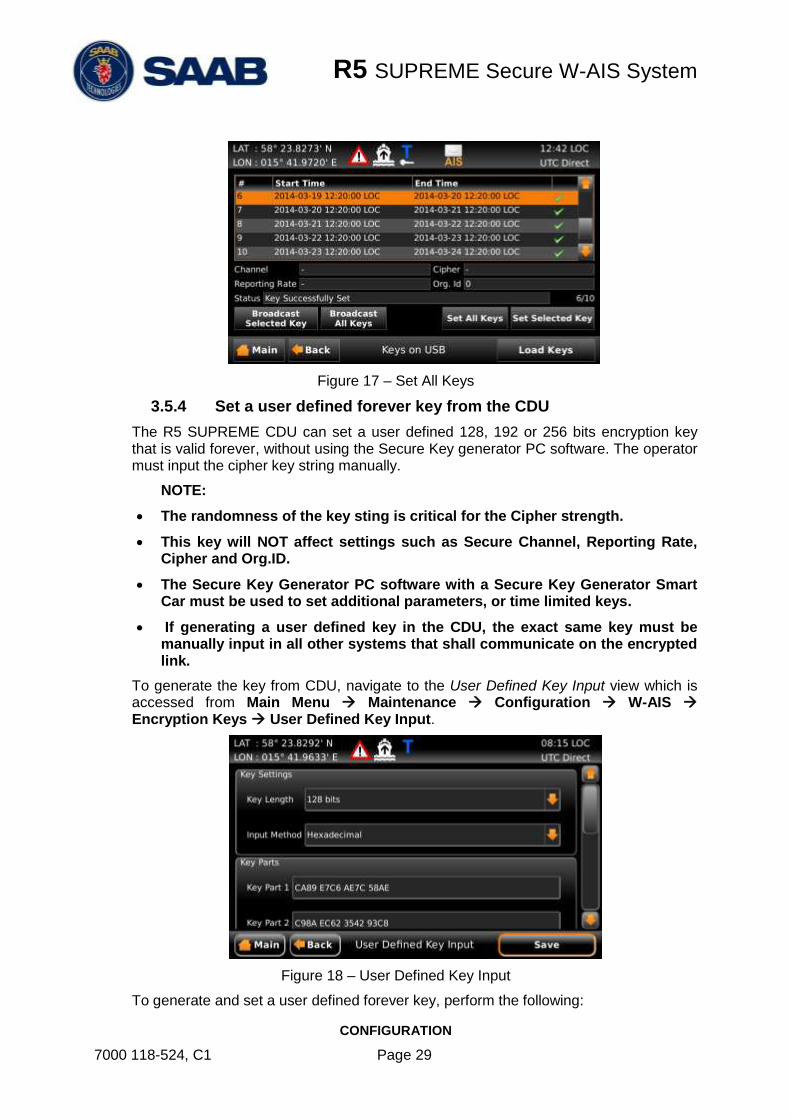
Figure 17 – Set All Keys
3.5.4 Set a user defined forever key from the CDU
The R5 SUPREME CDU can set a user defined 128, 192 or 256 bits encryption key that is valid forever, without using the Secure Key generator PC software. The operator must input the cipher key string manually.
NOTE:
The randomness of the key sting is critical for the Cipher strength.
This key will NOT affect settings such as Secure Channel, Reporting Rate, Cipher and Org.ID.
The Secure Key Generator PC software with a Secure Key Generator Smart Car must be used to set additional parameters, or time limited keys.
If generating a user defined key in the CDU, the exact same key must be manually input in all other systems that shall communicate on the encrypted link.
To generate the key from CDU, navigate to the User Defined Key Input view which is accessed from Main Menu Maintenance Configuration W-AIS Encryption Keys User Defined Key Input.
Figure 18 – User Defined Key Input
To generate and set a user defined forever key, perform the following:

R5 SUPREME Secure W-AIS System
CONFIGURATION
7000 118-524, C1 Page 30
1. Choose the desired key length of 128, 192 or 256 bits
2. Choose the input method (hexadecimal or numerical).
3. Fill in the encryption key data in the key parts parameter fields. The number of key part fields will vary depending on chosen key length.
4. Press “Save”
5. A confirmation popup will appear, press “Yes”.
6. A virtual keyboard will appear. Input the correct user level password and press ENTER on the virtual keyboard to set the encryption key in the transponder.
The key will be valid forever or until the next encryption key in the key list becomes valid.
NOTE: Make sure that the same key length, input method and key data parts is input for all R5 W-AIS transponder systems that need to communicate with each other.
3.5.5 Keys Received on Secure Link
The R5 SUPREME CDU can receive secure keys from another user on the secure link. This is only possible if the sender and receiver is using the same key and shares the same organisation id. To manage keys received on secure link, navigate to Main Menu Maintenance Configuration W-AIS Encryption Keys Keys Received on Secure Link
Figure 19 – Keys Received on Secure Link
If new secure keys are received on the secure link, the icon is displayed in the status bar. The list displays the received keys including sender. Received keys can either be set or deleted.
3.6 Set Secure Time
The automatic encryption key handling in the R5 SUPREME W-AIS Transponder cannot function without correct time/date information. The transponder will receive time from the internal GPS receiver. If the internal GPS receiver is not functioning or position fix is not available, the transponder will synchronize on received base station messages on the VHF link. If neither of these time sources are available, it is possible to force set the time in the transponder from the R5 SUPREME CDU so that the key handling will continue to work. The time in R5 SUPREME Transponder can be set from the Secure Time view
R5 SUPREME Secure W-AIS System
CONFIGURATION
7000 118-524, C1 Page 31
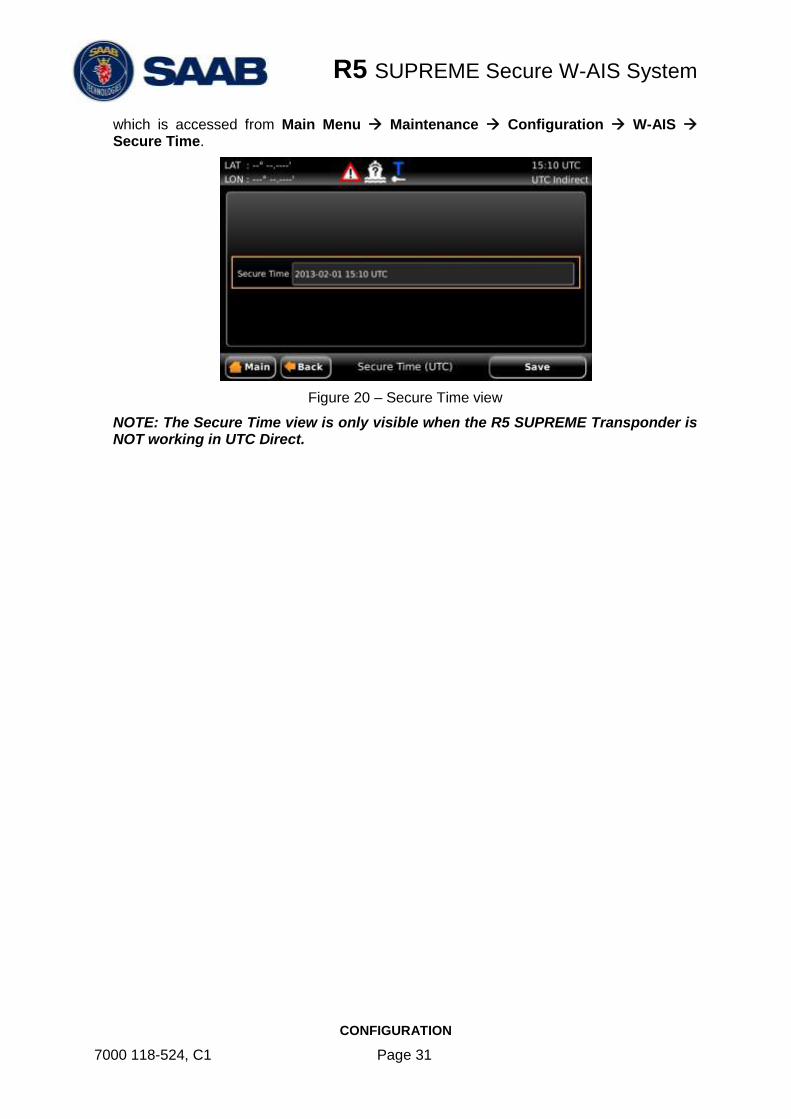
which is accessed from Main Menu Maintenance Configuration W-AIS Secure Time.
Figure 20 – Secure Time view
NOTE: The Secure Time view is only visible when the R5 SUPREME Transponder is NOT working in UTC Direct.

R5 SUPREME Secure W-AIS System
CONFIGURATION
7000 118-524, C1 Page 32
3.7 Operational Modes
There are five different operational modes for the R5 SUPREME W-AIS Transponder System. Regardless of mode, the R5 SUPREME W-AIS Transponder will always receive standard AIS messages on channels AIS 1 and AIS 2 and output the information on serial interface just as a normal Class A transponder. In all modes except the normal mode, information received on the encrypted link (if defined) will be displayed and output as well.
The current active mode is shown in the status bar of the R5 SUPREME. The following operational mode icons can appear:
Normal Mode
Silent Mode
Tactical Mode
Hybrid Mode
External Mode
If there is a valid key set and currently used in the system, a key icon ( ) will appear underneath the operational mode icon.
Operational mode can be changed in the Operational Mode view which is accessed by pressing the icon in the status bar or from Main Menu AIS Operational Mode.
Figure 21 – Operational Mode (Quick view by pressing icon)

R5 SUPREME Secure W-AIS System
CONFIGURATION
7000 118-524, C1 Page 33
Figure 22 – Operational Mode view
3.7.1 Normal Mode
In this mode the R5 SUPREME W-AIS system performs the functions of a normal R5 SUPREME Class A AIS Transponder system, and operates as an IMO approved unit.
Outgoing messages are broadcast in the open format on both AIS channels. The encrypted link is not active in this mode, thus no encrypted messages will be received or sent on the link.
NOTE: When switching to Normal operational mode, any active bogus AIS setting will be disabled.
3.7.2 Silent Mode
The unit will not broadcast any messages and it will not respond to any interrogation message from other units. The R5 SUPREME will receive standard AIS messages, like any normal Class A AIS Transponder. If an encrypted link has been defined, the unit will also be able to receive and decrypt messages received over the encrypted link.
3.7.3 Tactical Mode
The R5 SUPREME W-AIS Transponder receives and processes standard AIS messages and messages on the encrypted link. The R5 SUPREME W-AIS will automatically generate position and status reports for broadcast on the encrypted link. The unit will not broadcast any unencrypted messages and it will not respond to any unencrypted interrogation messages from other units.
User generated messages can also be broadcast on the encrypted link.
The encrypted link has to be configured in order to make this mode operational, see section 3.1.
3.7.4 Hybrid Mode
This mode can typically be used before switching to Tactical mode and after operation in Tactical mode. The encrypted link is active and the R5 SUPREME W-AIS receive both open AIS messages and messages on the encrypted link. The R5 SUPREME W-AIS will also transmit both standard AIS messages on the AIS frequencies and encrypted messages on the encrypted link.
The Hybrid operational mode is also used to transmit bogus reports on the normal AIS channels while sending true information on the encrypted link.

R5 SUPREME Secure W-AIS System
CONFIGURATION
7000 118-524, C1 Page 34
3.7.5 External Mode
This mode allows for an external system to handle encryption and decryption of binary messages.
There is no autonomous transmission of position reports in this mode. Only externally input ABM/BBM messages will be transmitted on channel A and B on the VDL.
ABM/BBM messages input in this mode will NOT be encrypted or decrypted by the transponder, encryption MUST be done in an external system or the content will be transmitted unencrypted.
If an encryption key is set, Secure, BFT or STEDS messages may, depending on set Link type, be decrypted, displayed and output. The system will not process channel management messages (unless Secure Link type is used) and will not respond to DSC interrogations.
3.8 Use Bogus Id
The R5 SUPREME W-AIS Transponder has a set of bogus id:s with false static and voyage data. The user can configure the information of each bogus id as described in section 3.3. The user can then quickly change between true static and voyage data and one of the bogus id:s by changing the parameter “Bogus ID” in the Operational Mode view accessed from Main Menu AIS Operational Mode.
NOTE: Bogus transmission is not possible in Normal operational mode, only in Hybrid mode.
If one of the bogus id:s are activated, the R5 SUPREME Secure W-AIS Transponder will use that MMSI and the static and voyage data for the transmissions on the VHF link. An icon will appear in status bar of the R5 SUPREME CDU indicating that bogus id is in use. The following bogus icons can be shown in the CDU:
Bogus ID in use, (MMSI and static and voyage data).
Bogus Position in use (latitude, longitude, COG and SOG).
Both Bogus ID and Bogus Position in use
3.9 Use Bogus Position
The R5 SUPREME W-AIS Transponder can send bogus position information on the VHF link by enabling the “Bogus Position” function. When this function is enabled, the transponder will change the latitude, longitude, COG and SOG values (as well as heading and ROT if provided) in the position reports. The bogus position data that is sent can either be internally generated or taken from an external bogus position source connected on one of the serial ports.
The user must specify the bogus position source in the W-AIS Installation view, see section 3.4.
NOTE: Bogus transmission is not possible in Normal operational mode.
R5 SUPREME Secure W-AIS System
CONFIGURATION
7000 118-524, C1 Page 35
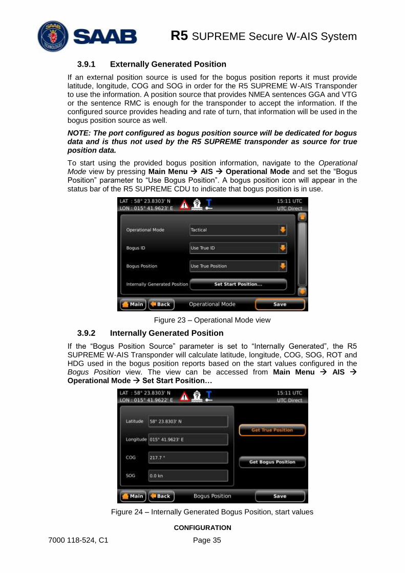
3.9.1 Externally Generated Position
If an external position source is used for the bogus position reports it must provide latitude, longitude, COG and SOG in order for the R5 SUPREME W-AIS Transponder to use the information. A position source that provides NMEA sentences GGA and VTG or the sentence RMC is enough for the transponder to accept the information. If the configured source provides heading and rate of turn, that information will be used in the bogus position source as well.
NOTE: The port configured as bogus position source will be dedicated for bogus data and is thus not used by the R5 SUPREME transponder as source for true position data.
To start using the provided bogus position information, navigate to the Operational Mode view by pressing Main Menu AIS Operational Mode and set the “Bogus Position” parameter to “Use Bogus Position”. A bogus position icon will appear in the status bar of the R5 SUPREME CDU to indicate that bogus position is in use.
Figure 23 – Operational Mode view
3.9.2 Internally Generated Position
If the “Bogus Position Source” parameter is set to “Internally Generated”, the R5 SUPREME W-AIS Transponder will calculate latitude, longitude, COG, SOG, ROT and HDG used in the bogus position reports based on the start values configured in the Bogus Position view. The view can be accessed from Main Menu AIS Operational Mode Set Start Position…
Figure 24 – Internally Generated Bogus Position, start values

R5 SUPREME Secure W-AIS System
CONFIGURATION
7000 118-524, C1 Page 36
The configured latitude and longitude will be used as start position and the R5 SUPREME transponder will then use the configured values for COG and SOG to calculate new latitude and longitude for each bogus position report. The reported heading will have the same value as COG (but truncated) and the reported ROT will always be zero when using internally calculated bogus position.
If the button “Get True Position” is pressed, the start value parameters will automatically be filled in with the current true position. If the button “Get Bogus Position” is pressed, the start values will be filled in with the current reported bogus position. It is then possible to make changes to the start values before they are saved in the R5 SUPREME transponder by pressing “Save”.
NOTE: The start values will not be stored in non-volatile memory. If the R5 SUPREME W-AIS is rebooted while using internally generated bogus position, the transponder will set the position to invalid in the transmitted bogus reports.
3.10 Target List and Plot
When the operational mode is set to anything other than “Normal”, the R5 SUPREME W-AIS Transponder can receive encrypted messages on the encrypted link (Secure, BFT or STEDS). Targets received on the encrypted link will be marked as “Secure Targets” with a green colour in target list and plot while normal Class A targets are marked with orange colour in target list and white colour in plot.
Figure 25 – Target List, Secure Target marked with green colour
Figure 26 – Plot, Secure Target marked with green colour

R5 SUPREME Secure W-AIS System
CONFIGURATION
7000 118-524, C1 Page 37
Figure 27 – Extended Info
3.11 Message Handling
Message Handling works as for a normal Class A when in Normal Operational Mode. It is also possible to send encrypted SRM or text messages when working in Tactical and Hybrid Operational Mode and BFT Link or Secure Link is used. It is currently NOT possible to send encrypted SRM and text messages when using STEDS Link.
To send an encrypted SRM or text message, the system must be in the Tactical or Hybrid Operational Mode and the link type must be set to “Secure ” or “BFT”, see section 3.1. A valid key must also have been entered as described in section 3.5.
When using BFT link type, all SRM and text messages will be encrypted in both Tactical and Hybrid mode. When the Secure link type is used, the messages will be encrypted if the channel is set to “Secure”.
Sending an SRM or text message over the encrypted link is done in the same manner as sending a message in a normal R5 SUPREME Class A Transponder System. The AIS Message Send view is accessed from Main Menu Messages AIS Messages Send.
Choose between addressed or broadcast SRM or text message, select destination and enter text as described in your R5 SUPREME AIS Transponder System Manual, in section “Handling Safety Related Messages (SRM) and Text Messages”.
Note: It is not possible to send SRMs when in the Silent or External Operational Mode.
Figure 28 – Send SRM and Text Messages on Secure Link

R5 SUPREME Secure W-AIS System
CONFIGURATION
7000 118-524, C1 Page 38
3.12 Alarms
There is one new alarm in the R5 SUPREME W-AIS Transponder System compared to the normal R5 SUPREME Class A transponder:
3.12.1 W-AIS: Encryption key unavailable
This alarm is active if there is no active encryption key set in the R5 SUPREME W-AIS transponder. The alarm can be active even if R5 SUPREME W-AIS transponder has encryption keys set in the memory if none of the keys has a valid time period for the current UTC time.
The alarm will appear as a popup window when it becomes active and it will also affect the external alarm relay. The alarm can however be disabled in the Alarm Config view which is accessed from Main Menu Configuration Alarm.
3.13 Situation Relay
Situation Relay requests and broadcasts of own situation view is accessed from the Situation Relay view by pressing Main Menu AIS Situation Relay.
To request a situation view from another transponder in the organization group:
1. Select filter type from the Filter Type drop-down menu. In case a parameter has to be given, an input field is shown.
2. Select to which MMSI the request should be sent from the from MMSI input field.
3. Press Request Targets button to send the request. A popup dialog will show the status of the request.
It is also possible to send own situation view to other targets in the organization group. This is sent as a broadcast message to all members in the organization group.
To broadcast own situation view:
1. Select filter type from the Filter Type drop-down menu. In case a parameter has to be given, an input field is shown.
2. Press Broadcast Own Targets button.
3. A popup dialog will show the status of the broadcast.

R5 SUPREME Secure W-AIS System
CONFIGURATION
7000 118-524, C1 Page 39
Received relayed targets are shown in the target list and target plot view. Relayed targets are displayed with a blue icon.
Relayed targets are shown in blue colour in the target plot view.
It is possible to query for details of a relayed target such as exact position and ship name when pressing the OPT button on a selected relayed target. This is also possible if the OPT button is pressed from within the Extended Target Info view for a relayed target.
Display of relayed targets in target list and plot view can be controlled by setting the configuration parameter W-AIS: Show relayed targets by pressing Main Menu Maintenance Configuration AIS Display Parameters.
3.14 Target Classification
The R5 SUPREME AIS system allows for targets to be classified and easy to distinguish from other target by displaying classified targets in a different colour in the target list view and target plot view. Refer to R5 SUPREME AIS System Manual for instructions on how to add target classifications.
R5 SUPREME Secure W-AIS System
CONFIGURATION
7000 118-524, C1 Page 40
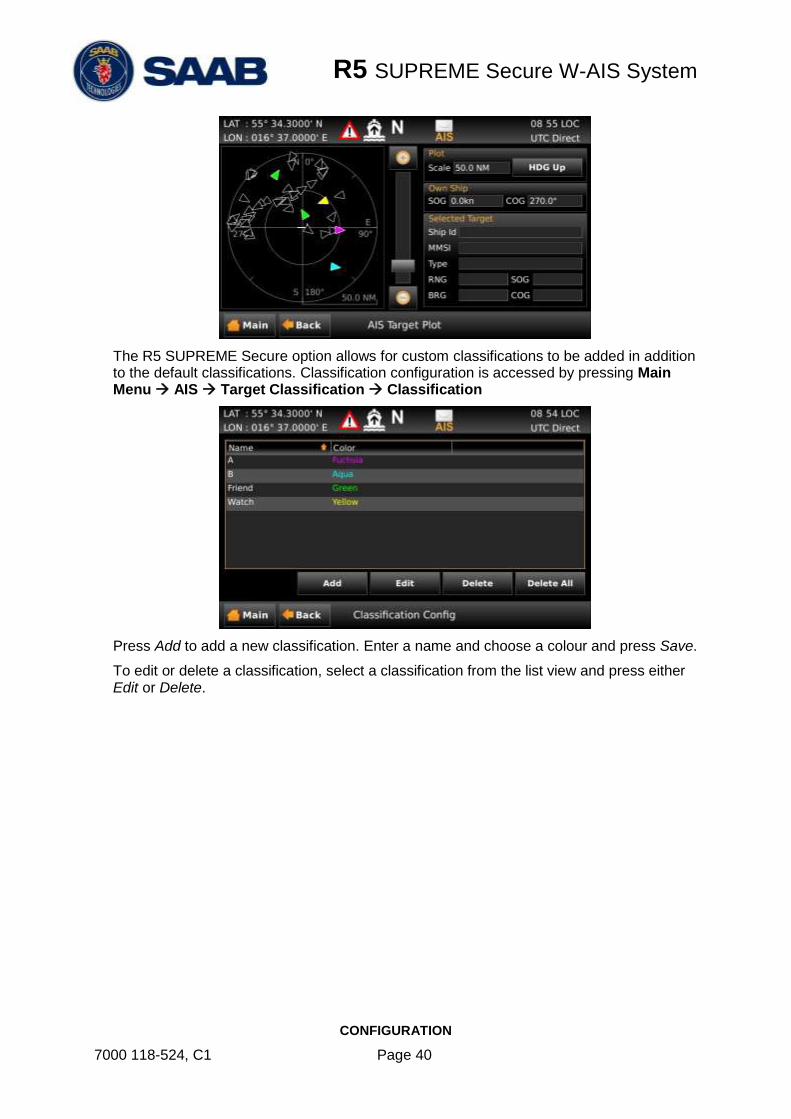
The R5 SUPREME Secure option allows for custom classifications to be added in addition to the default classifications. Classification configuration is accessed by pressing Main Menu AIS Target Classification Classification
Press Add to add a new classification. Enter a name and choose a colour and press Save.
To edit or delete a classification, select a classification from the list view and press either Edit or Delete.

R5 SUPREME Secure W-AIS System
OPERATION
7000 118-524, C1 Page 41
4 OPERATION
This chapter consists of a few examples of use cases and describes how to operate the R5 SUPREME W-AIS transponder system.
The following use cases assumes that the all R5 SUPREME Transponder systems has been installed and configured as normal Class A systems in accordance with R5 SUPREME AIS Transponder System Manual (p/n 7000 118-300). The systems must have valid MMSI set in order to transmit.
All systems should also have the latest software and correct W-AIS licenses, see chapter 2 for information about software and license upgrades.
4.1 Start encrypted link on a third dedicated channel
To start an encrypted link on a dedicated third channel between two or more R5 SUPREME W-AIS transponder systems, perform the following for each system:
1. Navigate to Link Settings view, Main Menu Maintenance Configuration W-AIS Link Settings. In the Link Settings view, the following parameters MUST be set to the same values on all R5 SUPREME W-AIS systems:
Link Type = “Secure”
Cipher
Secure Channel
2. Navigate to W-AIS Static Data view, Main Menu Maintenance Configuration W-AIS Static Data. Configure the following parameters:
Secure ID – Must be UNIQUE for each system
Secure Organization ID – Must be SAME for all systems.
3. The systems are now configured and must now have the SAME encryption key in order to communicate in Tactical Operational Mode. An encryption key can be created as described in chapter 3.5 “Encryption Keys” and distributed to all R5 SUPREME W-AIS systems. The key can then be loaded in each transponder by manual input or via USB as described further in chapter 3.5.2 and 3.5.3.
NOTE: An encryption key can override the settings for Secure Channel, Secure Org. ID, Cipher and Reporting Rate. The settings of the key are displayed in the Key List view as described in chapter 0.
4. When all systems are configured and have the SAME valid encryption key, the operational mode can be changed to Tactical and thus starting encrypted communication on the secure channel.
The “Tactical Mode” icon and a key symbol should be visible in the status bar in the R5 CDU, see chapter 0.
Confirm in Target List view and Plot view that secure targets are received, see chapter 3.10.
R5 SUPREME Secure W-AIS System
OPERATION
7000 118-524, C1 Page 42
4.2 Start encrypted BFT link on AIS1 and AIS2
When the BFT link type is used, the R5 SUPREME W-AIS Transponder sends encrypted position reports wrapped in binary VDL message 8. To start encrypted communication with BFT link type, perform the following for each system:
1. Navigate to Link Settings view, Main Menu Maintenance Configuration W-AIS Link Settings. In the Link Settings view, the following parameters MUST be set to the same values on all R5 SUPREME W-AIS systems:
Link Type = “BFT”
Cipher
2. Navigate to W-AIS Static Data view, Main Menu Maintenance Configuration W-AIS Static Data. Configure the following parameters:
BFT DAC must be SAME for all systems
BFT FI must be SAME for all systems.
3. The systems are now configured and must now have the SAME encryption key in order to communicate in Tactical Operational Mode. An encryption key can be created as described in chapter 3.5 “Encryption Keys” and distributed to all R5 SUPREME W-AIS systems. The key can then be loaded in each transponder by manual input or via USB as described further in chapter 3.5.2 and 3.5.3.
NOTE: An encryption key can contain settings for Secure Channel, Secure Org. ID, and Reporting Rate. These are only applicable to Secure link type, and have no effect when using BFT link type.
4. When all systems are configured and have the SAME valid encryption key, the operational mode can be changed to Tactical and thus starting encrypted communication.
The “Tactical Mode” icon and a key symbol should be visible in the status bar in the R5 CDU, see chapter 0.
Confirm in Target List view and Plot view that encrypted targets are received, see chapter 3.10.
4.3 Start encrypted STEDS link on AIS1 and AIS2
When the STEDS link type is used, the R5 SUPREME W-AIS Transponder sends encrypted position reports wrapped in binary VDL message 25 and 26. To start encrypted communication with STEDS link type, perform the following for each system:
1. Navigate to Link Settings view, Main Menu Maintenance Configuration W-AIS Link Settings. In the Link Settings view, the following parameters MUST be set to the same values on all R5 SUPREME W-AIS systems:
Link Type = “STEDS”
Cipher
2. Navigate to W-AIS Static Data view, Main Menu Maintenance Configuration W-AIS Static Data. Configure the following parameters:
STEDS Asset Type - This parameter defines the unit’s nationality based on Maritime Identification Digits (MID) assigned by ITU to each nation. In some applications the parameter is used to define vessel type.

R5 SUPREME Secure W-AIS System
OPERATION
7000 118-524, C1 Page 43
3. The systems are now configured and must now have the SAME encryption key in order to communicate in Tactical Operational Mode. An encryption key can be created as described in chapter 3.5 “Encryption Keys” and distributed to all R5 SUPREME W-AIS systems. The key can then be loaded in each transponder by manual input or via USB as described further in chapter 3.5.2 and 3.5.3.
4. NOTE: An encryption key can contain settings for Secure Channel, Secure Org. ID, and Reporting Rate. These are only applicable to Secure link type, and have no effect when using STEDS link type.
5. When all systems are configured and have the SAME valid encryption key, the operational mode can be changed to Tactical and thus starting encrypted communication on the secure channel.
The “Tactical Mode” icon and a key symbol should be visible in the status bar in the R5 CDU, see chapter 0.
Confirm in Target List view and Plot view that encrypted targets are received, see chapter 3.10.
4.4 Start using bogus position reports
The R5 SUPREME W-AIS transponder can transmit bogus position reports when operating in Hybrid Operational Mode as described in chapter 3.9. To start using bogus position reports, perform the following:
1. Make sure that operational mode is set to “Silent” or “Tactical” before configuration of bogus position is done to ensure that true position is not transmitted openly.
2. Configure “Bogus Position Source” in the W-AIS Installation view, see chapter 3.4 for more information.
3. If bogus position source is set to “Internally Generated”, the start values for the internal calculations must be configured in the Bogus Position view as described in chapter 3.9.2.
4. Activate the bogus position function by setting the parameter “Bogus Position” to “Use Bogus Position” in the Operational Mode view.
The bogus position icon should now be visible in the status bar of the R5 CDU.
5. When the bogus position icon is shown, it is now safe to change to Hybrid Operational Mode in order to start transmission of bogus position reports on the normal AIS channels.
4.5 Start using bogus static and voyage data
The R5 SUPREME W-AIS transponder can transmit bogus static and voyage data reports when operating in Hybrid Operational Mode as described in chapter 3.8. To start using bogus ID, perform the following:
1. Make sure that operational mode is set to “Silent” or “Tactical” before configuration of bogus ID is done to ensure that true information is not transmitted openly.
2. Configure the fake static and voyage data that should be sent in the Bogus ID configuration views, see section 3.3. Up to five different bogus ID:s can be pre configured and saved.

R5 SUPREME Secure W-AIS System
OPERATION
7000 118-524, C1 Page 44
3. Activate the bogus id function by setting the parameter “Bogus ID”, in the Operational Mode view, to “Use Bogus ID x” where x corresponds to the desired pre configured bogus ID.
The bogus ID icon should now be visible in the status bar of the R5 CDU to indicate the use of fake static and voyage data on the VHF link.
4. When the bogus ID icon is shown, it is now safe to change to Hybrid Operational Mode in order to start transmission of bogus static and voyage data reports on the normal AIS channels.
4.6 Operate with a mix of R5 S W-AIS and R4S or R4SL units
To start an encrypted link compatible with the R4 Secure system, perform the following for each R5 S W-AIS system:
Follow the instructions in section 4.1, but make sure the following is observed:
Link Type = “Secure”
Cipher = AES (if available, set to DES for communication with R4SL)
Secure Channel = same as set on R4 System (default 1087)
Use the same key as used on the R4 System

R5 SUPREME Secure W-AIS System
TROUBLESHOOTING
7000 118-524, C1 Page 45
5 TROUBLESHOOTING
5.1 W-AIS Status view
The W-AIS Status view shows a summary of the Warship AIS settings that are currently used by the R5 SUPREME W-AIS transponder. Therefore it can be helpful during troubleshooting to see if there is a mismatch of settings between two R5 SUPREME W-AIS systems. In this view it is also possible to see the currently transmitted bogus position and bogus static and voyage data if these functions are enabled in the system.
Figure 29 – W-AIS Status view
5.2 Configuration mismatch
The most likely reason why two W-AIS systems cannot communicate with each other is due to configuration mismatch between the transponders. The W-AIS Status view described in section 5.1 shows the summary of the currently used W-AIS configuration. Ensure that all W-AIS systems conform to the following:
Cipher must be the same on all systems
Encryption key must be the same on all systems on must be valid for the current UTC time, see section 5.3.
Operational Mode should be set to Tactical to send encrypted messages on the encrypted link
Ensure that external Tx switch is not preventing transmissions.
MMSI must be set on all systems
Note that the encryption key may override some configured settings but the W-AIS Status view always show the currently used settings regardless if the settings is taken from configuration or active encryption key.
Depending on which link type is used, all W-AIS systems must also conform to the following:
Secure Link Type
Link Type must be set to “Secure”
Secure Org.Id must be the same on all systems
Secure ID must be unique for each system.
Secure channel frequency must be the same on all systems

R5 SUPREME Secure W-AIS System
TROUBLESHOOTING
7000 118-524, C1 Page 46
It is also good to check that the reporting rate on the secure channel is set to anything else than “No Reports” in order to send encrypted position reports on the secure link.
BFT Link Type
Link Type must be set to “BFT”
BFT DAC must be the same on all systems
BFT FI must be same for each system.
Channel A and Channel B frequency must be the same on all systems. Check the VHF Status view to see currently used frequencies for A and B channels. Any active regional area is considered when displaying the VHF Status information.
It is also good to check that the BFT/STEDS reporting rate is set to anything else than “No Reports” in order to send encrypted position reports on the encrypted link.
STEDS Link Type
Link Type must be set to “STEDS”
Channel A and Channel B frequency must be the same on all systems. Check the VHF Status view to see currently used frequencies for A and B channels. Any active regional area is considered when displaying the VHF Status information.
It is also advised to check that the BFT/STEDS reporting rate is set to anything else than “No Reports” in order to send encrypted position reports on the encrypted link.
5.3 Currently used encryption key
In order for the encrypted link to work, all W-AIS systems must use the same valid encryption key. The R5 SUPREME W-AIS system can have up to 127 encryption keys programmed with different time intervals and the transponder will automatically choose and use the key that is valid for the current UTC time. If there is a valid key currently used by the transponder, it will be indicated with a key symbol in the status bar of the R5 CDU. The W-AIS Status view will also show key index and key length for the currently used encryption key. If the R5 SUPREME W-AIS system receives a lot of faulty encrypted targets or AIS messages, it may be due to mismatching encryption keys or ciphers. To ensure that the same encryption key is used on all systems that should communicate, check the following:
The W-AIS system must have time (UTC Direct) to choose correct encryption key
Key symbol should be shown in status bar to indicate that a key is in use.
Check Key List view (see chapter 0) to see which key is active and also the valid time periods for each key
Check the W-AIS Status view to see key index and key length.
R5 SUPREME Secure W-AIS System
INSTALLATION CONSIDERATIONS
7000 118-524, C1 Page 47
6 INSTALLATION CONSIDERATIONS
The installation procedure for an R5 SUPREME AIS System is described in detail in the R5 SUPREME AIS Transponder System Manual (p/n 7000 118-300). This chapter describes additional installation steps for a R5 SUPREME W-AIS installation, not applicable for a normal Class A installation.
6.1 Installing the Silent Switch
It is possible to connect an external switch to the R5 SUPREME Transponder. This switch may be used to quickly turn off transmissions.
If the silent switch functionality is to be used, the parameter “External Switch” must be configured to “Silent Switch” in Misc. Interface view accessed from Main Menu Maintenance Configuration Interface Misc. Interfaces.
The status of the switch can be controlled by input on the brown and orange wires of the R5 Power Cable, or by connecting to the R5 AIS Junction Box (R) and (F) signals in the Ext Switch terminal block.
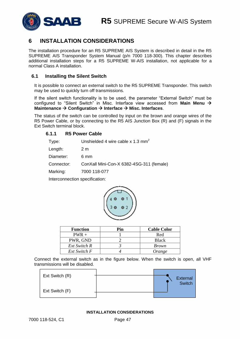
6.1.1 R5 Power Cable
Type: Unshielded 4 wire cable x 1.3 mm2
Length: 2 m
Diameter: 6 mm
Connector: ConXall Mini-Con-X 6382-4SG-311 (female)
Marking: 7000 118-077
Interconnection specification:
Function Pin Cable Color
PWR + 1 Red
PWR, GND 2 Black
Ext Switch R 3 Brown
Ext Switch F 4 Orange
Connect the external switch as in the figure below. When the switch is open, all VHF transmissions will be disabled.
External Switch
Ext Switch (R)
Ext Switch (F)
R5 SUPREME Secure W-AIS System
INSTALLATION CONSIDERATIONS
7000 118-524, C1 Page 48
6.2 Installing a Transmission (Operational) Mode switch
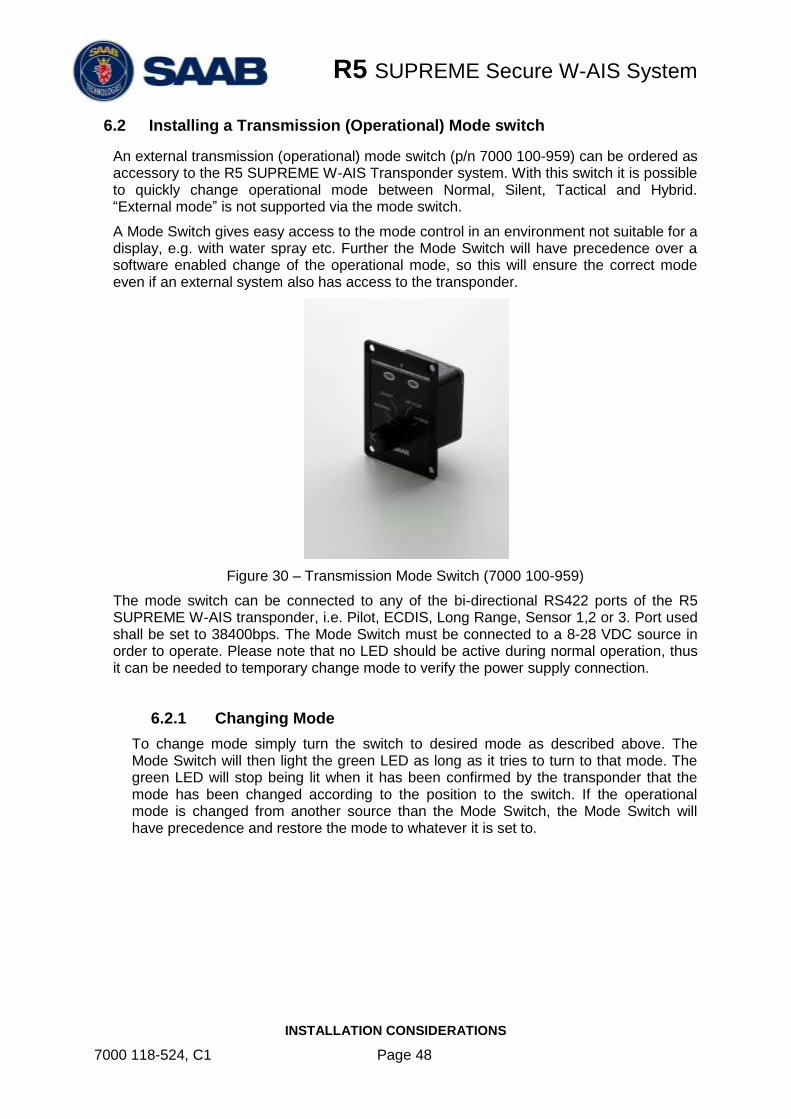
An external transmission (operational) mode switch (p/n 7000 100-959) can be ordered as accessory to the R5 SUPREME W-AIS Transponder system. With this switch it is possible to quickly change operational mode between Normal, Silent, Tactical and Hybrid. “External mode” is not supported via the mode switch.
A Mode Switch gives easy access to the mode control in an environment not suitable for a display, e.g. with water spray etc. Further the Mode Switch will have precedence over a software enabled change of the operational mode, so this will ensure the correct mode even if an external system also has access to the transponder.
Figure 30 – Transmission Mode Switch (7000 100-959)
The mode switch can be connected to any of the bi-directional RS422 ports of the R5 SUPREME W-AIS transponder, i.e. Pilot, ECDIS, Long Range, Sensor 1,2 or 3. Port used shall be set to 38400bps. The Mode Switch must be connected to a 8-28 VDC source in order to operate. Please note that no LED should be active during normal operation, thus it can be needed to temporary change mode to verify the power supply connection.
6.2.1 Changing Mode
To change mode simply turn the switch to desired mode as described above. The Mode Switch will then light the green LED as long as it tries to turn to that mode. The green LED will stop being lit when it has been confirmed by the transponder that the mode has been changed according to the position to the switch. If the operational mode is changed from another source than the Mode Switch, the Mode Switch will have precedence and restore the mode to whatever it is set to.
R5 SUPREME Secure W-AIS System
INSTALLATION CONSIDERATIONS
7000 118-524, C1 Page 49
6.2.2 Alarm Indication
The Mode Switch has a red LED which indicates alarms that are so severe that the transponder cannot fulfill its main functions. The following alarms will trigger the red LED to be lit:
Alarm Id Description
1 Tx malfunction, all transmissions have been stopped
3 Rx channel 1 malfunction, related to std AIS channel
4 Rx channel 2 malfunction, related to std AIS channel
5 Rx channel 3 malfunction, related to DSC or Secure
channel
6 General failure
70* No valid encryption key available
*) This alarm will only be used when a secure mode is active, i.e. not in normal mode
The LED will automatically turn the LED off if an alarm becomes inactive.
6.2.3 Mode Switch Technical Data
Front plate size 6 x 8 cm
Box size* 5 x 5 x 3 cm
Case IP 67
Wight Approx 140 g
Power 8 - 28 VDC
* Allow room for the connector and cable behind the box when installing.
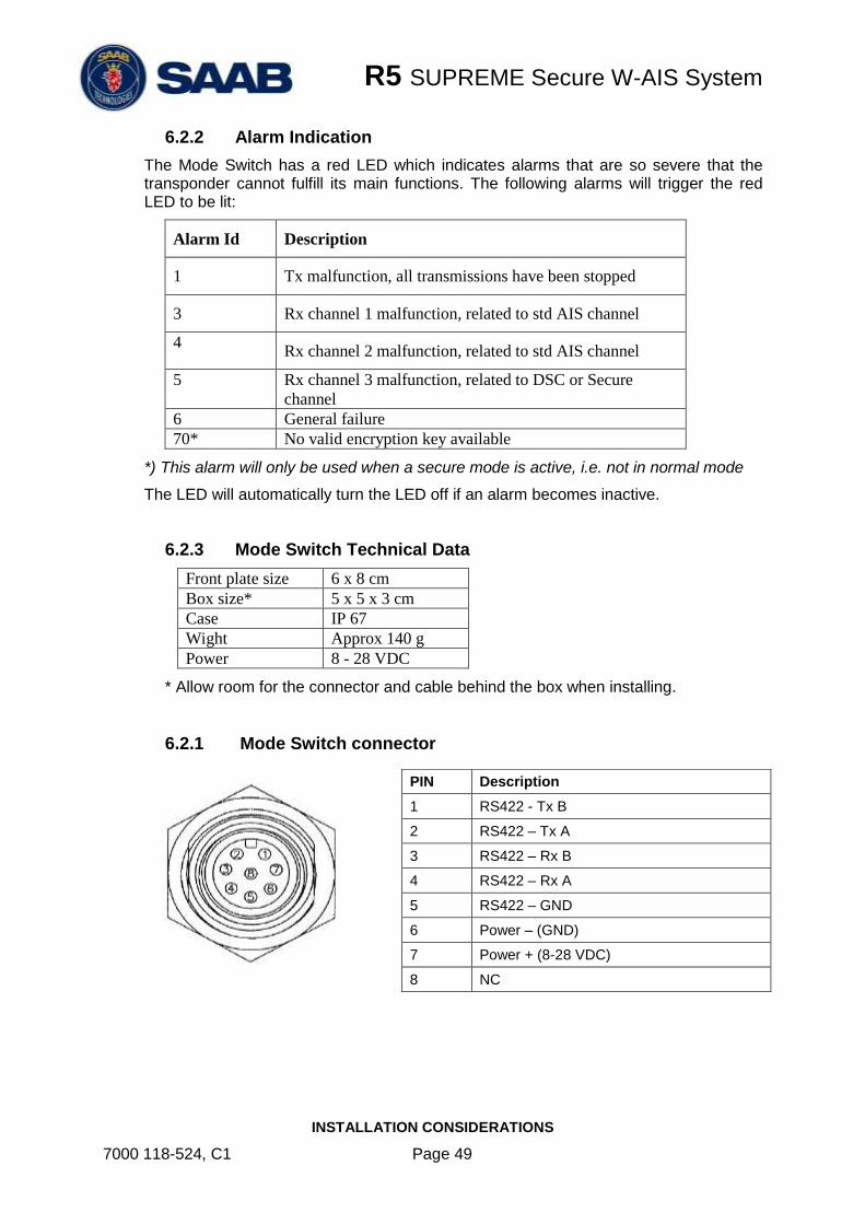
6.2.1 Mode Switch connector
PIN Description
1 RS422 - Tx B
2 RS422 – Tx A
3 RS422 – Rx B
4 RS422 – Rx A
5 RS422 – GND
6 Power – (GND)
7 Power + (8-28 VDC)
8 NC

R5 SUPREME Secure W-AIS System
INSTALLATION CONSIDERATIONS
7000 118-524, C1 Page 50
6.2.2 Mode Switch Cables
The optional contacted cables (7000 100-961 and 7000 100-962) have the following colour coding.
Color Description
Brown RS422 Tx B
Red RS422 Tx A
Orange RS422 Rx B
Yellow RS422 Rx A
Green RS422 GND
Blue Power – (GND)
Purple Power + (8 – 28 VDC)
Grey NC
6.3 Installing a device to the TX Pulse Output Signal
A device that shall react on a transmission from the R5 SUPREME W-AIS transponder shall be connected to the “General I/O 0 – Out signal” on pin 20 in the 26-pole I/O port of the R5 SUPREME transponder. In the R5 AIS Junction Box this signal is located on terminal “P10” (GPIO OUT) and labeled “GPIO OUT 0”). The discrete tx pulse output signal will be active during transmission, including configured prior offset and trailing offset time periods as described in section 3.4. It is also configurable if the pulse should be active low or active high. The tx pulse output signal has the following characteristics:
High-level output voltage
(shall be interpreted as logical “1”)
Min 2.48 V
Max 3.38 V
Low-level output voltage
(shall be interpreted as logical “0”)
Max 0.5 V
Maximum Output Current 4 mA
If the connected device requires a higher switching current than 4mA, an external optocoupler or similar should be installed to the R5 SUPREME transponder tx pulse signal. An example circuit where a LED is connected to the tx pulse output signal via an optocoupler is shown below.

R5 SUPREME Secure W-AIS System
INSTALLATION CONSIDERATIONS
7000 118-524, C1 Page 51
Figure 31 – Example: Tx Pulse with LED
In this example the parameter “Tx pulse Prior Offset” is set to 20 ms and the parameter “Tx Pulse Trailing Offset” is set to 10 ms. The LED will then be lit 20 ms before transmission and continue to be lit until 10 ms after the transmission is done.
Total length the pulse will be active
Prior offset Actual transmission Trailing offset
Figure 32 – Tx Pulse characteristic
6.4 Installing external 1PPS
To use timing from an external position source instead of the R5 SUPREME transponder internal GPS receiver, the parameter “Use External Timing” shall be set to Enabled, see section 3.4. The externally provided 1PPS shall be accurate to at least 1 µs on raising edge and be input as a TTL level on the 1PPS input (GPIO IN 0) on pin 26 in the 26-pole I/O port on the R5 SUPREME transponder. In the R5 AIS Junction Box the 1PPS input port is located on terminal “P11” (GPIO IN) and labeled “GPIO IN 0”.
NOTE: An AIS system is highly dependent on exact timing in order to transmit in the correct time slots on the VHF link. If an external timing source is used, it is VERY important to configure it correctly otherwise the R5 SUPREME transponder can transmit in the same slots as other transponders and thus VHF reception will be degraded.
6.4.1 External Timing – Examples
1) 1PPS is detected at rising edge. Offset to ZDA is 0 seconds.

R5 SUPREME Secure W-AIS System
INSTALLATION CONSIDERATIONS
7000 118-524, C1 Page 52
ZDA – 08:01:03 UTC
1PPS – 08:01:03 UTC 1PPS – 08:01:04 UTC
ZDA – 08:01:04 UTCSerial Data
1PPS Pulse
Figure 33 – 1PPS Ex. 1) Offset to ZDA = 0s
2) 1PPS is detected at rising edge. Offset to ZDA is +1 seconds.
ZDA – 08:01:02 UTC
1PPS – 08:01:03 UTC 1PPS – 08:01:04 UTC
ZDA – 08:01:03 UTCSerial Data
1PPS Pulse
Figure 34 – 1PPS Ex. 2) Offset to ZDA = +1s
3) 1PPS is detected at rising edge. Offset to ZDA is -1 seconds.
ZDA – 08:01:03 UTC
1PPS – 08:01:03 UTC 1PPS – 08:01:04 UTC
ZDA – 08:01:04 UTCSerial Data
1PPS Pulse
Figure 35 – 1PPS Ex. 3) Offset to ZDA = -1s

R5 SUPREME Secure W-AIS System
INSTALLATION CONSIDERATIONS
7000 118-524, C1 Page 53
4) 1PPS is detected at falling edge. Offset to ZDA is 0 seconds.
ZDA – 08:01:03 UTC
1PPS – 08:01:03 UTC 1PPS – 08:01:04 UTC
ZDA – 08:01:04 UTCSerial Data
1PPS Pulse
Figure 36 – 1PPS Ex. 4) Offset to ZDA = 0s, falling edge
R5 SUPREME Secure W-AIS System
APPENDIX A – CONTACT INFORMATION
7000 118-524, C1 Page 54
APPENDIX A – CONTACT INFORMATION
Saab TransponderTech AB Låsbläcksgatan 3 589 31 Linköping Sweden
Email: [email protected]


