W-CDMA/LTE Area Optimization using ML8780A/81A Shoji Hamao, Yuji Yoshida [Summary] Mobile phone networks in Japan are switching from 3G to 3.9G/4G (LTE hereafter). However, there are some overlapping frequency bands between 3G and LTE. Further, mixed 3G and LTE networks will remain in place for some years due to the high cost of replacing legacy 3G network infrastructure. Consequently, measuring instruments that can obtain stably outcome never af- fected by interference of W-CDMA/LTE from each other system are needed and then it is necessary for special consideration of difference character betwewn W-CDMA and LTE. The ML8780A/81A Area Tester with new MU878030A/MU878040A test options is ideal for optimizing mixed W-CDMA/LTE service areas. (1) 1 Introduction Recent development of mobile phone networks is focusing on Self Organizing Network (SON) 1), 2) technologies for op- timizing service areas by exchanging information between terminals and base stations without using measuring in- struments. However, direct field measurements are still required for comparing communications quality between carriers, collecting objective and stable measurement data, and examining faults. In other words, use of dedicated measuring instruments to evaluate mobile phone network service areas is not going away. We have developed the ML8780A/81A Area Tester (figure 1) as a measuring instrument for evaluating these service areas and helping the work of mobile carriers, base station installation companies, and mobile terminal makers. The ML8780A/81A is a modular design using multiple measurement modules such as the MU878010A supporting W-CDMA measurements and the MU878030A supporting LTE FDD. As part of a new lineup, we have recently launched the MU878030B LTE measurement Unit with lower power consumption than its predecessor MU878030A and supporting both the 700 and 900 MHz bands recently standardized in Japan. With this development, the MU878030B can be used for LTE Signal to Interference Ratio (SIR) stably calculations in a Fading Environment. In addition, to support LTE TDD measurements, we have re- cently launched the MU878040A TD-LTE measurement unit offering users easy measurement of time-domain switched uplink and downlink signals by identifying just the downlink timing. Combining these new measurement modules makes it easy to measure W-CDMA and LTE sys- tems simultaneously, supporting effective measurement and evaluation of mixed service areas. Figure 1 ML8780A and ML8781A Area Tester 2 LTE Measurement Items In W-CDMA systems, usually the Primary Common Pilot Channel (P-CPICH) being transmitted at a fixed level is measured. In comparison, in LTE systems, the measure- ment target is the Reference Signal used for channel esti- mates and Channel Quality Indicator (CQI) measurements. ML8780A ML8781A 23
Transcript
W-CDMA/LTE Area Optimization using ML8780A/81A
Shoji Hamao, Yuji Yoshida
[Summary] Mobile phone networks in Japan are switching from 3G to 3.9G/4G (LTE hereafter). However,
there are some overlapping frequency bands between 3G and LTE. Further, mixed 3G and LTE
networks will remain in place for some years due to the high cost of replacing legacy 3G network
infrastructure. Consequently, measuring instruments that can obtain stably outcome never af-
fected by interference of W-CDMA/LTE from each other system are needed and then it is necessary
for special consideration of difference character betwewn W-CDMA and LTE. The ML8780A/81A
Area Tester with new MU878030A/MU878040A test options is ideal for optimizing mixed
W-CDMA/LTE service areas.
(1)
1 Introduction
Recent development of mobile phone networks is focusing
on Self Organizing Network (SON)1), 2) technologies for op-
timizing service areas by exchanging information between
terminals and base stations without using measuring in-
struments. However, direct field measurements are still
required for comparing communications quality between
carriers, collecting objective and stable measurement data,
and examining faults. In other words, use of dedicated
measuring instruments to evaluate mobile phone network
service areas is not going away.
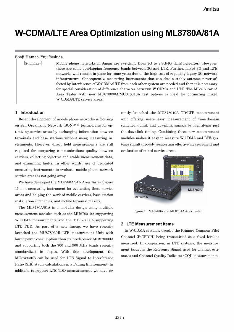
We have developed the ML8780A/81A Area Tester (figure
1) as a measuring instrument for evaluating these service
areas and helping the work of mobile carriers, base station
installation companies, and mobile terminal makers.
The ML8780A/81A is a modular design using multiple
measurement modules such as the MU878010A supporting
W-CDMA measurements and the MU878030A supporting
LTE FDD. As part of a new lineup, we have recently
launched the MU878030B LTE measurement Unit with
lower power consumption than its predecessor MU878030A
and supporting both the 700 and 900 MHz bands recently
standardized in Japan. With this development, the
MU878030B can be used for LTE Signal to Interference
Ratio (SIR) stably calculations in a Fading Environment. In
addition, to support LTE TDD measurements, we have re-
cently launched the MU878040A TD-LTE measurement
unit offering users easy measurement of time-domain
switched uplink and downlink signals by identifying just
the downlink timing. Combining these new measurement
modules makes it easy to measure W-CDMA and LTE sys-
tems simultaneously, supporting effective measurement and
evaluation of mixed service areas.
Figure 1 ML8780A and ML8781A Area Tester
2 LTE Measurement Items
In W-CDMA systems, usually the Primary Common Pilot
Channel (P-CPICH) being transmitted at a fixed level is
measured. In comparison, in LTE systems, the measure-
ment target is the Reference Signal used for channel esti-
mates and Channel Quality Indicator (CQI) measurements.
ML8780A
ML8781A
23
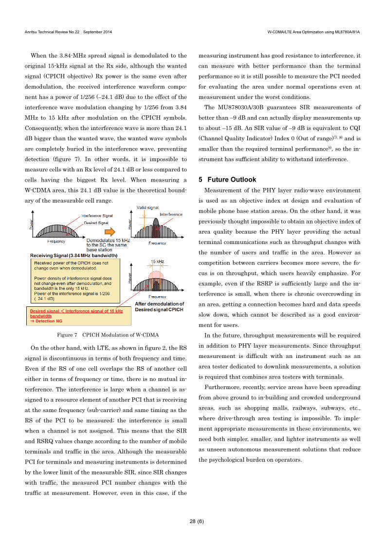
Anritsu Technical Review No.22 September 2014 W-CDMA/LTE Area Optimization using ML8780A/81A
(2)
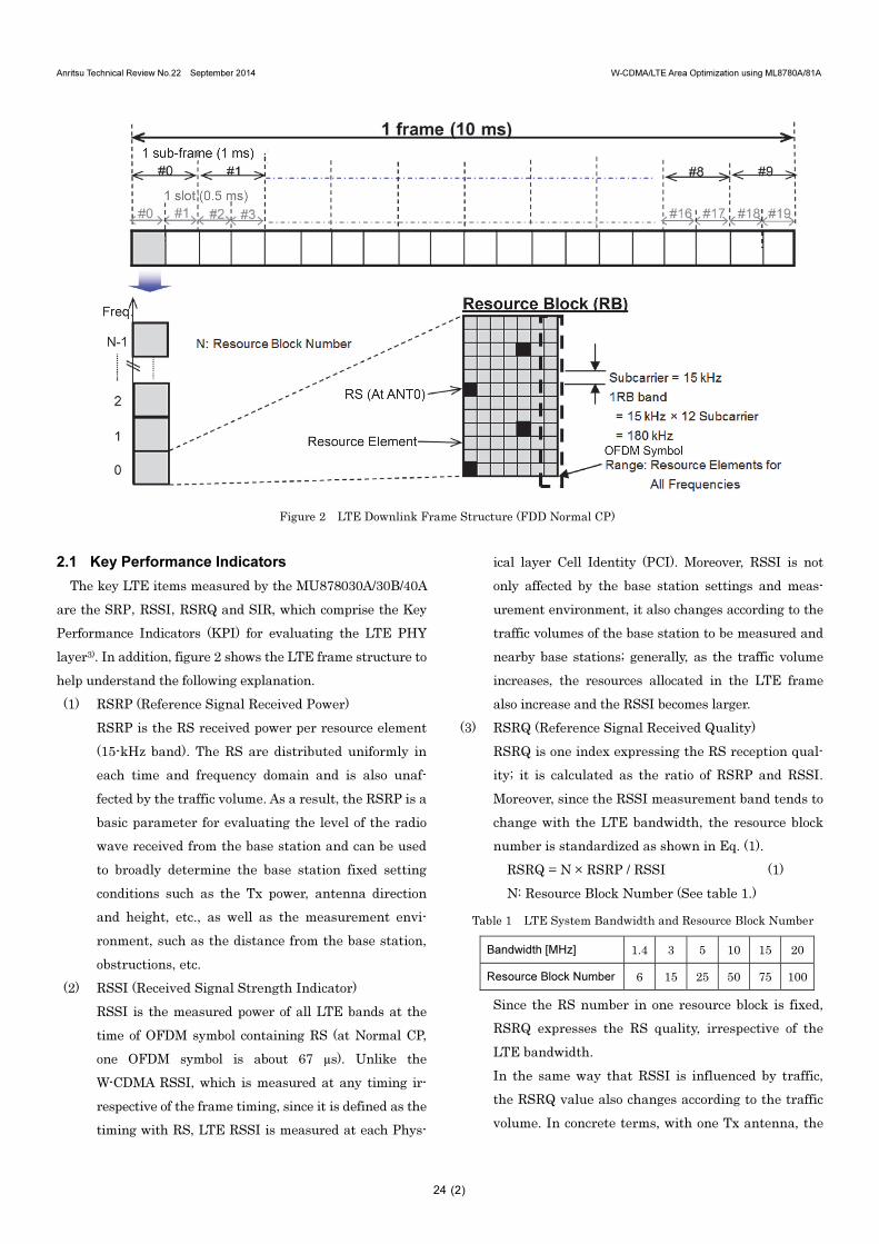
Figure 2 LTE Downlink Frame Structure (FDD Normal CP)
2.1 Key Performance Indicators
The key LTE items measured by the MU878030A/30B/40A
are the SRP,RSSI,RSRQ and SIR, which comprise the Key
Performance Indicators (KPI) for evaluating the LTE PHY
layer3). In addition, figure 2 shows the LTE frame structure to
help understand the following explanation.
(1) RSRP (Reference Signal Received Power)
RSRP is the RS received power per resource element
(15-kHz band). The RS are distributed uniformly in
each time and frequency domain and is also unaf-
fected by the traffic volume. As a result, the RSRP is a
basic parameter for evaluating the level of the radio
wave received from the base station and can be used
to broadly determine the base station fixed setting
conditions such as the Tx power, antenna direction
and height, etc., as well as the measurement envi-
ronment, such as the distance from the base station,
obstructions, etc.
(2) RSSI (Received Signal Strength Indicator)
RSSI is the measured power of all LTE bands at the
time of OFDM symbol containing RS (at Normal CP,
one OFDM symbol is about 67 µs). Unlike the
W-CDMA RSSI, which is measured at any timing ir-
respective of the frame timing, since it is defined as the
timing with RS, LTE RSSI is measured at each Phys-
ical layer Cell Identity (PCI). Moreover, RSSI is not
only affected by the base station settings and meas-
urement environment, it also changes according to the
traffic volumes of the base station to be measured and
nearby base stations; generally, as the traffic volume
increases, the resources allocated in the LTE frame
also increase and the RSSI becomes larger.
(3) RSRQ (Reference Signal Received Quality)
RSRQ is one index expressing the RS reception qual-
ity; it is calculated as the ratio of RSRP and RSSI.
Moreover, since the RSSI measurement band tends to
change with the LTE bandwidth, the resource block
number is standardized as shown in Eq. (1).
RSRQ = N × RSRP / RSSI (1)
N: Resource Block Number (See table 1.)
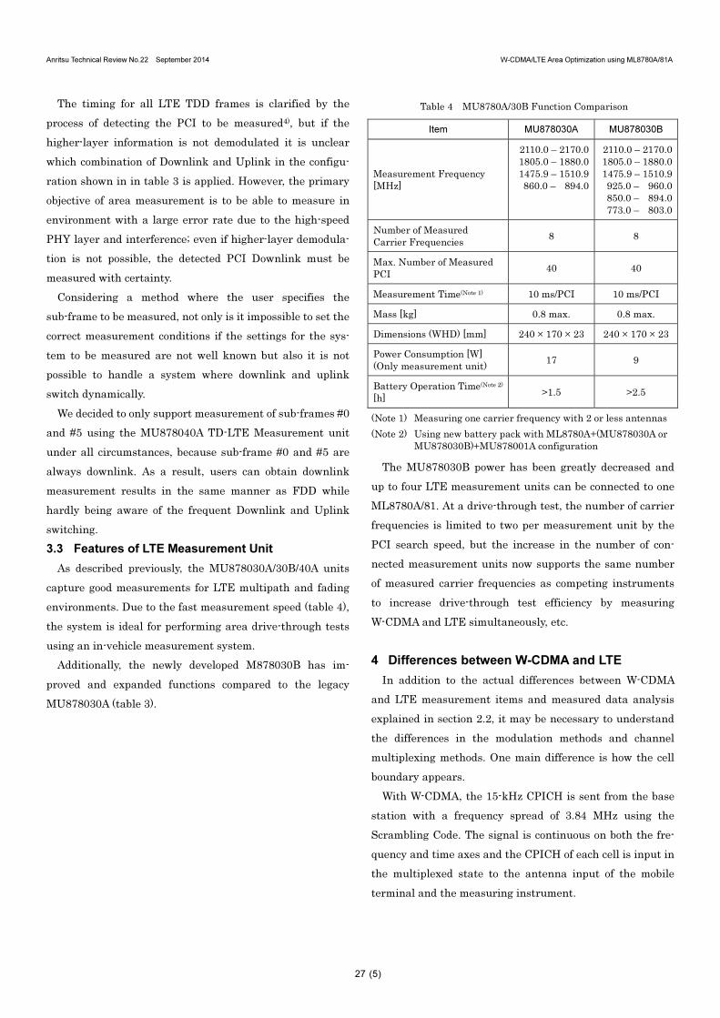
Table 1 LTE System Bandwidth and Resource Block Number
Bandwidth [MHz] 1.4 3 5 10 15 20
Resource Block Number 6 15 25 50 75 100
Since the RS number in one resource block is fixed,
RSRQ expresses the RS quality, irrespective of the
LTE bandwidth.
In the same way that RSSI is influenced by traffic,
the RSRQ value also changes according to the traffic
volume. In concrete terms, with one Tx antenna, the
24
Anritsu Technical Review No.22 September 2014 W-CDMA/LTE Area Optimization using ML8780A/81A
(3)
Maximum value of RSRQ is –3 dB; with two Tx an-
tennas, it is –6 dB (applies when the reference ele-
ments used in the resource block are just RS), and
RSRQ becomes smaller as traffic increases. It also
becomes smaller as interference from neighboring
base stations increases.
(4) SIR (Signal to Interference Ratio)
Like RSRQ, this is one index expressing the RS re-
ception quality. Whereas RSRQ is calculated from the
fraction with denominator RSSI, or in other words
uses the power of the entire band, SIR is calculated
from the fraction whose denominator is just inter-
ference power in the resource block as same as RS’s
resource block 15-kHz band. Since it is difficult to
measure interference power directly, the RS ideal
signal variance is calculated to find the interference
power4). The interference power calculated by this
method is called the Signal to Interference plus Noise
Ratio (SINR) because it includes noise components in
addition to signals from adjacent cells in the same
band. The ML8780A/81A Area Tester displays SIR
without the conventional separation of SIR and
SINR; noise components are included in the SIR
measurement for both W-CDMA and LTE systems.
A feature of SIR is the ability to measure only inter-
ference from other cells (other stations) because it is
unaffected by traffic from the same cell (own station)
as the RS being measured. However, when there are
multipaths with delays exceeding the Cyclic Prefix
(CP), care is required about even signals from the
same cell becoming interference waveforms.
2.2 Comparison of W-CDMA and LTE
Table 2 shows a comparison of W-CDMA and LTE meas-
urement items. It shows that items used to evaluate
W-CDMA areas have LTE equivalents. However, since the
values cannot be compared simply, a different index from the
W-CDMA index must be created to express LTE area quality.
Table 2 W-CDMA/LTE Measurement Comparison
Item W-CDMA LTE Note
Cell Differ-entiation
Scrambling Code (SC)
Physical Cell ID (PCI)
Measurement Target
Common Pilot CH (CPICH)
Reference Signal (RS)
Measurement BandCPICH: 3840 kHz RS: 15 kHz
Measurement Target Rx Power
RSCP [dBm] RSRP [dBm] RSCP and RSRP cannot be compared simply because the measurement target band is different.
Total Rx Power
RSSI [dBm] RSSI, Io [dBm] LTE RSSI cannot be measured when the PCI is not es-tablished.
Proportion to Total Rx Power
Ec/No [dB] RSRQ [dB]
Interference ratio
SIR [dB] SIR [dB] When the wanted (measurement tar-get) and interference wave powers are the same, SIR [dB], the SIR value is: W-CDMA: 24.1Note LTE: 0
(Note) Since W-CDMA SIR is defined in 15-kHz band by dispreading
CPICH, it is handled so that there is gain (256 ⇒ 24.1 dB)
equivalent to the spreading factor for the interference.
3 LTE Measurement Principles and Measurement
Unit Features
3.1 SIR Measurement
Since SIR is hardly affected by own station traffic, SIR
has special importance in evaluating areas with different
overlapping systems like W-CDMA and LTE.
As explained in section 2.1 (4), LTE SIR is calculated from
the demodulated RS symbol variance using the following
equation (4). This is analogous to the SIR measurement
method for W-CDMA5).
RSRP = Iave2 + Qave
2
= {(1/M)ΣIm}2 + {(1/M)ΣQm}2 (3)
Iot = (1/M)・Σ{(Im – Iave)2 + (Qm – Qave)2} (4)
SIR = RSRP / Iot (5)
(Im, Qm): Demodulated RS symbols
M: RS Resource Element Number
However, at actual measurement in the field, the ideal RS
symbol may change on both the frequency and time axes
even when the interference is small, because there are fad-
25
Anritsu Technical Review No.22 September 2014 W-CDMA/LTE Area Optimization using ML8780A/81A
(4)
ing effects due to the occurrence of multipaths and move-
ment of the measuring instrument. Figure 3 shows a simu-
lation of how the RS symbol point for each frequency
(sub-carrier) changes with multipaths and figure 4 plots the
adjacent RS in terms of time at each frequency under the
same multipath effect as shown in figure 3.
Figure 3 Variation in RS Symbol Due to Multipaths (Freq. axis)
The MU878030A/30B/40A uses Eq. (4)' to calculate the
interference power Iot required for the LTE SIR calculation
to reduce the effect of multipaths.
Equation (4)' uses the fact that the difference in the level
changes between adjacent RS is almost constant on the time


![SIMON Data Sheet - NIS Solution | Connecting & Simplifying ...nissolution.com/sites/default/files/SIMON Data Sheet[2].pdf · LTE, WiMAX, CDMA, CDMA- ... Supported Vendors Huawei,](https://static.documents.pub/doc/80x56/5a858efc7f8b9aa5408c96f4/simon-data-sheet-nis-solution-connecting-simplifying-data-sheet2pdflte.jpg)


