19
Wireless Underwater Communications and Networks: Current Achievements and Future Research Challenges Milica Stojanovic Massachusetts Institute of Technology [email protected]
Wireless UnderwaterCommunications and Networks:
Current Achievements and FutureResearch Challenges
Milica Stojanovic
Massachusetts Institute of Technology
Overview
• Introduction
• Channel characteristics
• Signal processing: bandwidth-efficientunderwater acoustic communications
• Underwater networks: channel sharing andmultiple-access
• Future research and open problems
Background
Motivation:• Major scientific discoveries of
the past decade (e.g., hydro-thermal vents): cabledsubmersibles
• Cables are heavy, deployment isexpensive
• Wireless informationtransmission through the ocean:– Remote control of robots,
vehicles– Remote data retrieval
• Wireless communication:– radio (30Hz-300Hz, very high
attenuation)– optical (short distance, pointing
precision)– acoustic
• History:– underwater telephone (analog
modulation, 8-11 kHz).– DSP technology: acoustic
modems (few kbps/few km).• Research growing with new
applications (and vice versa).
Applications: ocean observation
• Environmental monitoring– climate recording– pollution control– prediction of natural disasters– oil/gas fields– harbor protection
• Underwater exploration– discovery of natural resources– marine phenomena– deep-sea archaeology
• Scientific data collection– oceanography– geo-sciences (physics/chemistry)– marine biology
• Search and survey, military and non-military– detection of objects– ocean bottom imaging and
mapping
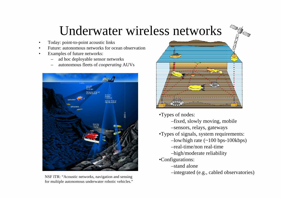
Underwater wireless networks• Today: point-to-point acoustic links• Future: autonomous networks for ocean observation• Examples of future networks:
– ad hoc deployable sensor networks– autonomous fleets of cooperating AUVs
•Types of nodes:–fixed, slowly moving, mobile–sensors, relays, gateways
•Types of signals, system requirements:–low/high rate (~100 bps-100kbps)–real-time/non real-time–high/moderate reliability
•Configurations:–stand alone–integrated (e.g., cabled observatories)
NSF ITR: “Acoustic networks, navigation and sensingfor multiple autonomous underwater robotic vehicles.”
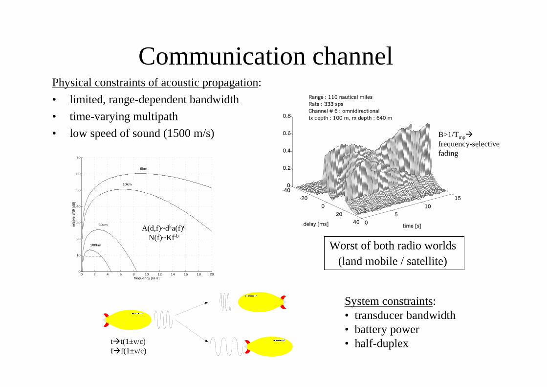
Communication channelPhysical constraints of acoustic propagation:
• limited, range-dependent bandwidth
• time-varying multipath
• low speed of sound (1500 m/s)
System constraints:• transducer bandwidth• battery power• half-duplex
Worst of both radio worlds(land mobile / satellite)
0 2 4 6 8 10 12 14 16 18 200
10
20
30
40
50
60
70
5km
10km
50km
100km
frequency [kHz]
rela
tive
SN
R [d
B]
t�t(1±v/c)f�f(1±v/c)
A(d,f)~dka(f)d
N(f)~Kf-b
B>1/Tmp�frequency-selectivefading
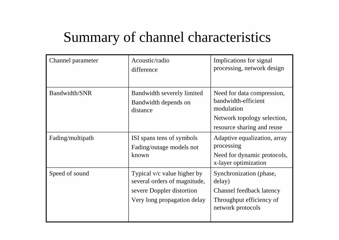
Summary of channel characteristics
Synchronization (phase,delay)
Channel feedback latency
Throughput efficiency ofnetwork protocols
Typical v/c value higher byseveral orders of magnitude,
severe Doppler distortion
Very long propagation delay
Speed of sound
Adaptive equalization, arrayprocessing
Need for dynamic protocols,x-layer optimization
ISI spans tens of symbols
Fading/outage models notknown
Fading/multipath
Need for data compression,bandwidth-efficientmodulation
Network topology selection,
resource sharing and reuse
Bandwidth severely limited
Bandwidth depends ondistance
Bandwidth/SNR
Implications for signalprocessing, network design
Acoustic/radio
difference
Channel parameter
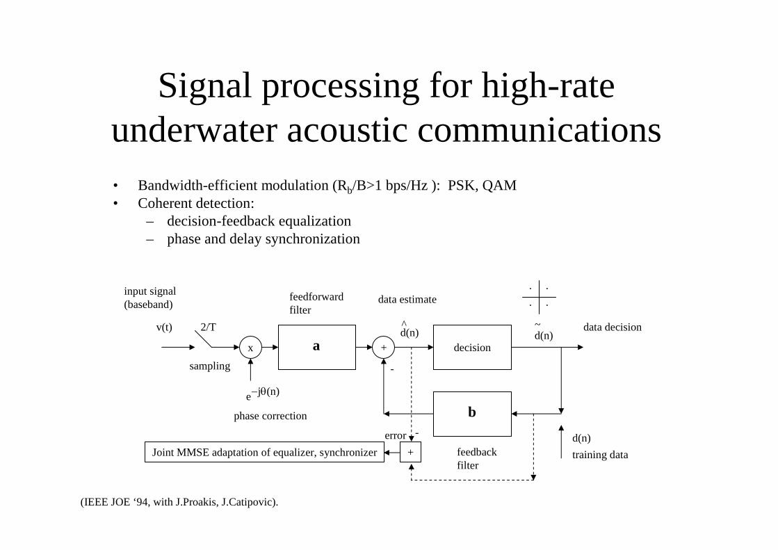
Signal processing for high-rateunderwater acoustic communications• Bandwidth-efficient modulation (Rb/B>1 bps/Hz ): PSK, QAM• Coherent detection:
– decision-feedback equalization– phase and delay synchronization
(IEEE JOE ‘94, with J.Proakis, J.Catipovic).
x + decisiona
b
v(t) 2/T d(n)^
d(n)~
d(n)
training data
-
e−jθ(n)
data decision
data estimate
sampling
phase correction
feedforwardfilter
feedbackfilter
input signal(baseband)
.
..
.
Joint MMSE adaptation of equalizer, synchronizer +
-error
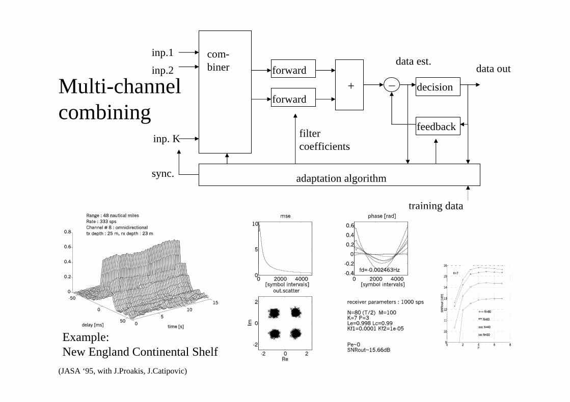
inp. K
com-biner forward
forward+ _ decision
feedback
adaptation algorithm
inp.1
inp.2 data out
sync.
filtercoefficients
training data
data est.
Multi-channelcombining
Example:New England Continental Shelf
(JASA ‘95, with J.Proakis, J.Catipovic)
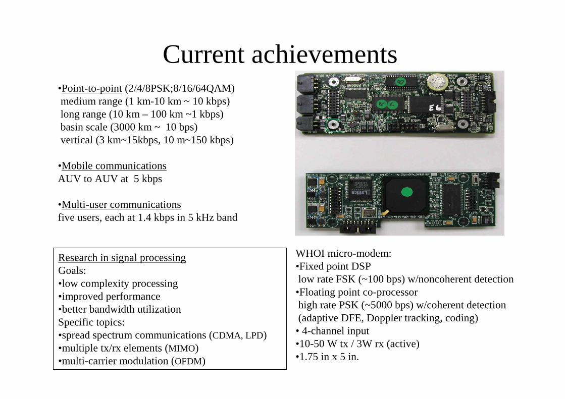
Current achievements•Point-to-point (2/4/8PSK;8/16/64QAM)medium range (1 km-10 km ~ 10 kbps)long range (10 km – 100 km ~1 kbps)basin scale (3000 km ~ 10 bps)vertical (3 km~15kbps, 10 m~150 kbps)
•Mobile communicationsAUV to AUV at 5 kbps
•Multi-user communicationsfive users, each at 1.4 kbps in 5 kHz band
WHOI micro-modem:•Fixed point DSPlow rate FSK (~100 bps) w/noncoherent detection•Floating point co-processorhigh rate PSK (~5000 bps) w/coherent detection(adaptive DFE, Doppler tracking, coding)• 4-channel input•10-50 W tx / 3W rx (active)•1.75 in x 5 in.
Research in signal processingGoals:•low complexity processing•improved performance•better bandwidth utilizationSpecific topics:•spread spectrum communications (CDMA, LPD)•multiple tx/rx elements (MIMO)•multi-carrier modulation (OFDM)
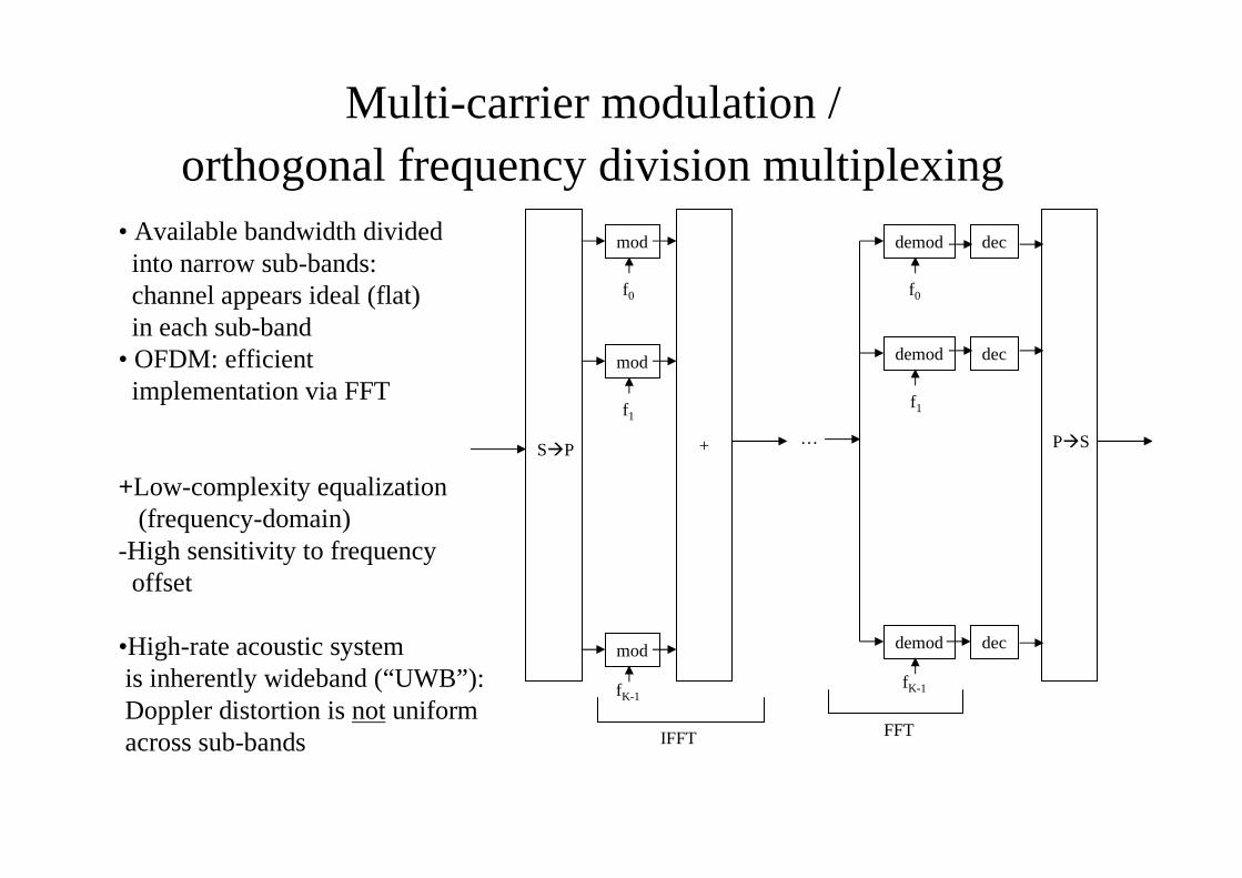
Multi-carrier modulation /orthogonal frequency division multiplexing
• Available bandwidth dividedinto narrow sub-bands:channel appears ideal (flat)in each sub-band
• OFDM: efficientimplementation via FFT
+Low-complexity equalization(frequency-domain)
-High sensitivity to frequencyoffset
•High-rate acoustic systemis inherently wideband (“UWB”):Doppler distortion is not uniformacross sub-bands
f0
f1
fK-1
mod
mod
mod
S�P +
IFFT
demod
f0
dec
demod
f1
dec
demod
fK-1
dec
P�S…
FFT

0 10 20 30
−2
0
2
4
top: subchannel K−1bottom: subchannel 0
phase estimates [rad]
block index
0 10 20 30
−4
−2
0
2
x 10−5
block index
a−estimate
0 500 10000
0.2
0.4
0.6
0.8
1
subchannel index
channel estimates (abs.)
System parameters:
M=12 receiver elements
K=1024 subchannels (32 blocks)
no overlap add
pilot channels: 0
phase difference filtering: 0
channel tracking: 0.99
MSE: −16.3 dB
SER: 0
−2 −1 0 1 2−2
−1
0
1
2
Re
Im
output scatter plot
0 10 20 30−30−20−10
0
block index
MSE−time [dB]
0 200 400 600 800 1000−30−20−10
0
subchannel index
MSE−frequency [dB]
FFT
FFT
combiner
combiner
.
.
.
.
.
.
in 1
in M
1
K
1
K
dec
dec
out 1
out K
Experiment:Buzzards Bay ‘05
Adaptive channel tracking,Doppler compensation (v/c)
30+ kbps / 2.5 km@ minimal complexity
(work in progress; IEEE Oceans ‘06)

Future autonomous underwatersystems: network topologies
• Centralized • Decentralized
Nodes communicate via a central station (cellular networkparadigm).
Channel must be shared—regulation of multiple access.
Central stations are connected through a separateinfrastructure (cable on the bottom, radio on the surface).
Nodes communicate through neighbors (ad hoc networkparadigm).
Messages must be relayed to reach destination—regulation ofchannel access.
There may be an end node to gateway. Nodes may form clusters.
Open problems (There are no operational autonomous underwater networks, only isolated experimental demonstrations):
Capacity of an acoustic network? (Energy and bandwidth depend on inter-node distance.)
Efficient and scalable channel sharing protocols? (Speed of sound is five orders of magnitude less than speed of electro-magnetic waves.)
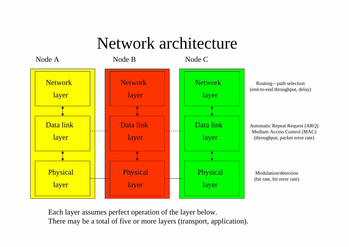
Network architecture
Each layer assumes perfect operation of the layer below.There may be a total of five or more layers (transport, application).
Network
Physical
Data link
layer
layer
layer
Network
Physical
Data link
layer
layer
layer
Network
Physical
Data link
layer
layer
layer
Node A Node B Node C
Routing—path selection(end-to-end throughput, delay)
Automatic Repeat Request (ARQ)Medium Access Control (MAC)(throughput, packet error rate)
Modulation/detection(bit rate, bit error rate)
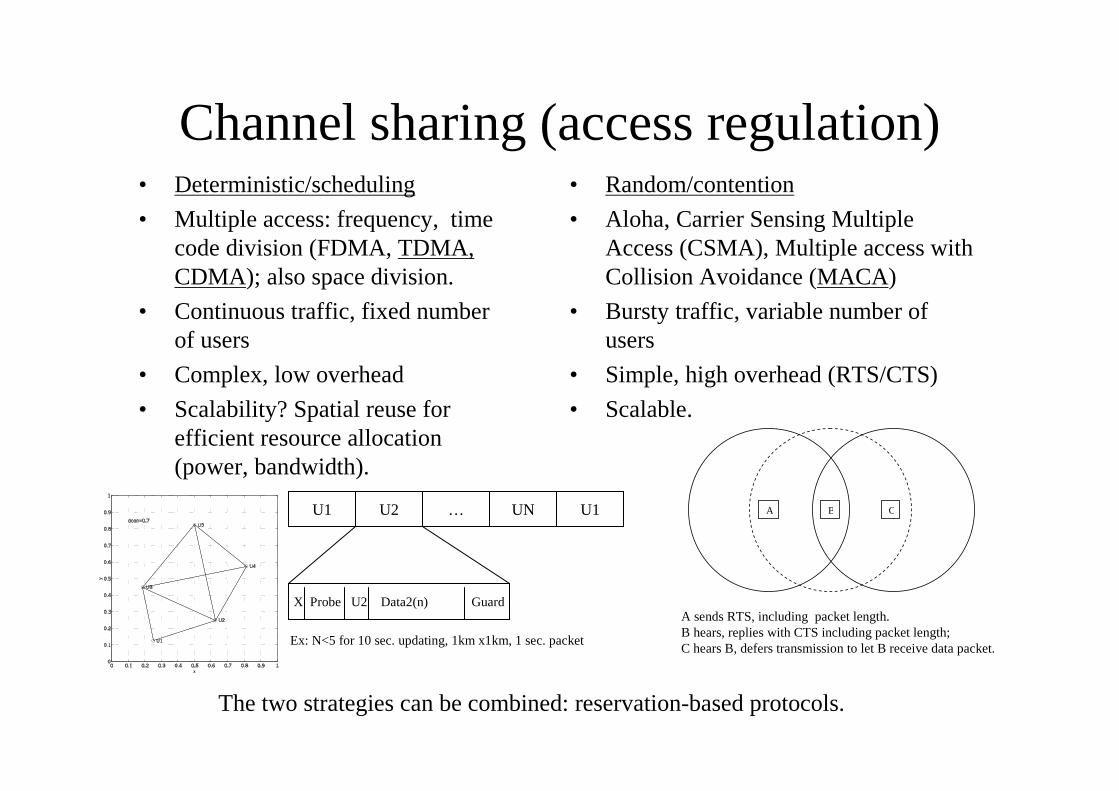
Channel sharing (access regulation)• Deterministic/scheduling
• Multiple access: frequency, timecode division (FDMA, TDMA,CDMA); also space division.
• Continuous traffic, fixed numberof users
• Complex, low overhead
• Scalability? Spatial reuse forefficient resource allocation(power, bandwidth).
• Random/contention
• Aloha, Carrier Sensing MultipleAccess (CSMA), Multiple access withCollision Avoidance (MACA)
• Bursty traffic, variable number ofusers
• Simple, high overhead (RTS/CTS)
• Scalable.
The two strategies can be combined: reservation-based protocols.
U1 U2 … UN U1
X Probe U2 Data2(n) Guard
BA C
Ex: N<5 for 10 sec. updating, 1km x1km, 1 sec. packet
A sends RTS, including packet length.B hears, replies with CTS including packet length;C hears B, defers transmission to let B receive data packet.
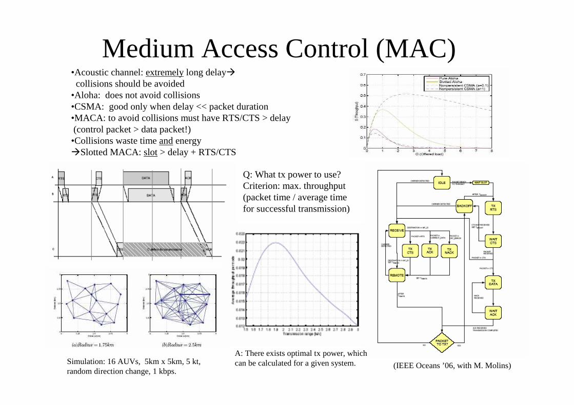
Medium Access Control (MAC)•Acoustic channel: extremely long delay�collisions should be avoided
•Aloha: does not avoid collisions•CSMA: good only when delay << packet duration•MACA: to avoid collisions must have RTS/CTS > delay(control packet > data packet!)•Collisions waste time and energy�Slotted MACA: slot > delay + RTS/CTS
Q: What tx power to use?Criterion: max. throughput(packet time / average timefor successful transmission)
Simulation: 16 AUVs, 5km x 5km, 5 kt,random direction change, 1 kbps.
A: There exists optimal tx power, whichcan be calculated for a given system. (IEEE Oceans ’06, with M. Molins)
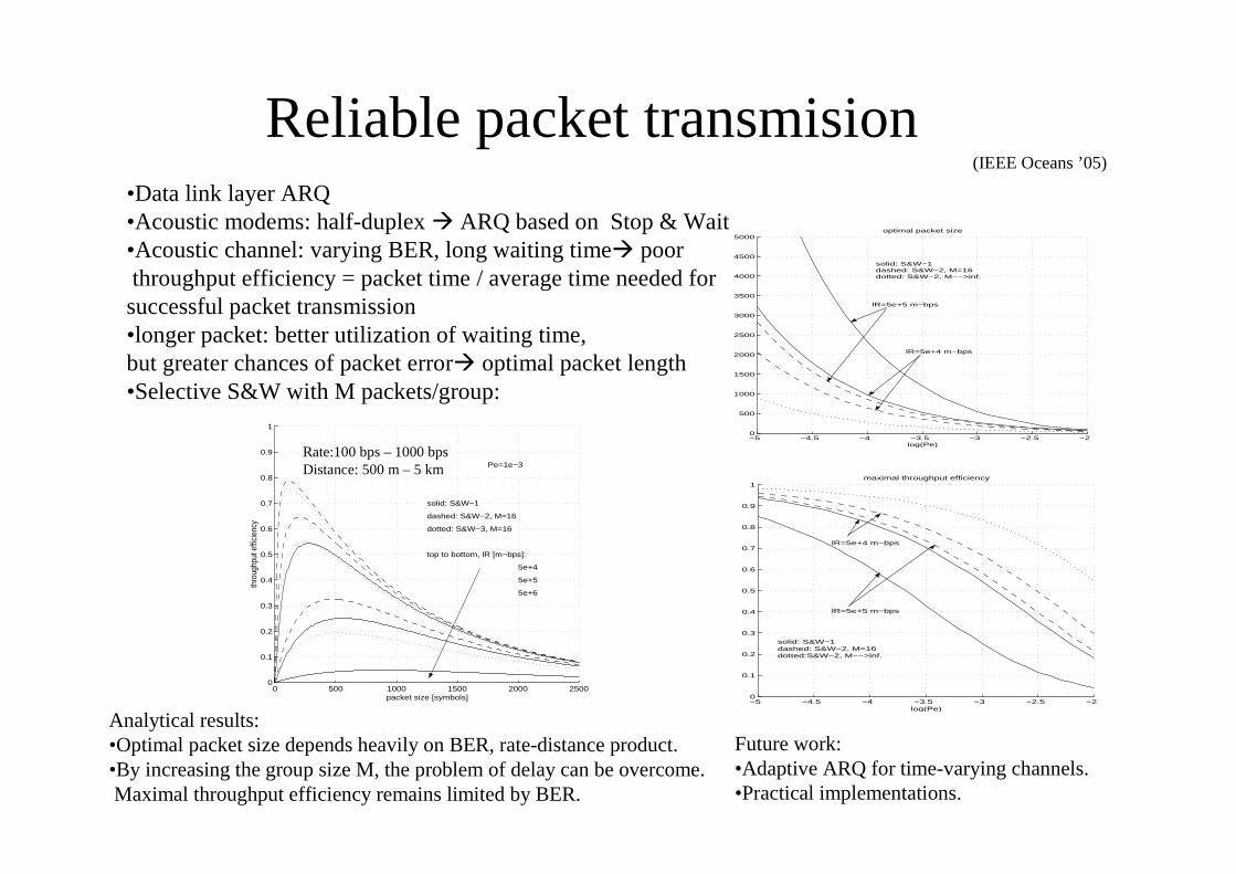
Reliable packet transmision•Data link layer ARQ•Acoustic modems: half-duplex � ARQ based on Stop & Wait•Acoustic channel: varying BER, long waiting time� poorthroughput efficiency = packet time / average time needed forsuccessful packet transmission•longer packet: better utilization of waiting time,but greater chances of packet error� optimal packet length•Selective S&W with M packets/group:
0 500 1000 1500 2000 25000
0.1
0.2
0.3
0.4
0.5
0.6
0.7
0.8
0.9
1
Pe=1e−3
solid: S&W−1
dashed: S&W−2, M=16
dotted: S&W−3, M=16
top to bottom, lR [m−bps]:
5e+4
5e+5
5e+6
packet size [symbols]
thro
ughp
ut e
ffici
ency
−5 −4.5 −4 −3.5 −3 −2.5 −20
500
1000
1500
2000
2500
3000
3500
4000
4500
5000
log(Pe)
optimal packet size
solid: S&W−1dashed: S&W−2, M=16dotted: S&W−2, M−−>inf.
lR=5e+5 m−bps
lR=5e+4 m−bps
Rate:100 bps – 1000 bpsDistance: 500 m – 5 km
−5 −4.5 −4 −3.5 −3 −2.5 −20
0.1
0.2
0.3
0.4
0.5
0.6
0.7
0.8
0.9
1
log(Pe)
maximal throughput efficiency
solid: S&W−1dashed: S&W−2, M=16dotted:S&W−2, M−−>inf.
lR=5e+5 m−bps
lR=5e+4 m−bps
Analytical results:•Optimal packet size depends heavily on BER, rate-distance product.•By increasing the group size M, the problem of delay can be overcome.Maximal throughput efficiency remains limited by BER.
Future work:•Adaptive ARQ for time-varying channels.•Practical implementations.
(IEEE Oceans ’05)
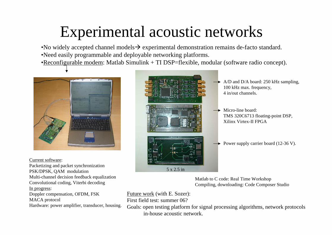
Experimental acoustic networks•No widely accepted channel models� experimental demonstration remains de-facto standard.•Need easily programmable and deployable networking platforms.•Reconfigurable modem: Matlab Simulink + TI DSP=flexible, modular (software radio concept).
Current software:Packetizing and packet synchronizationPSK/DPSK, QAM modulationMulti-channel decision feedback equalizationConvolutional coding, Viterbi decodingIn progress:Doppler compensation, OFDM, FSKMACA protocolHardware: power amplifier, transducer, housing.
A/D and D/A board: 250 kHz sampling,100 kHz max. frequency,4 in/out channels.
Micro-line board:TMS 320C6713 floating-point DSP,Xilinx Virtex-II FPGA
Power supply carrier board (12-36 V).
5 x 2.5 in
Matlab to C code: Real Time WorkshopCompiling, downloading: Code Composer Studio
Future work (with E. Sozer):First field test: summer 06?Goals: open testing platform for signal processing algorithms, network protocols
in-house acoustic network.
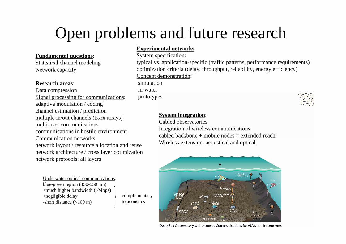
Open problems and future researchFundamental questions:Statistical channel modelingNetwork capacity
Research areas:Data compressionSignal processing for communications:adaptive modulation / codingchannel estimation / predictionmultiple in/out channels (tx/rx arrays)multi-user communicationscommunications in hostile environmentCommunication networks:network layout / resource allocation and reusenetwork architecture / cross layer optimizationnetwork protocols: all layers
Experimental networks:System specification:typical vs. application-specific (traffic patterns, performance requirements)optimization criteria (delay, throughput, reliability, energy efficiency)Concept demonstration:simulationin-waterprototypes
Underwater optical communications:blue-green region (450-550 nm)+much higher bandwidth (~Mbps)+negligible delay-short distance (<100 m)
System integration:Cabled observatoriesIntegration of wireless communications:cabled backbone + mobile nodes = extended reachWireless extension: acoustical and optical
complementaryto acoustics


