These operating instructions apply to the following product:
Type: The Weightanka® System Compatibility The Weightanka system can be used with PPE according to;
• EN 354: 2002 (fixed lanyards). • EN 355: 2002(energy absorbing device). • EN 360: 2002 (retractable): always consult the manufacturer of the PPE to affirm
that it can be used in the horizontal configuration and over the edge of any potential drop.
• EN 361: 2002 (safety harness), subject to strict adherence to the manufacturer’s instructions for use.
• Guided Type fall Arrest system to EN 353-2 and EN358.
CAUTION! As there is the possibility of the system having to arrest a fall, means of dissipating energy (e.g. a device or system to EN355) should be incorporated to keep the maximum impact force to below 6 KN. EN355 devices are tested using a 100 kg standard, users who exceed this (including equipment carried) should consult the manufacturer of the energy dissipation system to confirm the suitability of such a product.
Health and Safety Installers and users must comply with all relevant health and safety regulations. In the U.K., particular attention should be drawn to the H.S.E. publication: INDG 284 – Working on roofs.
U.K. based installers/ users may obtain copies of the above publication – free of charge – from their Health and Safety Executive area office.
Introduction 0-3 of 8
Familiarisation
WARNING! Before using Weightanka for the first time, it is strongly recommended that users familiarise themselves with the product, these instructions, the terms used to describe the various parts and the marking on the product. It is essential that users fully understand these before using Weightanka at the worksite.
Certifying Body Identification No.: 0320 Address: National Engineering Laboratory
East Kilbride, Glasgow. G75 0QU, United Kingdom
Anticipated Life Metal Components & Rubber Pads: Up to 25 years in non-marine, non-corrosive (e.g. chemical
plant) environments with a temperature range from –10 to + 40 degrees centigrade subject to use and inspection strictly in accordance with these instructions.
Storage and Components
l These Operating instructions form a component part of The Weightanka system. They must accompany the system and be followed for use.
l At no time must any pages be removed from these instructions. If the instructions are lost in their entirety or in part, the instructions or the missing parts must be replaced immediately. Please contact your supplier or the manufacturer
Copyright
This documentation contains information protected by copyright. It may not be photocopied, reproduced, translated or recorded on data media, either completely or as extracts, without prior permission.
We reserve all further rights.
Introduction 0-4 of 8
Amendment Service
This document is not subject to any amendment service from the manufacturer. Amendments to this documentation can be carried out without prior notice.
Modifications to The Weightanka system
If you undertake modifications to the Weightanka system, you will negate all certification that comes with this product! As a result, the declaration of conformity that you have received with The Weightanka system will be deemed as null and void.
In this case, you must have all component parts of the system re-assessed for conformity in accordance with the applicable product guidelines and National Legislation.
Use In Accordance With Regulations And Incorrect Use
Contents
The use in accordance with regulations and incorrect use are described below.
Definition "Authorised Person"
A person is deemed to be an authorised person if they have been authorised to work on or with the Weightanka system in accordance with these instructions.
Use in Accordance With Regulations The Weightanka system is a mobile deadweight anchor system. It is a component part of a personal protection system for the prevention of falls from heights and may be used only in conjunction with the relevant personal protective equipment (Lanyards etc.)- See section 0.2 “Compatibility” – page 0-2. The user must seek guidance from, and follow the instructions supplied by, the manufacturer of such equipment. The Weightanka system is deemed to be used in accordance with regulations only when all the following conditions are met.
l For use in fall arrest situations, only one person may be connected to The Weightanka system at any time.
l Where the combination of the Weightanka position and the PPE supplied ensures that no user is able to reach a position within 0.5 metres of any roof edge, roof opening or other fall hazard (i.e. use as fall RESTRAINT only), a maximum of two users may be connected simultaneously.
l All users must be equipped with a means of ensuring that the forces applied to the body (and therefore to the anchor device) during the arrest of a fall does not exceed 6kN. Where the weight of the user, with clothing, personal protective equipment and, if necessary, tools, may exceed 100 kg. when secured to the system, it should be ascertained that the 6kN maximum force will not be exceeded (by reference to the manufacturer of the energy absorber or other force limiting equipment).
Introduction 0-5 of 8
l The potential danger that arises when The Weightanka system is used in conjunction with fall arrest equipment to EN 360, or energy absorbing devices (to EN 355) must be assessed.
Important: Read the notes on page 2-16 l All component parts must be used for the assembly of the system .The number of weights
necessary for the various types of roof surfaces on which the Weightanka system may be installed are shown on page 2-11. The total number of weights used to assemble the Weightanka system must at all times be in accordance with the table on page 2-11.
l No part of The Weightanka system is to be placed closer than 2.5 metres from the edge of a roof or open void or any other fall hazard.
l A clearance height of at least 250 mm must remain above the highest component of the system.
l The Weightanka system is designed only for use on roofs of the types shown on page 2-11, with a maximum slope of the roof surface of 5°.
l The Weightanka system may only be used when the supporting base is free from snow and ice. Do not use if there is the risk of frost or in freezing conditions.
l Do not position The Weightanka system where there is a risk of accumulation of water or where there is contamination of the roof surface and / or any Weightanka component by oil, grease or growth of algae
l Use of Weightanka in high winds is not permitted.
l Ensure that all fragile roof lights in the work area are covered to prevent falls through them.
Repeat: Only use The Weightanka system when all conditions are met ! Your l i fe depends on i t !
Incorrect Use
The following conditions are classified as incorrect use:
l The use of The Weightanka system when one of the conditions listed under "use in accordance with regulations" is not met.
l The failure to observe the minimum distances, number of weights and conditions imposed on the supporting base listed in "use in accordance with regulations". The Weightanka system may move in the case of the attached person falling. If the listed conditions are not observed, the system may possibly move too much and fall from the roof.
l The use of a damaged, incomplete or incorrectly assembled Weightanka system.
l Use for securing horizontal line systems. (A purpose designed deadweight anchor system “Wireanka” is available for this purpose).
l Use as an anchor for access by rope or for abseiling. (A purpose designed deadweight anchor system “Accessanka” is available for this purpose).
l Use by an operative without prior instruction by a competent, trained person.
Introduction 0-6 of 8
l Working in the vicinity of fragile roof lights without covering them to prevent falls through them. (A purpose made freestanding guardrail solution “Kee Dome” is available for this purpose.
Use of The Weightanka system in any of the above conditions is forbidden. If the system is used incorrectly, a fatal fall or severe injuries may occur.
Operator's Duty of Care
Contents
The duties and obligations of the operator and trained personnel when dealing with The Weightanka system are set out below.
Safety of The Weightanka system
The operator or trained personnel must ensure that The Weightanka system:
l is used only in accordance with Health and Safety regulations,
l is made available for use only in a proper, functional state. l is used in accordance with the regulations set out herein.
l is checked regularly,
l is used only by qualified, trained and authorised personnel.
Protection of Personnel
All persons using the system must ensure that the necessary personal protective equipment:
l is available for use and IS USED (See Compatibility Page 0-2)
l is checked regularly and the check recorded
l IMPORTANT! Wear suitable protective footwear to avoid injury to the feet in case any of the component parts are dropped or fall on to them.
Instruction and Training
All users of the system must ensure that:
• Before using the system for the first time and at least once annually thereafter, all personnel shall be instructed in all relevant matters of health and safety at work (with particular emphasis on Working at Height) and environmental protection,
Introduction 0-7 of 8
• The operating instructions are always available in a legible state, are complete and are kept with the system at all times.
• All users are familiar with the contents of these operating instructions.
Personnel Requirements
Contents
The requirements the manufacturer places on the users of The Weightanka system are as follows:
Duties of the User
The user must fulfil the following duties:
• Operate The Weightanka system strictly in accordance with these instructions and check that it is functioning correctly and safely.
• Recognise and - as far as possible and permissible – repair any damage to the system, or, if repair is not possible, immediately withdraw the system from use and return the system to the manufacturer for repair.
Requirements of the User
In order to be able to fulfil his or her duties, the user must meet the following requirements:
• They must have received instruction from a trained operator of the system.
• They must have adequate knowledge of the English language to understand these operating instructions.
• They must be free from any disability that may affect their ability to use this system or understand these instructions.
• It is unlikely that any medical condition may directly affect (or be affected by) the use of this product in itself, but users must be aware that:
• Working at height is a dangerous occupation. They should be trained to do so, and should comply with any medical requirements set by the training provider.
• The manufacturer or supplier of PPE to be used with this product may impose medical requirements on users of their products, which must be complied with.
Definition "Trained Person"
Trained persons, are persons who, based on their specialist training and experience have adequate knowledge of the system to be checked and are sufficiently familiar with the relevant regulations, guidelines and generally recognised rules of the Weightanka system and accompanying regulations - e.g., Health and Safety Regulations and Accident Prevention
Introduction 0-8 of 8
Regulations that are in force in the country of use; and can assess the safe working conditions of the installation location.
A trained person shall be responsible for selecting all users of The Weightanka system.
For Your Safety 1-1 of 4
Chapter 1 For Your Safety
1.1 Summary
l Important Information!
l The following safety information is to be understood as being in addition to any existing Health and Safety Regulations and laws already in force.
l Existing accident prevention regulations and laws must be observed in all cases.
Summary
This chapter is split into the following subjects:
Subject Page
Symbols 1-2
Basic Safety Instructions 1-3
For Your Safety 1-2 of 4
1.2 Symbols
Contents
An Explanation of the symbols used follows.
Danger!
This symbol indicates that there is a risk to the life and safety of people.
Where life is endangered, the wording "Danger to Life" shall be indicated separately.
Attention!
This symbol indicates that there is a threat of damage to goods or to the environment.
Advice!
This symbol identifies information that contributes to the better understanding of the Weightanka system.
For Your Safety 1-3 of 4
1.3 Basic Safety Instructions
Contents
Basic safety instructions for the safe handling of the Weightanka system can be found here.
Danger!
It is imperative that you follow these safety instructions to avoid endangering your life and safety:
Possible Danger Measures for Avoidance
Danger to Life! Risk of the user falling as a result of incorrect use.
Explanation: Falls resulting in death or severe injuries can result from the incorrect use of the Weightanka system.
l Use the Weightanka system only as described in the operating instructions.
l Before use, check all components and connector parts for correct positioning.
l Ensure that the correct number of weights for the type of roof surface (see page 2-11) has been used.
l Check for any damaged parts.
Danger to Life! Danger of the user falling as the result of an inappropriate installation site.
Explanation: An inadequate supporting base or assembly on type of roof surface not approved for use with this product (see page 2-11.) can lead to the Weightanka system either slipping or falling - particularly if the user falls.
l Pay attention to the detailed instructions concerning the installation site, assembly and use of the Weightanka system in Chapter 2 of these user instructions.
l The supporting base must always have the specified characteristics and load-bearing capacity.
l The specified masses and number of weights must be observed in all cases.
l A risk assessment of the workplace must be carried out before use in all cases.
For Your Safety 1-4 of 4
Danger to Life! Danger of the user falling as a result of defective or inadequate maintenance.
Explanation: Defects or damage relevant to safety can adversely affect the functionality of the Weightanka system. In these circumstances the safe functioning of the system is not assured.
l Before use, check Weightanka for damage.
l Damaged parts must be replaced before use in all cases. Only after this may the Weightanka system be used!
l In case of doubt change the equipment
l In case of a fall change the equipment
Using Weightanka 2-1 of 28
Chapter 2 Using the Weightanka system
Summary This chapter is split into the following subjects:
Subject Page
Transporting and Storing the Weightanka system 2-2
Checking the Component parts 2-3
Selecting the Installation Site 2-11
Number of Weights & Positioning the Weightanka 2-13
Establishing Fall Arrest Distance 2-14
Using the Weightanka system 2-16
Maintenance, Inspection and Disposal 2-19
Labels 2-24
Using Weightanka 2-2 of 28
Transporting and Storing the Weightanka system
Contents
Instructions for the safe transportation of the Weightanka system.
Danger! Pack, store and transport Weightanka so that the rubber bases and the eye for connecting the safety harness cannot be damaged.
Packing We recommend the component parts are packed in a wooden crate or shrunk wrapped onto a pallet for transportation. In the case of transport by sea, the packing must be impervious to seawater.
Transportation There are no restrictions to the means of transport.
Storage
Longer-term storage must be under cover for protection against the weather.
All component parts must be stored on a flat surface to minimise any potential risk of damage.
Using Weightanka 2-3 of 28
Checking the component parts
Contents The following is a review of all parts needed for the correct assembly of the Weightanka system
Danger! If all the parts shown in Figure 1 are not present or if parts are damaged, they must be replaced by original parts. Contact your supplier or the manufacturer for advice.
Using Weightanka 2-4 of 28
Names and Functions of the Necessary Component Parts
Figure 1
Weight Locating Pin DW1016010
Standard Weight DW1012010
Bottom Cross Arm DW1015B10
Top Cross Arm DW1015T10
Class A1 M12 X 75 Eye-Bolt EN0075G10 PPE Warning disc PP00FA040 or PP00FR040 Sealing Washer PWH003840
Pedestal DW1018010 Secured with M20 x 25 CSK Screw DWM207570
Rubber Coated Base Weights DW1013010
Stabiliser Arm DW1014010
Securing R Clip DWACLP010
Using Weightanka 2-5 of 28
The component parts depicted previously have the following names and functions:
Item Name Function Quantity
DWA1016010 Weight Locating Pin • Locates the position of the standard weights
• The locating pins screw into the central tapped hole of each rubber coated base weight.
• Four drilled holes are provided at the top (unthreaded) end of the pin. Insert the securing pin into the lowest possible hole according to the number of weights being used.
• Total weight of 4 weight locating pins = 1.30 Kg
4 pieces
DWA1013010 Rubber Coated Base Weights • Base plates to provide maximum friction and / or adhesion with the roof surface
• It is important that the Rubber Coated Base Weights are installed with the suction cups facing down, in direct contact with the surface
• It is important that the rubber suction cups are maintained undamaged and free from contaminations such as oil, grease or algae.
• Each rubber coated base weight has a central tapped hole to accept the weight Locating Pin
• Total weight of 4 Rubber Coated Base Weights = 68 Kg
4 pieces
PWH003840
Polythene Washer • Positioned between the warning disc and the pedestal.
1 piece
Using Weightanka 2-6 of 28
DW1015B010 Bottom Cross Arms • To attach the base weights Length = 1600 mm;
Bottom cross arm has threaded spreader plate to accept the pedestal fixing bolt.
• The bottom cross arm has a second tapped hole and spreader plate which is only utilised when the Weightanka is used in conjunction with Kee Anchor Accessanka
• The weight of the bottom cross
arm is 16 kg
1 piece
Threaded Spreader Plate • The threaded spreader plate is supplied welded to the bottom cross arm. The socket screw is screwed through the spreader plate, to attach the central pedestal
1 Piece
DWM207570 Zinc plated Socket Screw • Used to attach the central pedestal to the cross arm assembly.
• The socket screw is screwed through the bottom cross arm such that it passes through the spreader plate BEFORE passing through the bottom cross arm, and such that the countersunk head of the socket screw seats into the countersunk section of the spreader plate.
• Weight of 1 socket screw is 0.2 Kg.
1 piece
Using Weightanka 2-7 of 28
DW1015T10 Top Cross Arm • To attach the base weights Length = 1,600 mm;
Top cross arm does NOT have threaded spreader plate to accept the pedestal fixing bolt.
• The weight of the top cross arm is 15 kg
1 piece
PP00FA040
OR
PP00FR040
PPE Warning Disc • Disc to provide information on use and date of test.
• Positioned under the eyebolt and above the polythene washer.
1 piece
DW1018010 Central Pedestal • The central pedestal provides a raised position for the attachment point, thus increasing the performance of the system
• The lower end of the central pedestal has an M20 threaded hole to accept the socket screw
• The upper end of the pedestal has an M12 tapped hole to accept the class A1 eyebolt used as the attachment point.
• Weight of central pedestal = 2.5 Kg.
1 piece
Using Weightanka 2-8 of 28
DW1012010 Standard Weights • The standard weights are Galvanised and have a bright silver appearance. They should not be confused with the Base weights which are rubber coated and black in appearance
• The central hole of the standard weights is un-threaded, and designed to accept the unthreaded portion of the Weight locating pin
• Either six, eight or twelve standard weights are required to assemble a Weightanka (R) system, depending on the type of roof surface. It is IMPERATIVE that the correct number of standard weights is employed. See section 2.5 Page 11.
• Total weight of 4 standard weights = 100 Kg
• Total weight of 6 standard weights = 150 kg
6, 8 OR 12 pieces
EN0075G10 Class ‘A1’ Anchor device (M12 Eyebolt)
• An M12 threaded eyebolt, screwed into the top of the central pedestal to which the user’s personal protection system (e.g. lanyard) must be attached
• Weight of 1 M12 class A1 anchor device = 0.2 Kg
1 Piece
Using Weightanka 2-9 of 28
DWACLP010 Securing Pins (‘R’ clips) • ‘R’ clip type securing pins used to prevent accidental release of the standard weights from the Weight Locating Pins.
• The securing pins are fitted after all necessary standard weights have been fitted ( See section 2.5 Page 11 )
• Fit the securing pins into the first visible hole of the weight locating pin nearest to the top standard weight
• Weight of 4 securing pins = 0.15 kg.
4 pieces
DWATBAR10 Tommy Bar • For use when tightening the eyebolt into the pedestal
• The length and diameter of the tommy bar is specially designed to apply the correct force when tightening the eyebolt
• The tommy bar should ONLY be used with the eyebolt centrally positioned and with one hand turning each end.
• NEVER use the tommy bar with the eyebolt positioned at one end as this would result in too much force being applied which could damage the eyebolt.
• Weight of 1 tommy bar = 0.35 Kg.
Using Weightanka 2-10 of 28
DWA-101/9 Label regarding the type of roof surfaces
• Warning Label 1 piece
DWA-101/10 Label regarding correct use • Warning Label 1 piece
DW1014010 Stabiliser Arm • To attach the base weights Length = 1,100 mm;
Placed on top of adjacent rubber coated base weights prior to fitting top and bottom cross arms.
1 piece
Using Weightanka 2-11 of 28
Selecting the Installation Site
Contents Requirements of the installation site.
Danger!
The installation site can affect the safe functioning of the Weightanka system. If the requirements of the installation site are not met, do not use the system If you are unsure of the load-bearing capacity of the roof contact a structural engineer before installing the system.
Requirements of the Installation Site The installation site must meet the following requirements:
Criterion Requirement
Shape of roof • Only for use on flat roofs.
Permitted roof slope • Max. 5°
Roof surface • For use on mineral felt, concrete, profiled metal sheets, Asphalt, Stone chippings and single ply membrane.
• The roof surface must be free from loose debris, oil, grease and algae
• Where the system is to be used on a roof that is covered with stone chippings, all loose stones shall be removed (e.g. swept with a hard brush) from the area where the system will sit AND for a distance of 2.5 meters in EACH direction in which it may travel when arresting a fall before assembly of the system
Bearing Pressure of unit onto the roof
• Six Weight Version - Min. 496 kg/m2
• Eight Weight Version - Min. 595 kg/m2
• Twelve Weight Version - Min. 794 kg/m2
Using Weightanka 2-12 of 28
Meteorological conditions • The roof must be free from snow and ice.
• If, during use, there is a risk of freezing conditions or if it starts to snow, the Weightanka system may not be used.
• The Weightanka system may not be used in conditions of high winds.
Safety distances • All parts of the system must be at least 2.5 metres from a roof edge or open void.
• A clearance height of at least 250 mm must remain above the highest component of the system.
• The clearance height below the feet of the user to the first obstacle in the path of a potential fall must be at least that required by any P.P.E. used in conjunction with the Weightanka system, plus 1.0 metre to allow for potential movement of the system itself
Using Weightanka 2-13 of 28
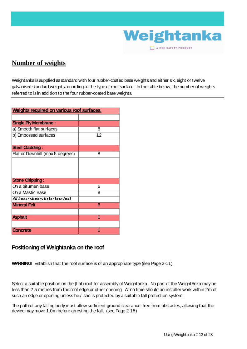
Number of weights
Weightanka is supplied as standard with four rubber-coated base weights and either six, eight or twelve galvanised standard weights according to the type of roof surface. In the table below, the number of weights referred to is in addition to the four rubber-coated base weights.
Weights required on various roof surfaces. Single Ply Membrane : a) Smooth flat surfaces 8 b) Embossed surfaces 12 Steel Cladding : Flat or Downhill (max 5 degrees) 8
Stone Chipping : On a bitumen base 6 On a Mastic Base 8 All loose stones to be brushed Mineral Felt 6 Asphalt 6 Concrete 6
Positioning of Weightanka on the roof
WARNING! Establish that the roof surface is of an appropriate type (see Page 2-11).
Select a suitable position on the (flat) roof for assembly of Weightanka. No part of the WeightAnka may be less than 2.5 metres from the roof edge or other opening. At no time should an installer work within 2m of such an edge or opening unless he / she is protected by a suitable fall protection system.
The path of any falling body must allow sufficient ground clearance, free from obstacles, allowing that the device may move 1.0m before arresting the fall. (see Page 2-15)
Using Weightanka 2-14 of 28
Establishing fall arrest clearance distance.
Where : A = Max length of line from Weightanka to harness attachment. B = Distance from line attachment on Weightanka to outer edge of parapet. C = Maximum potential movement of Weightanka (1m). D = A - B + C E = Maximum extension length of energy absorber (whether integral with the lanyard or not), consult relevant manufacturer. F = Stretch distance of harness and body of person (allow minimum 2m). G = Clearance allowance of 1m.
Using Weightanka 2-15 of 28
NB. Where a rope-adjuster is used, the distance D will be increased by any slack allowed in the rope and by any travel in the device during the fall. The manufacturer of any such device must be consulted for the determination of this additional allowance.
NB. Similarly, where a retractable type fall arrester is used, there may be some extension of the life line before the brake operates, thereby also increasing distance D. The manufacturer of any such device must be consulted for the determination of this additional allowance.
Manufacturers of these devices should also be consulted as to their suitability for horizontal
‘over-edge’ operation, as not all types are acceptable.
The clearance distance then = D + E + F + G = A + C + E + F + G - B
and since C = 1metre, F = 2metres & G = 1metre then :
Minimum clearance distance = A – B + E + 4 metres.*
“ * “ additional distance allowance may need to be made for some components see NB. above.
WARNING! If the roof surface is stone chippings, ensure that all loose chippings are removed from the area where the WeightAnka will sit, and the area across which it could travel in the event of a fall arrest incurring high forces. This may be achieved by sweeping the area with a hard broom. (See section 2.4 Page 9)
WARNING! Do not assemble Weightanka:
• where water accumulates. Otherwise, wet conditions are acceptable.
• where there is frost, ice or snow (or if these conditions are imminent);
• if the roof or the rubber-coated base weights are contaminated by oil, grease or other lubricant;
• if there is growth of algae on the rubber-coated base weights or in the area immediately adjacent to them;
• if there are loose chippings on the roof surface.
Using Weightanka 2-16 of 28
Dismantling the Weightanka system
When you wish to dismantle the Weightanka system reverse the sequence specified in the assembly instructions. Should the system need to be moved the base weights must be removed beforehand. Under no circumstances should the system be moved with the base weights attached
Using the Weightanka system
Contents How to use the system correctly.
Danger!
Do not use the Weightanka system if defects are identified during the checks described below or doubts exist over the integrity of the system. Defects can endanger life! Users of the system should be free from any disability that may affect them working at height in accordance with all relevant Health and Safety Regulations.
Always make the following checks before using the system!
Always carry out a check of the Weightanka system before use.
The check must include the following items:
• No part of the system is placed within 2.5 metres of a roof edge, open void or other fall hazard.
• Ensure that, in the case of a fall, your fall will be unobstructed. It is essential that you pay attention to the length of your personal protective equipment, including any energy absorber when fully extracted, and add one metre to allow for potential movement of the system itself. Always ensure there is adequate ground clearance at all times! Also ensure that in the case of a fall resulting in a pendulum swing, your swing will be unobstructed in all aspects.
• All base weights must be placed directly on the roof surface, evenly and without a gap between them and the supporting base. It is imperative that the rubber suction cups face downwards, and are in contact with the roof surface.
• Ensure that the correct number of weights have been used for the type of roof surface (see page 2-13) and that they are correctly distributed across the six securing pins (Fig.1 Page 2-4)
Using Weightanka 2-17 of 28
• Ensure that securing pins have been fitted to each Locating pin, thus preventing accidental removal of standard weights.
• Ensure that the roof is flat and that the slope is no more than 50
• Ensure that the means of connection (lanyard etc.) is not in contact with any sharp edges.
• Ensure the surface of the roof is free from oil, algae, ice, snow and standing water.
• Ensure the roof is structurally sound and shows no signs of damage
• Ensure the Weightanka system shows no sign of damage or defects.
• Ensure all screw threads are tightened firmly and the eyebolt torque using the tommy bar provided.
• Ensure the central attachment point of the Weightanka system is secure.
• A warning notice should be placed on the central eyebolt so that no one disconnects the personal protective equipment during use. This is the responsibility of the operator
• Ensure you have observed all the instructions for use of the personal protective equipment used in conjunction with the Weightanka system.
Exclusion zone
It is first necessary to establish an exclusion zone between WeightAnka and the roof edge, into which no one should be allowed unless connected to WeightAnka (or other appropriate anchor, if one exists). The exclusion zone should be designated by some form of marking or barrier, e.g. KEEMARK demarcation system.
Always make the following checks!
Always Ensure!
Each inspection must be recorded in an inspection book!
You will find a sample page at the end of these operating instructions.
Using Weightanka 2-18 of 28
Selection of suitable personal protective equipment
Advice!
The selection of suitable personal protective equipment (PPE) can only take place based on a risk assessment, which has been carried out in advance. The risk assessment and the selection of the PPE must be documented in writing!
Personal protective equipment (lanyard etc.) is not included with the Weightanka system. Personal protective equipment formed no part of the tests carried out by the
National Engineering Laboratory. Please ask your supplier for help in selecting the personal protective equipment suitable for you. The manufacturer of the chosen PPE must affirm that it can be used in the horizontal configuration and over the edge of any potential drop.
The personal protective equipment selected for protection against a fall must consist of the following parts:
A full body harness in accordance with EN 361 is the only acceptable body holding device. A safety belt in accordance with EN 358 is not suitable as a safety device!
A connector between the safety harness and the Weightanka system in accordance with EN 362.
Make sure that the personal protective equipment is suitable as a full fall arrest system. Consult the manufacturer if necessary.
During use ensure all PPE is protected from exposure to thermal electrical and mechanical shock or chemical attack
An emergency plan is in place for the recovery of any person who may fall.
Using Weightanka 2-19 of 28
Connecting personnel to the Weightanka system
Danger!
The Weightanka combination is intended for single person use for fall arrest purposes. In the case of use for restraint, it will accommodate two persons plus equipment, provided that the combination of the position of the Weightanka and the provision of a fixed length lanyard precludes either person from approaching within 0.5 metres of the roof edge.
Connecting to the Weightanka
All personal protection equipment must be connected exclusively with the connector elements approved for the purpose to the eyebolt on the central pedestal (see figs. 1 and 2). No other form of fastening, e.g. to the cross arms, stabilisers (or to the tapped holes in the cross arms) or by knots is permitted as life may be endangered.
Final Checks After you have connected, ensure:
• all connector elements of the personal safety equipment (e.g. Karabiner hooks) are correctly closed and locked,
• the connecting elements of the personal protective equipment move freely in the eye of the central attachment point,
• no load will be applied across the safety catches of any karabiners or other connectors.
Maintenance, Inspection and Disposal
Contents Information on the care and regular inspection of the Weightanka system, to be carried out by a competent person who is familiar with the product.
Re-Selling Should the Weightanka system be re-sold or exported outside of the original country of destination, the re-seller shall provide the user with these instructions in the language of the country in which the product is to be used.
Using Weightanka 2-20 of 28
Cleaning In most cases cleaning with clean water is adequate. You can use a water hose or high-pressure cleaner for this purpose. If you are unsure of the nature of any contamination contact the manufacturer for advice. After cleaning or when the system has become wet through use, the system must be allowed to air dry naturally and be kept away from direct heat before next use.
Maintenance The Weightanka system is virtually maintenance-free. However, any damaged or corroded components and damaged bolts must be exchanged for original spare parts before using again.
Regular Obligatory Inspection of Weightanka
General
WARNING! The safety of users depends upon the continued efficiency and durability of their equipment. It is recognised that checks, inspections and examinations are a contributory factor in reducing risks. It is essential, therefore, that these inspections and examinations are carried out as recommended, and as required by National regulations.
Pre-use checks, inspections and examinations should only be carried out by persons competent to do so. A competent person is defined as a designated person who is knowledgeable of the current checking, inspection and examination requirements, recommendations and instructions issued by the manufacturer applicable to the relevant component, subsystem or system. This person should be capable of identifying defects, should be responsible for initiating the corrective action to be taken and should have the necessary skills and resources to do so.
Once in place at the worksite, the Weightanka combination should be checked before each use (Pre-use check – see below) to ensure that the whole system functions correctly.
After every week of constant use, every six weeks of intermittent use and on each occasion of re-assembly, before they are used again, Weightanka should be more closely inspected, e.g. for signs of damage, to ensure that it is safe for re-use. This inspection (i.e. interim inspection ) should be recorded.
At least every 12 months there should be a thorough examination (i.e. a detailed inspection, more thorough than the interim inspection) This thorough examination should be recorded on the Inspection sheet attached.
Using Weightanka 2-21 of 28
Pre-use checks.
Before each use of this equipment, including after initial assembly, carry out a pre-use check to ensure that it is in an acceptable condition and that it operates correctly. This check should include at least the points below:
Make a final inspection of the assembled Weightanka. Ensure that all the instructions for their assembly and location have been followed. Special attention should be paid to the following:
(a) that no part of WeightAnka is positioned less than 2.5m from the roof edge or other opening and that no change has occurred to the available clear fall distance.
(b) that the patterned surfaces of the rubber-coated base weights are on the underside, in contact with the roof surface;
(c) that the correct number of weights have been used in the correct configuration, i.e. their position on the locating pins.
(d) that the roof surface is of an appropriate type and angle and that the surface conditions are satisfactory.
(e) that the securing pins have been fitted to each locating pin to ensure that the weights are captive;
(f) that the eyebolt/pedestal assembly has been tightened in accordance with the instructions;
(g) that a PPE warning disc has been fitted between the eyebolt and the pedestal.
(h) that two instruction labels are attached to the upper cross arm of Weightanka, and that they are legible. Replacements are available from your Weightanka supplier.
(i) that there is no damage or defect to the Weightanka;
(j) that any recommendations for use with other components in the system, as advised on the record card, are complied with;
(k) that there is no damage to the roof surface upon which the Weightanka stands;
(l) that neither the roof surface nor the Weightanka have been contaminated by oil, grease or any other substance;
(m) that there is no growth of algae on the rubber base weights or on the surrounding roof surface. If algae are present on, or immediately adjacent to, the rubber base weights, the assembly should be dismantled, scrupulously cleaned, and re-assembled in accordance with this document;
(n) that any loose chippings have been removed where necessary.
WARNING! The lanyard MUST ONLY be attached to the eyebolt provided on the Weightanka pedestal. See Figure . It would be dangerous to attach the lanyard to any other part of the Weightanka.
The assembly of the Weightanka is now complete.
Using Weightanka 2-22 of 28
WARNING! Should any doubt arise about the safety of any part of the system, do not use it and remove it from service immediately.
Instructions for periodic examination
General
In the UK, the Weightanka is subject to the Personal Protective Equipment at Work Regulations 1992 and amendments and employers should be knowledgeable of this.
What to look for during, inspections and thorough examination
The lists below are not exclusive.
Inspection (Interim inspection)
An inspection should be carried out after every week of constant use, every six weeks of intermittent use and on each occasion of re-assembly, and recorded. In addition to the pre-use checks. Inspect for the following:
(a) For signs of corrosion, wear, distortion or other defects on all parts including bolts and nuts;
(b) That the rubber on the base weights is fully bonded to the steel and that there is no damage to the suction cups. Any algae should be removed from the rubber base;
(c) That the two warning notices are still intact and legible on the top cross arm. (Replacements notices are available from your Weightanka supplier.)
(d) Unless stored out of use, re-assemble in accordance with section 2.5 of this document.
(e) Should any doubt arise about the safety of any part of the system, do not use it, remove it from service immediately, and seek advice from your WeightAnka supplier.
Thorough Examination (Detailed inspection)
A thorough examination should be carried out and recorded on the Inspection Record by a competent person, authorised by the manufacturers approved agent, at least every 12 months.
Ensure that Weightanka is completely dismantled and inspect as follows:
All checks as per interim inspection.
In addition;
a) That there is no wear or distortion of the holes through which the various bolts and pins are passed,
b) That there is no deformation of any of the pins or bolts, or of their threads.
Using Weightanka 2-23 of 28
c) That there is no other evidence to suggest the Weightanka has arrested a fall. This might be; scrape marks across the roof, or deformation of the pedestal, cross arms, stabiliser, eyebolt etc. This list is not exclusive.
Should any doubt arise about the safety of any part of the system, do not use it , remove it from service immediately and seek advice from your Weightanka supplier.
Instructions for repair; following a fall or any other possibly damaging event. If an operative suffers a fall from a height while using the Weightanka, or if it becomes damaged in any way, the manufacturer should be contacted and arrangements made to return it to them for inspection and any necessary repair. WARNING! Do not attempt to repair Weightanka unless written permission has been obtained from the manufacturer or authorised representative. Records It is strongly recommended that a record be kept for each WeightAnka. The record should contain headings for and spaces to allow entry of at least the details shown in the appendix:
Using Weightanka 2-24 of 28
Markings on the products and their meaning
Various markings can be found on WeightAnka, these are located on the top cross arm and on the galvanised weights. These markings are as follows, any queries about their interpretation should be addressed to the manufacturer.
LABEL 1 CE0194
“CE0194” confirms that Weightanka has been CE approved to the PPE directive and that it is subject to ongoing monitoring under arrangements monitored by notified body No 0194 (Inspec International)
LABEL 2.
WEIGHTANKA MAY ONLY BE USED ON THE FOLLOWING SURFACES. THE ASSEMBLY MUST ALWAYS COMPRISE FOUR RUBBER COVERED BASE WEIGHTS, PLUS ADDITIONAL GALVANISED WEIGHTS DEPENDING ON THE TYPE OF ROOF SURFACE AS FOLLOWS:
1) SINGLE PLY MEMBRANE
a) SMOOTH FLAT SURFACES – 8 GALVANISED WEIGHTS b) EMBOSSED SURFACES -- 12 GALVANISED WEIGHTS
WEIGHTANKA is a deadweight anchor device to EN795:1997 – class ‘E’
‘WEIGHTANKA’ should never be used during periods when there is frost, ice or snow on the roof.
‘WEIGHTANKA’ should not be used to support horizontal lines or for abseiling – special products ‘WIREANKA’ and ‘ACCESSANKA’ are available for these applications.
All Users Must Be Fully Conversant With The Instructions For Use Supplied With This Anchor Device.
Number Of Users
A) For Fall Arrest Purposes – Max one user at any one time B) For Restraint – Providing that the combination of the position of the weightanka and the use of
fixed length harnesses ensure that the users are not able to approach within 0.5m of a roof edge or other opening – Max Two Users.
All Users Should Be Protected By An Energy Absorber To EN355.
‘WEIGHTANKA’ should be positioned with no part of the assembly less than 2500mm from any roof edge or roof opening. There must always be sufficient clearance to arrest a falling person, see Instructions For Use. The path of a falling person must be free from obstacles (e.g. Canopies).
EN 795:1997 Class E Manufacturers Serial No. 2086
Disposal
The Weightanka system consists predominantly of ferrous metals protected with zinc rich coatings - with the exception of the rubber coated base weights.
l The system can, therefore, be disposed of in a scrap-metal facility
Amendments Page 1 of 1
ISSUE
No. AMMENDMENTS MADE DATE
MODIFIED
1 First Issue 1st Jul 2008
2 Front Cover changed – Class E instead of Class B 30th Sept 2008
3 Page 13 – Chapter 2 – Removal of uphill version on steel cladding. Page 28 – Chapter 2 – As above for label 2


![[XLS] · Web view58535453-2.921390165 0.13 4 0 195972866-2.8262329319999999 0.14000000000000001 1 0 82617546-1.846843212 0.28000000000000003 0 0 0 262231746-1.727379545 0.3 8 3 0](https://static.documents.pub/doc/80x56/5b075a377f8b9a58148e2bdb/xls-view58535453-2921390165-013-4-0-195972866-28262329319999999-014000000000000001.jpg)


