WA200-5 WA 250 HORSEPOWER Gross: 95 kW 127 HP @ 2000 rpm Net: 92 kW 123 HP @ 2000 rpm OPERATING WEIGHT 9425 – 9555 kg 20,779 – 21,065 lb BUCKET CAPACITY 1.7 –2.4 m 3 2.2 – 3.1 yd 3 Photo may include optional equipment. WA 200 WHEEL LOADER
Transcript
WA200-5
WA
250
HORSEPOWERGross: 95 kW 127 HP @ 2000 rpm
Net: 92 kW 123 HP @ 2000 rpm
OPERATING WEIGHT9425 – 9555 kg
20,779 – 21,065 lb
BUCKET CAPACITY1.7 –2.4 m3 2.2 –3.1 yd3
Photo may include optional equipment.
WA
200
WH
EE
L L
OA
DE
R
Larger cab with new layout design
Extended service intervals
Powerful and low emission Komatsu SAA6D102E-2 engine
Full side opening gull-wing engine doors
Expanded main monitor and troubleshooting display
Reduced operator noise to 70 dB(A)
New tilt steering column
Ground level servicingand fluid checks
Staircase-type stepswith large rear-hinged doors
Side-by-side type coolersfor easy access and cleaning
Extremely low fuel consumption
Easy-to-operate loader control mono-lever using PPC (Proportional Pressure Control)
Large breakout force
Maintenance-free fully hydraulicwet-disc service and parking brakes
Electronically controlled Hydrostatic Transmission(HST) with variable shift control system
Traction control system
Radial Sealedair cleaner
Overrun protection system
Swing-out hydraulicradiator fan
Flat face "O-Ring" Hydraulic Sealsfor extended life
Sealed DT electrical connectors
W H E E L L O A D E R
WALK-AROUNDWHEEL LOADER
HORSEPOWERGross: 95 kW 127 HP @ 2000 rpmNet: 92 kW 123 HP @ 2000 rpm
OPERATING WEIGHT9425 – 9555 kg
20,779 – 21,065 lb
BUCKET CAPACITY1.7 – 2.4 m3
2.2 – 3.1 yd3
WA200-5WA200-5
32
Komatsu-integrateddesign offers the bestvalue, reliability, and versatility.Hydraulics, powertrain, frame,and all other major componentsare engineered by Komatsu.You get a machine whosecomponents are designed to work together for higherproduction, greater reliability,and more versatility.
Photos may include optional equipment.
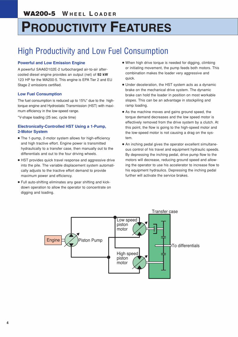
Powerful and Low Emission Engine
A powerful SAA6D102E-2 turbocharged air-to-air after-cooled diesel engine provides an output (net) of 92 kW123 HP for the WA200-5. This engine is EPA Tier 2 and EUStage 2 emissions certified.
Low Fuel Consumption
The fuel consumption is reduced up to 15%* due to the high-torque engine and Hydrostatic Transmission (HST) with maxi-mum efficiency in the low-speed range.
*V-shape loading (25 sec. cycle time)
Electronically-Controlled HST Using a 1-Pump,2-Motor System
● The 1-pump, 2-motor system allows for high-efficiencyand high tractive effort. Engine power is transmittedhydraulically to a transfer case, then manually out to thedifferentials and out to the four driving wheels.
● HST provides quick travel response and aggressive driveinto the pile. The variable displacement system automati-cally adjusts to the tractive effort demand to providemaximum power and efficiency.
● Full auto-shifting eliminates any gear shifting and kick-down operation to allow the operator to concentrate ondigging and loading.
● When high drive torque is needed for digging, climbingor initiating movement, the pump feeds both motors. Thiscombination makes the loader very aggressive andquick.
● Under deceleration, the HST system acts as a dynamicbrake on the mechanical drive system. The dynamicbrake can hold the loader in position on most workableslopes. This can be an advantage in stockpiling andramp loading.
● As the machine moves and gains ground speed, thetorque demand decreases and the low speed motor iseffectively removed from the drive system by a clutch. Atthis point, the flow is going to the high-speed motor andthe low-speed motor is not causing a drag on the sys-tem.
● An inching pedal gives the operator excellent simultane-ous control of his travel and equipment hydraulic speeds.By depressing the inching pedal, drive pump flow to themotors will decrease, reducing ground speed and allow-ing the operator to use his accelerator to increase flow tohis equipment hydraulics. Depressing the inching pedalfurther will activate the service brakes.
High Productivity and Low Fuel Consumption
Piston PumpEngine
Low speedpistonmotor
High speedpistonmotor
Transfer case
To differentials
Electronically-Controlled HST with Variable ShiftControl System
The operator can choose between first, second, third or
fourth maximum speeds by dialing the speed range selector
switch.
For v-cycles, the operator can set the speed control switch to
1 or 2, which will
give him aggres-
sive digging, quick
response and fast
hydraulics. For
load and carry, he
can select 3 or 4
which will still give
aggressive digging
but with much
faster travel
speed.
The variable shift
switch allows the
operator to adjust his machine speed in confined v-loading
applications. When in 1, the operator can adjust his travel
speed using the variable shift switch to match his machine
speed and hydraulics to the distance he must travel.
Traction Control System
In limited traction situations where the operator would like
to avoid tire slippage (such as sandy or wet surface opera-
tions), he can automatically reduce slippage by activating
the traction control feature. Putting the traction control
switch in the “ON” position limits the maximum amount of
tractive effort.
Traction control will
be an advantage in
certain appplica-
tions such as trans-
fer stations where
the loader may be
working on slippery
concrete.
4 8 12 16 20
Variable rangeof travel speed
Travel speed
Tra
ctiv
e ef
fort
km/h
MPH0 8 10 12642
0 4 8 12 16 20
Tra
ctiv
e ef
fort
Travel speed
Reduced
km/h
MPH0 8 10 12642
0
Traction ControlVariable Shift Control
PRODUCTIVITY FEATURESWHEEL LOADER WA200-5
54
W H E E L L O A D E RWA200-5
Fully Hydraulic Wet Multi-disc Service Brakes
The dual wet disc brakes at each wheel are fully sealed and
adjustment free to reduce contamination, wear and mainte-
nance. The result is lower maintenance costs and higher reli-
ability.
Added dependability is designed into the braking system by
the use of two independent hydraulic circuits, providing
hydraulic backup should one of the circuits fail.
If the brake oil pressure drops, the warning lamp flashes and
the warning buzzer sounds intermittently.
The parking brake is mechanically controlled by a lever in the
cab.
High-rigidity Frames
The front and rear frames along with the loader linkage have
high rigidity to withstand repeated twisting and bending loads
to the loader body and linkage. Both the upper and lower
center pivot bearings use tapered roller bearings for
increased durability.The structure is similar to those of large
sized loaders and the reinforced loader linkage ensures high
strength.
Flat Face-to-Face O-Ring Seals
Flat face-to-face
O-ring seals are
used to securely
seal all hydraulic
hose connections
and to prevent oil
leakage.
Cathion Electrodeposition Primer Paint/PowderCoating Final Paint
Cathion electrodeposition paint is applied as a primer paint
and powder coating is applied as a topcoat to the exterior
metal sheet parts. This process results in a durable rust-free
machine, even in the most severe environments. Some
external parts are made of plastic to provide long life and
high impact resistance.
Sealed DT Connectors
Main harnesses and controller connectors are equipped with
sealed DT connectors providing high reliability and dust and
corrosion resistance.
Komatsu Components
Komatsu manufactures
the engine, transfer
case, differentials and
electric parts on this
wheel loader. Komatsu
loaders are manufac-
tured with an integrated
production system under
a strict quality control
system.
Main Monitor - EMMS (Equipment ManagementMonitoring System)
Komatsu’s new main monitor keeps the operator informed of
all machine functions at a glance. The monitor is located
behind the steering wheel and displays various different
machine functions including fluid/filter change intervals and
troubleshooting memory display functions. The main gauges
are analog type for easy viewing and other functions utilize
light symbols or LCD readouts.
Swing-Out Radiator
The new Komatsu
cooling system is
isolated from the
engine to provide
more efficient cool-
ing and low noise.
The swing-out
hydraulic fan allows
the operator to
quickly clean out
the cooling system.
The radiator, air-to-air cooler and oil cooler are mounted
side-by-side for more efficient cooling and easy cleaning. A
fully-opening, gas spring assisted rear grill gives the operator
excellent access to the swing-out fan and coolers.
Full Side-Opening Gull-Wing Engine Doors
Ground level engine service and daily service checks are
made easy with the gas spring assisted full side opening
gull-wing doors.
Extended Service Interval
Extended engine oil change interval:
250 H 500 H
Extended drive shaft greasing interval:1,000 H 4,000 H
Overrun Prevention System
When the machine descends a slope of six degrees or less,
maximum travel speed is automatically restricted to approxi-
mately 38 km/h 24 MPH, for safety protection against dam-
age of power train components and brakes by sensing the
travel speed and controlling the discharge amount of the
HST pump and motor. When the machine descends a steep
slope and the travel speed reaches 36 km/h 22 MPH, the
caution lamp lights up to inform the operator to reduce the
travel speed.
Note: When the machine descends a steep slope, the use
of the service brake is necessary to limit travel speed.
nipple
hose O-ring
Front axle Rear axleTransfer
Engine
Komatsu Components
Parking Brake Service Brakes
INCREASED RELIABILITY AND SERVICEABILITYWHEEL LOADER WA200-5
76
W H E E L L O A D E RWA200-5
New Cab Layout
Komatsu’s new cab layout provides the operator with a
roomy, quiet and efficient work environment. The low noise
level inside the cab leads the industry at 70 dB(A) and loader
controls are ergonomically designed to reduce operator
fatigue and increase productivity.
Two Door Walk-Through Cab
Entry and exit into the new
Komatsu cab starts with
sloped staircase type
steps and large diameter
handrails for added safety
and comfort. The large cab
doors are rear-hinged to
open 130 degrees offering
easy entry/exit and will not
hamper visibility when
operating the machine with
the doors latched open. A
wide pillar-less flat glass provides for excellent visibility. The
wiper arm covers a large area to provide great visibility even
on rainy days.
Low-noise Design
Operator noise: 70 dB(A)
The large cab is
mounted with
Komatsu’s unique
ROPS/FOPS vis-
cous mounts. The
low-noise engine,
hydraulically driven
fan, and hydraulic
pumps are mounted
with rubber cush-
ions, and the cab sealing is improved to provide a quiet,
low-vibration, and comfortable operating environment.
Pressurization in the cab keeps dirt out further enhancing
the operator’s comfort.
Easy-to-operate Loader Control Mono-lever
A new mono-lever using PPC (Proportional Pressure Control)
allows the operator to easily operate the work equipment, to
reduce operator fatigue and to increase controllability. The
adjustable wrist rest provides the operator with a variety of
comfortable operating positions.
Electrically Controlled Directional Lever
The operator can change direction with a touch of his fingers
without removing his hand from the steering wheel. Solid
state electronics makes this possible.
Tiltable Steering Column
The operator can tilt the
steering column to allow max-
imum comfort and control.
The two-spoke steering
wheel allows maximum visi-
bility of the monitor panel and
forward work environment.
Comforts of Home
The large cab allows
room for a large lunch
box holder, a variety of
cup holders and a
hot/cold box storage
area. Optional air condi-
tioning and the optional
AM/FM stereo cassette
system create a com-
fortable and controlled
work environment.
OPERATOR COMFORTWHEEL LOADER WA200-5
98
W H E E L L O A D E RWA200-5
17.5-25 tires 20.5-25 tiresTread 1930 mm 6'4" 1930 mm 6'4"Width over tires 2375 mm 7'10" 2470 mm 8'1"
A Wheelbase 2840 mm 9'4" 2840 mm 9'4"B Hinge pin height at max. height 3635 mm 11'11" 3705 mm 12'2"C Hinge pin height at carry position 410 mm 1'4" 380 mm 1'3"D Ground clearance 425 mm 1'5" 495 mm 1'8"E Hitch height 870 mm 2'10" 940 mm 3'1"F Overall height, top of stack 2715 mm 8'11" 2785 mm 9'2"G Overall height, ROPS cab 3110 mm 10'2" 3180 mm 10'5"H See Dumping Clearance Below
Change in Change in Tipping Load Width Ground Change in Change inOperating Weight Straight Full Turn Over Tire Clearance Vertical Dimensions Reach
17.5-25-12PR (L3) 105 kg 231 lb 80 kg 176 lb 70 kg 154 lb 2375 mm 7'10" 425 mm 1'5" 0 mm 0" 0 mm 0"
20.5-25-12PR (L2) 450 kg 992 lb 240 kg 529 lb 220 kg 485 lb 2470 mm 8'1" 495 mm 1'8" 70 mm 2.8" –75 mm –3.0"
20.5-25-12PR (L3) 665 kg 1,466 lb 355 kg 783 lb 320 kg 705 lb 2470 mm 8'1" 495 mm 1'8" 70 mm 2.8" –75 mm –3.0"
Install ROPS canopy (instead of cab) –250 kg –551 lb –250 kg –551 lb –220 kg –485 lb
Additional counterweight 300 kg 661 lb 590 kg 1,301 lb 510 kg 1,124 lb
Air conditioner 70 kg 154 lb 60 kg 132 lb 50 kg 110 lb
BUCKET CONTROLS
The use of a PPC hydraulic control valve offers lighter operating effortfor the work equipment control levers. The reduction in the lever effortand travel makes it easy to operate in the work environment.
Bucket Width 2550 mm 8'4" 2550 mm 8'4" 2550 mm 8'4"
Bucket Weight 785 kg 1,731 lb 740 kg 1,631 lb 875 kg 1,929 lb
Static Tipping LoadStraight 8400 kg 18,519 lb 8460 kg 18,652 lb 8250 kg 18,188 lb
40° full turn 7300 kg 16,094 lb 7360 kg 16,226 lb 7175 kg 15,818 lb
Dumping Clearance,maximum height and 45° dump angle (H)** 2760 mm 9'1" 2815 mm 9'3" 2655 mm 8'9"
Reach at 2130 mm 7'45° dump angle** 1480 mm 4'10" 1455 mm 4'9" 1530 mm 5'0"
Reach at maximum heightand 45° dump angle** 1000 mm 3'3" 945 mm 3'1" 1105 mm 3'8"
Reach with arm horizontaland bucket level** 2215 mm 7'3" 2135 mm 7'0" 2365 mm 7'9"
Operating Height Fully raised 4885 mm 16'0" 4765 mm 15'8" 4995 mm 16'5"
Overall Length Bucket on Ground 6895 mm 22'7" 6820 mm 22'5" 7050 mm 23'2"
Turning Radius* 5650 mm 18'6" 5620 mm 18'5" 5715 mm 18'9"
Digging Depth0° 135 mm 5.3" 135 mm 5.3" 135 mm 5.3"
10° 320 mm 1'1" 305 mm 1'0" 345 mm 1'2"
Breakout Force 9500 kg 20,944 lb 10450 kg 23,038 lb 8300 kg 18,298 lb
Operating Weight 9470 kg 20,878 lb 9425 kg 20,779 lb 9555 kg 21,065 lb
DIMENSIONS
�
�
�
�
�
��
�
* Bucket at carry, outside corner of bucket. **At the end of B.O.C.
All dimensions, weights, and performance values based on SAE J732c and J742b standards. Static tipping load and operating weight shown include lubricant,coolant, full fuel tank, ROPS cab and operator. Machine stability and operating weight affected by counterweight, tire size, and other attachments.
17.5-25 tires 20.5-25 tires1st* 4.0 - 13.0 km/h 2.5 - 8.1 mph 4.4 - 14.3 km/h 2.7 - 8.9 mph2nd 13.0 km/h 8.1 mph 14.3 km/h 8.9 mph3rd 20.0 km/h 12.4 mph 22.0 km/h 13.7 mph4th 34.5 km/h 21.4 mph 38.0 km/h 23.6 mph
Hydraulic Number ofCylinders Cylinders Bore Stroke
Boom 2 120 mm 4.7" 673.5 mm 26.5"Bucket 1 130 mm 5.1" 493 mm 19.4"
Steering 2 70 mm 2.8" 453 mm 17.8"
1686
2.2
2.6
3.1
2023 2360 2698 3035 3372 3709
Light Material Bucket(Scooping and loading of light material)
Stockpile Bucket(Loading and excavating of soil, sand and avariety of other commonly handled material)
Excavating Bucket(Loading and excavating of crushed or blasted rock)
115 100 95%
Bucket fill factor
yd3
Buck
et c
apac
ity:
m3
yd3 m3
2.4
2.0
1.7
Material density: kg/m3 lb/yd3
1000 1200 1400 1600 1800 2000 2200
SPECIFICATIONSWHEEL LOADER WA200-5
1110
W H E E L L O A D E RWA200-5
17.5-25 tires 20.5-25 tiresTread 1930 mm 6'4" 1930 mm 6'4"Width over tires 2375 mm 7'10" 2470 mm 8'1"
A Wheelbase 2840 mm 9'4" 2840 mm 9'4"B Hinge pin height at max. height 3635 mm 11'11" 3705 mm 12'2"C Hinge pin height at carry position 410 mm 1'4" 380 mm 1'3"D Ground clearance 425 mm 1'5" 495 mm 1'8"E Hitch height 870 mm 2'10" 940 mm 3'1"F Overall height, top of stack 2715 mm 8'11" 2785 mm 9'2"G Overall height, ROPS cab 3110 mm 10'2" 3180 mm 10'5"H See Dumping Clearance Below
Change in Change in Tipping Load Width Ground Change in Change inOperating Weight Straight Full Turn Over Tire Clearance Vertical Dimensions Reach
17.5-25-12PR (L3) 105 kg 231 lb 80 kg 176 lb 70 kg 154 lb 2375 mm 7'10" 425 mm 1'5" 0 mm 0" 0 mm 0"
20.5-25-12PR (L2) 450 kg 992 lb 240 kg 529 lb 220 kg 485 lb 2470 mm 8'1" 495 mm 1'8" 70 mm 2.8" –75 mm –3.0"
20.5-25-12PR (L3) 665 kg 1,466 lb 355 kg 783 lb 320 kg 705 lb 2470 mm 8'1" 495 mm 1'8" 70 mm 2.8" –75 mm –3.0"
Install ROPS canopy (instead of cab) –250 kg –551 lb –250 kg –551 lb –220 kg –485 lb
Additional counterweight 300 kg 661 lb 590 kg 1,301 lb 510 kg 1,124 lb
Air conditioner 70 kg 154 lb 60 kg 132 lb 50 kg 110 lb
BUCKET CONTROLS
The use of a PPC hydraulic control valve offers lighter operating effortfor the work equipment control levers. The reduction in the lever effortand travel makes it easy to operate in the work environment.
Bucket Width 2550 mm 8'4" 2550 mm 8'4" 2550 mm 8'4"
Bucket Weight 785 kg 1,731 lb 740 kg 1,631 lb 875 kg 1,929 lb
Static Tipping LoadStraight 8400 kg 18,519 lb 8460 kg 18,652 lb 8250 kg 18,188 lb
40° full turn 7300 kg 16,094 lb 7360 kg 16,226 lb 7175 kg 15,818 lb
Dumping Clearance,maximum height and 45° dump angle (H)** 2760 mm 9'1" 2815 mm 9'3" 2655 mm 8'9"
Reach at 2130 mm 7'45° dump angle** 1480 mm 4'10" 1455 mm 4'9" 1530 mm 5'0"
Reach at maximum heightand 45° dump angle** 1000 mm 3'3" 945 mm 3'1" 1105 mm 3'8"
Reach with arm horizontaland bucket level** 2215 mm 7'3" 2135 mm 7'0" 2365 mm 7'9"
Operating Height Fully raised 4885 mm 16'0" 4765 mm 15'8" 4995 mm 16'5"
Overall Length Bucket on Ground 6895 mm 22'7" 6820 mm 22'5" 7050 mm 23'2"
Turning Radius* 5650 mm 18'6" 5620 mm 18'5" 5715 mm 18'9"
Digging Depth0° 135 mm 5.3" 135 mm 5.3" 135 mm 5.3"
10° 320 mm 1'1" 305 mm 1'0" 345 mm 1'2"
Breakout Force 9500 kg 20,944 lb 10450 kg 23,038 lb 8300 kg 18,298 lb
Operating Weight 9470 kg 20,878 lb 9425 kg 20,779 lb 9555 kg 21,065 lb
DIMENSIONS
�
�
�
�
�
��
�
* Bucket at carry, outside corner of bucket. **At the end of B.O.C.
All dimensions, weights, and performance values based on SAE J732c and J742b standards. Static tipping load and operating weight shown include lubricant,coolant, full fuel tank, ROPS cab and operator. Machine stability and operating weight affected by counterweight, tire size, and other attachments.
lighter/ash tray, dome light, floor mat,front (intermittent) and rear wiper/washer,rear view mirrors (2 outside, 1 inside),right hand and left hand door access withsteps, sun visor