+ All Categories
Home > Documents > WAFER BUTTERFLY VALVE PN10/16 - armat.cz · 6 O ring NBR 7 Circlip Steel 8 Circlip Steel Lever...

WAFER BUTTERFLY VALVE PN10/16 - armat.cz · 6 O ring NBR 7 Circlip Steel 8 Circlip Steel Lever...

Date post: 25-Jan-2019
Category:
Upload: vodieu
View: 224 times
Download: 0 times
Share this document with a friend
10
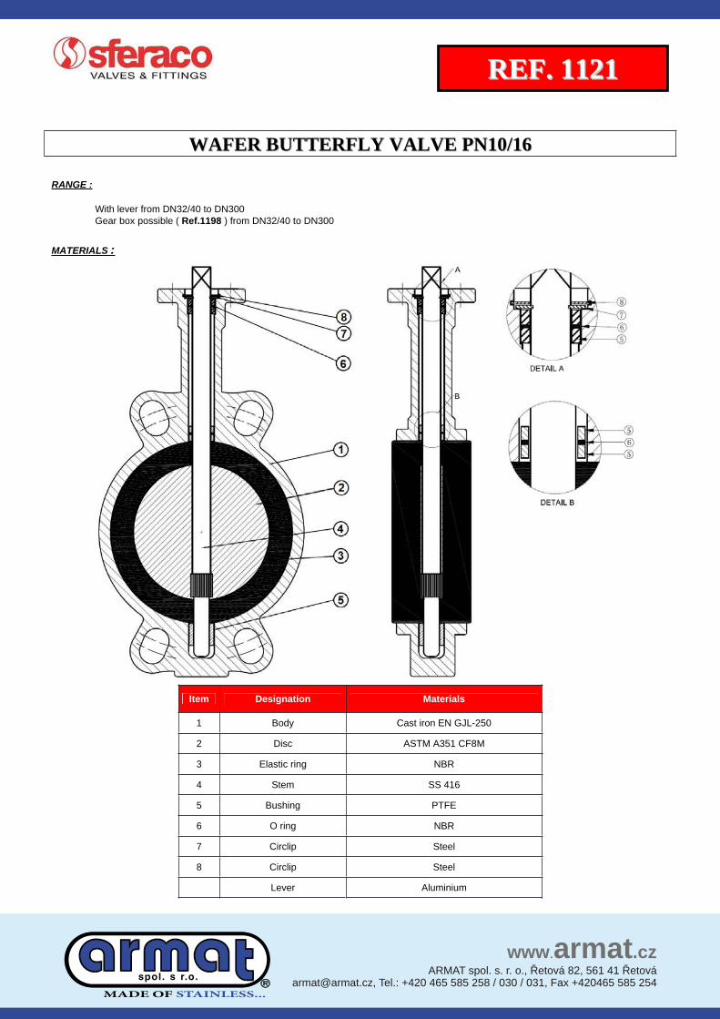
WAFER BUTTERFLY VALVE PN10/16 R R E E F F . . 1 1 1 1 2 2 1 1 Size : Ends : Min Temperature : Max Temperature : DN 32/40 to DN 300 Between flanges PN10/16 and Class 150 (PN20) -10°C + 80°C Max Pressure : 16 Bars Specifications : Long neck for isolation Stainless steel disc NBR vulcanized seat Materials : Cast iron body MADE OF STAINLESS... MADE OF STAINLESS ...
Transcript

WWAAFFEERR BBUUTTTTEERRFFLLYY VVAALLVVEE PPNN1100//1166

RREEFF.. 11112211

Size : Ends :

Min Temperature : Max Temperature :

DN 32/40 to DN 300 Between flanges PN10/16 and Class 150 (PN20) -10°C+ 80°C

Max Pressure : 16 BarsSpecifications : Long neck for isolation

Stainless steel disc NBR vulcanized seat

Materials : Cast iron body

MADE OF STAINLESS...

MADE OF STAINLESS ...

WWAAFFEERR BBUUTTTTEERRFFLLYY VVAALLVVEE PPNN1100//1166

RREEFF.. 11112211

SPECIFICATIONS :

Long neck for isolation ISO 5211 mounting pad Wafer type Between flanges PN10/16 from DN32 to DN300 and Class 150 (PN20) from DN40 to DN300 Full crossing stem With 10 positions lever and locking device up to DN150 Double PTFE gasket on stem Stainless steel disc Epoxy painting RAL003 80 microns thickness Vulcanized NBR elastic ring

USE :

No aromatic hydrocarbon, fuel, water, natural gas, grease, oil, compressed air, glycol Min and max Temperature Ts : - 10°C to + 80°C Max Pressure Ps : 16 bars

FLOW COEFFICIENT Kv ( M3 / h ) :

DN 32/40 50 65 80 100 125 150 200 250 300

Ope

ning

ang

le

10° 0,04 0,05 0,09 0,17 0,26 0,43 0,68 1,7 2,6 3,4

20° 2 3 5 8 15 25 38 76 129 200

30° 5 6 10 15 31 52 81 160 273 422

40° 10 13 21 33 67 113 175 348 592 914

50° 18 23 38 60 119 202 312 620 1055 1630

60° 30 38 64 99 196 334 516 1025 1746 2697

70° 48 60 102 156 310 529 817 1623 2764 4269

80° 72 90 152 235 466 793 1226 2434 4145 6403

90° 78 98 167 258 512 872 1347 2675 4555 7037

TORQUE VALUE ( Nm, without safety coefficient ) :

We recommend a safety coefficient of 30% minimum to determinate the actuator.

DN 32/40 50 65 80 100 125 150 200 250 300

PN10 11 15 24 31 48 73 106 177 281 410

PN16 12 16 26 33 53 81 119 194 308 441

MADE OF STAINLESS...

WWAAFFEERR BBUUTTTTEERRFFLLYY VVAALLVVEE PPNN1100//1166

RREEFF.. 11112211

RANGE :

With lever from DN32/40 to DN300 Gear box possible ( Ref.1198 ) from DN32/40 to DN300

MATERIALS :

Item Designation Materials

052-LJG NE nori tsaC ydoB 1

M8FC 153A MTSA csiD 2

RBN gnir citsalE 3

614 SS metS 4

EFTP gnihsuB 5

RBN gnir O 6

leetS pilcriC 7

leetS pilcriC 8

muinimulA reveL

MADE OF STAINLESS...

WWAAFFEERR BBUUTTTTEERRFFLLYY VVAALLVVEE PPNN1100//1166

RREEFF.. 11112211

MATERIALS GEARBOX :

Item Designation Materials leets demorhC metS 1

613 SS niP 2

3 Indicator plate Aluminium + NBR gasket

4 Indicator bolt, washer SS 316

613 SS rehsaw ,tloB 5

leetS 1 raeG 6

7 Gear 2 Ductile iron EN GJS-400-15

RBN gnir O 8

RBN teksag tennoB 9

10 Internal set screw Carbon steel

613 SS wercs tes lanretxE 11

citsalP pac citsalP 21

13 Handwheel Cast iron EN GJL-250 epoxy coating

14 Bonnet Cast iron EN GJL-250 epoxy coating

15 Body Cast iron EN GJL-250 epoxy coating

403 SS evlav no xif ot gnitloB

MADE OF STAINLESS...

WWAAFFEERR BBUUTTTTEERRFFLLYY VVAALLVVEE PPNN1100//1166

RREEFF.. 11112211

VALVES SIZE ( in mm ) :

VALVES WITH LEVER DN 32/40 - 300 :

Ref. DN 32/40 50 65 80 100 125 150 200 250 300

1121

A 61 77 87,5 95 107 121,5 144 171 205 235

B 130 136,5 142 158 180 192 215 242 280 310

Ø De 82 95 109 121 152 180 207 260 315 370

E 33 43 46 46 52 56 56 60 68 78

H 70 70 70 70 70 71 71 40 44 44

L 195 195 195 195 195 278 278 355 507 507

Ø P 65 65 65 65 65 90 90 125 150 150

Weig. (Kg) 1.85 2.53 2.86 3.16 4.21 6.67 7.66 14.67 23.4 33.8

MADE OF STAINLESS...

WWAAFFEERR BBUUTTTTEERRFFLLYY VVAALLVVEE PPNN1100//1166

RREEFF.. 11112211

GEAR BOX SIZE ( in mm ) :

DN 32/80 100 125/150 200 250 300

C 9 11 14 17 22 27

Ø K 50 50 70 102 125 125

ISO F05 F05 F07 F10 F12 F12

Nx ØZ 4 x M6 4 x M6 4 x M8 4 x M10 4 x M12 4 x M12

L1 156 156 156 241 223 223

Ø V 150 150 250 300 300 300

Weight (kg) 3.51 4.22 3.53 6.99 7.42 9.6

Ref. 1198001 1198002 1198003 1198004 1198005 1198006

MADE OF STAINLESS...

WWAAFFEERR BBUUTTTTEERRFFLLYY VVAALLVVEE PPNN1100//1166

RREEFF.. 11112211

DISC AND NECK SIZE ( in mm ) :

(Ø mini pipe)

DN 40 50 65 80 100 125 150 200 250 300

E1 37.7 47.06 59.81 75.56 98.37 117.02 147.65 195.3 242.5 292.6

E2 4.9 5 9.4 16.5 26.1 33.9 49.7 71.2 91.2 111.8

H6 ±2 76.7 79 79 87.5 92.3 90.3 99.2 99.5 103.8 105.8

Ø P 42.8 53 64.8 79.1 104.25 123.8 155.4 202.4 250.5 301.6

Ø T mini 43 53 65 79.5 104.5 124 155.5 202.5 250.5 302

MADE OF STAINLESS...

WWAAFFEERR BBUUTTTTEERRFFLLYY VVAALLVVEE PPNN1100//1166

RREEFF.. 11112211

ISO MOUNTING PAD SIZE ( in mm ) :

DN 32/40 50 65 80 100 125 150 200 250 300

C 9 9 9 9 11 14 14 17 22 27

Ø K 50 50 50 50 50 70 70 102 125 125

ISO F05 F05 F05 F05 F05 F07 F07 F10 F12 F12

Nx ØZ 4 x 7 4 x 7 4 x 7 4 x 7 4 x 7 4 x 9 4 x 9 4 x 11 4 x 13 4 x 13

H4 32 32 32 32 32 42 42 36 38 38

Ø P 65 65 65 65 65 90 90 125 150 150

MADE OF STAINLESS...

WWAAFFEERR BBUUTTTTEERRFFLLYY VVAALLVVEE PPNN1100//1166

RREEFF.. 11112211

GEARBOX SPECIFICATIONS :

STANDARDS :

Fabrication according to ISO 9001 : 2008

Designing according to API 609

DIRECTIVE 97/23/CE : CE N° 0035Risk category III module H

Pressure tests according to API 598, table 6

Length according to ISO 5752 series 20, EN 558 series 20 ( NF 29305 )

ISO 5211 mounting pad

Between flanges according to EN 1092-1 PN10/16 and ASME B16.5 Class 150 (PN20)

ADVICE : Our opinion and our advice are not guaranteed and SFERACO shall not be liable for the consequences of damages. The customer must check the right choice of the products with the real service conditions.

INSTALLATION INSTRUCTIONS

GENERAL GUIDELINES :

Ensure that the valves to be used are appropriate for the conditions of the installation (type of fluid,pressure and temperature).

Be sure to have enough valves to be able to isolate the sections of piping as well as the appropriate equipment for maintenance and repair.

Ensure that the valves to be installed are of correct strenght to be able to support the capacity of their usage. Installation of all circuits should ensure that their function can be automatically tested on a regular basis (at least two times a year).

DN 32/80 100 125/150 200 250 300

Ref. 1198001 1198002 1198003 1198004 1198005 1198006

Ratio factor 24 :1 24 :1 24 :1 30 :1 30 :1 50 :1

Input torque (Nm) 18 18 18 58 58 60

Output torque (Nm) 170 170 170 700 700 1200

MADE OF STAINLESS...

WWAAFFEERR BBUUTTTTEERRFFLLYY VVAALLVVEE PPNN1100//1166

RREEFF.. 11112211

INSTALLATION INSTRUCTIONS :

Before installing the valves,clean and remove any objects from the pipes (in particular bits of sealing and metal) which could obstruct and block the valves. Ensure that both connecting pipes either side of the valve (upstream and downstream) are aligned (if they’re not,the valves may not work correctly). Make sure that the two sections of the pipe (upstream and downstream) match,the valve unit will not absorb any gaps.Any distortions in the pipes may affect the thightness of the connection,the working of the valve and can even cause a rupture.To be sure,place the kit in position to ensure the assembling will work. If sections of piping do not have their final support in place,they should be temporarily fixed.This is to avoid unnecessary strain on the valve.

The valve must be inserted between flanges with disc half opened but the disc must not overpass the valve thickness. Position the bolts to keep centered the valve. Then open fully the valve and tighten the bolts. See graph under.

Half open valve introduction Complete opened disc valves when screw tightening

Tighten the bolts in cross. The disc must move easily inside the pipe. Valves must be opened during cleaning operation. Tests must be done with a cleaned pipe. Tests must be done with opened valve. Test pressure must not be higher than the valve specification

according to API 598. Then open slowly the valve.

Do not mount butterfly valves with stainless steel pressed collars and turning flanges without strias. And not on flat face flanges without strias ( example : painted cast iron fittings )

MAINTENANCE :

We recommend to operate fully the valve 1 to 2 times per year.

During maintenance operation, ensure that the pipe isn’t under pressure, that there’s no fluid in the pipe and that the valve is isolated. If there’s a fluid in the pipe , evacuate it. Ensure that there are no risks due to the temperature or the fluid ( like acids ). If the fluid is corrosive , inert the installation before maintenance operation.

MADE OF STAINLESS...


Recommended