40
www.didtek.com Soft Seated Metal Seated ANSI 150-2500 Catalog WCV-2001 Wafer Check Valve Duo Plate Swing Type Single Plate Type Lift Type

www.didtek.com
www.didtek.com
Soft Seated Metal Seated ANSI 150-2500 Catalog WCV-2001
Wafer Check Valve Duo Plate Swing TypeSingle Plate TypeLift Type

[email protected] Didtek Valve www.didtek.com
Welcome to our catalog
Didtek’s industrial valves are characterized by outstanding operational performance, exceptional reli-
ability and durability. The line is also known for its standard features which are normally optional in other
brands. Our valves are designed, engineered and manufactured in strict conformance to API, ASTM,
ASME, ANSI and other recognized codes and requirements.

[email protected] Didtek Valve www.didtek.com
www.didtek.com
Dual Plate Wafer Check ValveCategory Dual Plate Wafer Check Valves - API 594-Specification 02Category Dual Plate Wafer Check Valves - API 594-3D Draw And Materials 03Category Dual Plate Wafer Check Valves - API 594-Wafer Check Valves Picture 04Category Dual Plate Wafer Check Valves - API 594-Table Of Available Dimensions 05
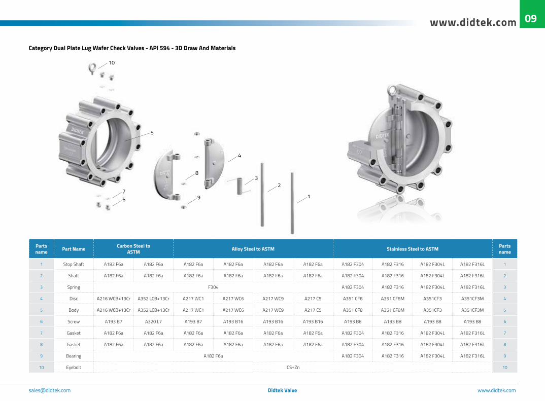
Dual Plate Lug Wafer Check ValveCategory Dual Plate Lug Wafer Check Valves - API 594 - Specification 08Category Dual Plate Lug Wafer Check Valves - API 594 - 3D Draw And Materials 09Category Dual Plate Lug Wafer Check Valves - API 594 - Lug Wafer Check Valves Picture 10Category Dual Plate Lug Wafer Check Valves - API 594 - Table Of Available Dimensions 11
Dual Plate Flange Wafer Check ValveCategory Dual Plate Flange Wafer Check Valves - API 594 - Specification 13Category Dual Plate Flange Wafer Check Valves - API 594 - 3D Draw And Materials 14Category Dual Plate Flange Wafer Check Valves - API 594 - Flange Wafer Check Valves Picture 15Category Dual Plate Flange Wafer Check Valves - API 594 - Table Of Available Dimensions 16
Lift Wafer Check ValveCategory Lift Wafer Check Valves - API 594 - Specification 17Category Lift Wafer Check Valves - API 594 - 3D Draw And Materials 18Category Lift Wafer Check Valves - API 594 - Lift Wafer Check Valves Picture 19Category Lift Wafer Check Valves - API 594 - Table Of Available Dimensions 20
Single Plate Wafer Check ValveCategory Single Plate Wafer Check Valves - API 594 - Specification 21Category Single Wafer Check Valves - API 594 - 3D Draw And Materials 22Category Single Plate Wafer Check Valves - API 594 - Single Plate Check Valves Picture 23Category Single Plate Wafer Check Valves - API 594 - Table Of Available Dimensions 24
Basic Data:Flanges ASME B 16.5 25Flanges ASME B 16.47 27Butt Weld ASME B 16.25 28Pressure Temperature Ratings 29
Content

[email protected] Didtek Valve www.didtek.com
Dual Plate Wafer Check ValveFigure:DIDTEKDPWCVDidtek Dual Plate Wafer Check Valve are manufactured to the lat-est editionof API Standard 594 and tested to API Standard 598.Application & Function:Didtek Dual Plate wafer check valve is a general purpose or high-performance check valve with a short face-to-face design. Unlike swing check valves, these valves are typically flangeless, installed between two flanges on the inside diameter of the flange bolt circle, held in place by studs. Spring tension can be custom-ized to accommodate low, minimum, standard, or high torque springs. Additionally, seating surfaces of a wafer check valve can be specified to meet service demands with such materials as Buna-N, Viton, Teflon, Neoprene, EPDM, and Hypalon for bub-ble-tight seating. Dual wafer check valve is commonly known as a dual disc check valve or dual check valve. They are spring-loaded and operate equally well in horizontal or vertical positions. Compatible body and disc material are offered in a wide variety of alloys for specific
applications. Alloys include bronze, carbon steel, Inconel, X-750, Inconel 600, Monel, Hastelloy C, and 17-7 PH.Applicable Standards:- Wafer Check Valve design according to API 594, API 6D- Face to face ASME B16.10/API 594- End Flanges ASME B16.5/ASME B16.47- Buttwelding ends ASME B16.25- Inspection and test API 598Pressure Rating:- ASME CL,150,300,600,900,1500,2500Temperature Range:- -50°C~650°CSize Range:
- 2’’~60’’
Category Dual Plate Wafer Check Valves - API 594-Specification
Design Description:
- Light and Compact
- “Zero Leakage” Sealing Design with Soft Seated
- Non Slam Design
- Installed in the horizontal and vertical up positions
- Discs open 85° to ensure a low pressure drop.
- Positive sealing under most operating conditions.
- Bubble Tight Close Off
Metal Seat DesignMetal seats include a full penetrate weld overlay of Stainless steel, Stellite 6 and so on.
Stable Performance SpringsStable Performance Springs allow higher torque to be exerted on each plate, with independent closure in response to process medium.
Thruse WashersMetal top and bottom thrust washers reduce friction and wear of valve plate hinges
Plate DesignDual plates pivot on a central vertical shaft.As flow begins the heel of the plates open first, this prevents scrubbing of the sealing surface. When plates are fully open the disc will open to 85°to ensure positive closing.
1. In standard or competitive designs, our manufactory drill four holes through the body of the check valve to facilitate the installation of a hinge pin and stop pin. The valves are sealed by four plugs.
2. Moreover internal stop pin and hinge pin which are machined into the cavity of the body wall. This design eliminates a potential shell or body leak path.
Soft Seat DesignResilient seats are standard and maintain positive shut-off.Seats are vulcanized to the body for maximun secruity.
1
2
Disc Open to 85°
02

[email protected] Didtek Valve www.didtek.com
www.didtek.com
Category Dual Plate Wafer Check Valves - API 594-3D Draw And Materials
Parts name Part Name Carbon Steel to
ASTM Alloy Steel to ASTM Stainless Steel to ASTM Parts name
1 Stop Shaft A182 F6a A182 F6a A182 F6a A182 F6a A182 F6a A182 F6a A182 F304 A182 F316 A182 F304L A182 F316L 1
2 Shaft A182 F6a A182 F6a A182 F6a A182 F6a A182 F6a A182 F6a A182 F304 A182 F316 A182 F304L A182 F316L 2
3 Spring F304 A182 F304 A182 F316 A182 F304L A182 F316L 3
4 Disc A216 WCB+13Cr A352 LCB+13Cr A217 WC1 A217 WC6 A217 WC9 A217 C5 A351 CF8 A351 CF8M A351CF3 A351CF3M 4
5 Body A216 WCB+13Cr A352 LCB+13Cr A217 WC1 A217 WC6 A217 WC9 A217 C5 A351 CF8 A351 CF8M A351CF3 A351CF3M 5
6 Screw A193 B7 A320 L7 A193 B7 A193 B16 A193 B16 A193 B16 A193 B8 A193 B8 A193 B8 A193 B8 6
7 Gasket A182 F6a A182 F6a A182 F6a A182 F6a A182 F6a A182 F6a A182 F304 A182 F316 A182 F304L A182 F316L 7
8 Gasket A182 F6a A182 F6a A182 F6a A182 F6a A182 F6a A182 F6a A182 F304 A182 F316 A182 F304L A182 F316L 8
9 Bearing A182 F6a A182 F304 A182 F316 A182 F304L A182 F316L 9
10 Eye Screw CS+Zn 10
17
6
10
2
3
4
8
5
9
03

[email protected] Didtek Valve www.didtek.com
Category Dual Plate Wafer Check Valves - API 594-Wafer Check Valves Picture
04

[email protected] Didtek Valve www.didtek.com
www.didtek.com
Valve Size
ASME B16.47-A
28” 30” 32” 36” 40” 42” 48” 54” 60”
ASME B16.47-B
28” 30” 32” 36” 40” 42” 48” 54” 60”
700mm
750mm
800mm
900mm
1000mm
1050mm
1200mm
1350mm
1500mm
700mm
750mm
800mm
900mm
1000mm
1050mm
1200mm
1350mm
1500mm
Face to Face L 305 305 305 368 432 432 524 591 660 305 305 305 368 432 432 524 591 660
Valve Dimensions
D 827 878 935 1045 1158 1213 1397 1545 1710 773 824 878 983 1090 1142 1302 1460 1628
D2 685 735 785 885 980 1020 1170 1315 1460 685 740 785 885 980 1020 1170 1315 1460
D3 690 740 790 890 990 1040 1180 1330 1470 690 740 790 890 990 1040 1180 1330 1470
Weight(Kg) 390 440 530 700 920 980 1580 2480 3500 350 400 450 620 820 880 1420 2230 3150
Valve Size2” 2-1/2” 3” 4” 5” 6” 8” 10” 12” 14” 16” 18” 20” 24”
50mm 65mm 80mm 100mm 125mm 150mm 200mm 250mm 300mm 350mm 400mm 450mm 500mm 600mm
Face to Face L 60 67 73 73 86 98 127 146 181 184 191 203 219 222
Valve Dimensions
D 103 122 135 173 195 220 277 337 407 448 512 547 604 715
D2 51 65 80 102 127 152 203 254 305 350 400 450 500 600
D3 58 73 88 108 132 160 210 265 310 355 405 455 505 605
Weight(Kg) 2 3 4 6 9 9 24 36 60 85 120 140 160 250
150LB
150LB
300LB
D2 DD3
L
D2 DD3
L
D2 DD3
L
Valve Size2” 2-1/2” 3” 4” 5” 6” 8” 10” 12” 14” 16” 18” 20” 24”
50mm 65mm 80mm 100mm 125mm 150mm 200mm 250mm 300mm 350mm 400mm 450mm 500mm 600mm
Face to Face L 60 67 73 73 86 98 127 146 181 184 232 264 292 318
Valve Dimensions
D 110 128 147 179 214 249 305 359 420 483 537 594 652 772
D2 51 65 80 102 127 152 203 254 305 350 400 450 500 600
D3 58 73 88 108 132 160 210 265 310 355 405 455 505 605
Weight(Kg) 3 4 6 8 13 13 32 51 78 135 185 230 300 430
Category Dual Plate Wafer Check Valves - API 594-Table Of Available Dimensions
05

[email protected] Didtek Valve www.didtek.com
06
Valve Size
ASME B16.47-A
28” 30” 32” 36” 40” 42” 48” 54” 60”
ASME B16.47-B
28” 30” 32” 36” 40” 42” 48” 54” 60”
700mm
750mm
800mm
900mm
1000mm
1050mm
1200mm
1350mm
1500mm
700mm
750mm
800mm
900mm
1000mm
1050mm
1200mm
1350mm
1500mm
Face to Face L 368 368 368 483 546 568 629 718 838 368 368 368 483 546 568 629 718 838
Valve Dimensions
D 895 949 1003 1113 1110 1161 1320 1489 1642 821 882 936 1044 1146 1196 1365 1526 1704
D2 685 735 785 885 980 1020 1170 1315 1460 685 735 785 880 980 1020 1170 1315 1460
D3 690 740 790 890 990 1040 1180 1330 1470 690 740 790 890 990 1040 1180 1330 1470
Weight(Kg) 680 700 760 1180 1480 1600 2250 3200 4800 600 630 680 1080 1300 1450 2030 2900 4300
300LB
600LB
600LB
D2 DD3
L
D2 DD3
L
D2 DD3
L
Valve Size2” 2-1/2” 3” 4” 5” 6” 8” 10” 12” 14” 16” 18” 20” 24”
50mm 65mm 80mm 100mm 125mm 150mm 200mm 250mm 300mm 350mm 400mm 450mm 500mm 600mm
Face to Face L 60 67 73 79 105 136 165 213 229 273 305 362 368 438
Valve
Dimensions
D 110 128 147 191 239 265 318 398 455 490 562 610 680 786
D2 51 65 80 102 127 152 200 254 305 340 390 440 490 590
D3 58 73 88 108 132 160 210 265 310 350 400 450 500 600
Weight(Kg) 3 5 7 11 20 30 55 110 150 215 320 390 520 780
Valve SizeASM
E B16.47-A
28” 30” 32” 36” 40” 42” 48”
ASME B16.47-B
28” 30” 32” 36”
700mm 750mm 800mm 900mm 1000mm 1050mm 1200mm 700mm 750mm 800mm 900mm
Face to Face L 483 505 533 635 660 702 787 483 505 533 635
Valve
Dimensions
D 910 967 1020 1126 1153 1215 1386 815 875 928 1045
D2 685 735 780 875 980 1020 1170 685 735 780 875
D3 690 740 790 880 985 1030 1170 690 740 790 880
Weight(Kg) 1250 1550 1800 2200 2600 2900 4050 1000 1280 1500 1900
Category Dual Plate Wafer Check Valves - API 594-Table Of Available Dimensions

[email protected] Didtek Valve www.didtek.com
www.didtek.com 07
D2 DD3
L
P
F
E23°
I
I
D2 DD3
L
P
F
E23°
I
I
D2 DD3
L
P
F
E23°
I
I
Valve Size2” 2-1/2” 3” 4” 5” 6” 8” 10” 12” 14” 16” 18” 20” 24”
50mm 65mm 80mm 100mm 125mm 150mm 200mm 250mm 300mm 350mm 400mm 450mm 500mm 600mm
Face to Face L 70 83 83 102 110 159 206 241 292 356 384 451 451 495
Valve Dimensions
D 140 162 165 204 245 286 356 432 495 518 572 635 695 835
D2 50 62 76 100 125 150 200 250 300 340 380 430 490 580
P 95.25 107.95 123.83 149.23 180.98 211.12 269.88 323.85 381 419.1 469.9 533.4 584.2 692.15
E 7.92 7.92 7.92 7.92 7.92 7.92 7.92 7.92 7.92 11.13 11.13 12.7 12.7 15.88
F 11.91 11.91 11.91 11.91 11.91 11.91 11.91 11.91 11.91 16.66 16.66 19.84 19.84 26.97
D3 55 70 88 108 130 160 210 265 305 350 400 440 500 590
Weight(Kg) 8 11 12 19 33 48 85 180 270 350 470 605 820 1050
900LB
1500LB
2500LB
Valve Size2” 2-1/2” 3” 4” 5” 6” 8” 10” 12” 14” 16” 18” 20” 24”
50mm 65mm 80mm 100mm 125mm 150mm 200mm 250mm 300mm 350mm 400mm 450mm 500mm 600mm
Face to Face L 70 83 83 102 110 159 206 248 305 356 384 468 533 559
Valve Dimensions
D 140 162 172 207 252 280 350 433 518 576 639 701 752 898
D2 50 62 76 100 125 150 200 240 300 330 370 420 460 560
P 95.25 107.95 136.53 161.93 193.68 211.14 269.88 323.85 381 419.1 469.9 533.4 584.2 692.15
E 7.92 7.92 7.92 7.92 7.92 9.53 11.13 11.13 14.27 15.88 17.48 17.48 17.48 20.62
F 11.91 11.91 11.91 11.91 11.91 13.49 16.66 16.66 23.01 26.97 30.18 30.18 33.32 36.53
D3 55 70 88 108 130 160 210 260 305 340 390 440 480 570
Weight(Kg) 8 11 13 24 35 60 130 220 390 570 750 1000 1280 1950
Valve Size2” 2-1/2” 3” 4” 5” 6” 8” 10” 12”
50mm 65mm 80mm 100mm 125mm 150mm 200mm 250mm 300mm
Face to Face L 70 83 86 105 110 159 206 254 305
Valve Dimensions
D 143 166 194 232 277 315 385 474 547
D2 45 52 65 90 110 135 180 225 270
P 95.25 111.13 127 157.16 190.5 247.65 279.4 342.9 406.4
E 7.92 9.6 9.6 11.2 12.7 6.4 14.3 17.5 17.5
F 11.91 13.49 13.49 16.67 19.84 8.73 23.02 30.16 33.34
D3 50 60 85 100 120 150 190 235 280
Weight(Kg) 9 13 19 32 47 86 170 240 450
Category Dual Plate Wafer Check Valves - API 594-Table Of Available Dimensions

[email protected] Didtek Valve www.didtek.com
Figure:DIDTEKDPLWCVDidtek Dual Plate Lug Wafer Check Valve are manufactured to the latest editionof API Standard 594 and tested to API Standard 598.Application & Function:Didtek Dual Plate Lug wafer check valve is a general purpose or high-performance check valve with a short face-to-face design. Unlike swing check valves, these valves are typically flangeless, installed between two flanges on the inside diameter of the flange bolt circle, held in place by studs. Spring tension can be custom-ized to accommodate low, minimum, standard, or high torque springs. Additionally, seating surfaces of a wafer check valve can be specified to meet service demands with such materials as Buna-N, Viton, Teflon, Neoprene, EPDM, and Hypalon for bub-ble-tight seating. Didtek Dual Plate Lug Wafer Check Valve is commonly known as a dual disc check valve or dual check valve. They are spring-loaded and operate equally well in horizontal or vertical positions. Com-
patible body and disc material are offered in a wide variety of al-loys for specific applications. Alloys include bronze, carbon steel, Inconel, X-750, Inconel 600, Monel, Hastelloy C, and 17-7 PH.Applicable Standards:- Wafer Check Valve design according to API 594, API 6D- Face to face ASME B16.10/API 594- End Flanges ASME B16.5/ASME B16.47- Buttwelding ends ASME B16.25- Inspection and test API 598Pressure Rating:- ASME CL,150,300,600,900,1500,2500Temperature Range:- -50°C~650°CSize Range- 2’’~24’’
Category Dual Plate Lug Wafer Check Valves - API 594 - Specification
Dual Plate Lug Wafer Check Valve
Design Description:
- Light and Compact
- “Zero Leakage” Sealing Design with Soft Seated
- Non Slam Design
- Installed in the horizontal and vertical up positions
- Discs open 85° to ensure a low pressure drop.
- Positive sealing under most operating conditions.
- Bubble Tight Close Off
Metal Seat DesignMetal seats include a full penetrate weld overlay of Stainless steel, Stellite 6 and so on.
Stable Performance SpringsStable Performance Springs allow higher torque to be exerted on each plate, with independent closure in response to process medium.
Thruse WashersMetal top and bottom thrust washers reduce friction and wear of valve plate hinges
Plate DesignDual plates pivot on a central vertical shaft.As flow begins the heel of the plates open first, this prevents scrubbing of the sealing surface. When plates are fully open the disc will open to 85°to ensure positive closing.
1. In standard or competitive designs, our manufactory drill four holes through the body of the check valve to facilitate the installation of a hinge pin and stop pin. The valves are sealed by four plugs.
2. Moreover internal stop pin and hinge pin which are machined into the cavity of the body wall. This design eliminates a potential shell or body leak path.
Soft Seat DesignResilient seats are standard and maintain positive shut-off.Seats are vulcanized to the body for maximun secruity.
1
2
Disc Open to 85°
08
[email protected] Didtek Valve www.didtek.com
www.didtek.com
Category Dual Plate Lug Wafer Check Valves - API 594 - 3D Draw And Materials
5
1
23
4
8
976
10
Parts name Part Name Carbon Steel to
ASTM Alloy Steel to ASTM Stainless Steel to ASTM Parts name
1 Stop Shaft A182 F6a A182 F6a A182 F6a A182 F6a A182 F6a A182 F6a A182 F304 A182 F316 A182 F304L A182 F316L 1
2 Shaft A182 F6a A182 F6a A182 F6a A182 F6a A182 F6a A182 F6a A182 F304 A182 F316 A182 F304L A182 F316L 2
3 Spring F304 A182 F304 A182 F316 A182 F304L A182 F316L 3
4 Disc A216 WCB+13Cr A352 LCB+13Cr A217 WC1 A217 WC6 A217 WC9 A217 C5 A351 CF8 A351 CF8M A351CF3 A351CF3M 4
5 Body A216 WCB+13Cr A352 LCB+13Cr A217 WC1 A217 WC6 A217 WC9 A217 C5 A351 CF8 A351 CF8M A351CF3 A351CF3M 5
6 Screw A193 B7 A320 L7 A193 B7 A193 B16 A193 B16 A193 B16 A193 B8 A193 B8 A193 B8 A193 B8 6
7 Gasket A182 F6a A182 F6a A182 F6a A182 F6a A182 F6a A182 F6a A182 F304 A182 F316 A182 F304L A182 F316L 7
8 Gasket A182 F6a A182 F6a A182 F6a A182 F6a A182 F6a A182 F6a A182 F304 A182 F316 A182 F304L A182 F316L 8
9 Bearing A182 F6a A182 F304 A182 F316 A182 F304L A182 F316L 9
10 Eyebolt CS+Zn 10
09

[email protected] Didtek Valve www.didtek.com
Category Dual Plate Lug Wafer Check Valves - API 594 - Lug Wafer Check Valves Picture
10

[email protected] Didtek Valve www.didtek.com
www.didtek.com 11R D3
D2
L
n-Ød
D1
R D3
D2
L
n-Ød
D1
R D3
D2
L
n-Ød
D1
150LB
300LB
600LB
Valve Size2” 2-1/2” 3” 4” 5” 6” 8” 10” 12” 14” 16” 18” 20” 24”
50mm 65mm 80mm 100mm 125mm 150mm 200mm 250mm 300mm 350mm 400mm 450mm 500mm 600mm
Face to Face L 60 67 73 73 86 98 127 146 181 184 191 203 219 222
Valve Dimensions
D1 120.7 139.7 152.4 190.5 215.9 241.3 298.5 362 431.8 476.3 539.8 577.9 635 749.3
R 92 105 127 157 186 216 270 324 381 413 470 533 584 692
n-∅d 4-∅19 4-∅19 4-∅19 8-∅19 8-∅22 8-∅22 8-∅22 12-∅25 12-∅25 12-∅29 16-∅29 16-∅32 20-∅32 20-∅35
D2 51 65 80 102 127 152 203 254 305 350 400 450 500 600
D3 58 73 88 108 132 160 210 265 310 360 410 460 510 610
Weight(Kg) 4 5.5 7 11 15 19 36 60 115 130 180 205 280 330
Valve Size2” 2-1/2” 3” 4” 5” 6” 8” 10” 12” 14” 16” 18” 20” 24”
50mm 65mm 80mm 100mm 125mm 150mm 200mm 250mm 300mm 350mm 400mm 450mm 500mm 600mm
Face to Face L 60 67 73 73 86 98 127 146 181 222 232 264 292 318
Valve Dimensions
D1 127 149.2 168.3 200 235 269.9 330.2 387.4 450.8 514.4 571.5 628.6 685.8 812.8
R 92 105 127 157 186 216 270 324 381 413 470 533 584 692
n-∅d 8-∅19 8-∅22 8-∅22 8-∅22 8-∅22 12-∅22 12-∅25 16-∅29 16-∅32 20-∅32 20-∅35 24-∅35 24-∅35 24-∅41
D2 51 65 80 102 127 152 203 254 305 350 400 450 500 600
D3 58 73 88 108 132 160 210 265 310 360 410 460 510 610
Weight(Kg) 6 7 10 16 26 32 62 82 160 260 342 400 540 833
Category Dual Plate Lug Wafer Check Valves - API 594 - Table Of Available Dimensions

[email protected] Didtek Valve www.didtek.com
12
Valve Size2” 2-1/2” 3” 4” 5” 6” 8” 10” 12” 14” 16” 18” 20” 24”
50mm 65mm 80mm 100mm 125mm 150mm 200mm 250mm 300mm 350mm 400mm 450mm 500mm 600mm
Face to Face L 70 83 83 102 110 159 206 241 292 356 384 451 451 495
Valve Dimensions
D1 165.1 190.5 190.5 235 279.4 317.5 393.7 469.9 533.4 558.8 616 685.8 749.3 901.7
R 124 137 156 181 216 241 308 362 419 467 524 594 648 772
n-∅d 8-∅25 8-∅29 8-∅25 8-∅32 8-∅35 12-∅32 12-∅38 16-∅38 20-∅38 20-∅41 20-∅44 20-∅51 20-∅54 20-∅67
P 95.25 107.95 123.83 149.23 180.98 211.12 269.88 323.85 381 419.1 469.9 533.4 584.2 692.15
E 7.92 7.92 7.92 7.92 7.92 7.92 7.92 7.92 7.92 11.13 11.13 12.7 12.7 15.88
F 11.91 11.91 11.91 11.91 11.91 11.91 11.91 11.91 11.91 16.66 16.66 19.84 19.84 26.97
D2 50 62 76 100 125 150 200 250 300 340 380 430 490 580
D3 55 70 88 108 130 160 210 265 310 350 400 440 500 590
Weight(Kg) 15 23 23 42 80 105 220 280 480 720 780 1180 1600 1950
900LB
1500LB
R D3
D2
L
n-Ød
PD1
I
F
E23°
I
R D3
D2
L
n-Ød
PD1
I
F
E23°
I
Valve Size2” 2-1/2” 3” 4” 5” 6” 8” 10” 12” 14” 16” 18” 20” 24”
50mm 65mm 80mm 100mm 125mm 150mm 200mm 250mm 300mm 350mm 400mm 450mm 500mm 600mm
Face to Face L 70 83 83 102 110 159 206 248 305 356 384 468 533 559
Valve Dimensions
D1 165.1 190.5 203.2 241.3 292.1 317.5 393.7 482.6 571.5 635 704.8 774.7 831.8 990.6
R 124 137 168 194 229 248 318 371 438 489 546 613 673 794
n-∅d 8-∅25 8-∅29 8-∅32 8-∅35 8-∅41 12-∅38 12-∅44 12-∅51 16-∅54 16-∅60 16-∅67 16-∅73 16-∅79 16-∅92
P 95.25 107.95 136.53 161.93 193.68 211.14 269.88 323.85 381 419.1 469.9 533.4 584.2 692.15
E 7.92 7.92 7.92 7.92 7.92 9.53 11.13 11.13 14.27 15.88 17.48 17.48 17.48 20.62
F 11.91 11.91 11.91 11.91 11.91 13.49 16.66 16.66 23.01 26.97 30.18 30.18 33.32 36.53
D2 50 62 76 100 125 150 200 240 300 330 370 420 460 560
D3 55 70 88 108 130 160 210 260 305 340 390 440 480 570
Weight(Kg) 15 23 25 45 95 115 230 330 600 905 1100 1700 1280 3000
Category Dual Plate Lug Wafer Check Valves - API 594 - Table Of Available Dimensions

[email protected] Didtek Valve www.didtek.com
www.didtek.com 13
Dual Plate Flange Wafer Check ValveFigure: DIDTEKDPFWCVDidtek Dual Plate Flange Wafer Check Valve are manufactured to the latest editionof API Standard 594 and tested to API Standard 598.
Application & Function:
Didtek Dual Plate Flange wafer check valve is a general purpose or high-performance check valve with a short face-to-face design. Unlike swing check valves, these valves are typically flangeless, installed be-tween two flanges on the inside diameter of the flange bolt circle, held in place by studs. Spring tension can be customized to accommodate low, minimum, standard, or high torque springs. Additionally, seating surfaces of a wafer check valve can be specified to meet service de-mands with such materials as Buna-N, Viton, Teflon, Neoprene, EPDM, and Hypalon for bubble-tight seating.
Didtek Dual Plate Flange wafer check valve is commonly known as a dual disc check valve or dual check valve. They are spring-loaded and operate equally well in horizontal or vertical positions. Compatible body and disc material are offered in a wide variety of alloys for specific
applications. Alloys include bronze, carbon steel, Inconel, X-750, Inconel 600, Mo-nel, Hastelloy C, and 17-7 PH.
Applicable Standards:- Wafer Check Valve design according to API 594, API 6D- Face to face ASME B16.10/API 594- End Flanges ASME B16.5/ASME B16.47- Buttwelding ends ASME B16.25- Inspection and test API 598Pressure Rating:- ASME CL,150,300,600,900,1500,2500Temperature Range:- -50°C~650°CSize Range:
- 2''~60''
Category Dual Plate Flange Wafer Check Valves - API 594 - Specification
Design Description:
- Light and Compact
- “Zero Leakage” Sealing Design with Soft Seated
- Non Slam Design
- Installed in the horizontal and vertical up positions
- Discs open 85° to ensure a low pressure drop.
- Positive sealing under most operating conditions.
- Bubble Tight Close Off
Metal Seat DesignMetal seats include a full penetrate weld overlay of Stainless steel, Stellite 6 and so on.
Stable Performance SpringsStable Performance Springs allow higher torque to be exerted on each plate, with independent closure in response to process medium.
Thruse WashersMetal top and bottom thrust washers reduce friction and wear of valve plate hinges
Plate DesignDual plates pivot on a central vertical shaft.As flow begins the heel of the plates open first, this prevents scrubbing of the sealing surface. When plates are fully open the disc will open to 85°to ensure positive closing.
1. In standard or competitive designs, our manufactory drill four holes through the body of the check valve to facilitate the installation of a hinge pin and stop pin. The valves are sealed by four plugs.
2. Moreover internal stop pin and hinge pin which are machined into the cavity of the body wall. This design eliminates a potential shell or body leak path.
Soft Seat DesignResilient seats are standard and maintain positive shut-off.Seats are vulcanized to the body for maximun secruity.
1
2
Disc Open to 85°

[email protected] Didtek Valve www.didtek.com
14
Category Dual Plate Flange Wafer Check Valves - API 594 - 3D Draw And Materials
12
3
4
5
7
10
6
8
9
Parts name Part Name Carbon Steel to
ASTM Alloy Steel to ASTM Stainless Steel to ASTM Parts name
1 Stop Shaft A182 F6a A182 F6a A182 F6a A182 F6a A182 F6a A182 F6a A182 F304 A182 F316 A182 F304L A182 F316L 1
2 Shaft A182 F6a A182 F6a A182 F6a A182 F6a A182 F6a A182 F6a A182 F304 A182 F316 A182 F304L A182 F316L 2
3 Spring F304 A182 F304 A182 F316 A182 F304L A182 F316L 3
4 Disc A216 WCB+13Cr A352 LCB+13Cr A217 WC1 A217 WC6 A217 WC9 A217 C5 A351 CF8 A351 CF8M A351CF3 A351CF3M 4
5 Body A216 WCB+13Cr A352 LCB+13Cr A217 WC1 A217 WC6 A217 WC9 A217 C5 A351 CF8 A351 CF8M A351CF3 A351CF3M 5
6 Screw A193 B7 A320 L7 A193 B7 A193 B16 A193 B16 A193 B16 A193 B8 A193 B8 A193 B8 A193 B8 6
7 Gasket A182 F6a A182 F6a A182 F6a A182 F6a A182 F6a A182 F6a A182 F304 A182 F316 A182 F304L A182 F316L 7
8 Gasket A182 F6a A182 F6a A182 F6a A182 F6a A182 F6a A182 F6a A182 F304 A182 F316 A182 F304L A182 F316L 8
9 Bearing A182 F6a A182 F304 A182 F316 A182 F304L A182 F316L 9
10 Eyebolt CS+Zn 10

[email protected] Didtek Valve www.didtek.com
www.didtek.com 15
Category Dual Plate Flange Wafer Check Valves - API 594 - Flange Wafer Check Valves Picture

[email protected] Didtek Valve www.didtek.com
16
D2
L
D3
D2
L
D3
D2
L
D3
150LB
300LB
600LB
900LB
D2
L
D3
F
E23°
I
I
Valve Size8” 10” 12” 14” 16” 18” 20” 24” 28” 30” 32” 36” 40” 42” 48” 54” 60”
200mm 250mm 300mm 350mm 400mm 450mm 500mm 600mm 700mm 750mm 800mm 900mm 1000mm 1050mm 1200mm 1350mm 1500mm
Face to Face L 127 146 181 184 191 203 219 222 305 305 305 368 432 432 524 591 660
Valve Dimensions
D2 203 254 305 350 400 450 500 600 685 735 785 885 980 1020 1170 1315 1460
D3 210 265 310 355 405 455 505 605 690 740 790 890 990 1040 1190 1330 1470
Weight(Kg) 42 65 100 135 168 205 260 370 700 760 990 - - - - - -
Valve Size10” 12” 14” 16” 18” 20” 24” 28” 30” 32” 36” 40” 42” 48” 54” 60”
250mm 300mm 350mm 400mm 450mm 500mm 600mm 700mm 750mm 800mm 900mm 1000mm 1050mm 1200mm 1350mm 1500mm
Face to Face L 146 181 222 232 264 292 318 368 368 368 483 546 568 629 718 838
Valve Dimensions
D2 254 305 350 400 450 500 600 685 735 785 885 980 1020 1170 1315 1460
D3 265 310 355 405 455 505 605 690 740 790 890 990 1040 1180 1330 1470
Weight(Kg) 85 155 210 310 380 450 720 - - - - - - - - -
Valve Size10” 12” 14” 16” 18” 20” 24” 28” 30” 32” 36” 40”
250mm 300mm 350mm 400mm 450mm 500mm 600mm 700mm 750mm 800mm 900mm 1000mm
Face to Face L 213 229 273 305 362 368 438 483 505 533 635 660
Valve Dimensions
D2 254 305 340 390 440 490 590 685 735 780 875 980
D3 265 310 350 400 450 500 600 690 740 790 880 985
Weight(Kg) 185 240 380 500 620 780 1120 - - - - -
Valve Size10” 12” 14” 16” 18” 20” 24” 28” 30” 32” 36” 40”
250mm 300mm 350mm 400mm 450mm 500mm 600mm 700mm 750mm 800mm 900mm 1000mm
Face to Face L 241 292 356 384 451 451 495 572 635 660 718 762
Valve Dimensions
D2 250 305 340 380 430 490 580 670 715 760 855 950
D3 265 310 350 400 440 500 590 680 730 780 865 965
Weight(Kg) 210 350 470 630 880 1800 2000 - - - - -
Category Dual Plate Flange Wafer Check Valves - API 594 - Table Of Available Dimensions

[email protected] Didtek Valve www.didtek.com
www.didtek.com 1717
Lift Wafer Check ValveFigure: DIDTEKLWCVDidtek Lift Wafer Check Valve are manufactured to the latest editionof API Standard 594 and tested to API Standard 598.
Application & Function:
Didtek Lift wafer check valve is a general purpose or high-performance check valve with a short face-to-face design. Unlike swing check valves, these valves are typically flangeless, installed between two flanges on the inside diameter of the flange bolt circle, held in place by studs. Spring tension can be customized to accommodate low, mini-mum, standard, or high torque springs. Additionally, seating surfaces of a wafer check valve can be specified to meet service demands with such materials as Buna-N, Viton, Teflon, Neoprene, EPDM, and Hyp-alon for bubble-tight seating.
Didtek Lift wafer check valve is commonly known as a wafer check valve or Lift check valve. They are spring-loaded and operate equally well in horizontal or vertical positions. Compatible body and disc ma-terial are offered in a wide variety of alloys for specific applications. Alloys include bronze, carbon steel, Inconel, X-750, Inconel 600, Monel,
Hastelloy C, and 17-7 PH.
Applicable Standards:- Wafer Check Valve design according to API 594, API 6D- Face to face ASME B16.10/API 594- End Flanges ASME B16.5/ASME B16.47- Inspection and test API 598Pressure Rating:
- ASME CL,150,300,600,900
Temperature Range:
- -50°C~650°C
Size Range:
- 1/2’’~8’’
Metal Seat DesignMetal seats include a full penetrate weld overlay of Stainless steel, Stellite 6 and so on.
Soft Seat DesignResilient seats are standard and maintain positive shut-off.Seats are vulcanized to the body for maximun secruity.
Design Description:
- Light and Compact
- “Zero Leakage” Sealing Design with Soft Seated
- Installed in the horizontal and vertical up positions
- Positive sealing under most operating conditions.
- Long-lasting service with superior performance
Category Lift Wafer Check Valves - API 594 - Specification

[email protected] Didtek Valve www.didtek.com
18
Category Lift Wafer Check Valves - API 594 - 3D Draw And Materials
12
3
4
Parts name Part Name Carbon Steel to ASTM Alloy Steel to ASTM Stainless Steel to ASTM Parts
name
1 Guide Sleeve A216 WCB+13Cr A352 LCB+13Cr A217 WC1 A217 WC6 A217 WC9 A217 C5 A351 CF8 A351 CF8M A351CF3 A351CF3M 1
2 Spring A182 F6a A182 F6a A182 F6a A182 F6a A182 F6a A182 F6a A182 F304 A182 F316 A182 F304L A182 F316L 2
3 Disc A216 WCB+13Cr A352 LCB+13Cr A217 WC1 A217 WC6 A217 WC9 A217 C5 A351 CF8 A351 CF8M A351CF3 A351CF3M 3
4 Body A216 WCB+13Cr A352 LCB+13Cr A217 WC1 A217 WC6 A217 WC9 A217 C5 A351 CF8 A351 CF8M A351CF3 A351CF3M 4

[email protected] Didtek Valve www.didtek.com
www.didtek.com 1919
Category Lift Wafer Check Valves - API 594 - Lift Wafer Check Valves Picture

[email protected] Didtek Valve www.didtek.com
Valve Size1/2” 3/4” 1” 1-1/4” 1-1/2” 2” 2-1/2” 3” 4” 5” 6” 8”
15mm 20mm 25mm 32mm 40mm 50mm 65mm 80mm 100mm 125mm 150mm 200mm
Face to Face L 25 31.5 35.5 40 45 56 63 71 80 110 125 160
Valve Dimensions
D 46 56 65 74 84 103 122 135 173 195 220 277
D2 15 19 24 31 38 48 62 76 90 110 127 165
D3 23 28 34 42 50 60 78 91 110 135 160 210
Weight(Kg) 0.3 0.45 0.6 0.8 1.3 2.1 2.8 3.6 4.8 12 17 29
D2
D3D
L L
D2
D3D
150LB
Valve Size1/2” 3/4” 1” 1-1/4” 1-1/2” 2” 2-1/2” 3” 4” 5” 6” 8”
15mm 20mm 25mm 32mm 40mm 50mm 65mm 80mm 100mm 125mm 150mm 200mm
Face to Face L 25 31.5 35.5 40 45 56 63 71 80 110 125 160
Valve Dimensions
D 52 65 72 81 94 110 128 147 179 214 249 305
D2 15 19 24 31 38 48 62 76 90 110 127 165
D3 23 28 34 42 50 60 78 91 110 135 160 210
Weight(Kg) 0.35 0.5 0.7 0.9 1.5 2.4 3 4 5.5 13 22 36
D2
D3D
L L
D2
D3D
300LB
Valve Size1/2” 3/4” 1” 1-1/4” 1-1/2” 2” 2-1/2” 3” 4” 5” 6” 8”
15mm 20mm 25mm 32mm 40mm 50mm 65mm 80mm 100mm 125mm 150mm 200mm
Face to Face L 25 31.5 35.5 40 45 56 63 71 80 110 125 160
Valve Dimensions
D 52 65 72 81 94 110 128 147 191 239 265 318
D2 15 19 24 31 38 48 62 76 90 110 127 165
D3 23 28 34 42 50 60 78 91 110 135 160 210
Weight(Kg) 0.4 0.8 1 1.3 1.8 2.8 4 6 9 25 32 52
D2
D3D
L L
D2
D3D
600LB
Valve Size1/2” 3/4” 1” 1-1/4” 1-1/2” 2” 2-1/2” 3” 4” 5” 6” 8”
15mm 20mm 25mm 32mm 40mm 50mm 65mm 80mm 100mm 125mm 150mm 200mm
Face to Face L 25 31.5 35.5 40 45 56 63 71 80 110 125 160
Valve Dimensions
D 62 69 77 87 97 140 162 165 204 245 286 356
D2 15 19 24 31 38 48 62 76 90 110 127 165
D3 23 28 34 42 50 60 78 91 110 135 160 210
Weight(Kg) 0.6 0.9 1.2 1.5 2 5.5 7.5 8 14 27 41 76
D2
D3D
L L
D2
D3D
900LB
Category Lift Wafer Check Valves - API 594 - Table Of Available Dimensions
20

[email protected] Didtek Valve www.didtek.com
www.didtek.com
Single Plate Wafer Check ValveFigure: DIDTEKSPWCVDidtek Single Plate Wafer Check Valve are manufactured to the latest editionof API Standard 594 and tested to API Standard 598.Application & Function:Didtek Single Plate wafer check valve is a general purpose or high-per-formance check valve with a short face-to-face design. Unlike swing check valves, these valves are typically flangeless, installed between two flanges on the inside diameter of the flange bolt circle, held in place by studs. Spring tension can be customized to accommodate low, min-imum, standard, or high torque springs. Additionally, seating surfaces of a wafer check valve can be specified to meet service demands with such materials as Buna-N, Viton, Teflon, Neoprene, EPDM, and Hyp-alon for bubble-tight seating. Compatible body and disc material are offered in a wide variety of al-loys for specific applications. Alloys include bronze, carbon steel, Inco-nel, X-750, Inconel 600, Monel, Hastelloy C, and 17-7 PH.Applicable Standards:- Wafer Check Valve design according to API594, API6D- Face to face ANSI B16.10/API 594
- End Flanges ASME B16.5- Inspection and test API 598Pressue Rating:- ASME CL,150,300,600Temperature Range:- -50°C~650°C
Size Range:
- 2’’~20’’
Metal Seat DesignMetal seats include a full penetrate weld overlay of Stainless steel, Stellite 6 and so on.
Soft Seat DesignResilient seats are standard and maintain positive shut-off.Seats are vulcanized to the body for maximun secruity.
Design Description:
- Light and Compact
- “Zero Leakage” Sealing Design with Soft Seated
- Installed in the horizontal and vertical up positions
- Positive sealing under most operating conditions.
- Long-lasting service with superior performance
Category Single Plate Wafer Check Valves - API 594 - Specification
21

[email protected] Didtek Valve www.didtek.com
Category Single Wafer Check Valves - API 594 - 3D Draw And Materials
Parts name Part Name Carbon Steel to ASTM Stainless Steel to ASTM Parts
name
1 Body A105+13Cr A182 F304 A182 F316 1
2 Disc A105+13Cr A182 F304 A182 F316 2
3 Located Block A105 A182 F304 A182 F316 3
4 Screw A105 A182 F304 A182 F316 4
5 Eyebolt Carbon Steel Stainless Steel 5
1
5
23
4
22

[email protected] Didtek Valve www.didtek.com
www.didtek.com
Category Single Plate Wafer Check Valves - API 594 - Single Plate Check Valves Picture
23

[email protected] Didtek Valve www.didtek.com
Valve Size2” 2-1/2” 3” 4” 6” 8” 10” 12” 14” 16” 18” 20”
50mm 65mm 80mm 100mm 150mm 200mm 250mm 300mm 350mm 400mm 450mm 500mm
Face to Face L 19 19 19 19 22 29 38 51 51 51 76 83
Valve Dimensions
d 25 38 46 72 114 140 188 216 263 305 356 406
D 110 128 147 179 249 305 359 420 483 537 594 652
Weight(Kg) 1.3 1.8 2.2 3.5 6.5 14 20 40 53 70 125 160
dD
L
dD
L
dD
L
150LB
Valve Size2” 2-1/2” 3” 4” 6” 8” 10” 12” 14” 16” 18” 20”
50mm 65mm 80mm 100mm 150mm 200mm 250mm 300mm 350mm 400mm 450mm 500mm
Face to Face L 19 19 19 19 19 29 29 38 44 51 60 64
Valve Dimensions
d 25 38 46 72 114 140 188 216 263 305 356 406
D 103 122 135 173 220 277 337 407 448 512 547 604
Weight(Kg) 1.2 1.7 2 3 5.5 12 16 27 42 62 78 110
300LB
600LB
Valve Size2” 2-1/2” 3” 4” 6” 8” 10” 12” 14” 16” 18” 20”
50mm 65mm 80mm 100mm 150mm 200mm 250mm 300mm 350mm 400mm 450mm 500mm
Face to Face L 19 19 19 22 28 38 57 60 67 73 83 92
Valve Dimensions
d 25 38 46 72 114 140 188 216 263 305 356 406
D 110 128 147 191 264 318 398 455 490 562 610 680
Weight(Kg) 1.3 1.8 2.2 4 8 18 45 60 75 108 135 190
Category Single Plate Wafer Check Valves - API 594 - Table Of Available Dimensions
24

[email protected] Didtek Valve www.didtek.com
www.didtek.com
Flanges ASME B 16.5 RF Flanges ASME B 16.5 RF
ClassSize Dimensions(mm) Bolt
L1 L2 DN NPS D D1 D2 b d Number Diam(in)
Class150
15 1/2 90 60.3 35 10 16 4 1/2 55 5020 3/4 100 69.9 43 10.5 16 4 1/2 65 5025 1 110 79.4 51 11.5 16 4 1/2 65 5532 1 1/4 115 88.9 64 13 16 4 1/2 70 5540 1 1/2 125 98.4 73 14.5 16 4 1/2 70 6550 2 150 120.7 92 16 19 4 5/8 85 7065 2 1/2 180 139.7 105 18 19 4 5/8 90 7580 3 190 152.4 127 19.5 19 4 5/8 90 75
100 4 230 190.5 157 24 19 8 5/8 90 75125 5 255 215.9 186 24 22 8 3/4 95 85150 6 280 241.3 216 25.5 22 8 3/4 100 85200 8 345 298.5 270 29 22 8 3/4 110 90250 10 405 362 324 30.5 25 12 7/8 115 100300 12 485 431.8 381 32 25 12 7/8 120 100350 14 535 476.3 413 35 29 12 1 135 115400 16 595 539.8 470 37 29 16 1 135 115450 18 635 577.9 533 40 32 16 1 1/8 145 125500 20 700 635 584 43 32 20 1 1/8 160 140600 24 815 749.3 692 48 35 20 1 1/4 170 150
Class300
15 1/2 95 66.7 35 15 16 4 1/2 65 5520 3/4 115 82.6 43 16 19 4 5/8 75 6525 1 125 88.9 51 18 19 4 5/8 75 6532 1 1/4 135 98.4 64 19.5 19 4 5/8 85 7040 1 1/2 155 114.3 73 21 22 4 3/4 90 7550 2 165 127 92 22.5 19 8 5/8 90 7565 2 1/2 190 149.2 105 25.5 22 8 3/4 100 8580 3 210 168.3 127 29 22 8 3/4 110 90
100 4 255 200 157 32 22 8 3/4 115 95125 5 280 235 186 35 22 8 3/4 120 110150 6 320 269.9 216 37 22 12 3/4 120 110200 8 380 330.2 270 41.5 25 12 7/8 140 120250 10 445 387.4 324 48 29 16 1 160 140300 12 520 450.9 381 51 32 16 1 1/8 170 145350 14 585 514.4 413 54 32 20 1 1/8 180 160400 16 650 571.5 470 57.5 35 20 1 1/4 190 165450 18 710 628.6 533 60.5 35 24 1 1/4 195 170500 20 775 685.8 584 63.5 35 24 1 1/4 205 185600 24 915 812.8 692 70 41 24 1 1/2 230 205
ClassSize Dimensions(mm) Bolt
L1 DN NPS D D1 D2 b d Number Diam(in)
Class600
15 1/2 95 66.7 35 14.5 15 4 1/2 7520 3/4 115 82.6 43 16 19 4 5/8 9025 1 125 88.9 51 18 19 4 5/8 9032 1 1/4 135 98.4 64 21 19 4 5/8 9540 1 1/2 155 114.3 73 22.5 22 4 3/4 11050 2 165 127 92 22.5 19 8 5/8 11065 2 1/2 190 149.2 105 29 22 8 3/4 12080 3 210 168.3 127 32 22 8 3/4 125
100 4 275 215.9 157 38.5 25 8 7/8 145125 5 330 266.7 186 44.5 29 8 1 165150 6 155 292.1 216 48 29 12 1 170200 8 420 349.2 270 56 32 12 1 1/8 190250 10 510 431.8 324 63.5 35 16 1 1/4 215300 12 560 489 381 67 35 20 1 1/4 220350 14 605 527 413 70 38 20 1 1/4 235400 16 685 603.2 470 76.5 41 20 1 1/2 255450 18 745 654 533 83 44 20 1 5/8 275500 20 815 723.9 584 89 44 24 1 5/8 285600 24 940 838.2 692 102 51 24 1 7/8 330
Class900
15 1/2 120 82.6 35 22.5 22 4 3/4 11020 3/4 130 88.9 43 26 22 4 3/4 11525 1 150 101.6 51 29 25 4 7/8 12532 1 1/4 160 111.1 64 29 25 4 7/8 12540 1 1/2 180 123.8 73 32 29 4 1 14050 2 215 165.1 92 39 25 8 7/8 14565 2 1/2 245 190.5 105 42 29 8 1 16080 3 240 190.5 127 39 25 8 7/8 145
100 4 290 235 157 45 32 8 1 1/8 170125 5 350 279.4 186 51 35 8 1 1/4 190150 6 380 317.5 216 56 32 12 1 1/8 190200 8 470 393.7 270 64 38 12 1 3/8 220250 10 545 469.9 324 70 38 16 1 3/8 235300 12 610 533.4 381 80 38 20 1 3/8 255350 14 640 558.8 413 86 41 20 1 1/2 275400 16 705 616 470 89 44 20 1 5/8 285450 18 785 685.8 533 102 51 20 1 7/8 325500 20 855 749.3 584 108 54 20 2 350600 24 1040 901.7 692 140 67 20 2 1/2 440
Class150 & Class300 RF Flanges Length of Stud Bolt Length of Machine Bolt Class 600-Class 2500 RF Flanges Length of Stud Bolt
25

[email protected] Didtek Valve www.didtek.com
Length of Stud BoltClass 150-Class2500 RTJ Flanges
Flanges ASME B 16.5 RF Flanges ASME B 16.5 RTJ
ClassSize Dimensions(mm) Bolt
L1 DN NPS D D1 D2 b d Number Diam(in)
Class1500
15 1/2 120 82.6 35 23 22 4 3/4 110
20 3/4 130 88.9 43 26 22 4 3/4 115
25 1 150 101.6 51 29 25 4 7/8 125
32 1 1/4 160 111.1 64 29 25 4 7/8 125
40 1 1/2 180 123.8 73 32 29 4 1 140
50 2 215 165.1 92 39 25 8 7/8 145
65 2 1/2 245 190.5 105 42 29 8 1 160
80 3 265 203.2 127 48 32 8 1 1/8 180
100 4 310 241.3 157 54 35 8 1 1/4 195
125 5 375 292.1 186 74 41 8 1 1/2 250
150 6 395 317.5 216 83 38 12 1 3/8 260
200 8 485 393.7 270 92 44 12 1 5/8 290
250 10 585 482.6 324 108 51 12 1 7/8 335
300 12 675 571.5 381 124 54 16 2 375
350 14 750 635 413 134 60 16 2 1/4 405
400 16 825 704.8 470 147 67 16 2 1/2 445
450 18 915 774.7 533 162 73 16 2 3/4 495
500 20 985 831.8 584 178 79 16 3 540
600 24 1170 990.6 692 204 92 16 3 1/2 615
Class2500
15 1/2 135 88.9 35 30.5 22 4 3/4 120
20 3/4 140 95.2 43 32 22 4 3/4 125
25 1 160 108 51 35 25 4 7/8 140
32 1 1/4 185 130.2 64 38.5 29 4 1 150
40 1 1/2 205 146 73 44.5 32 4 1 1/8 170
50 2 235 171.4 92 51 29 8 1 180
65 2 1/2 265 196.8 105 57.5 32 8 1 1/8 195
80 3 305 228.6 127 67 35 8 1 1/4 220
100 4 355 273 157 76.5 41 8 1 1/2 255
125 5 420 323.8 186 92.5 48 8 1 3/4 300
150 6 485 368.3 216 108 54 8 2 345
200 8 550 438.2 270 127 54 12 2 380
250 10 675 539.8 324 165.5 67 12 2 1/2 490
300 12 760 619.1 381 184.5 74 12 2 3/4 540
ClassSize Ring Dimensions(mm)
L1 DN NPS Number P E F K N
Class150
25 1 R15 47.63 6.35 8.74 63.5 4 75
32 1 1/4 R17 57.15 6.35 8.74 73 4 85
40 1 1/2 R19 65.07 6.35 8.74 82.5 4 85
50 2 R22 82.55 6.35 8.74 102 4 95
65 2 1/2 R25 101.6 6.35 8.74 121 4 100
80 3 R29 114.3 6.35 8.74 133 4 100
100 4 R36 149.23 6.35 8.74 171 4 100
125 5 R40 171.45 6.35 8.74 194 4 110
150 6 R43 193.68 6.35 8.74 219 4 115
200 8 R48 247.65 6.35 8.74 273 4 120
250 10 R52 304.8 6.35 8.74 330 4 125
300 12 R56 381 6.35 8.74 406 4 135
350 14 R59 396.88 6.35 8.74 425 3 145
400 16 R64 454.03 6.35 8.74 483 3 145
450 18 R68 517.53 6.35 8.74 546 3 160
500 20 R72 558.8 6.35 8.74 597 3 170
600 24 R76 673.1 6.35 8.74 711 3 185
Class300
15 1/2 R11 34.14 5.54 7.14 51 3 75
20 3/4 R13 42.88 6.35 8.74 63.5 4 90
25 1 R16 50.8 6.35 8.74 70 4 90
32 1 1/4 R18 60.33 6.35 8.74 79.5 4 95
40 1 1/2 R20 68.27 6.35 8.74 90.5 4 100
50 2 R23 82.55 7.92 11.91 108 6 100
65 2 1/2 R26 101.6 7.92 11.91 127 6 115
80 3 R31 123.83 7.92 11.91 146 6 120
100 4 R37 149.23 7.92 11.91 175 6 125
125 5 R41 180.98 7.92 11.91 210 6 135
150 6 R45 211.12 7.92 11.91 241 6 140
200 8 R49 269.88 7.92 11.91 302 6 150
250 10 R53 323.85 7.92 11.91 356 6 170
300 12 R57 381 7.92 11.91 413 6 185
350 14 R61 419.1 7.92 11.91 457 6 190
400 16 R65 469.9 7.92 11.91 508 6 205
450 18 R69 533.4 7.92 11.91 575 6 210
500 20 R73 584.2 9.53 13.49 635 6 220
600 24 R77 692.15 11.13 16.66 749 6 255
26

[email protected] Didtek Valve www.didtek.com
www.didtek.com
Flanges ASME B 16.47 Series A & MSS SP 44 RF
ClassSize Ring Dimensions(mm)
L1 DN NPS Number P E F K N
Class600
15 1/2 R11 34.14 5.54 7.14 51 3 7520 3/4 R13 42.88 6.35 8.74 63.5 4 9025 1 R16 50.8 6.35 8.74 70 4 9032 1 1/4 R18 60.33 6.35 8.74 79.5 4 9540 1 1/2 R20 68.27 6.35 8.74 90.5 4 11050 2 R23 82.55 7.92 11.91 108 5 11065 2 1/2 R26 101.6 7.92 11.91 127 5 12080 3 R31 123.83 7.92 11.91 146 5 125
100 4 R37 149.23 7.92 11.91 175 5 145125 5 R41 180.98 7.92 11.91 210 5 165150 6 R45 211.12 7.92 11.91 241 5 170200 8 R49 269.88 7.92 11.91 302 5 195250 10 R53 323.85 7.92 11.91 356 5 215300 12 R57 381 7.92 11.91 413 5 220350 14 R61 419.1 7.92 11.91 457 5 235400 16 R65 469.9 7.92 11.91 508 5 255450 18 R69 533.4 7.92 11.91 575 5 275500 20 R73 584.2 9.53 13.49 635 5 290600 24 R77 692.15 11.13 16.66 749 6 335
Class900
Class1500
15 1/2 R12 39.67 6.35 8.74 60.5 4 11020 3/4 R14 44.45 6.35 8.74 66.5 4 11525 1 R16 50.8 6.35 8.74 71.5 4 12532 1 1/4 R18 60.33 6.35 8.74 81 4 12540 1 1/2 R20 68.27 6.35 8.74 92 4 14050 2 R24 95.25 7.92 11.91 124 3 14565 2 1/2 R27 107.95 7.92 11.91 137 3 160
Class900
80 3 R31 123.83 7.92 11.91 156 4 145100 4 R37 149.23 7.92 11.91 181 4 170125 5 R41 180.98 7.92 11.91 216 4 190150 6 R45 211.12 7.92 11.91 241 4 195200 8 R49 269.88 7.92 11.91 308 4 220250 10 R53 323.85 7.92 11.91 362 4 235300 12 R57 381 7.92 11.91 419 4 255350 14 R62 419.1 11.13 16.66 467 4 280400 16 R66 469.9 11.13 16.66 524 4 290450 18 R70 533.4 12.7 19.84 594 5 335500 20 R74 584.2 12.7 19.84 648 5 360600 24 R78 692.15 15.88 26.97 772 6 455
Class1500
80 3 R35 136.53 7.92 11.91 168 3 180100 4 R39 161.93 7.92 11.91 194 3 195125 5 R44 193.68 7.92 11.91 229 3 250150 6 R46 211.14 9.53 13.94 248 3 265200 8 R50 269.88 11.13 16.66 318 4 300250 10 R54 323.85 11.13 16.66 371 4 345300 12 R58 381 14.27 23.01 438 5 385350 14 R63 419.1 15.88 26.97 489 6 425400 16 R67 469.9 17.48 30.18 546 8 470450 18 R71 533.4 17.48 30.18 613 8 525500 20 R75 584.2 17.48 33.32 673 10 565600 24 R79 692.15 20.62 36.53 794 11 650
Class2500
15 1/2 R13 42.88 6.35 8.74 65 4 12020 3/4 R16 50.8 6.35 8.74 73 4 12525 1 R18 60.33 6.35 8.74 82.5 4 14032 1 1/4 R21 72.23 7.92 11.94 102 3 15040 1 1/2 R23 82.55 7.92 11.94 114 3 17050 2 R26 101.6 7.92 11.94 133 3 18065 2 1/2 R28 111.13 9.53 13.49 149 3 20580 3 R32 127 9.53 13.49 168 3 230
100 4 R38 157.18 11.13 16.66 203 4 260125 5 R42 190.5 12.7 19.84 241 4 310150 6 R47 228.6 12.7 19.84 279 4 355200 8 R51 279.4 14.27 23.01 340 5 395250 10 R55 342.9 17.48 30.18 425 6 510300 12 R60 406.4 17.48 33.32 495 8 560
ClassSize Dimensions(mm) Bolt
DN NPS D D1 D2 b d Number Diam(in)
Class150
650 26 870 806.5 749 68.5 35 24 1 1/4
700 28 927 863.6 800 71.5 35 28 1 1/4
750 30 984 914.4 857 75 35 28 1 1/4
800 32 1060 977.9 914 81 41 28 1 1/2
850 34 1111 1028.7 965 82.5 41 32 1 1/2
900 36 1168 1085.9 1022 90.5 41 32 1 1/2
950 38 1238 1149.4 1073 87.5 41 32 1 1/2
1000 40 1289 1200.2 1124 90.5 41 36 1 1/2
1050 42 1346 1257.3 1194 96.8 41 36 1 1/2
1200 48 1511 1422.4 1359 108 41 44 1 1/2
1350 54 1683 1593.9 1511 120.5 48 44 1 3/4
1400 56 1746 1651 1575 124 48 48 1 3/4
1500 60 1854 1759 1676 132 48 52 1 3/4
Class300
650 26 972 876.3 749 79.2 44 28 1 5/8
700 28 1035 939.8 800 86 44 28 1 5/8
750 30 1092 997 857 92 48 28 1 3/4
800 32 1149 1054.1 914 99 51 28 1 7/8
850 34 1207 1104.9 965 101.6 51 28 1 7/8
900 36 1270 1168.4 1022 104.6 54 32 2
950 38 1168 1092.2 1029 108 41 32 1 1/2
1000 40 1238 1155.7 1086 114.3 44 32 1 5/8
1050 42 1289 1206.5 1137 119.1 44 32 1 5/8
1200 48 1467 1371.6 1302 133.5 51 32 1 7/8
Class600
650 26 1016 914.4 749 108 51 28 1 7/8
700 28 1073 965.2 800 111.5 54 28 2
750 30 1130 1022.4 857 114.3 54 28 2
800 32 1194 1079.5 914 117.3 60 28 2 1/4
850 34 1245 1130.3 965 121 60 28 2 1/4
900 36 1314 1193.8 1022 124 67 28 2 1/2
Class900650 26 1086 952.5 749 140 73 20 2 3/4
700 28 1168 1022.4 800 143 79 20 3
Class 150 & Class 300 RF Flanges Class 600-Class 2500 RF Flanges
Flanges ASME B 16.5 RTJ
27

[email protected] Didtek Valve www.didtek.com
Class 150 & Class 300 RF Flanges Class 600-Class 2500 RF Flanges
ClassSize Dimensions(mm) Bolt
DN NPS D D1 D2 b d Number Diam(in)
Class150
650 26 786 744.5 711 41 22 36 3/4
700 28 837 795.3 762 44.5 22 40 3/4
750 30 887 846.1 813 44.5 22 44 3/4
800 32 941 900.2 864 46 22 48 3/4
850 34 1005 957.3 921 49.5 25 40 7/8
900 36 1057 1009.7 972 52.5 25 44 7/8
950 38 1124 1069.8 1022 54 28 40 1
1000 40 1175 1120.6 1080 55.6 28 44 1
1050 42 1226 1171.4 1130 58.6 28 48 1
1200 48 1392 1335 1289 65 32 44 1 1/8
1350 54 1549 1492.3 1441 71.5 32 56 1 1/8
1400 56 1600 1543.1 1492 73 32 60 1 1/8
1500 60 1726 1662.2 1600 76.2 35 52 1 1/4
Class300
650 26 867 803.1 737 89 35 32 1 1/4
700 28 921 857.3 787 89 35 36 1 1/4
750 30 991 920.8 845 93.7 38 36 1 3/8
800 32 1054 977.9 902 103 41 32 1 1/2
850 34 1108 1031.7 953 103 41 36 1 1/2
900 36 1171 1089.2 1010 103 44 32 1 5/8
950 38 1222 1140 1060 111.2 44 36 1 5/8
1000 40 1273 1190.8 1115 116 44 40 1 5/8
1050 42 1334 1244.6 1168 119 48 36 1 3/4
1200 48 1511 1416.1 1327 128.5 51 40 1 7/8
Class600
650 26 889 806.5 727 111.2 44 28 1 5/8
700 28 953 863.6 784 116 48 28 1 3/4
750 30 1022 927.1 841 125.5 51 28 1 5/8
800 32 1086 984.3 895 130 54 28 2
850 34 1162 1054.1 953 141.2 60 24 2 1/4
900 36 1213 1104.9 1010 146 60 28 2 1/4
Class900650 26 1022 901.7 762 135 67 20 2 1/2
700 28 1105 971.6 819 147.5 73 20 2 3/4
Flanges ASME B 16.47 Series B & API 605 RF
Welding end detail for jointwithout backing ring
Welding end detail for joint without backing ring
Welding end detail intended for use on 0.88in(22mm) and thinner nominal wall thicknesses
Note 1 Internal surface may be as formed or machined for dimension b at root face contour within the envelope shall be in accordance with section
Nominal Pipe Size Schedule Number or Wall
Outside Diameter Nominal Inside Diameter
Machined Inside Diameter
Nominal Wall Theckness
DN NPS Forging or Process module,A
Moulded Steel Valve,A B C t
65 2 1/2
40
73 75
62.5 62.93 5.1680 59 59.69 7.01
160 54 55.28 9.53XXS 45 47.43 14.02
80 3
40
88.9 91
78 78.25 5.4980 73.5 74.53 7.62
160 66.5 68.38 11.13XXS 58.5 61.19 15.24
100 4
40
114.3 117
102 102.73 6.0280 97 98.28 8.56
120 92 93.78 11.13160 87.5 89.65 13.49XXS 80 83.3 17.12
125 5
40
141.3 144
128 128.8 6.5580 122 123.58 9.53
120 116 118.04 12.7160 109.5 112.47 15.88XXS 103 106.92 19.05
150 6
40
168.3 172
154 154.82 7.1180 146.5 148.06 10.97
120 140 142.29 14.27160 132 135.31 18.26XXS 124.5 128.85 21.95
200 8
40
219.1 223
203 203.75 8.1860 198.5 200.02 10.3180 193.5 195.84 12.7
100 189 191.65 15.09120 182.5 186.11 18.26140 178 181.98 20.62XXS 174.5 179.16 22.23160 173 177.79 23.01
250 10
40
273 278
254.5 255.74 9.2760 247.5 249.74 12.780 243 245.55 15.09
100 236.5 240.01 18.26120 230 234.44 21.44140 222 227.51 25.4160 216 221.95 28.58STD 305 306.08 9.53
300 12
40
323.8 329
303 304.72 10.31XS 298.5 300.54 12.760 295 297.79 14.2780 289 292.17 17.48
100 281 285.24 21.44120 273 278.31 25.4140 266.5 272.75 28.58160 257 264.45 33.32
Butt Weld ASME B 16.25
28

[email protected] Didtek Valve www.didtek.com
www.didtek.com
Nominal Pipe SizeSchedule
Number or Wall
Outside Diameter Nominal Inside Diameter
Machined Inside
Diameter
Nominal Wall Theckness
DN NPSForging or
Process module,A
Moulded Steel Valve,A B C t
350 14
STD
355.6 362
336.5 337.88 9.5340 333.5 335.08 11.13XS 330 332.34 12.760 325.5 328.15 15.0980 317.5 321.22 19.05
100 308 312.86 23.83120 300 305.93 27.79140 292 299 21.75160 284 292.07 35.71
400 16
STD
406.4 413
387.5 388.68 9.5340 381 383.14 12.760 373 376.21 16.6680 363.5 367.84 21.44
100 354 359.53 26.19120 344.5 351.18 30.69140 333.5 341.43 36.53160 325.5 334.5 40.49
450 18
STD
457.2 464
438 439.48 9.53XS 432 433.94 12.740 428.5 431.19 14.2760 419 422.82 19.0580 409.5 414.46 23.83
100 398.5 404.78 29.36120 387.5 395.03 34.93140 378 386.77 39.67160 366.5 376.99 45.24
500 20
STD
508 516
489 490.28 9.53XS 482.5 484.74 12.740 478 480.55 15.0960 467 470.88 20.6280 455.5 461.13 26.19
100 443 450.02 32.54120 432 440.29 38.1140 419 429.17 44.45160 408 419.44 50.01
550 22
STD
558.8 567
539 541.08 9.53XS 533 535.54 12.760 514 518.86 22.2380 501 507.75 28.58
100 488.5 496.63 34.93120 476 485.52 41.28140 463 474.41 47.63160 450.5 463.3 53.98
600 24
STD
609.6 619
590.5 591.88 9.53XS 584 586.34 12.730 581 583.59 14.2740 574.5 577.97 17.4860 560.5 565.49 24.6180 547.5 554.38 30.96
100 532 540.49 38.89120 517.5 528.03 46.02140 505 516.91 52.37160 490.5 504.37 59.54
Butt Weld ASME B 16.25 Pressure Temperature Ratings
29
-29 to 38 50 100 150 200 250 300 325 350 375 400 425 450 475 500 538
-20 to 100 122 212 302 392 482 572 617 662 707 752 797 842 887 932 1000
Mpa
WCB 150LB
WCB 300LB
WCB 600LB
12
11
10
9
8
7
6
5
4
3
2
1
0
-1
WCB
ºC
ºF
-29 to 38 50 100 150 200 250 300 325 350 375 400 425 450 475 500 538 550 575 600 625 650 675 700 725 750 775 800 816
CF8 150LB
CF8 300LB
CF8 600LB
CF8
Mpa
12
11
10
9
8
7
6
5
4
3
2
1
0
-1
ºC
ºF -20 to 100 122 212 302 392 482 572 617 662 707 752 797 842 887 932 1000 1022 1067 1112 1157 1202 1161 1292 1337 1382 1427 1472 1501
-29 to 38 50 100 150 200 250 300 325 350 375 400 425 450 475 500 538 550 575 600 625 650 675 700 725 750 775 800 816
CF8M 150LB
CF8M 300LB
CF8M 600LB
CF8M
Mpa
12
11
10
9
8
7
6
5
4
3
2
1
0
-1
ºC
ºF -20 to 100 122 212 302 392 482 572 617 662 707 752 797 842 887 932 1000 1022 1067 1112 1157 1202 1161 1292 1337 1382 1427 1472 1501
Temperature (F /C )

[email protected] Didtek Valve www.didtek.com
ASTM Materials
Group 1.1
Group 1.2
Group 1.3
Group 1.4
Group 1.5
Group 1.9
Group 1.10
Group 1.13
Group 2.1
Group 2.2
Group 2.3
Group 2.5
Group 2.8
Group 3.17
A216 WCB(1) A350 LF2(1)
A216 WCC(1) A350 LCC(2) A352 LC2
A352 LC3
A352 LCB(2)
A350 LF2(1)
A182 F1(3) A350 LC1(2) A217
WC1(3)(4)
A217 WC6(4)
(5)
A217 WC9(4)
(5)
A217 C5(4)
A182 F304(6)
A351 CF3(7) A351
CF8(7)
A182 F316(6) A351 CF3M(8) A351 CF8M(6)
A182 F304L
(7) A182 F316L
(11)
A351 CF8C(6)
A182 F51(9)
A351 CN7M(10)
Temperature (ºC) Working Pressure,Mpa-29 to 38 5.11 5.17 4.8 4.26 4.8 5.17 5.17 5.17 4.96 4.96 4.14 4.96 5.17 4.14
50 5.01 5.17 4.75 4.18 4.8 5.17 5.17 5.17 4.78 4.81 4 4.88 5.17 4.01100 4.66 5.15 4.53 3.88 4.79 5.15 5.15 5.15 4.09 4.22 3.48 4.53 5.07 3.53150 4.51 5.02 4.39 3.76 4.73 4.97 5.03 5.03 3.7 3.85 3.14 4.25 4.59 3.2200 4.38 4.86 4.25 3.64 4.58 4.8 4.86 4.86 3.45 3.57 2.92 3.99 4.27 2.94250 4.19 4.63 4.08 3.49 4.45 4.63 4.63 4.63 3.25 3.34 2.75 3.78 4.05 2.72300 3.98 4.29 3.87 3.32 4.29 4.29 4.29 4.29 3.09 3.16 2.61 3.61 3.89 2.54325 3.87 4.14 3.76 3.22 4.14 4.14 4.14 4.14 3.02 3.09 2.55 3.54 3.82 2.44350 3.76 4 3.64 3.12 4.03 4.03 4.03 4.03 2.96 3.03 2.51 3.48 3.76375 3.64 3.78 3.5 3.04 3.89 3.89 3.89 3.89 2.9 2.99 2.48 3.42 3.74400 3.47 3.47 3.26 2.93 3.65 3.65 3.65 3.65 2.84 2.94 2.43 3.39 3.65425 2.88 2.88 2.73 2.58 3.52 3.52 3.52 3.52 2.8 2.91 2.39 3.36450 2.3 2.3 2.16 2.14 3.37 3.37 3.37 3.37 2.74 2.88 2.34 3.35475 1.74 1.74 1.57 1.41 3.17 3.17 3.17 2.79 2.69 2.87 3.17500 1.18 1.18 1.11 1.03 2.41 2.57 2.82 2.14 2.65 2.82 2.82538 0.59 0.59 0.59 0.59 1.13 1.49 1.84 1.37 2.44 2.52 2.52550 1.27 1.56 1.2 2.36 2.5 2.5575 0.88 1.05 0.89 2.08 2.4 2.4600 0.61 0.69 0.62 1.69 1.99 2.16625 0.43 0.45 0.4 1.38 1.58 1.83650 0.28 0.28 0.24 1.13 1.27 1.41675 0.93 1.03 1.24700 0.8 0.84 1.01725 0.68 0.7 0.79750 0.58 0.59 0.59775 0.46 0.46 0.46800 0.35 0.35 0.35816 0.28 0.28 0.28
Shell Test 7.67 7.76 7.2 6.39 7.2 7.76 7.76 7.76 7.44 7.44 6.21 7.44 7.76 6.21
ClosureTightness
Test
Liquid 5.62 5.69 5.28 4.69 5.28 5.69 5.69 5.69 5.46 5.46 4.56 5.46 5.69 4.56
Gas 0.6 0.6 0.6 0.6 0.6 0.6 0.6 0.6 0.6 0.6 0.6 0.6 0.6 0.6
Class 300 Pressure-Temperature Ratings ASME B16.5, ASME B16.34
ASTM Materials
Group 1.1
Group 1.2
Group 1.3
Group 1.4
Group 1.5
Group 1.9
Group 1.10
Group 1.13
Group 2.1
Group 2.2
Group 2.3
Group 2.5
Group 2.8
Group 3.17
A216 WCB(1) A350 LF2(1)
A216 WCC(1) A350 LCC(2) A352 LC2
A352 LC3
A352 LCB(2)
A350 LF2(1)
A182 F1(3) A350 LC1(2) A217
WC1(3)(4)
A217 WC6(4)
(5)
A217 WC9(4)
(5)
A217 C5(4)
A182 F304(6)
A351 CF3(7) A351
CF8(7)
A182 F316(6)
A351 CF3M(8)
A351 CF8M(6)
A182 F304L
(7) A182 F316L
(11)
A351 CF8C(6)
A182 F51(9)
A351 CN7M(10)
Temperature (ºC) Working Pressure,Mpa
-29 to 38 1.96 1.98 1.84 1.63 1.84 1.98 1.98 2 1.9 1.9 1.59 1.9 2 1.59
50 1.92 1.95 1.82 1.6 1.84 1.95 1.95 1.95 1.83 1.84 1.53 1.87 1.95 1.54
100 1.77 1.77 1.74 1.49 1.77 1.77 1.77 1.77 1.77 1.62 1.33 1.74 1.77 1.35
150 1.58 1.58 1.58 1.44 1.58 1.58 1.58 1.58 1.58 1.48 1.2 1.58 1.58 1.23
200 1.38 1.38 1.38 1.38 1.38 1.38 1.38 1.38 1.38 1.37 1.12 1.38 1.38 1.13
250 1.21 1.21 1.21 1.21 1.21 1.21 1.21 1.21 1.21 1.21 1.05 1.21 1.21 1.04
300 1.02 1.02 1.02 1.02 1.02 1.02 1.02 1.02 1.02 1.02 1 1.02 1.02 0.97
325 0.93 0.93 0.93 0.93 0.93 0.93 0.93 0.93 0.93 0.93 0.93 0.93 0.93 0.93
350 0.84 0.84 0.84 0.84 0.84 0.84 0.84 0.84 0.84 0.84 0.84 0.84 0.84
375 0.74 0.74 0.74 0.74 0.74 0.74 0.74 0.74 0.74 0.74 0.74 0.74 0.74
400 0.65 0.65 0.65 0.65 0.65 0.65 0.65 0.65 0.65 0.65 0.65 0.65 0.65
425 0.55 0.55 0.55 0.55 0.55 0.55 0.55 0.55 0.55 0.55 0.55 0.55
450 0.46 0.46 0.46 0.46 0.46 0.46 0.46 0.46 0.46 0.46 0.46 0.46
475 0.37 0.37 0.37 0.37 0.37 0.37 0.37 0.37 0.37 0.37 0.37
500 0.28 0.28 0.28 0.28 0.28 0.28 0.28 0.28 0.28 0.28 0.28
538 0.14 0.14 0.14 0.14 0.14 0.14 0.14 0.14 0.14 0.14 0.14
Shell Test 2.94 2.97 2.76 2.45 2.76 2.97 2.97 3 2.85 2.85 2.39 2.85 3 2.39
ClosureTightness
Test
Liquid 2.16 2.18 2.02 1.79 2.02 2.18 2.18 2.2 2.09 2.09 1.75 2.09 2.2 1.75
Gas 0.6 0.6 0.6 0.6 0.6 0.6 0.6 0.6 0.6 0.6 0.6 0.6 0.6 0.6
Class 150 Pressure-Temperature Ratings ASME B16.5, ASME B16.34
(1) The carburet of the carbon steel may be allowed to transform into graphite when placed in the working condition over 427ºC for a long time, allowed, but not recommended to be used for a l ong time.
(2) Do not use when over 340ºC.(3) The carburet of the carbon steel may be allowed to transform into graphite when placed in the working condition over 465ºC for a long
time, allowed, but not recommended to be used for a long time.(4) Only use the material via normalizing plus tempering process.(5) Do not use when over 590ºC.(6) In the working condition with the temperature over 538ºC , do not use until the carbon content is equal and over 0.04%.(7) Do not use when over 425ºC.(8) Do not use when over 455ºC.(9) This kind of steel may become fragile when used in a high temperature improperly. Do not use it when over 315ºC.(10) Only use the annealed material.
(1) The carburet of the carbon steel may be allowed to transform into graphite when placed in the working condition over 427ºC for a long time, allowed, but not recommended to be used for a long time.
(2) Do not use when over 340ºC.(3) The carburet of the carbon steel may be allowed to transform into graphite when placed in the working condition over 465ºC for a long
time, allowed, but not recommended to be used for a long time.(4) Only use the material via normalizing plus tempering process(5) Do not use when over 590ºC.(6) In the working condition with the temperature over 538ºC , do not use until the carbon content is equal and over 0.04%.(7) Do not use when over 425ºC.(8) Do not use when over 455ºC.(9) This kind of steel may become fragile when used in a high temperature improperly. Do not use it when over 315ºC.(10) Only use the annealed material.
30

[email protected] Didtek Valve www.didtek.com
www.didtek.com
ASTM Materials
Group 1.1
Group 1.2
Group 1.3
Group 1.4
Group 1.5
Group 1.9
Group 1.10
Group 1.13
Group 2.1
Group 2.2
Group 2.3
Group 2.5
Group 2.8
Group 3.17
A216 WCB(1) A350 LF2(1)
A216 WCC(1) A350 LCC(2)
A352 LC2 A352 LC3
A352 LCB(2)
A350 LF2(1)
A182 F1(3) A350 LC1(2) A217
WC1(3)(4)
A217 WC6(4)(5)
A217 WC9(4)(5)
A217 C5(4)
A182 F304(6)
A351 CF3(7) A351
CF8(7)
A182 F316(6) A351 CF3M(8) A351 CF8M(6)
A182 F304L
(7) A182 F316L
(11)
A351 CF8C(6)
A182 F51(9)
A351 CN7M(10)
Temperature (ºC) Working Pressure,Mpa
-29 to 38 10.21 10.34 9.6 8.51 9.6 10.34 10.34 10.34 9.93 9.93 8.27 9.93 10.34 8.27
50 10.02 10.34 9.49 8.35 9.6 10.34 10.34 10.34 9.56 9.62 8 9.75 10.34 8.03
100 9.32 10.3 9.07 7.77 9.59 10.3 10.3 10.3 8.17 8.44 6.96 9.06 10.13 7.06
150 9.02 10.03 8.79 7.51 9.47 9.95 10.03 10.03 7.4 7.7 6.28 8.49 9.19 6.41
200 8.76 9.72 8.51 7.28 9.16 9.59 9.72 9.72 6.9 7.13 5.83 7.99 8.53 5.87
250 8.39 9.27 8.16 6.98 8.9 9.27 9.27 9.27 6.5 6.68 5.49 7.56 8.09 5.44
300 7.96 8.57 7.74 6.64 8.57 8.57 8.57 8.57 6.18 6.32 5.21 7.22 7.77 5.08
325 7.74 8.26 7.52 6.45 8.26 8.26 8.26 8.26 6.04 6.18 5.1 7.07 7.63 4.88
350 7.51 8 7.28 6.25 8.04 8.04 8.04 8.04 5.93 6.07 5.01 6.95 7.53
375 7.27 7.57 6.99 6.07 7.76 7.76 7.76 7.76 5.81 5.98 4.95 6.84 7.47
400 6.94 6.94 6.52 5.87 7.33 7.33 7.33 7.33 5.69 5.89 4.86 6.78 7.33
425 5.75 5.75 5.46 5.15 7 7 7 7 5.6 5.83 4.77 6.72
450 4.6 4.6 4.32 4.27 6.77 6.77 6.77 6.77 5.48 5.77 4.68 6.69
475 3.42 3.42 3.13 2.82 6.34 6.34 6.34 5.57 5.39 5.73 6.34
500 2.35 2.32 2.21 2.06 4.81 5.15 5.65 4.28 5.3 5.65 5.65
538 1.18 1.18 1.18 1.18 2.27 2.98 3.69 2.74 4.89 5 5
550 2.54 3.13 2.41 4.71 4.98 4.98
575 1.76 2.11 1.78 4.17 4.79 4.79
600 1.22 1.38 1.25 3.38 3.98 4.29
625 0.85 0.89 0.8 2.76 3.16 3.66
650 0.57 0.57 0.47 2.25 2.53 2.81
675 1.87 2.06 2.52
700 1.61 1.68 2
725 1.35 1.4 1.54
750 1.16 1.17 1.17
775 0.9 0.9 0.9
800 0.7 0.7 0.7
816 0.59 0.59 0.59
Shell Test 15.32 15.51 14.4 12.77 14.4 15.51 15.51 15.51 14.9 14.9 12.4 14.9 15.51 12.4
ClosureTightness
Test
Liquid 11.23 11.37 10.56 9.36 10.56 11.37 11.37 11.37 10.92 10.92 9.1 10.92 11.37 9.1
Gas 0.6 0.6 0.6 0.6 0.6 0.6 0.6 0.6 0.6 0.6 0.6 0.6 0.6 0.6
Class 600 Pressure-Temperature Ratings ASME B16.5, ASME B16.34
ASTM Materials
Group 1.1
Group 1.2
Group 1.3
Group 1.4
Group 1.5
Group 1.9
Group 1.10
Group 1.13
Group 2.1
Group 2.2
Group 2.3
Group 2.5
Group 2.8
Group 3.17
A216 WCB(1) A350 LF2(1)
A216 WCC(1) A350 LCC(2) A352 LC2
A352 LC3
A352 LCB(2)
A350 LF2(1)
A182 F1(3) A350 LC1(2) A217
WC1(3)(4)
A217 WC6(4)
(5)
A217 WC9(4)
(5)
A217 C5(4)
A182 F304(6)
A351 CF3(7) A351
CF8(7)
A182 F316(6) A351 CF3M(8) A351 CF8M(6)
A182 F304L
(7) A182 F316L
(11)
A351 CF8C(6)
A182 F51(9)
A351 CN7M(10)
Temperature (ºC) Working Pressure,Mpa-29 to 38 15.32 15.51 14.41 12.77 14.41 15.51 15.51 15.51 14.89 14.89 12.41 14.89 15.51 12.41
50 15.04 15.51 14.24 12.53 14.41 15.51 15.51 15.51 14.35 14.43 12.01 14.63 15.51 12.04
100 13.98 15.46 13.6 11.65 14.38 15.44 15.46 15.46 12.26 12.66 10.44 13.59 15.2 10.59
150 13.52 15.05 13.18 11.27 14.2 14.92 15.06 15.06 11.1 11.55 9.42 12.74 13.78 9.61
200 13.14 14.58 12.76 10.92 13.74 14.39 14.58 14.58 10.34 10.7 8.75 11.98 12.8 8.81
250 12.58 13.9 12.23 10.47 13.35 13.9 13.9 13.9 9.75 10.01 8.24 11.34 12.14 8.17
300 11.95 12.86 11.61 9.95 12.86 12.86 12.86 12.86 9.27 9.49 7.82 10.83 11.66 7.61
325 11.61 12.4 11.27 9.67 12.4 12.4 12.4 12.4 9.07 9.27 7.64 10.61 11.45 7.33
350 11.27 12.01 10.92 9.37 12.07 12.07 12.07 12.07 8.89 9.1 7.52 10.43 11.29
375 10.91 11.35 10.49 9.11 11.65 11.65 11.65 11.65 8.71 8.96 7.43 10.26 11.21
400 10.42 10.42 9.79 8.8 10.98 10.98 10.98 10.98 8.53 8.83 7.29 10.17 10.98
425 8.63 8.63 8.19 7.73 10.51 10.51 10.51 10.51 8.4 8.74 7.16 10.08
450 6.9 6.9 6.48 6.41 10.14 10.14 10.14 10.14 8.22 8.65 7.02 10.04
475 5.23 5.13 4.7 4.23 9.51 9.51 9.51 8.36 8.08 8.6 9.51
500 3.53 3.47 3.32 3.09 7.22 7.72 8.47 6.41 7.95 8.47 8.47
538 1.77 1.77 1.77 1.77 3.4 4.47 5.53 4.11 7.33 7.52 7.52
550 3.81 4.69 3.61 7.07 7.48 7.48
575 2.64 3.16 2.67 6.25 7.18 7.18
600 1.83 2.07 1.87 5.06 5.97 6.42
625 1.28 1.34 1.2 4.14 4.74 5.49
650 0.85 0.85 0.71 3.38 3.8 4.25
675 2.8 3.1 3.76
700 2.41 2.51 2.98
725 2.03 2.1 2.32
750 1.73 1.76 1.76
775 1.37 1.37 1.37
800 1.05 1.05 1.05
816 0.86 0.86 0.86
Shell Test 22.98 23.27 21.62 19.16 21.62 23.27 23.27 23.27 22.34 22.34 18.62 22.34 23.27 18.62
ClosureTightness
Test
Liquid 16.85 17.06 15.85 14.05 15.85 17.06 17.06 17.06 16.38 16.38 13.65 16.38 17.06 13.65
Gas 0.6 0.6 0.6 0.6 0.6 0.6 0.6 0.6 0.6 0.6 0.6 0.6 0.6 0.6
Class 900 Pressure-Temperature Ratings ASME B16.5, ASME B16.34
(1) The carburet of the carbon steel may be allowed to transform into graphite when placed in the working condition over 427ºC for a long time, allowed, but not recommended to be used for a long time.
(2) Do not use when over 340ºC.(3) The carburet of the carbon steel may be allowed to transform into graphite when placed in the working condition over 465ºC for a
long time but not recommended to be used for a long time.(4) Only use the material via normalizing plus tempering process(5) Do not use when over 590ºC.(6) In the working condition with the temperature over 538ºC , do not use it until the carbon content is equal and over 0.04%.(7) Do not use when over 425ºC.(8) Do not use when over 455ºC.(9) This kind of steel may become fragile when used in a high temperature improperly. Do not use when over 315ºC.(10) Only use the annealed material.
(1) The carburet of the carbon steel may be allowed to transform into graphite when placed in the working condition over 427ºC for a long time, but not recommended to be used for a long time.
(2) Do not use when over 340ºC.(3) The carburet of the carbon steel may be allowed to transform into graphite when placed in the working condition over 465ºC for a long time
,but not recommended to be used for a long time.(4) Only use the material via normalizing plus tempering process(5) Do not use when over 590ºC.(6) In the working condition with the temperature over 538ºC , do not use it until the carbon content is equal and over 0.04%.(7) Do not use when over 425ºC.(8) Do not use when over 455ºC.(9) This kind of steel may become fragile when used in a high temperature improperly. Do not use it when over 315ºC.(10) Only use the annealed material.
31

[email protected] Didtek Valve www.didtek.com
ASTM Materials
Group 1.1
Group 1.2
Group 1.3
Group 1.4
Group 1.5
Group 1.9
Group 1.10
Group 1.13
Group 2.1
Group 2.2
Group 2.3
Group 2.5
Group 2.8
Group 3.17
A216 WCB(1) A350 LF2(1)
A216 WCC(1) A350 LCC(2) A352 LC2
A352 LC3
A352 LCB(2)
A350 LF2(1)
A182 F1(3) A350 LC1(2) A217
WC1(3)(4)
A217 WC6(4)
(5)
A217 WC9(4)
(5)
A217 C5(4)
A182 F304(6)
A351 CF3(7) A351
CF8(7)
A182 F316(6) A351 CF3M(8) A351 CF8M(6)
A182 F304L
(7) A182 F316L
(11)
A351 CF8C(6)
A182 F51(9)
A351 CN7M(10)
Temperature (ºC) Working Pressure,Mpa-29 to 38 25.53 25.86 24.01 21.28 24.01 25.86 25.86 25.86 24.82 24.82 20.68 24.82 25.86 20.68
50 25.06 25.86 23.73 20.89 24.01 25.86 25.86 25.86 23.91 24.06 20.01 24.38 25.86 20.07
100 23.3 25.76 22.67 19.42 23.97 25.74 25.76 25.76 20.43 21.1 17.39 22.65 25.33 17.65
150 22.54 25.08 21.97 18.78 23.67 24.87 25.08 25.08 18.5 19.25 15.7 21.24 22.96 16.02
200 21.9 24.32 21.27 18.21 22.9 23.98 24.34 24.34 17.24 17.83 14.58 19.97 21.33 14.68
250 20.97 23.18 20.39 17.46 22.25 23.18 23.18 23.18 16.24 16.69 13.73 18.91 20.23 13.61
300 19.91 21.44 19.34 16.59 21.44 21.44 21.44 21.44 15.46 15.81 13.03 18.04 19.43 12.69
325 19.36 20.66 18.79 16.12 20.66 20.66 20.66 20.66 15.11 15.44 12.74 17.68 19.08 12.21
350 18.78 20.01 18.2 15.62 20.11 20.11 20.11 20.11 14.81 15.16 12.54 17.38 18.82
375 18.18 18.92 17.49 15.18 19.41 19.41 19.41 19.41 14.52 14.94 12.38 17.1 18.68
400 17.36 17.36 16.31 14.67 18.31 18.31 18.31 18.31 14.22 14.72 12.15 16.95 18.31
425 14.38 14.38 13.65 12.88 17.51 17.51 17.51 17.51 14 14.57 11.93 16.81
450 11.5 11.5 10.79 10.68 16.9 16.9 16.9 16.9 13.7 14.42 11.71 16.73
475 8.72 8.54 7.83 7.05 15.82 15.82 15.82 13.93 13.47 14.34 15.82
500 5.88 5.79 5.54 5.15 12.03 12.86 14.09 10.69 13.24 14.09 14.09
538 2.95 2.95 2.95 2.95 5.67 7.45 9.22 6.86 12.21 12.55 12.55
550 6.35 7.82 6.02 11.78 12.49 12.49
575 4.4 5.26 4.44 10.42 11.97 11.97
600 3.05 3.44 3.12 8.44 9.95 10.7
625 2.13 2.23 2 6.89 7.91 9.12
650 1.42 1.42 1.18 5.63 6.33 7.07
675 4.67 5.16 6.27
700 4.01 4.19 4.97
725 3.38 3.49 3.86
750 2.89 2.93 2.96
775 2.28 2.28 2.28
800 1.74 1.74 1.74
816 1.41 1.41 1.41
Shell Test 38.3 38.79 36.02 31.92 36.02 38.79 38.79 38.79 37.23 37.23 31.02 37.23 38.79 31.02
ClosureTightness
Test
Liquid 28.08 28.45 26.41 23.41 26.41 28.45 28.45 28.45 27.3 27.3 22.75 27.3 28.45 22.75
Gas 0.6 0.6 0.6 0.6 0.6 0.6 0.6 0.6 0.6 0.6 0.6 0.6 0.6 0.6
Class 1500 Pressure-Temperature Ratings ASME B16.5, ASME B16.34
ASTM Materials
Group 1.1
Group 1.2
Group 1.3
Group 1.4
Group 1.5
Group 1.9
Group 1.10
Group 1.13
Group 2.1
Group 2.2
Group 2.3
Group 2.5
Group 2.8
Group 3.17
A216 WCB(1) A350 LF2(1)
A216 WCC(1) A350 LCC(2) A352 LC2
A352 LC3
A352 LCB(2)
A350 LF2(1)
A182 F1(3) A350 LC1(2) A217
WC1(3)(4)
A217 WC6(4)
(5)
A217 WC9(4)
(5)
A217 C5(4)
A182 F304(6)
A351 CF3(7) A351
CF8(7)
A182 F316(6) A351 CF3M(8) A351 CF8M(6)
A182 F304L
(7) A182 F316L
(11)
A351 CF8C(6)
A182 F51(9)
A351 CN7M(10)
Temperature (ºC) Working Pressure,Mpa-29 to 38 42.55 43.09 40.01 35.46 40.01 43.09 43.09 43.09 41.37 41.37 34.47 41.37 43.09 34.49
50 41.77 43.09 39.56 34.81 40.01 43.09 43.09 43.09 39.85 40.09 33.35 40.64 43.09 33.44
100 38.83 42.94 37.78 32.36 19.95 42.9 42.94 42.94 34.04 35.16 28.99 37.74 42.22 29.42
150 37.56 41.81 36.61 31.3 39.45 41.45 41.82 41.82 30.84 32.08 26.16 35.39 38.27 26.7
200 36.5 40.54 35.44 30.34 38.17 39.96 40.54 40.54 28.73 29.72 24.3 33.28 35.54 24.47
250 34.95 38.62 33.98 29.1 37.09 38.62 38.62 38.62 27.07 27.81 22.89 31.51 33.72 22.69
300 33.18 35.71 32.24 27.65 35.71 35.71 35.71 35.71 25.76 26.35 21.72 30.07 32.38 21.15
325 32.26 34.43 31.31 26.86 34.43 34.43 34.43 34.43 25.19 25.74 21.23 29.46 31.8 20.35
350 31.3 33.35 30.33 26.04 33.53 33.53 33.53 33.53 24.69 25.27 20.89 28.96 31.37
375 30.31 31.53 29.14 25.3 32.32 32.32 32.32 32.32 24.19 24.9 20.63 28.51 31.31
400 28.93 28.93 27.19 24.45 30.49 30.49 30.49 30.49 23.7 24.53 20.25 28.26 30.49
425 23.97 23.97 22.75 21.47 29.16 29.16 29.16 29.16 23.33 24.29 19.88 28.01
450 19.17 19.17 17.99 17.8 28.18 28.18 28.18 28.18 22.84 24.04 19.51 27.88
475 14.53 14.24 13.06 11.74 26.39 26.39 26.39 23.21 22.45 23.89 26.39
500 9.79 9.65 9.23 8.59 20.05 21.44 23.5 17.82 22.07 23.5 23.5
538 4.92 4.92 4.92 4.92 9.46 12.41 15.37 11.43 20.36 20.89 20.89
550 10.59 13.03 10.04 19.63 20.8 20.8
575 7.34 8.77 7.4 17.37 19.95 19.95
600 5.09 5.74 5.19 14.07 16.59 17.85
625 3.55 3.72 3.33 11.49 13.18 15.2
650 2.36 2.36 1.97 9.35 10.55 11.77
675 7.79 8.6 10.45
700 6.69 6.98 8.3
725 5.63 5.82 6.44
750 4.81 4.89 4.91
775 3.8 3.8 3.8
800 2.92 2.92 2.92
816 2.38 2.38 2.38
Shell Test 63.83 64.64 60.02 53.19 60.02 64.64 64.64 64.64 62.06 62.06 51.71 62.06 64.64 51.71
ClosureTightness
Test
Liquid 46.81 47.4 44.01 39.01 44.01 47.4 47.4 47.4 45.51 45.51 37.92 45.51 47.4 37.92
Gas 0.6 0.6 0.6 0.6 0.6 0.6 0.6 0.6 0.6 0.6 0.6 0.6 0.6 0.6
Class 2500 Pressure-Temperature Ratings ASME B16.5, ASME B16.34
(1) The carburet of the carbon steel may be allowed to transform into graphite when placed in the working condition over 427ºC for a long time, but not recommended to be used for a long time.
(2) Do not use when over 340ºC.(3) The carburet of the carbon steel may be allowed to transform into graphite when placed in the working condition over 465ºC for a long
time,but not recommended to be used for a long time.(4) Only use the material via normalizing plus tempering process(5) Do not use when over 590ºC.(6) In the working condition with the temperature over 538ºC , do not use it until the carbon content is equal and over 0.04%.(7) Do not use when over 425ºC.(8) Do not use when over 455ºC.(9) This kind of steel may become fragile when used in a high temperature improperly. Do not use it when over 315ºC.(10) Only use the annealed material
(1) The carburet of the carbon steel may be allowed to transform into graphite when placed in the working condition over 427ºC for a long time, but not recommended to be used for a long time.
(2) Do not use when over 340ºC.(3) The carburet of the carbon steel be allowed to transform into graphite when placed in the working condition over 465ºC for a long time, but
not recommended to be used for a long time.(4) Only use the material via normalizing plus tempering process(5) Do not use when over 590ºC.(6) In the working condition with the temperature over 538ºC , do not use it until the carbon content is equal and over 0.04%.(7) Do not use when over 425ºC.(8) Do not use when over 455ºC.(9) This kind of steel may become fragile when used in a high temperature improperly. Do not it use when over 315ºC.(10) Only use the annealed material.
32

[email protected] Didtek Valve www.didtek.com
www.didtek.com
Performance
Valve Size Cv Pressure Drop psi Head Loss in Feet Cracking Pressure
2” 48 4.49 10.32 0.2202.5” 77 3.50 7.5 0.1893” 135 2.97 6.83 0.1984” 270 2.30 5.29 0.1846” 720 1.47 3.38 0.2188” 1400 1.20 2.76 0.162
10” 2600 0.93 2.14 0.23012” 3850 0.81 1.87 0.24114” 5000 0.74 1.70 0.23016” 7250 0.60 1.38 0.21018” 10,000 0.55 1.27 0.13820” 12,400 0.51 1.18 0.12824” 20,400 0.42 0.97 0.098
33

No.Date

No.Date

UK OFFICEDIDTEK INTERNATIONAL (UK) LTDAdd: Churchill House 142-146 Old Street, London, England, EC1V 9BWTel:+44-20-37690276Email: [email protected]: www.didtek.com
USA OFFICEDIDTEK VALVE INTERNATIONAL (USA) LTDAdd: 31 Christamon S, Irvine, California, USA, CA92620Tel:+1-949-5563942Email: [email protected]: www.didtek.com
About us Since year ‘1985’ our founders started the workshop for valve production, we have always been adhering to the belief that we are going to be the leader in the Chinese market on resource and development, in order to build the top standard among our competitors.
The chosen location was OuBei town, a strategic position to reach a wide range of suppliers of semi-finished products, foundries and raw materials and to be very close to Shanghai port. Since the beginning, our company policy did reward our employees who are outstanding for precision and meticulousness. Those choices get paid back immediately: from a simple workshop of 800 m2, we did expand our actual factory to over 25,000 m2 size and more than 600 employees, among whom over 20% have a university degree.
In order to fulfill our customer needs, we established a partnership with 2 valves production sites in Tianjin, a forged flange and a fitting production sites in Shijiazhuang, 5 valves and a pipe production in OuBei town then we incorporated a foundry in Li Shui.
Low cost of labor is not anymore the only advantage to produce in China as it was before, thus our second generation managers did enhance our business attitude to compete in the world market by developing quality control on our suppliers and our service, which can now compete with any European company.
ChINA hEADQUARTERGaoneng Group, Wenzhou Didtek Valve Co.,LtdAdd: Lingyang Industrial Zone, Oubei, Yongjia, Zhejiang, P.R.CHINA, 325000Tel: +86-577-67378255Fax:+86-577-67338181Email:[email protected]:www.didtek.com
© Didtek 2014,All Rights ReservedNo part of this catalog or any of its contents may be reproduced, copied, modified or adapted, without the prior written consent of the author, unless indicated for stand-alone materials.Commercial use and distribution of the contents of the catalog is not allowed without express and prior written consent of the author.

headoffice
The company is located in the town of Ou Bei where is famous for landscape of Nanxi river
Sales Network
Our customers are all over the world.
Agent:
Korea
WenZhou
Malaysia
Indonesia
Singapore
Chile
Brazil
USA
Canada
Egypt
Iran
KazakhstanItaly
Romania
Germany
Russia
UK
Spain
We have been working to find reliable sales agents or distributors.
© Didtek 2014,All Rights ReservedNo part of this catalog or any of its contents may be reproduced, copied, modified or adapted, without the prior written consent of the author, unless indicated for stand-alone materials.Commercial use and distribution of the contents of the catalog is not allowed without express and prior written consent of the author.


