Applied and Computational Mechanics 9 (2015) 67–78 Wall heat transfer in gas-fired furnaces: Effect of radiation modelling J. Vonda ´l a , J. Ha ´jek a,∗ a Faculty of Mechanical Engineering, Brno University of Technology, Technicka ´ 2, 616 69 Brno, Czech Republic Received 9 January 2015; received in revised form 5 May 2015 Abstract The purpose of this work is to study heat transfer to cooled walls in a MW-scale laboratory furnace with a dominating thermal radiation component. Experiment is performed in a specially designed combustion chamber with segmental water-cooled walls and profile of absorbed heat flux is measured along the flame. Non-premixed natural gas flame is stabilized by a guide-vane swirler. The unsteady governing equations of turbulent flow are solved by a finite-volume code with a two-equation k-ε realizable turbulence model, a combination of first-order and second-order upwind schemes and implicit time integration. The coupling of pressure with velocity is treated by SIMPLE (semi-implicit method for pressure-linked equations) algorithm. Radiative heat transfer as the main heat transfer method is modelled with special care by discrete ordinates method and gas absorption coefficient is calculated by two alternatives of WSGGM (weighted sum of grey gases model). The predicted total heat transfer rate is found to depend strongly on method chosen for the computation of mean beam length. The results of numerical simulations show that overall heat transfer in a process furnace can be successfully predicted, while heat flux profile along the flame is more difficult to predict accurately. Good engineering accuracy is nevertheless achievable with reasonable computational resources. The trend of deviations is reported, which is useful for the interpretation of practical predictions of process furnaces (fired heaters). c 2015 University of West Bohemia. All rights reserved. Keywords: gas combustion, wall heat flux, swirling diffusion flame, radiative heat transfer, numerical modelling 1. Introduction The use of gas combustion for the purpose of heating water, steam, crude oil and other media is a very old, yet very important technology till the present day. In all such applications, it is of great importance to ensure that heat loads (dominated by radiative heat fluxes) are distributed across the heat exchanging surfaces evenly. In crude oil heating, excessive heat loads may also lead to fouling on the inner side of tubes (coking). This requirement is important for several reasons: in order to maximize efficiency of the heater (process furnace, boiler), to maximize lifetime of the heater, and to improve safety of the plant operation. There are essentially two ways how to optimize the design and operation of such fired heaters with respect to the distribution of heat flux. The first option is empirical, based on monitoring of operating parameters and an array of additional instrumentation, used to determine the thermal loading to the tubes. These additional measurements in practice include e.g. thermocouples on tubes, thermal imaging of tube surfaces by pyrometers, spot measurements by heat flux probes or radiometers, etc. They may provide hard evidence, but it is not feasible to make these additional measurements in industrial units in sufficient detail due to the sheer number of local measurements that would be necessary. Also the tuning of operating parameters is a difficult ∗ Corresponding author. Tel.: +420 541 144 943, e-mail: [email protected]. 67
Transcript
Applied and Computational Mechanics 9 (2015) 67–78
Wall heat transfer in gas-fired furnaces:Effect of radiation modelling
J. Vondala, J. Hajeka,∗
aFaculty of Mechanical Engineering, Brno University of Technology, Technicka 2, 616 69 Brno, Czech Republic
Received 9 January 2015; received in revised form 5 May 2015
The use of gas combustion for the purpose of heating water, steam, crude oil and other mediais a very old, yet very important technology till the present day. In all such applications, it is ofgreat importance to ensure that heat loads (dominated by radiative heat fluxes) are distributedacross the heat exchanging surfaces evenly. In crude oil heating, excessive heat loads may alsolead to fouling on the inner side of tubes (coking). This requirement is important for severalreasons: in order to maximize efficiency of the heater (process furnace, boiler), to maximizelifetime of the heater, and to improve safety of the plant operation.
There are essentially two ways how to optimize the design and operation of such fired heaterswith respect to the distribution of heat flux. The first option is empirical, based on monitoring ofoperating parameters and an array of additional instrumentation, used to determine the thermalloading to the tubes. These additional measurements in practice include e.g. thermocoupleson tubes, thermal imaging of tube surfaces by pyrometers, spot measurements by heat fluxprobes or radiometers, etc. They may provide hard evidence, but it is not feasible to make theseadditional measurements in industrial units in sufficient detail due to the sheer number of localmeasurements that would be necessary. Also the tuning of operating parameters is a difficult
J. Vondal et al. / Applied and Computational Mechanics 9 (2015) 67–78
task that (in order to really optimize the process) would require impractical (too costly) level ofautomated control system of the heater.
Second option for the optimization of the fired heater is to use computational fluid dynamics(CFD). Modelling tools that are presently available enable detailed predictions of fired heatersincluding fuel combustion, radiative heat transfer to the walls, prediction of pollutants emissionsand also fouling rates on the process side [9]. State of art combustion models like the one in [6]can provide an alternative to the empirical approach. Practicability of the predictions is howevera limiting issue. Therefore in this work, it has been decided to use models and methods withacceptable CPU requirements that are practicable in engineering computations.
Swirling flame is used in the present study as a typical representative of flames used inindustrial fired heaters. Swirl-stabilized flames are very popular, especially in the so-calledpower burners that are widely used in power and process industries [13]. They combine a widerange of operating conditions with stable flame and low emission levels. The basic idea is tointroduce swirl motion to the stream of air, fuel or both. This not only improves stability of theflame but also intensifies mixing.
It has been recognized for a long time that the prediction of swirling diffusion flames usingmoment turbulence closures is difficult, although partial successes were reported. For example,a 150 kW TECFLAM burner with movable block type swirler has been modelled by [18] byunsteady Reynolds-Averaged Navier-Stokes (U-RANS) model based on second-order momentturbulence closure, as well as by Large-Eddy Simulation (LES). Authors concluded that the U-RANS method employing a full Reynolds stress model is able to capture unsteady phenomena,such as precessing vortex core phenomenon both qualitatively and in parts also quantitatively.Another work based on the same burner has employed traditional RANS first-order momentclosure and authors have shown that close attention to the boundary conditions and convergingstrategy lead to correct results in the studied case of a strongly swirling flame [5].
Recent progress achieved using large-eddy simulations coupled with advanced chemistrymodels is on the one hand very promising but on the other hand it is still far from being applicableto industrial problems due to excessive computational requirements. Real-world problems aretractable only using supercomputing facilities due to large dimensions of the combustors (on theorder of 10 m) and the need to resolve fine features like gas nozzles with diameters on the orderof 1 mm. Successful predictions of in-flame properties were reported e.g. by [18] for movableblock swirler, by [7] for multi-swirl gas turbine and by [11] for Sandia/Sydney swirl burners.All these studies however have been done for relatively simple burners (compared to industrialpower burners) and yet they still entailed CPU demands on the order of weeks using tens ofCPUs. Thus it is clear that the only viable alternative for practicable predictions of industrialfired heaters in the present as well as in the near future will depend on RANS or U-RANSmodels.
For the validation of a CFD code it is necessary to possess good-quality measured data asstressed e.g. by [10]. Wall heat flux distribution is one of the parameters that should be includedin the validation due to its practical importance. It is however important to make a distinctionbetween various measured values that are reported in the literature. Most of the measurementsprovide radiative heat flux incident on the measuring probe as in [8]. Some measurements reporttotal heat fluxes, i.e. the probe is cooled and the measured value is the sum of radiative andconvective heat flux absorbed by the probe as in [3]. Only rarely are reported values of local heatflux absorbed by the working fluid as in [16] or [21]. In a real application however, one wouldideally want to know the distribution of the absorbed heat flux, as irradiation or total heat fluxabsorbed by several point probes are only qualitatively indicative of the real heat flux density.
68
J. Vondal et al. / Applied and Computational Mechanics 9 (2015) 67–78
Existing meters of absorbed heat flux have been developed mainly for coal-fired boilers, seee.g. [1], where their primary purpose is the monitoring of fouling on tubes, not optimization ofboiler or fired-heater performance.
In order to measure the absorbed heat flux, it is best to measure the enthalpy increase ofthe process medium. This method is used in practice to monitor the total thermal output of afurnace or boiler. However, the same approach may be potentially used to measure local heattransfer using segments of the walls, on the condition that each segment is equipped by flowrate monitoring and temperature sensors. Heat flux profiles may thus be obtained with spatialresolution depending on the number and size of segments. Surprisingly, this method did notreceive attention and indeed it has not been implemented until recently, when it was implementedin a large-scale laboratory combustion facility [13]. The method is naturally impracticable inmost industrial applications, but it offers great advantages for research [2]. Therefore it has beenused in the present work.
There is an appreciable gap between detailed studies of in-flame properties (e.g. [27]) andresearch done on large-scale furnaces and boilers, where experiments are limited by the restrictedaccess and the sheer size of the units. Moreover, to the knowledge of the authors, laboratorycombustion experiments so far did not investigate heat transfer to cooled walls, even thoughmany experiments were done for confined flames. This is one of the main factors that motivatedthe present work, which aims at providing data from a MW-scale laboratory unit, resembling inmany important aspects industrial fired heaters.
The present work thus focuses on measurement of local wall heat fluxes and comparativeanalysis of computationally manageable predictions. The motivation for such a numerical ana-lysis is to provide validation of utilized numerical models. This is the key factor to trustworthyinvestigation of industrial furnace.
2. Experiment
The experimental facility is described in detail in [12] and details about the measurementprecision can be found in [26].
2.1. Experimental facility
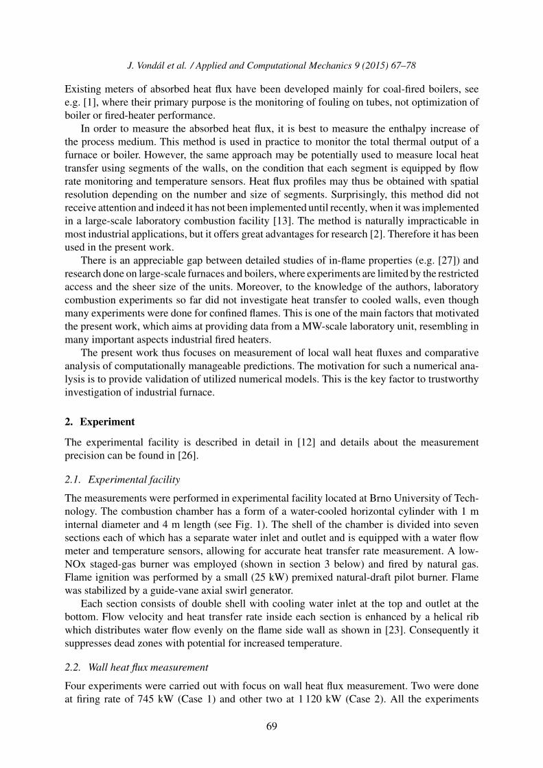
The measurements were performed in experimental facility located at Brno University of Tech-nology. The combustion chamber has a form of a water-cooled horizontal cylinder with 1 minternal diameter and 4 m length (see Fig. 1). The shell of the chamber is divided into sevensections each of which has a separate water inlet and outlet and is equipped with a water flowmeter and temperature sensors, allowing for accurate heat transfer rate measurement. A low-NOx staged-gas burner was employed (shown in section 3 below) and fired by natural gas.Flame ignition was performed by a small (25 kW) premixed natural-draft pilot burner. Flamewas stabilized by a guide-vane axial swirl generator.
Each section consists of double shell with cooling water inlet at the top and outlet at thebottom. Flow velocity and heat transfer rate inside each section is enhanced by a helical ribwhich distributes water flow evenly on the flame side wall as shown in [23]. Consequently itsuppresses dead zones with potential for increased temperature.
2.2. Wall heat flux measurement
Four experiments were carried out with focus on wall heat flux measurement. Two were doneat firing rate of 745 kW (Case 1) and other two at 1 120 kW (Case 2). All the experiments
69
J. Vondal et al. / Applied and Computational Mechanics 9 (2015) 67–78
Fig. 1. Combustion facility with data acquisition system
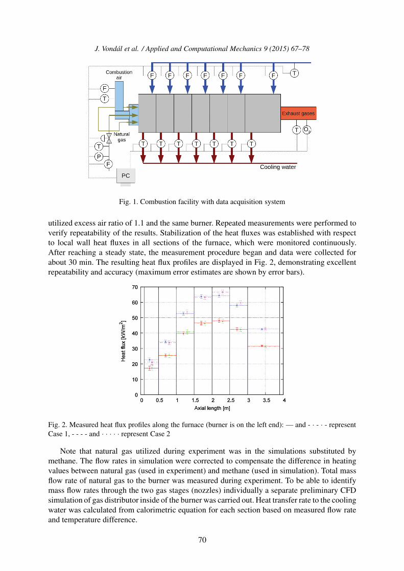
utilized excess air ratio of 1.1 and the same burner. Repeated measurements were performed toverify repeatability of the results. Stabilization of the heat fluxes was established with respectto local wall heat fluxes in all sections of the furnace, which were monitored continuously.After reaching a steady state, the measurement procedure began and data were collected forabout 30 min. The resulting heat flux profiles are displayed in Fig. 2, demonstrating excellentrepeatability and accuracy (maximum error estimates are shown by error bars).
Fig. 2. Measured heat flux profiles along the furnace (burner is on the left end): — and - · - · - representCase 1, - - - - and · · · · · represent Case 2
Note that natural gas utilized during experiment was in the simulations substituted bymethane. The flow rates in simulation were corrected to compensate the difference in heatingvalues between natural gas (used in experiment) and methane (used in simulation). Total massflow rate of natural gas to the burner was measured during experiment. To be able to identifymass flow rates through the two gas stages (nozzles) individually a separate preliminary CFDsimulation of gas distributor inside of the burner was carried out. Heat transfer rate to the coolingwater was calculated from calorimetric equation for each section based on measured flow rateand temperature difference.
70
J. Vondal et al. / Applied and Computational Mechanics 9 (2015) 67–78
3. Modelling
For each of the two cases several combustion simulations were performed. The problem wascarefully set up taking into account recent results of a related investigation [24]. Thermal boun-dary condition on the water-cooled walls was treated by prescribed temperature of 80 ◦C (waterside of inner steel shell) based on previous work published in [23], while adiabatic conditionwas used for all the remaining walls, which are in reality covered by fibrous aluminosilicatethermal insulation. For swirl generation, this work adopts a common practice used in enginee-ring computations, which means that air supply duct is included into the computational domainalong with all important features, including the swirler.
3.1. Flow domain and computational grid
The geometry of the modelled flow domain includes several meters of air supply duct, theburner, and combustion chamber. It was necessary to include the air duct as air enters the burnerfrom a side and the burner does not incorporate any measures (e.g. honeycomb) that wouldhomogenize the flow. In preliminary cold-flow computations it was confirmed that due to thisinlet asymmetry air flow in the burner is far from axially symmetrical.
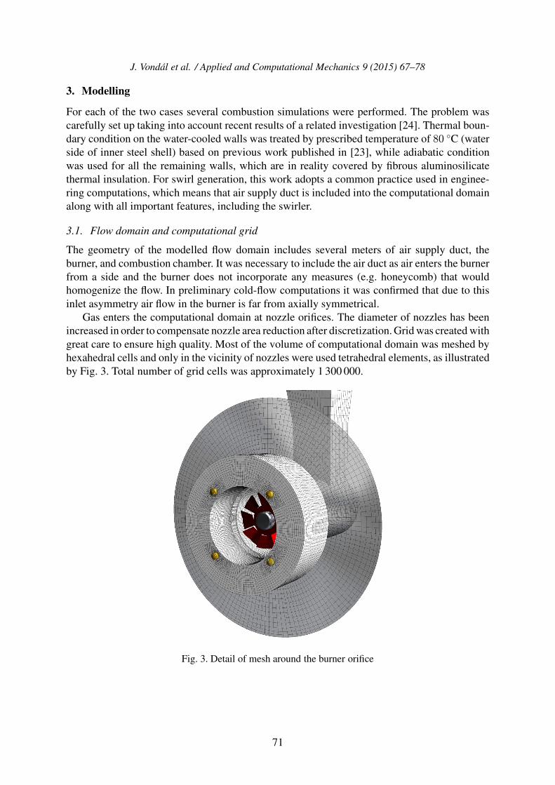
Gas enters the computational domain at nozzle orifices. The diameter of nozzles has beenincreased in order to compensate nozzle area reduction after discretization. Grid was created withgreat care to ensure high quality. Most of the volume of computational domain was meshed byhexahedral cells and only in the vicinity of nozzles were used tetrahedral elements, as illustratedby Fig. 3. Total number of grid cells was approximately 1 300 000.
Fig. 3. Detail of mesh around the burner orifice
71
J. Vondal et al. / Applied and Computational Mechanics 9 (2015) 67–78
3.2. Computational model setup
The objective of this work is to validate the performance of a CFD model that has acceptablecomputational requirements and thus can be applied in the industrial practice. Therefore anindustry-standard two-equation turbulence model was applied, namely k-ε realizable model.Simulations were run in unsteady mode since combustion in this complex geometry displayslarge-scale transient fluctuations (due to precessing flame vortex). To account for turbulence-chemistry interactions and combustion, eddy-dissipation model [14] has been employed. Thismodel falls into the family of eddy breakup models and therefore combustion occurs as soon asfuel and oxidants are mixed by turbulence. Due to this simplifying assumption of the chemistrymodel, single-step reaction mechanism was appropriate.
Solver settings were kept the same for all of the test cases as specified in Tables 1 and 2.Time step was set to 2 ms in order to allow the solver to perform from ten to twenty iterationsper time step before reaching convergence. Instantaneous data were averaged over more than2 s of simulated physical time to calculate time-averaged results.
Table 1. Solver settings of all cases
Model SettingsTurbulence model realizable (or RNG) k-ε or SST k-ω or RSMRadiation model Discrete ordinatesSpecies transport EDM with global one step mechanismPressure-velocity coupling SIMPLECSkewness correction 1Time step [s] 0.002
Table 2. Discretization methods used in all simulations
Variable SchemePressure PRESTO!Density QUICKMomentum QUICKTurbulent Kinetic Energy First Order UpwindSpecific Dissipation Rate First Order UpwindCH4 First Order UpwindO2 First Order UpwindCO2 First Order UpwindH2O First Order UpwindEnergy First Order UpwindDiscrete Ordinates First Order Upwind
3.3. Radiative heat transfer modelling
Compromise in accuracy of modelling of absorption coefficient between simplified grey gasmodel and narrow band models is traditionally represented by the weighted-sum-of-grey-gasesmodel (WSGGM), with coefficients that were first published in [19]. The WSGGM approach issuitable for overall heat transfer predictions in furnaces as noted by [17]. Detailed comparisonof WSGG model to the correlated k-distribution model (CK) and wide band correlated k-distribution (WBCK) model was published by [20]. It shows that WBCK model is significantly
72
J. Vondal et al. / Applied and Computational Mechanics 9 (2015) 67–78
more accurate over WSGG and is not as CPU intensive as CK. Overall error due to WSGG mayreach up to 30 % [4]. However, that work utilized WSGG model with the cell-based mean beamlength, which may be responsible for a great part of the observed deviation, as shown below.
Significant difference between cell-based and domain-based WSGG was observed by [20].The term cell- and domain-based describes the way how the mean beam length is determined.The author shows that cell-based WSGG significantly over-predicts both the total wall heatfluxes and radiative source term when compared to domain-based WSGG and non-grey wideband correlated-k method (WBCK).
In the present computations was applied a new set of parameters for WSGGM, adoptedfrom [28]. Contrary to the standard WSGGM, the new coefficients are suitable even for oxy-fuel combustion. The authors show that their model predicts wall heat fluxes more accurately;the validation was made with experimentally obtained in-flame temperature. In the cell-basedmethod, a characteristic beam length is calculated for each cell. This procedure is straightforwardand well suited to unstructured grids. On the other hand the domain-based procedure is meshindependent, but requires the characterization of domain size by a single value. The procedurefrom [28] defines the domain size parameter as L = Vdomain/Adomain, where L is mean beamlength, Vdomain is volume of the computational domain and Adomain is the surface area of thedomain. In the present analysis, the mean beam length was equal to 3.6 m.
4. Results and discussion
The results of combustion experiment are discussed first to emphasize the properties of themeasured data. Predictions are then discussed from various aspects on the basis of the hardevidence provided by the measured data.
4.1. Discussion of measured data
It is important to note that the present measurements constitute a significant technical challengebecause of the size and complexity of the combustion facility. In such large-scale furnace(roughly 1 MW flames) it is much more difficult to ensure repeatability of all boundary conditionsand thus also of the measured values than in small-scale laboratory experiments (typically lessthan 150 kW). This challenge has however been tackled quite successfully, as proven by therepeatability shown in Fig. 2. In repeated experiments, values of the global heat flux differedby less than 1 % and repeatability of the local heat fluxes was within 3 %. The source of theexisting small differences was related mostly to the uncertainty in measuring air flow rate (about10 %) and much less to the uncertainty of heat flux measurement (on average about 3 %). Thoseuncertainties of local wall heat fluxes are plotted in Figs. 2, 4, 5 and 6 as error bars. Furthermore,the heat balance of the furnace has been closed within 1 % margin of unaccounted heat losses.Accuracy of the measurement has been improved by decreasing flow rate of the cooling water,yet keeping it sufficiently high to prevent boiling, as follows from error propagation analysisthat was done in [25].
Along with good accuracy, the present segmental measurement of heat flux provides severaladvantages. Firstly it is the inherent averaging of heat flux over each of the segments and tosome extent also over the measurement time period. The measured value of local heat flux ineach segment of the furnace is in fact spatial average over each individual segment. It is alsoa floating average in time thanks to heat capacity of the steel shell and cooling water. Positiveeffect of the spatial and temporal averaging is that it eliminates the influence of numeroussources of error and irregularities (including non-symmetry of the flame, flux non-uniformity
73
J. Vondal et al. / Applied and Computational Mechanics 9 (2015) 67–78
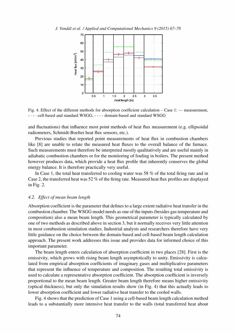
Fig. 4. Effect of the different methods for absorption coefficient calculation – Case 1: — measurement,- · - · cell-based and standard WSGG, - - - - domain-based and standard WSGG
and fluctuations) that influence most point methods of heat flux measurement (e.g. ellipsoidalradiometers, Schmidt-Boelter heat flux sensors, etc.).
Previous studies that reported point measurements of heat flux in combustion chamberslike [8] are unable to relate the measured heat fluxes to the overall balance of the furnace.Such measurements must therefore be interpreted mostly qualitatively and are useful mainly inadiabatic combustion chambers or for the monitoring of fouling in boilers. The present methodhowever produces data, which provide a heat flux profile that inherently conserves the globalenergy balance. It is therefore practically very useful.
In Case 1, the total heat transferred to cooling water was 58 % of the total firing rate and inCase 2, the transferred heat was 52 % of the firing rate. Measured heat flux profiles are displayedin Fig. 2.
4.2. Effect of mean beam length
Absorption coefficient is the parameter that defines to a large extent radiative heat transfer in thecombustion chamber. The WSGG model needs as one of the inputs (besides gas temperature andcomposition) also a mean beam length. This geometrical parameter is typically calculated byone of two methods as described above in section 3, but it normally receives very little attentionin most combustion simulation studies. Industrial analysts and researchers therefore have verylittle guidance on the choice between the domain-based and cell-based beam length calculationapproach. The present work addresses this issue and provides data for informed choice of thisimportant parameter.
The beam length enters calculation of absorption coefficient in two places [28]. First is theemissivity, which grows with rising beam length asymptotically to unity. Emissivity is calcu-lated from empirical absorption coefficients of imaginary gases and multiplicative parametersthat represent the influence of temperature and composition. The resulting total emissivity isused to calculate a representative absorption coefficient. The absorption coefficient is inverselyproportional to the mean beam length. Greater beam length therefore means higher emissivity(optical thickness), but only the simulation results show (in Fig. 4) that this actually leads tolower absorption coefficient and lower radiative heat transfer to the cooled walls.
Fig. 4 shows that the prediction of Case 1 using a cell-based beam length calculation methodleads to a substantially more intensive heat transfer to the walls (total transferred heat about
74
J. Vondal et al. / Applied and Computational Mechanics 9 (2015) 67–78
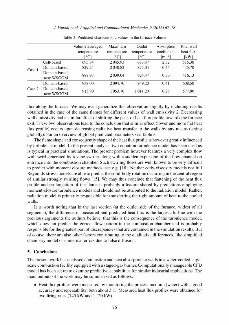
17.6 % above the measured total heat flux). To explain this behaviour, we can look at the averagevalue of absorption coefficient (volume averaging over the entire combustion chamber). Theaverage value of absorption coefficient is almost an order of magnitude higher for the cell-basedbeam length approach than for the domain-based approach (about 2.3 and 0.4, respectively).High absorption coefficient in the cell-based approach makes the flame more luminous and thisenhances heat transfer to the walls.
It is therefore clear that the present work leads to a recommendation to use a domain-basedbeam length calculation method, which predicts total heat transfer to the walls 1.7 % and 2.4 %above the measured values for Case 1 and 2, respectively. In both cases the total heat transfer tocooled walls is slightly over-predicted. Local heat transfer rates in individual segments displaylarger deviations, generally the predicted profiles are flatter and peak loads are shifted slightlyfarther from the burner.
4.3. Effect of WSGGM coefficients
In order to further analyse the effect of the gas radiative properties, standard WSGG methodthat uses empirical coefficients published by [19] has been substituted in simulation of the twoCases 1 and 2 by a newer set of coefficients published by [28]. The work of [28] comparedWSGG predictions with a significantly more accurate spectral method (exponential wide bandmodel), but employed the cell-based beam length and did not offer any validation by measuredheat fluxes.
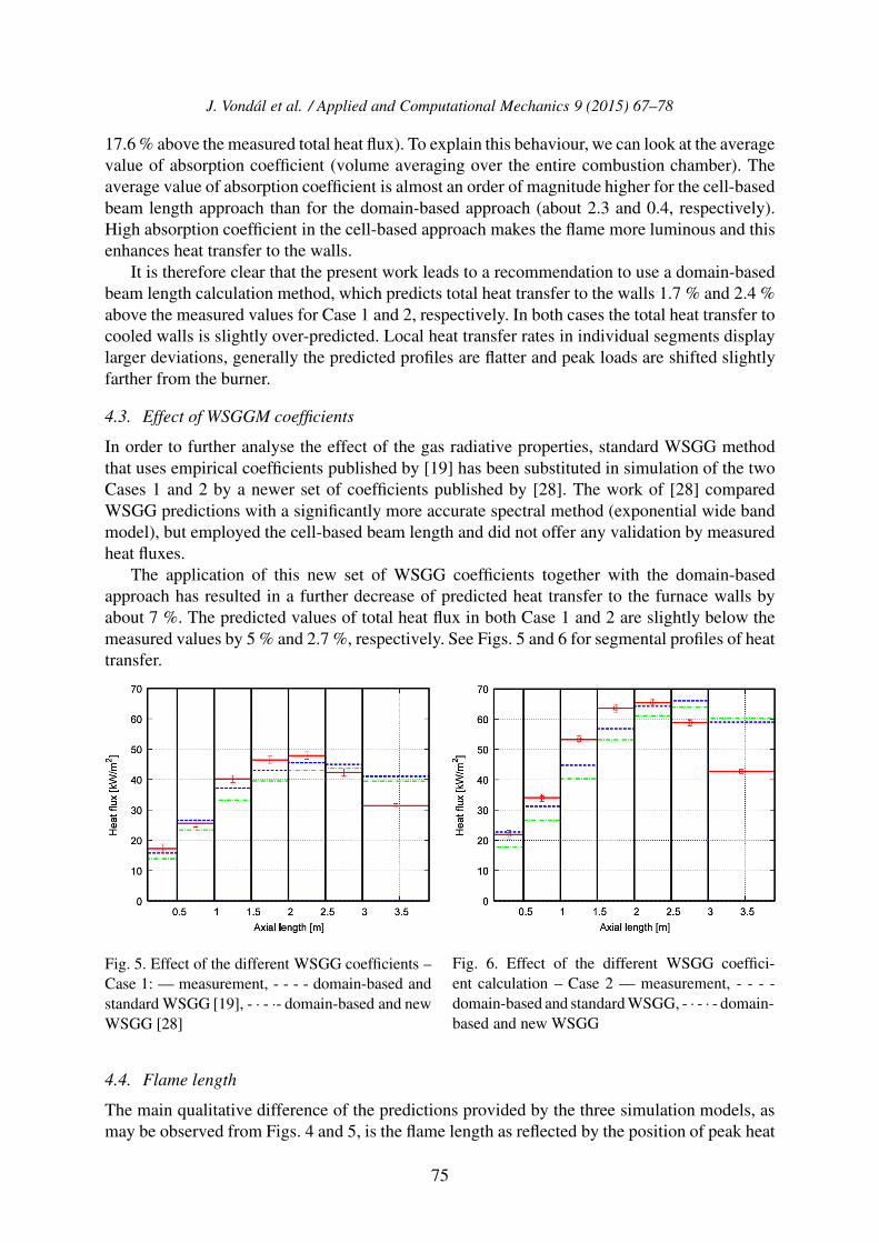
The application of this new set of WSGG coefficients together with the domain-basedapproach has resulted in a further decrease of predicted heat transfer to the furnace walls byabout 7 %. The predicted values of total heat flux in both Case 1 and 2 are slightly below themeasured values by 5 % and 2.7 %, respectively. See Figs. 5 and 6 for segmental profiles of heattransfer.
Fig. 5. Effect of the different WSGG coefficients –Case 1: — measurement, - - - - domain-based andstandard WSGG [19], - · - ·- domain-based and newWSGG [28]
Fig. 6. Effect of the different WSGG coeffici-ent calculation – Case 2 — measurement, - - - -domain-based and standard WSGG, - · - · - domain-based and new WSGG
4.4. Flame length
The main qualitative difference of the predictions provided by the three simulation models, asmay be observed from Figs. 4 and 5, is the flame length as reflected by the position of peak heat
75
J. Vondal et al. / Applied and Computational Mechanics 9 (2015) 67–78
Table 3. Predicted characteristic values in the furnace volume
Case 2Domain-based 938.00 2 094.70 949.20 0.41 608.50Domain-based,new WSGGM
915.90 1 953.70 1 011.20 0.29 577.90
flux along the furnace. We may even generalize this observation slightly by including resultsobtained in the case of the same flames for different values of wall emissivity 2. Decreasingwall emissivity had a similar effect of shifting the peak of heat flux profile towards the furnaceexit. These two observations lead to the conclusion that similar effect (lower and more flat heatflux profile) occurs upon decreasing radiative heat transfer to the walls by any means (actingglobally). For an overview of global predicted parameters see Table 3.
The flame shape and consequently shape of the heat flux profile is however greatly influencedby turbulence model. In the present analysis, two-equation turbulence model has been used asis typical in practical simulations. The present problem however features a very complex flowwith swirl generated by a vane swirler along with a sudden expansion of the flow channel onentrance into the combustion chamber. Such swirling flows are well known to be very difficultto predict with moment closure methods, see e.g. [18]. Neither eddy-viscosity models nor fullReynolds-stress models are able to predict the solid-body rotation occurring in the central regionof similar strongly swirling flows [15]. We may thus conclude that flattening of the heat fluxprofile and prolongation of the flame is probably a feature shared by predictions employingmoment-closure turbulence models and should not be attributed to the radiation model. Rather,radiation model is primarily responsible for transferring the right amount of heat to the cooledwalls.
It is worth noting that in the last section (at the outlet side of the furnace, widest of allsegments), the difference of measured and predicted heat flux is the largest. In line with theprevious arguments the authors believe, that this is the consequence of the turbulence model,which does not predict the correct flow pattern in the combustion chamber and is probablyresponsible for the greatest part of discrepancies that are contained in the simulation results. Butof course, there are also other factors contributing to the qualitative differences, like simplifiedchemistry model or numerical errors due to false diffusion.
5. Conclusions
The present work has analysed combustion and heat absorption to walls in a water-cooled large-scale combustion facility equipped with a staged-gas burner. Computationally manageable CFDmodel has been set up to examine predictive capabilities for similar industrial applications. Themain outputs of the work may be summarized as follows:
• Heat flux profiles were measured by monitoring the process medium (water) with a goodaccuracy and repeatability, both about 3 %. Measured heat flux profiles were obtained fortwo firing rates (745 kW and 1 120 kW).
76
J. Vondal et al. / Applied and Computational Mechanics 9 (2015) 67–78
• A computationally manageable model has been shown to yield satisfactory overall heattransfer rate predictions.
• Method of computing mean beam length has been shown to have a major impact on theoverall heat transfer rate. The domain-based method has been shown to give superiorresults when compared to the cell-based method.
• New set of WSGGM coefficients adopted from [28] has been validated. It led to slightunder-prediction of the total measured heat transfer rate (by 3 and 5 %), decreasing totalheat transfer by about 7 % as compared to standard WSGGM coefficients from [19]. Thestandard WSGGM coefficients yielded slightly more accurate overall heat transfer rates(over-prediction by about 2 %).
• Flame length was slightly over-predicted in all of the simulations and predicted heatflux profiles were flatter than the measured, which has been attributed to modellingsimplifications.
Acknowledgements
The research leading to these results has received funding from the Ministry of Education, Youthand Sports under the National Sustainability Programme I (Project LO1202). This work wasalso supported by the project CZ.1.07/2.3.00/30.0039 of Brno University of Technology.
Reference
[1] Beckmann, M., Kruger, S., Spiegel, W., A method for non-invasive heat flux detection in membranewalls of steam generators, Proceedings of the Annual International Conference on Incinerationand Thermal Treatment Technologies, Savannah, USA, Air and Waste Management Association,2006, pp. 531–550.
[2] Belohradsky, P., Skryja, P., Hudak, I. Experimental study on the influence of oxygen content in thecombustion air on the combustion characteristics, Energy 75 (2014) 116–126.
[3] Butler, B. W., Denison, M. K., Webb, B. W., Radiation heat transfer in a laboratory-scale, pulverizedcoal-fired reactor, Experimental Thermal and Fluid Science, 9 (1) (1994) 69–79.
[4] Coelho, P. J., Numerical simulation of radiative heat transfer from non-gray gases in three-dimensional enclosures, Journal of Quantitative Spectroscopy and Radiative Transfer 74 (3) (2002)307–328.
[5] Frassoldati, A., Frigerio, S., Colombo, E., Inzoli, F., Faravelli, T., Determination of NOx emis-sions from strong swirling confined flames with an integrated CFD-based procedure, ChemicalEngineering Science 60 (11) (2005) 2 851–2 869.
[6] Fureby, C., LES of a ulti-burner annular gas turbine combustor, Flow, Turbulence and Combustion84 (3) (2010) 543–564.
[7] Fureby, C., Grinstein, F. F., Li, G., Gutmark, E. J., An experimental and computational studyof a multi-swirl gas turbine combustor, Proceedings of the Combustion Institute 31 (2) (2007)3 107–3 114.
[8] Hayes, R. R., Brewster, S., Webb, B. W., McQuay, M. Q., Huber, A. M., Crown incident radiantheat flux measurements in an industrial, regenerative, gas-fired, flat-glass furnace, ExperimentalThermal and Fluid Science 24 (1–2) (2001) 35–46.
[9] Hu, G., Wang, H., Qian, F., Van Geem, K. M., Schietekat, C. M., Marin, G. B., Coupled simu-lation of an industrial naphtha cracking furnace equipped with long-flame and radiation burners,Computers & Chemical Engineering 38 (2012) 24–34.
77
J. Vondal et al. / Applied and Computational Mechanics 9 (2015) 67–78
[10] Jaluria, Y., Challenges in the accurate numerical simulation of practical thermal processes andsystems, International Journal of Numerical Methods for Heat and Fluid Flow 23 (1) (2013)158–175.
[11] James, S., Zhu, J., Anand, M. S., Large eddy simulations of turbulent flames using the filtereddensity function model, Proceedings of the Combustion Institute 31 (2) (2007) 1 737–1 745.
[12] Kermes, V., Belohradsky, P., Biodiesel (EN 14213) heating oil substitution potential for petroleumbased light heating oil in a 1 MW stationary combustion facility, Biomass and Bioenergy 49 (2013)10–21.
[13] Kermes, V., Belohradsky, P., Oral, J., Stehlık, P., Testing of gas and liquid fuel burners for powerand process industries, Energy 33 (10) (2008) 1 551–1 561.
[14] Magnussen, B. F., Hjertager, B. H., On mathematical modeling of turbulent combustion withspecial emphasis on soot formation and combustion, Symposium (International) on Combustion16 (1) (1977) 719–729.
[15] Mitrofanova, O. V., Hydrodynamics and heat transfer in swirling flows in channels with swirlers(analytical review), High Temperature 41 (4) (2003) 518–559.
[16] Paist, A., Poobus, A., Tiikma, T., Probes for measuring heat transfer parameters and foulingintensity in boilers, Fuel 81 (14) (2002) 1 811–1 818.
[17] Saario, A., Oksanen, A., Effect of computational grid in industrial-scale boiler modeling, Inter-national Journal of Numerical Methods for Heat & Fluid Flow 19 (1) (2009) 93–117.
[18] Sadiki, A., Maltsev, A., Wegner, B., Flemming, F., Kempf, A., Janicka, J., Unsteady methods(URANS and LES) for simulation of combustion systems, International Journal of ThermalSciences 45 (8) (2006) 760–773.
[19] Smith, T. F., Shen, Z. F., Friedman, J. N., Evaluation of coefficients for the weighted sum of graygases model, Journal of Heat Transfer 104 (4) (1982) 602–608.
[20] Strohle, J., Spectral modelling of radiative heat transfer in industrial furnaces, PhD Thesis, Uni-versity of Stuttgart, Shaker Verlag GmbH, Aachen, 2004.
[21] Taler, J., Duda, P., Weglowski, B., Zima, W., Gradziel, S., Sobota, T., Taler, D., Identification oflocal heat flux to membrane water-walls in steam boilers, Fuel 88 (2) (2009) 305–311.
[22] Vondal, J., Computational modeling of turbulent swirling diffusion flames, PhD Thesis, BrnoUniversity of Technology, 2012.
[23] Vondal, J., Hajek, J., Boundary condition evaluation and stability issues in swirling flame gascombustion, Proceedings of the conference ThermaComp2009, Naples, Italy, 2009, pp. 314–317.
[24] Vondal, J., Hajek, J., Experimental and numerical investigation of swirling non-premixed gasflames in industrial-scale furnace, Proceedings of the 9th European Conference on IndustrialFurnaces and Boilers, Estoril, 2011.
[25] Vondal, J., Hajek, J., Experimental data of the local wall heat flux for combustion codes validationin non-premixed swirling gas flames, Proceedings of the ASME-ATI-UIT 2010 Conference onThermal and Environmental Issues in Energy Systems, Sorrento, 2010, pp. 931–936.
[26] Vondal, J., Hajek, J., Kermes, V. Local wall heat fluxes in swirling non-premixed natural gasflames in large-scale combustor: Data for validation of combustion codes, Chemical EngineeringTransactions 21 (2) (2010) 1 123–1 128.
[27] Xiouris, C. Z., Koutmos, P., Fluid dynamics modeling of a stratified disk burner in swirl co-flow,Applied Thermal Engineering 35 (2012) 60–70.
[28] Yin, C., Johansen, L. C. R., Rosendahl, L. A., Kær, S. K., New weighted sum of gray gasesmodel applicable to Computational Fluid Dynamics (CFD) modeling of oxy-Fuel combustion:Derivation, validation, and implementation, Energy & Fuels 24 (12) (2010) 6 275–6 282.