UK/IE INSTRUCTION MANUAL INSTALLATION, COMMISSIONING & SERVICING WALL HUNG RSF GAS FIRED CONDENSING BOILER FOR OPEN VENTED AND SEALED CENTRAL HEATING SYSTEMS AND INDIRECT MAINS FED DOMESTIC HOT WATER THIS BOILER IS USED WITH NATURAL GAS OR LPG (Cat II 2H3P TYPE C13, C33 & C53) NATURAL GAS 12 Ri GC NUMBER: 41 311 63 15 Ri GC NUMBER: 41 311 75 18 Ri GC NUMBER: 41 311 77 24 Ri GC NUMBER: 41 311 65 LIQUID PETROLEUM GAS 12 Ri GC NUMBER: 41 311 64 15 Ri GC NUMBER: 41 311 76 18 Ri GC NUMBER: 41 311 78 24 Ri GC NUMBER: 41 311 66 GREENSTAR 12Ri, 15Ri, 18Ri & 24Ri
FOR OPEN VENTED AND SEALED CENTRAL HEATING SYSTEMS AND
INDIRECT MAINS FED DOMESTIC HOT WATER
THIS BOILER IS USED WITHNATURAL GAS OR LPG (Cat II 2H3P TYPE C13, C33 & C53)
NATURAL GAS 12 Ri GC NUMBER: 41 311 63
15 Ri GC NUMBER: 41 311 75
18 Ri GC NUMBER: 41 311 77
24 Ri GC NUMBER: 41 311 65
LIQUID PETROLEUM GAS 12 Ri GC NUMBER: 41 311 64
15 Ri GC NUMBER: 41 311 7618 Ri GC NUMBER: 41 311 7824 Ri GC NUMBER: 41 311 66
GREENSTAR 12Ri, 15Ri, 18Ri & 24Ri
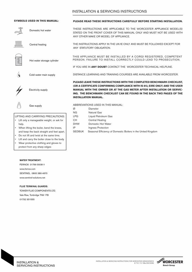
SYMBOLS USED IN THIS MANUAL:
Central heating
Domestic hot water
Cold water main supply
Electricity supply
Gas supply
Hot water storage cylinder
PLEASE READ THESE INSTRUCTIONS CAREFULLY BEFORE STARTING INSTALLATION.
THESE INSTRUCTIONS ARE APPLICABLE TO THE WORCESTER APPLIANCE MODEL(S)STATED ON THE FRONT COVER OF THIS MANUAL ONLY AND MUST NOT BE USED WITHANY OTHER MAKE OR MODEL OF APPLIANCE.
THE INSTRUCTIONS APPLY IN THE UK/IE ONLY AND MUST BE FOLLOWED EXCEPT FOR ANY STATUTORY OBLIGATION.
THIS APPLIANCE MUST BE INSTALLED BY A CORGI REGISTERED, COMPETENT PERSON. FAILURE TO INSTALL CORRECTLY COULD LEAD TO PROSECUTION.
IF YOU ARE IN ANY DOUBT CONTACT THE WORCESTER TECHNICAL HELPLINE.
DISTANCE LEARNING AND TRAINING COURSES ARE AVAILABLE FROM WORCESTER.
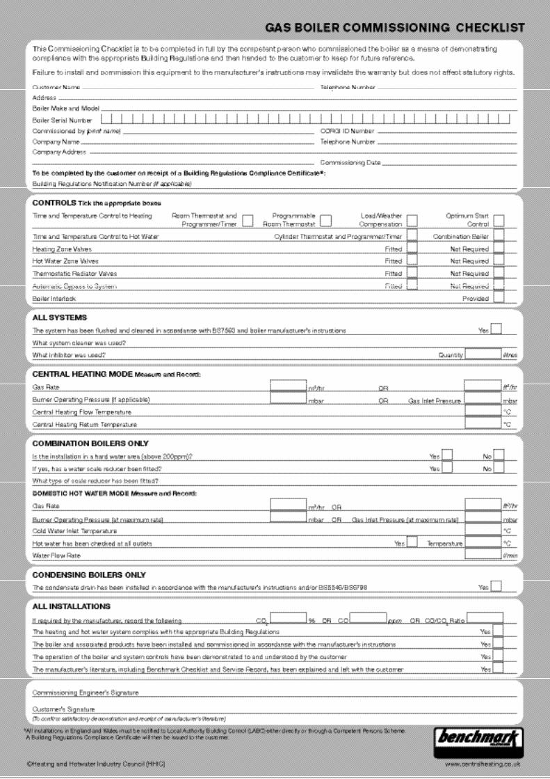
PLEASE LEAVE THESE INSTRUCTIONS WITH THE COMPLETED BENCHMARK CHECKLIST,(OR A CERTIFICATE CONFIRMING COMPLIANCE WITH IS 813, EIRE ONLY) AND THE USERMANUAL WITH THE OWNER OR AT THE GAS METER AFTER INSTALLATION OR SERVIC-ING. THE BENCHMARK CHECKLIST CAN BE FOUND IN THE BACK TWO PAGES OF THEINSTALLATION MANUAL.
ABBREVIATIONS USED IN THIS MANUAL:Ø DiameterNG Natural GasLPG Liquid Petroleum GasCH Central HeatingDHW Domestic Hot WaterIP Ingress ProtectionSEDBUK Seasonal Efficiency of Domestic Boilers in the United Kingdom
INSTALLATION & SERVICING INSTRUCTIONS
LIFTING AND CARRYING PRECAUTIONS:• Lift only a manageable weight, or ask for
help. • When lifting the boiler, bend the knees,
and keep the back straight and feet apart. • Do not lift and twist at the same time. • Lift and carry the boiler close to the body• Wear protective clothing and gloves to
A Benchmark Checklist is provided by Worcester, Bosch Group, at the back of this manual, for the installer to complete. The checklist will include their CORGI registration number to
confirm that the boiler has been installed, commissioned and serviced according to the manufacturer’s instructions.
IMPORTANT: The completed Benchmark Checklist will be required in the event of anywarranty work and may be required by the local Building Control Inspector.
HEALTH & SAFETY
The appliance contains no asbestos and no substances have been used in theconstruction process that contravene the COSHH Regulations (Control of SubstancesHazardous to Health Regulations 1988).
COMBUSTIBLE AND CORROSIVE MATERIALS
Do not store or use any combustible materials (paper, thinners, paints etc.) inside orwithin the vicinity of the appliance.Chemically aggressive substances, can corrode the appliance and invalidate any
warranty.
FITTING & MODIFICATIONS
Fitting the appliance and any controls to the appliance may only be carried out by acompetent engineer in accordance with the current Gas Safety (Installation and Use)Regulations.Flue systems must not be modified in any way other than as described in the fittinginstructions. Any misuse or unauthorised modifications to the appliance, flue orassociated components and systems will invalidate the warranty. The manufactureraccepts no liability arising from any such actions, excluding statutory rights.
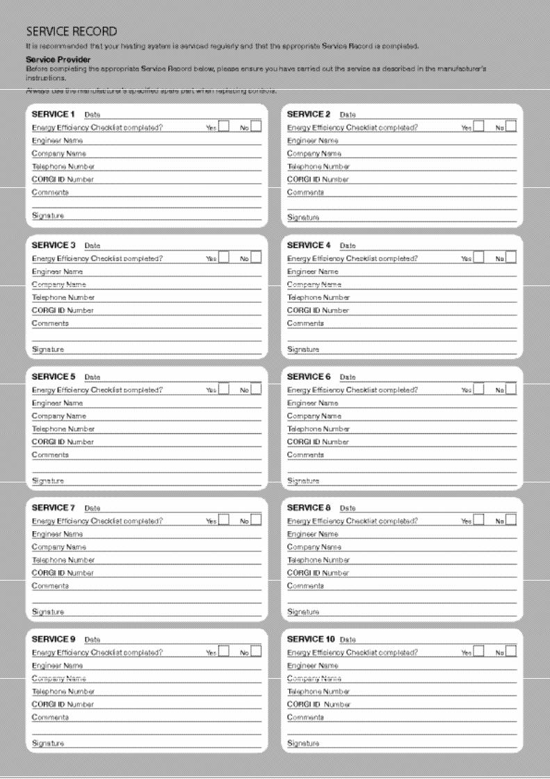
SERVICING
Advise the user to have the system serviced annually by a competent, qualifiedengineer (such as British Gas or other CORGI registered personnel) using approved
to help maintain the economy, safety and reliability of the appliance.IMPORTANT - The service engineer must complete the Service Record on the
Benchmark Checklist after each service.
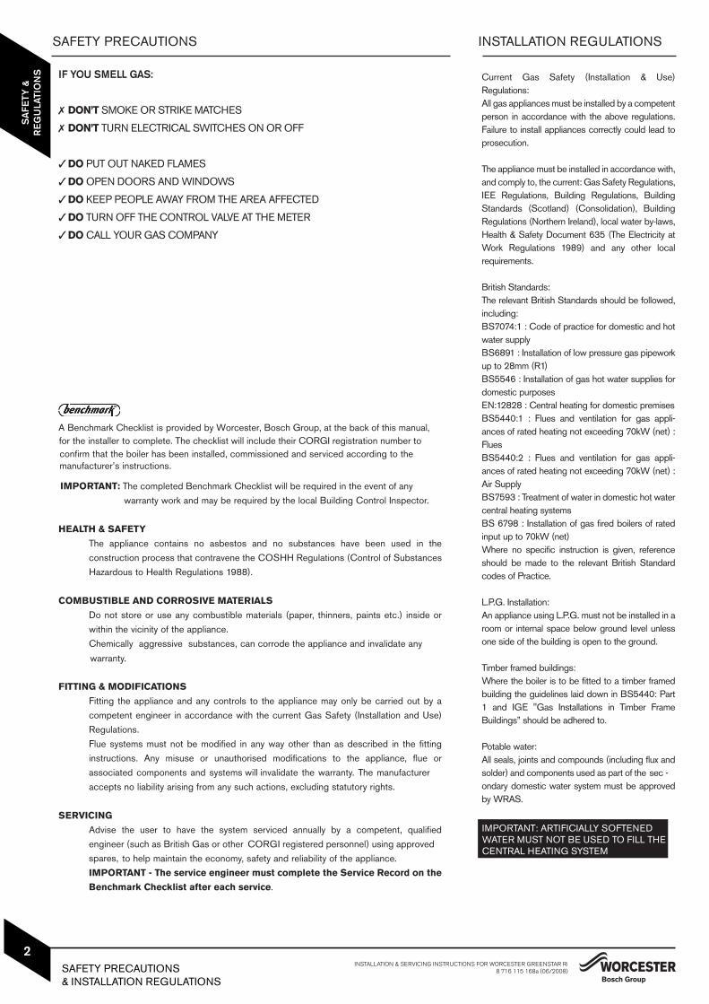
Current Gas Safety (Installation & Use)Regulations: All gas appliances must be installed by a competentperson in accordance with the above regulations.Failure to install appliances correctly could lead toprosecution.
The appliance must be installed in accordance with,and comply to, the current: Gas Safety Regulations,IEE Regulations, Building Regulations, BuildingStandards (Scotland) (Consolidation), BuildingRegulations (Northern Ireland), local water by-laws,Health & Safety Document 635 (The Electricity atWork Regulations 1989) and any other localrequirements.
British Standards:The relevant British Standards should be followed,including:BS7074:1 : Code of practice for domestic and hotwater supplyBS6891 : Installation of low pressure gas pipeworkup to 28mm (R1)BS5546 : Installation of gas hot water supplies fordomestic purposesEN:12828 : Central heating for domestic premisesBS5440:1 : Flues and ventilation for gas appli-ances of rated heating not exceeding 70kW (net) :FluesBS5440:2 : Flues and ventilation for gas appli-ances of rated heating not exceeding 70kW (net) :Air SupplyBS7593 : Treatment of water in domestic hot watercentral heating systemsBS 6798 : Installation of gas fired boilers of ratedinput up to 70kW (net)Where no specific instruction is given, referenceshould be made to the relevant British Standardcodes of Practice.
L.P.G. Installation:An appliance using L.P.G. must not be installed in aroom or internal space below ground level unlessone side of the building is open to the ground.
Timber framed buildings:Where the boiler is to be fitted to a timber framedbuilding the guidelines laid down in BS5440: Part1 and IGE "Gas Installations in Timber FrameBuildings” should be adhered to.
Potable water:All seals, joints and compounds (including flux andsolder) and components used as part of the sec -ondary domestic water system must be approvedby WRAS.
IMPORTANT: ARTIFICIALLY SOFTENED WATER MUST NOT BE USED TO FILL THE CENTRAL HEATING SYSTEM.
CLEANING PRIMARY SYSTEMS INSTALLATION & SERVICING INSTRUCTIONS FOR WORCESTER GREENSTAR Ri8 716 115 168a (06/2008)
6
PR
E -
INS
TALL
ATIO
N
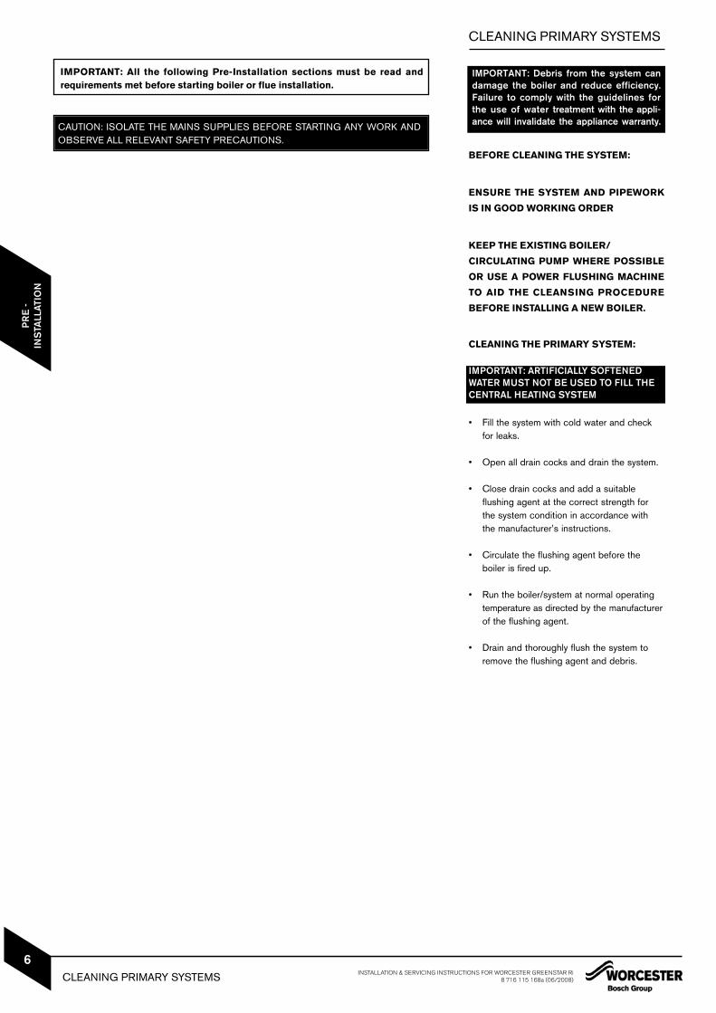
IMPORTANT: Debris from the system candamage the boiler and reduce efficiency.Failure to comply with the guidelines forthe use of water treatment with the appli-ance will invalidate the appliance warranty.
BEFORE CLEANING THE SYSTEM:
ENSURE THE SYSTEM AND PIPEWORK
IS IN GOOD WORKING ORDER
KEEP THE EXISTING BOILER/
CIRCULATING PUMP WHERE POSSIBLE
OR USE A POWER FLUSHING MACHINE
TO AID THE CLEANSING PROCEDURE
BEFORE INSTALLING A NEW BOILER.
CLEANING THE PRIMARY SYSTEM:
IMPORTANT: ARTIFICIALLY SOFTENEDWATER MUST NOT BE USED TO FILL THECENTRAL HEATING SYSTEM
• Fill the system with cold water and check for leaks.
• Open all drain cocks and drain the system.
• Close drain cocks and add a suitableflushing agent at the correct strength for the system condition in accordance with the manufacturer’s instructions.
• Circulate the flushing agent before theboiler is fired up.
• Run the boiler/system at normal operatingtemperature as directed by the manufacturerof the flushing agent.
• Drain and thoroughly flush the system toremove the flushing agent and debris.
IMPORTANT: All the following Pre-Installation sections must be read and requirements met before starting boiler or flue installation.
CAUTION: ISOLATE THE MAINS SUPPLIES BEFORE STARTING ANY WORK ANDOBSERVE ALL RELEVANT SAFETY PRECAUTIONS.
CLEANING PRIMARY SYSTEMS
MAINS SUPPLY
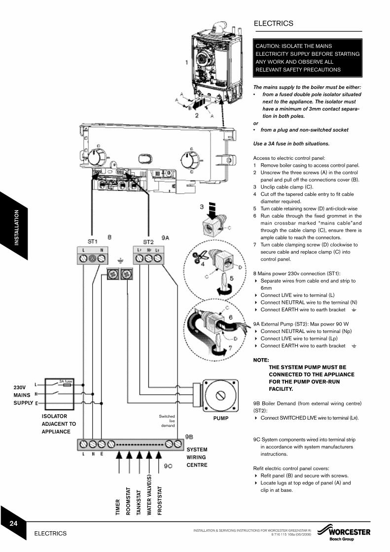
ELECTRIC SUPPLY:• Supply: 230V - 50Hz, 50 watts not including pump.
• Cable: PVC insulated 0.75mm2 (24 x 0.2mm)temperature rated to 90°C.
• External 3A fuse to BS1362.• The appliance must be earthed.• Mains supply to the boiler and system wiring
centre must be through one common fused double pole isolator situated adjacent to the appliance.
• Wiring must comply with IEE wiring regulationsand any local regulations which may apply to fixed wiring to a stationary appliance.
GAS SUPPLY:• Boilers using NG must be connected to a
governed meter.• LPG boilers must be connected to a
regulator.• Installation and connection of the gas supply
to the boiler must be in accordance with BS6891.
• The meter or regulator and pipework to the meter must be checked, preferably by the gas supplier, to ensure it is in good working order and can meet the gas flow and pressure requirements in addition to the demand from any other appliance being served. This does not include the pipework from the meter to the boiler.
GAS SUPPLY PIPE SIZING:
12 & 15 Ri MODELS
Provided that the correct gas supply workingpressure and gas rate can be achieved (see technical data table page 4commissioning section, page 30, also refer to BS 6891)Then it may be possible to reduce the gassupply pipe diameter to 15mm. Generally speaking, the appliance wouldneed to be within 3 to 4 metres of the gasmeter. However, this will depend on the dis-tribution pipe size and route.
This appliance must not be connected to a three phase supply.
•
•
18 & 24 Ri MODELS
Under no circumstances should the size of the gas supply pipe be less than 22mm.
PLASTIC PIPEWORK & UNDER FLOORHEATING:• Any plastic pipework must have a polymeric
barrier with 600mm (minimum) length of copper pipe connected to the boiler.
• Plastic pipework used for underfloor heating must be correctly controlled with a thermostatic blending valve limiting the temperature of the circuits to approx. 50°C.
CONNECTIONS/VALVES:• All system connections, taps and mixing
valves must be capable of sustaining a pressure up to 3 bar.
• Radiator valves should conform to BS2767:10.
• All other valves should conform to BS1010.• On new installations TRV’s must be used on
all radiators except where a room thermostat is sited. On all installations TRV’s should at least be fitted in the sleeping areas. See notebelow on open radiator/bypass
• A drain cock is required at the lowest point on the system.
• An air vent is required at the highest point on the system.
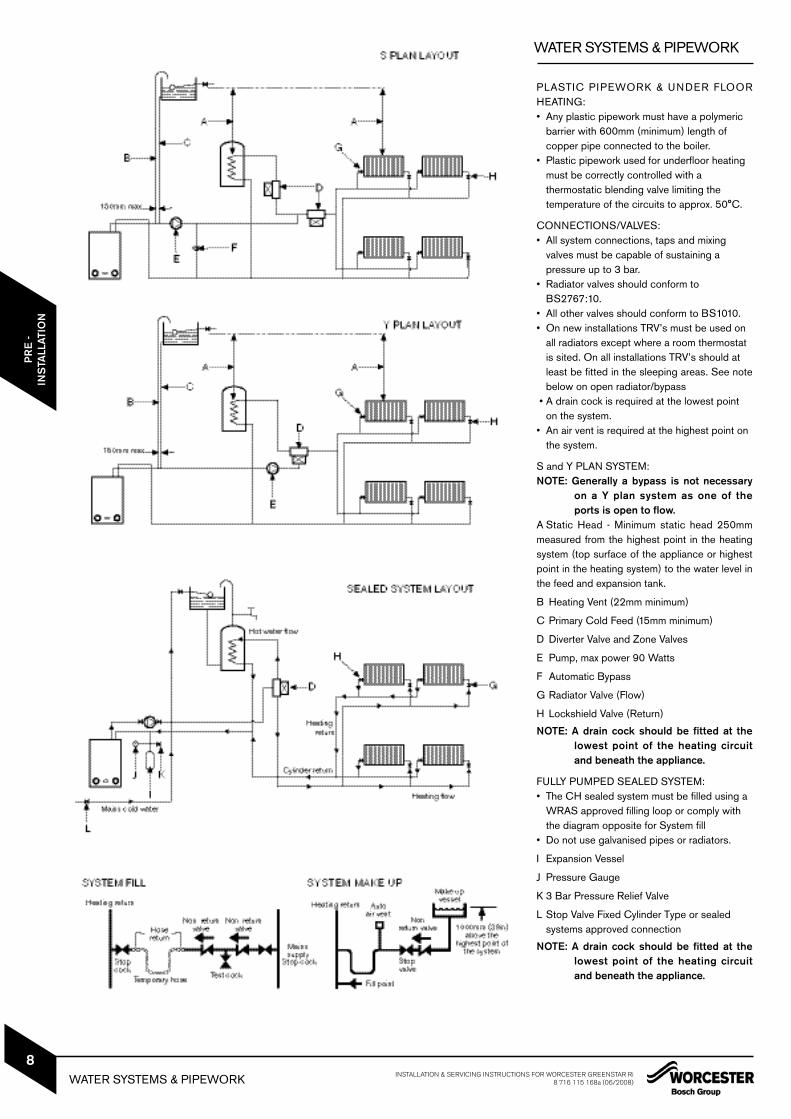
S and Y PLAN SYSTEM:NOTE: Generally a bypass is not necessary
on a Y plan system as one of theports is open to flow.
A Static Head - Minimum static head 250mmmeasured from the highest point in the heatingsystem (top surface of the appliance or highestpoint in the heating system) to the water level inthe feed and expansion tank.
B Heating Vent (22mm minimum)
C Primary Cold Feed (15mm minimum)
D Diverter Valve and Zone Valves
E Pump, max power 90 Watts
F Automatic Bypass
G Radiator Valve (Flow)
H Lockshield Valve (Return)
NOTE: A drain cock should be fitted at thelowest point of the heating circuitand beneath the appliance.
FULLY PUMPED SEALED SYSTEM:• The CH sealed system must be filled using a
WRAS approved filling loop or comply with the diagram opposite for System fill
• Do not use galvanised pipes or radiators.
I Expansion Vessel
J Pressure Gauge
K 3 Bar Pressure Relief Valve
L Stop Valve Fixed Cylinder Type or sealed systems approved connection
NOTE: A drain cock should be fitted at thelowest point of the heating circuitand beneath the appliance.
WATER SYSTEMS & PIPEWORK INSTALLATION & SERVICING INSTRUCTIONS FOR WORCESTER GREENSTAR Ri8 716 115 168a (06/2008)
8
PR
E -
INS
TALL
ATIO
NIN
STA
LLAT
ION
CO
MM
ISS
ION
ING
Soil & vent stack22mmØ
minimum 450mm and up to 3 storeys
Condensing Boiler
Invert
Condensate drainage pipe can be run above or below ground
25mm
Bottom of tube sealed
Limestone chippings Hole depth
400mm min.by 300 Ø
Drainage holes
22mmØ condensate drainage pipe, max external length 3 metres
Diameter 100mmmin. plastic tube
500mm min.
75 mm min.
Condensing Boiler
22mmØ plastic pipe
75mm sink waste trap
Open end of condensate drainage pipe directly into gully below grating but above water level
Visible air break at plug hole
22 mm Ø plastic condensate drainage pipe running through the external wall
External air break
Air gap
External rain water pipe into foul water
68 mm Ø PVC-u strap on fitting
43 mm 90° M & F bend
100mm
Sink with integral overflow
Condensing Boiler
Insulation or increase pipe size
Insulation or increase pipe size
Insulation orincrease pipe size
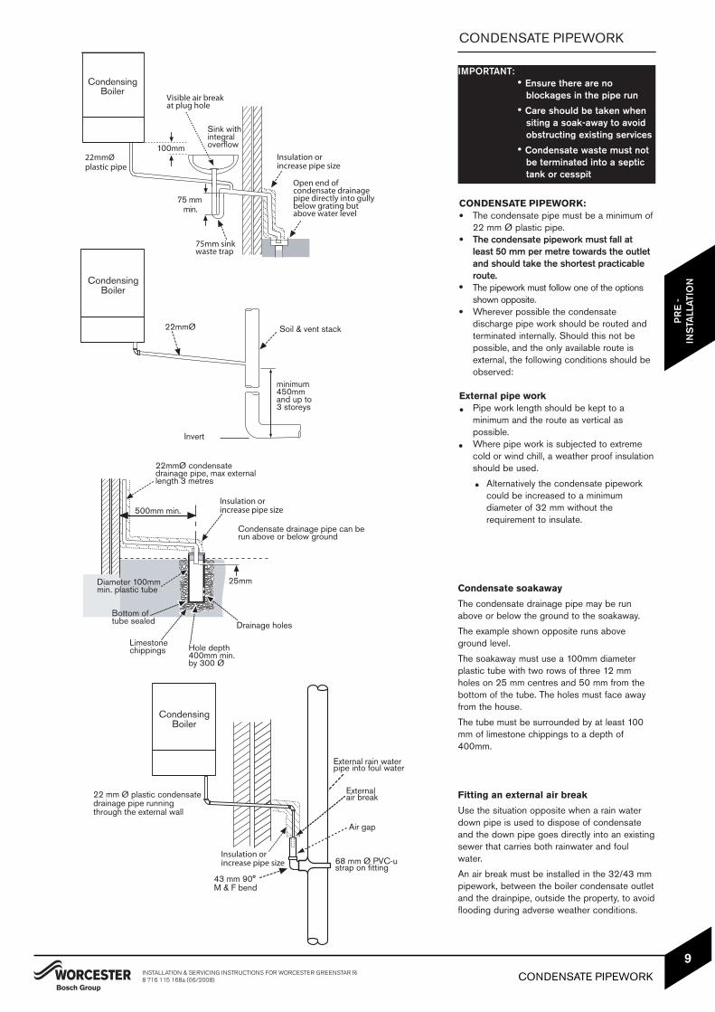
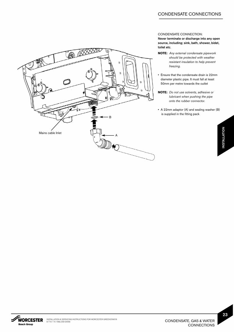
CONDENSATE PIPEWORK
Fitting an external air break
Use the situation opposite when a rain waterdown pipe is used to dispose of condensateand the down pipe goes directly into an existingsewer that carries both rainwater and foulwater.
An air break must be installed in the 32/43 mmpipework, between the boiler condensate outletand the drainpipe, outside the property, to avoidflooding during adverse weather conditions.
CONDENSATE PIPEWORK:The condensate pipe must be a minimum of22 mm Ø plastic pipe.The condensate pipework must fall atleast 50 mm per metre towards the outletand should take the shortest practicableroute.The pipework must follow one of the optionsshown opposite.Wherever possible the condensatedischarge pipe work should be routed andterminated internally. Should this not bepossible, and the only available route isexternal, the following conditions should beobserved:
External pipe workPipe work length should be kept to aminimum and the route as vertical aspossible.Where pipe work is subjected to extremecold or wind chill, a weather proof insulationshould be used.
Alternatively the condensate pipeworkcould be increased to a minimumdiameter of 32 mm without therequirement to insulate.h
IMPORTANT:• Ensure there are no
blockages in the pipe run
• Care should be taken whensiting a soak-away to avoidobstructing existing services
• Condensate waste must notbe terminated into a septictank or cesspit
Condensate soakaway
The condensate drainage pipe may be runabove or below the ground to the soakaway.
The example shown opposite runs aboveground level.
The soakaway must use a 100mm diameterplastic tube with two rows of three 12 mmholes on 25 mm centres and 50 mm from thebottom of the tube. The holes must face awayfrom the house.
The tube must be surrounded by at least 100mm of limestone chippings to a depth of400mm.
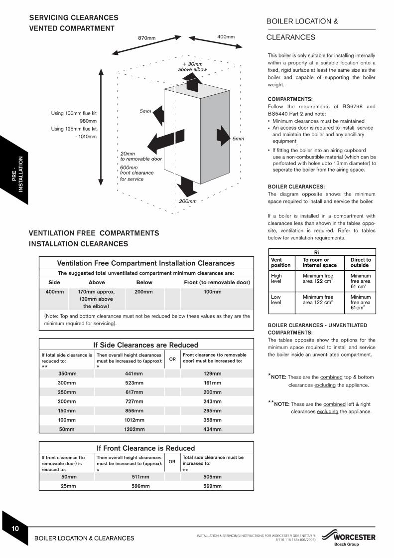
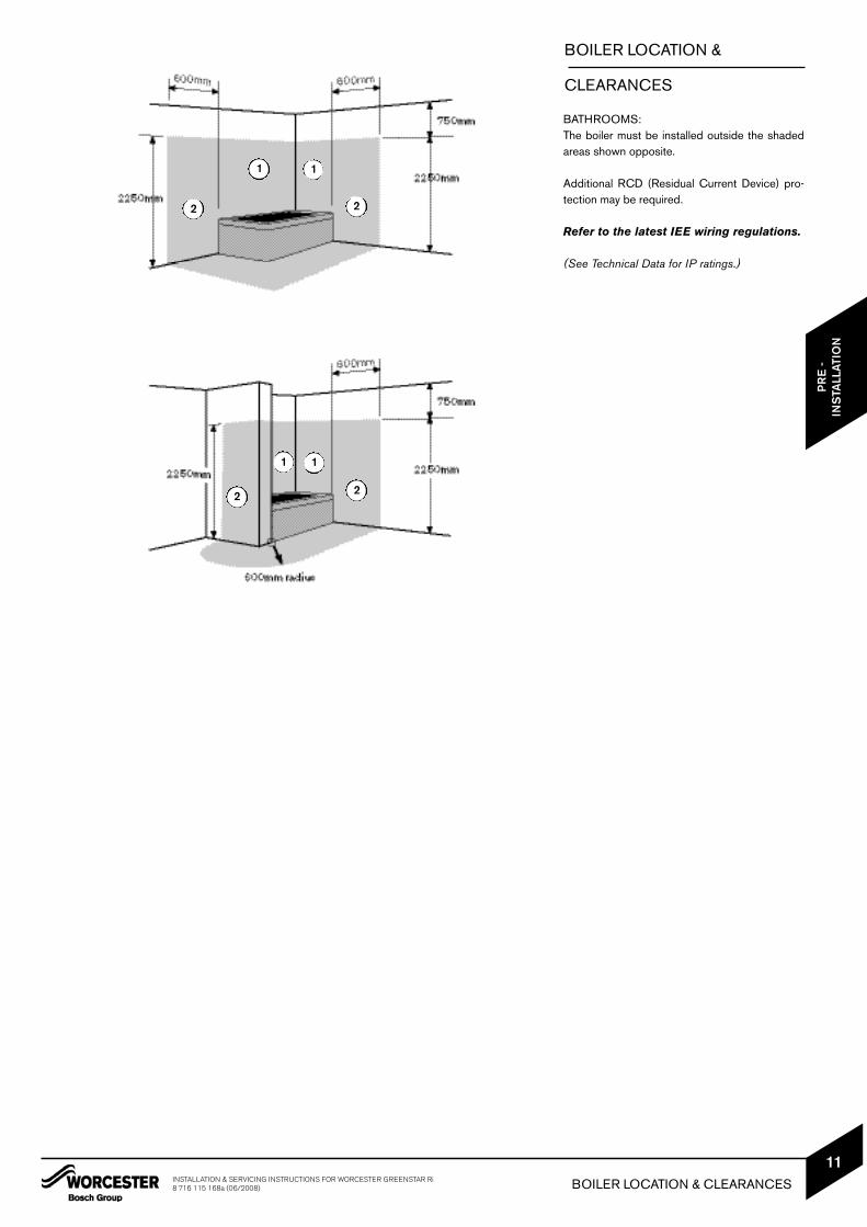
This boiler is only suitable for installing internallywithin a property at a suitable location onto afixed, rigid surface at least the same size as theboiler and capable of supporting the boilerweight.
COMPARTMENTS:Follow the requirements of BS6798 andBS5440 Part 2 and note:• Minimum clearances must be maintained• An access door is required to install, service
and maintain the boiler and any ancilliary equipment.
• If fitting the boiler into an airing cupboard use a non-combustible material (which can be perforated with holes upto 13mm diameter) to seperate the boiler from the airing space.
BOILER CLEARANCES:The diagram opposite shows the minimumspace required to install and service the boiler.
If a boiler is installed in a compartment withclearances less than shown in the tables oppo-site, ventilation is required. Refer to tablesbelow for ventilation requirements.
BOILER CLEARANCES - UNVENTILATED COMPARTMENTS:The tables opposite show the options for theminimum space required to install and servicethe boiler inside an unventilated compartment.
*NOTE: These are the combined top & bottom clearances excluding the appliance.
**NOTE: These are the combined left & right clearances excluding the appliance.
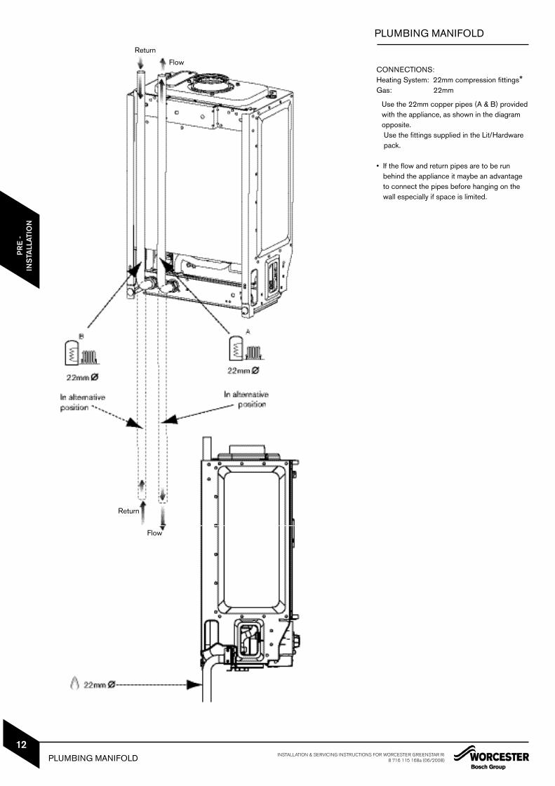
Use the 22mm copper pipes (A & B) providedwith the appliance, as shown in the diagramopposite. Use the fittings supplied in the Lit/Hardware pack.
• If the flow and return pipes are to be run behind the appliance it maybe an advantage to connect the pipes before hanging on the wall especially if space is limited.
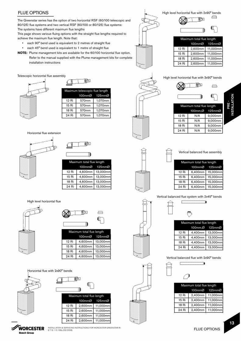
The Greenstar series has the option of two horizontal RSF (60/100 telescopic and80/125) flue systems and two vertical RSF (60/100 or 80/125) flue systems:The systems have different maximum flue lengthsThis page shows various fluing options with the straight flue lengths required to achieve the maximum flue length. Note that:
• each 90° bend used is equivalent to 2 metres of straight flue• each 45° bend used is equivalent to 1 metre of straight flue
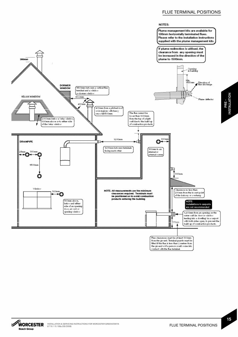
NOTE: Plume management kits are available for the 60/100 horizontal flue option.Refer to the manual supplied with the Plume management kits for complete installation instructions
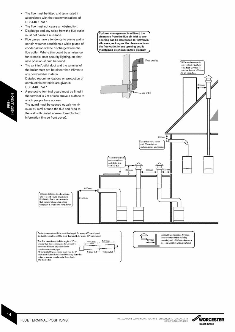
• The flue must be fitted and terminated inaccordance with the recommendations ofBS5440 : Part 1.
• The flue must not cause an obstruction.• Discharge and any noise from the flue outlet
must not cause a nuisance.• Flue gases have a tendency to plume and in
certain weather conditions a white plume ofcondensation will be discharged from theflue outlet. Where this could be a nuisance,for example, near security lighting, an alter-nate position should be found.
• The air inlet/outlet duct and the terminal ofthe boiler must not be closer than 25mm toany combustible material. Detailed recommendations on protection ofcombustible materials are given inBS 5440: Part 1
• A protective terminal guard must be fitted ifthe terminal is 2m or less above a surface towhich people have access.The guard must be spaced equally (mini-mum 50 mm) around the flue and fixed tothe wall with plated screws. See ContactInformation (inside front cover).
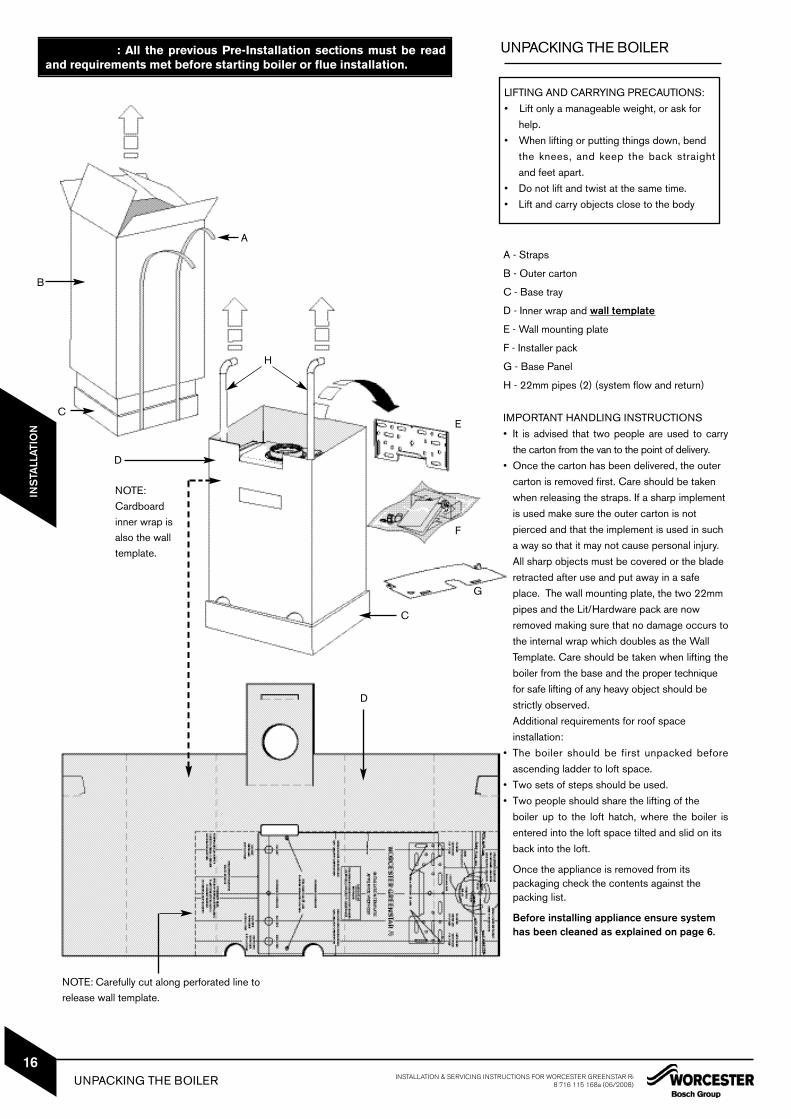
IMPORTANT HANDLING INSTRUCTIONS• It is advised that two people are used to carry
the carton from the van to the point of delivery.• Once the carton has been delivered, the outer
carton is removed first. Care should be taken when releasing the straps. If a sharp implement is used make sure the outer carton is not pierced and that the implement is used in such a way so that it may not cause personal injury. All sharp objects must be covered or the blade retracted after use and put away in a safe place. The wall mounting plate, the two 22mm pipes and the Lit/Hardware pack are now removed making sure that no damage occurs tothe internal wrap which doubles as the Wall Template. Care should be taken when lifting theboiler from the base and the proper technique for safe lifting of any heavy object should be strictly observed.Additional requirements for roof space installation:
• The boiler should be first unpacked beforeascending ladder to loft space.
• Two sets of steps should be used.• Two people should share the lifting of the
boiler up to the loft hatch, where the boiler isentered into the loft space tilted and slid on its back into the loft.
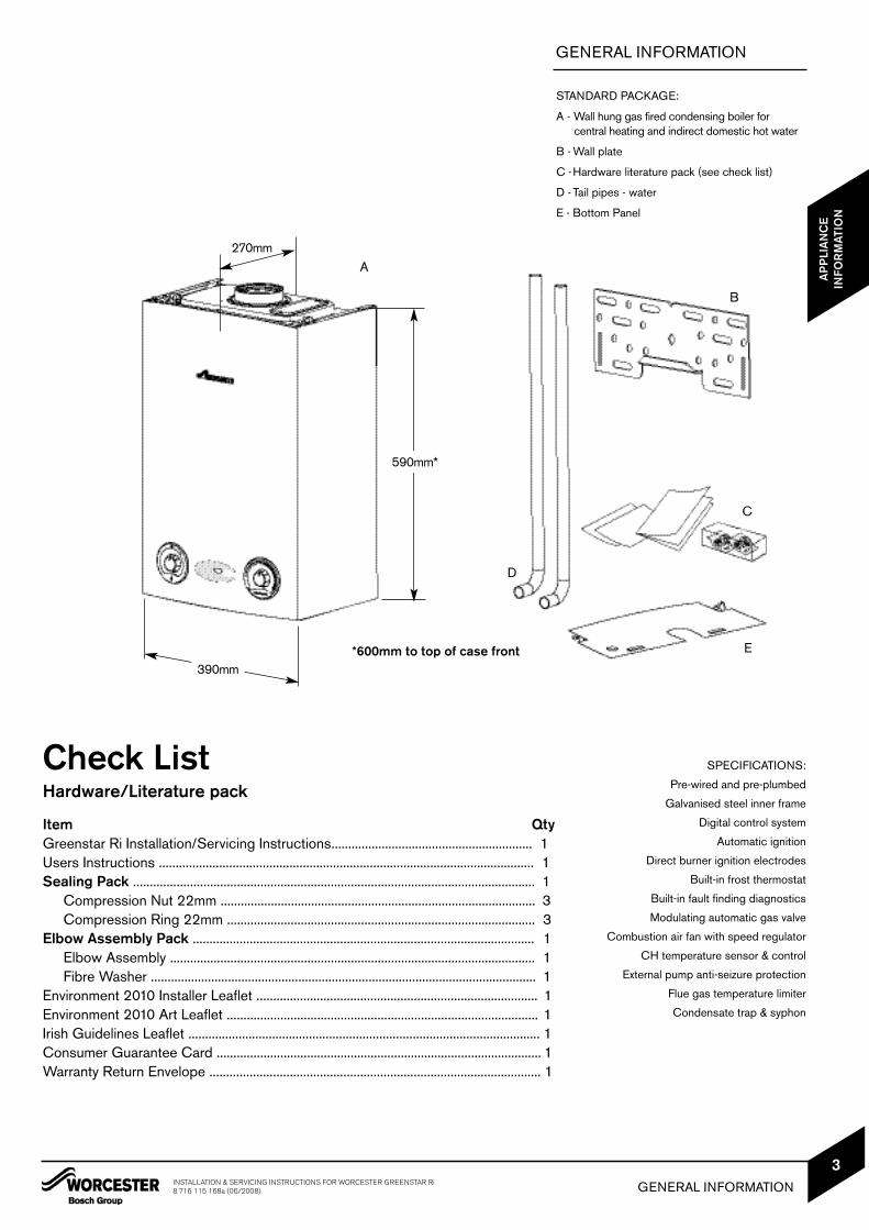
Once the appliance is removed from its packaging check the contents against the packing list.
Before installing appliance ensure system has been cleaned as explained on page 6.
UNPACKING THE BOILER
LIFTING AND CARRYING PRECAUTIONS:• Lift only a manageable weight, or ask for
help. • When lifting or putting things down, bend
the knees, and keep the back straight and feet apart.
• Do not lift and twist at the same time. • Lift and carry objects close to the body
IMPORTANT: All the previous Pre-Installation sections must be readand requirements met before starting boiler or flue installation.
E
F
NOTE:Cardboardinner wrap isalso the wall template.
NOTE: Carefully cut along perforated line torelease wall template.
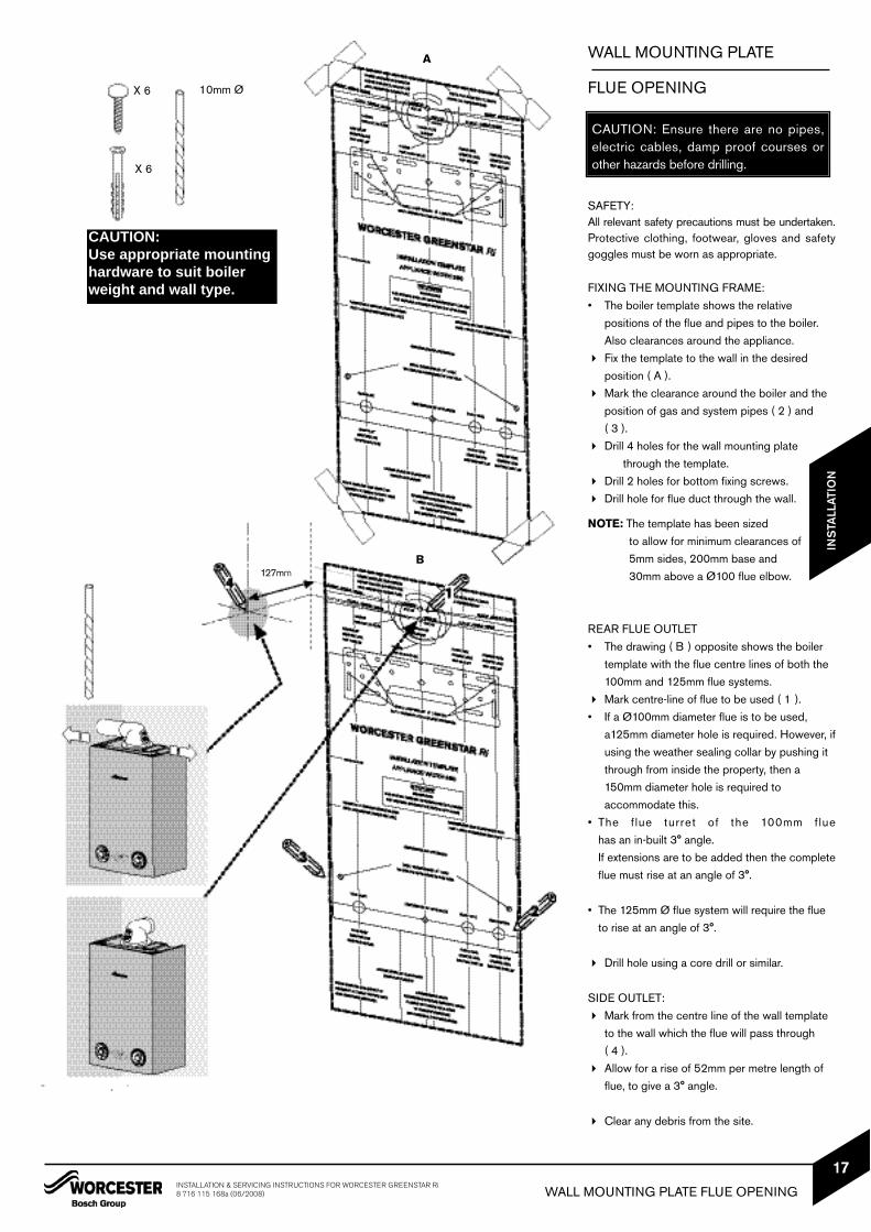
SAFETY:All relevant safety precautions must be undertaken.Protective clothing, footwear, gloves and safetygoggles must be worn as appropriate.
FIXING THE MOUNTING FRAME:• The boiler template shows the relative
positions of the flue and pipes to the boiler. Also clearances around the appliance.
Fix the template to the wall in the desired position ( A ).
Mark the clearance around the boiler and the position of gas and system pipes ( 2 ) and ( 3 ).
Drill 4 holes for the wall mounting plate through the template.
Drill 2 holes for bottom fixing screws. Drill hole for flue duct through the wall.
NOTE: The template has been sized to allow for minimum clearances of5mm sides, 200mm base and 30mm above a Ø100 flue elbow.
REAR FLUE OUTLET• The drawing ( B ) opposite shows the boiler
template with the flue centre lines of both the 100mm and 125mm flue systems.
Mark centre-line of flue to be used ( 1 ).• If a Ø100mm diameter flue is to be used,
a125mm diameter hole is required. However, ifusing the weather sealing collar by pushing it through from inside the property, then a 150mm diameter hole is required to accommodate this.
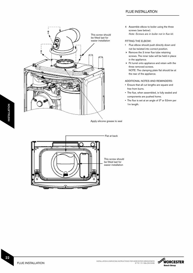
• The f lue turret of the 100mm flue has an in-built 3° angle.If extensions are to be added then the completeflue must rise at an angle of 3°.
• The 125mm Ø flue system will require the flue to rise at an angle of 3°.
Drill hole using a core drill or similar.
SIDE OUTLET: Mark from the centre line of the wall template
to the wall which the flue will pass through ( 4 ).
Allow for a rise of 52mm per metre length of flue, to give a 3° angle.
Clear any debris from the site.
CAUTION: Ensure there are no pipes,electric cables, damp proof courses orother hazards before drilling.
X 6
X 6
10mm Ø
WALL MOUNTING PLATE
FLUE OPENING
127mm
CO
MM
ISS
ION
ING
A
B
CAUTION: Use appropriate mountinghardware to suit boilerweight and wall type.
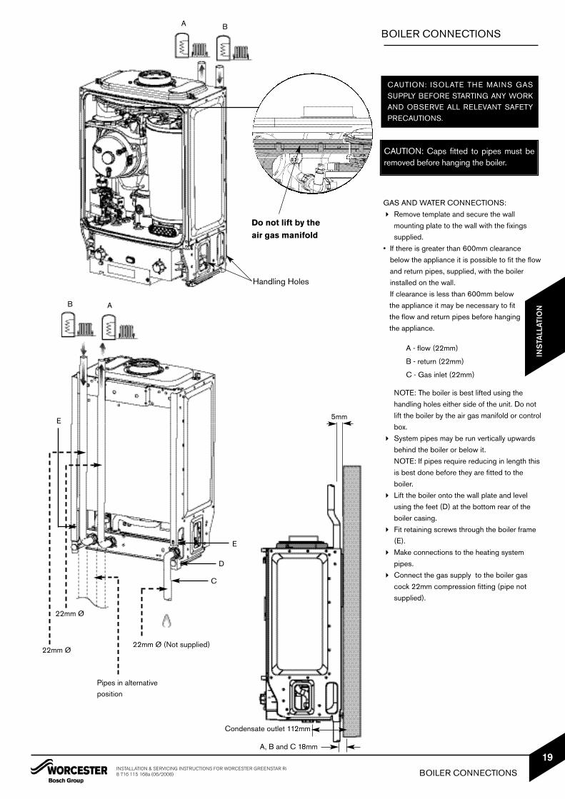
GAS AND WATER CONNECTIONS: Remove template and secure the wall
mounting plate to the wall with the fixings supplied.
• If there is greater than 600mm clearance below the appliance it is possible to fit the flow and return pipes, supplied, with the boiler installed on the wall.If clearance is less than 600mm belowthe appliance it may be necessary to fitthe flow and return pipes before hangingthe appliance.
A - flow (22mm)
B - return (22mm)
C - Gas inlet (22mm)
NOTE: The boiler is best lifted using the handling holes either side of the unit. Do not lift the boiler by the air gas manifold or control box.
System pipes may be run vertically upwards behind the boiler or below it.NOTE: If pipes require reducing in length this is best done before they are fitted to the boiler.
Lift the boiler onto the wall plate and level using the feet (D) at the bottom rear of the boiler casing.
Fit retaining screws through the boiler frame (E).
Make connections to the heating system pipes.
Connect the gas supply to the boiler gas cock 22mm compression fitting (pipe not supplied).
BOILER CONNECTIONS
CAUTION: ISOLATE THE MAINS GASSUPPLY BEFORE STARTING ANY WORKAND OBSERVE ALL RELEVANT SAFETYPRECAUTIONS.
22mm Ø
22mm Ø
22mm Ø (Not supplied)
5mm
Pipes in alternativeposition
AB
A B
D
E
C
E
Handling Holes
Do not lift by theair gas manifold
Condensate outlet 112mm
A, B and C 18mm
CAUTION: Caps fitted to pipes must beremoved before hanging the boiler.
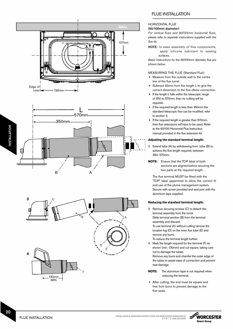
HORIZONTAL FLUE(60/100mm diameter)For vertical flues and 80/125mm horizontal flues,please refer to separate instructions supplied with theflue kit.
NOTE: to ease assembly of flue components,apply silicone lubricant to sealing
surfaces.Basic instructions for the 60/100mm diameter flue areshown below.
MEASURING THE FLUE (Standard Flue): Measure from the outside wall to the centre
line of the flue turret. Subtract 93mm from the length L to give the
correct dimension to the flue elbow connection. If the length L falls within the telescopic range
of 350 to 570mm, then no cutting will be required.
If the required length is less than 350mm the standard telescopic flue can be modified, refer to section 3.
If the required length is greater than 570mm, then flue extensions will have to be used. Refer to the 60/100 Horizontal Flue Instruction manual provided in the flue extension kit.
Adjusting the standard terminal length:
2 Extend tube (A) by withdrawing from tube (B) to achieve the flue length required, between 350- 570mm.
NOTE: Ensure that the TOP label of both sections are aligned before securing thetwo parts at the required length.
The flue terminal MUST be fitted with the 'TOP' label uppermost to allow the correct fitand use of the plume management system.Secure with screw provided and seal joint with the aluminium tape supplied.
Reducing the standard terminal length:
3 Remove securing screws (C) to detach the terminal assembly from the turret.Slide terminal section (B) from the terminal assembly and discard.To use terminal (A) without cutting remove the location lug (D) on the inner flue tube (E) and remove any burrs.To reduce the terminal length further:
4 Mark the length required for the terminal (F) as shown (min. 130mm) and cut square, taking care not to damage the tubes.Remove any burrs and chamfer the outer edge of the tubes to assist ease of connection and prevent seal damage.
NOTE: The aluminium tape is not required when reducing the terminal.
After cutting, the end must be square and free from burrs to prevent damage to the flue seals.
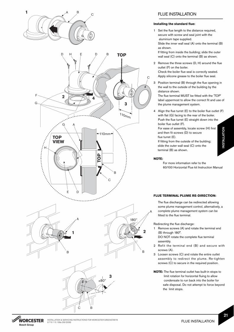
1 Set the flue length to the distance required, secure with screw and seal joint with thealuminium tape supplied. Slide the inner wall seal (A) onto the terminal (B) as shown.If fitting from inside the building; slide the outer wall seal (C) onto the terminal (B) as shown.
2 Remove the three screws (D, H) around the flue outlet (F) on the boiler. Check the boiler flue seal is correctly seated.Apply silicone grease to the boiler flue seal.
3 Position terminal (B) through the flue opening in the wall to the outside of the building by the distance shown.The flue terminal MUST be fitted with the 'TOP' label uppermost to allow the correct fit and use ofthe plume management system.
4 Align the flue turret (E) to the boiler flue outlet (F) with flat (G) facing to the rear of the boiler.Push the flue turret (E) straight down into theboiler flue outlet (F).For ease of assembly, locate screw (H) firstand then fit screws (D) to secure flue turret (E).If fitting from the outside of the building;slide the outer wall seal (C) onto the terminal (B) as shown.
NOTE: For more information refer to the 60/100 Horizontal Flue kit Instruction Manual
FLUE TERMINAL PLUME RE-DIRECTION:
The flue discharge can be redirected allowing some plume management control, alternatively, a complete plume management system can be fitted to the flue terminal.
Redirecting the flue discharge:1 Remove screws (A) and rotate the terminal end
(B) through 180°.DO NOT rotate the complete flue terminal assembly.
2 Refit the terminal end (B) and secure with screws (A).
3 Loosen screws (C) and rotate the entire outlet assembly to redirect the plume. Re-tighten screws (C) to secure in the required position.
NOTE: The flue terminal outlet has built-in stops to limit rotation for horizontal fluing to allow condensate to run back into the boiler for safe disposal. Do not attempt to force beyondthe limit stops.
CAUTION: ISOLATE THE MAINS SUPPLIES BEFORE STARTING ANYWORK AND OBSERVE ALL RELEVANT SAFETY PRECAUTIONS
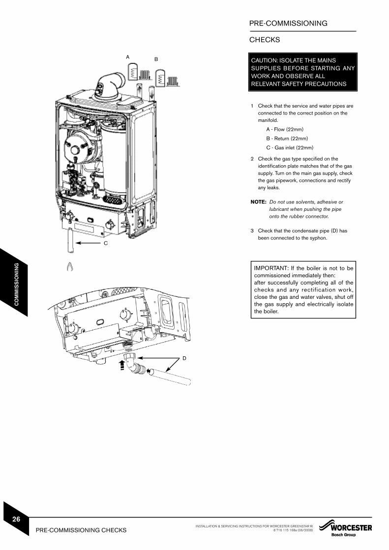
1 Check that the service and water pipes are connected to the correct position on the manifold.
A - Flow (22mm)
B - Return (22mm)
C - Gas inlet (22mm)
2 Check the gas type specified on the identification plate matches that of the gas supply. Turn on the main gas supply, check the gas pipework, connections and rectify any leaks.
NOTE: Do not use solvents, adhesive or lubricant when pushing the pipe onto the rubber connector.
3 Check that the condensate pipe (D) has been connected to the syphon.
IMPORTANT: If the boiler is not to becommissioned immediately then:after successfully completing all of thechecks and any rectification work,close the gas and water valves, shut offthe gas supply and electrically isolatethe boiler.
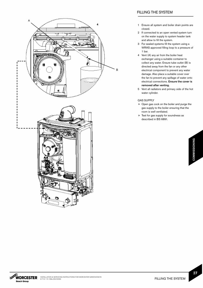
1 Ensure all system and boiler drain points areclosed.
2 If connected to an open vented system turn on the water supply to system header tank and allow to fill the system.
3 For sealed systems fill the system using a WRAS approved filling loop to a pressure of1 bar.
4 Vent (A) any air from the boiler heat exchanger using a suitable container to collect any water. Ensure tube outlet (B) is directed away from the fan or any other electrical component to prevent any water damage. Also place a suitable cover over the fan to prevent any spillage of water onto electrical connections. Ensure the cover is removed after venting.
5 Vent all radiators and primary side of the hotwater cylinder.
GAS SUPPLY Open gas cock on the boiler and purge the
gas supply to the boiler ensuring that the room is well ventilated.
Test for gas supply for soundness as described in BS 6891.
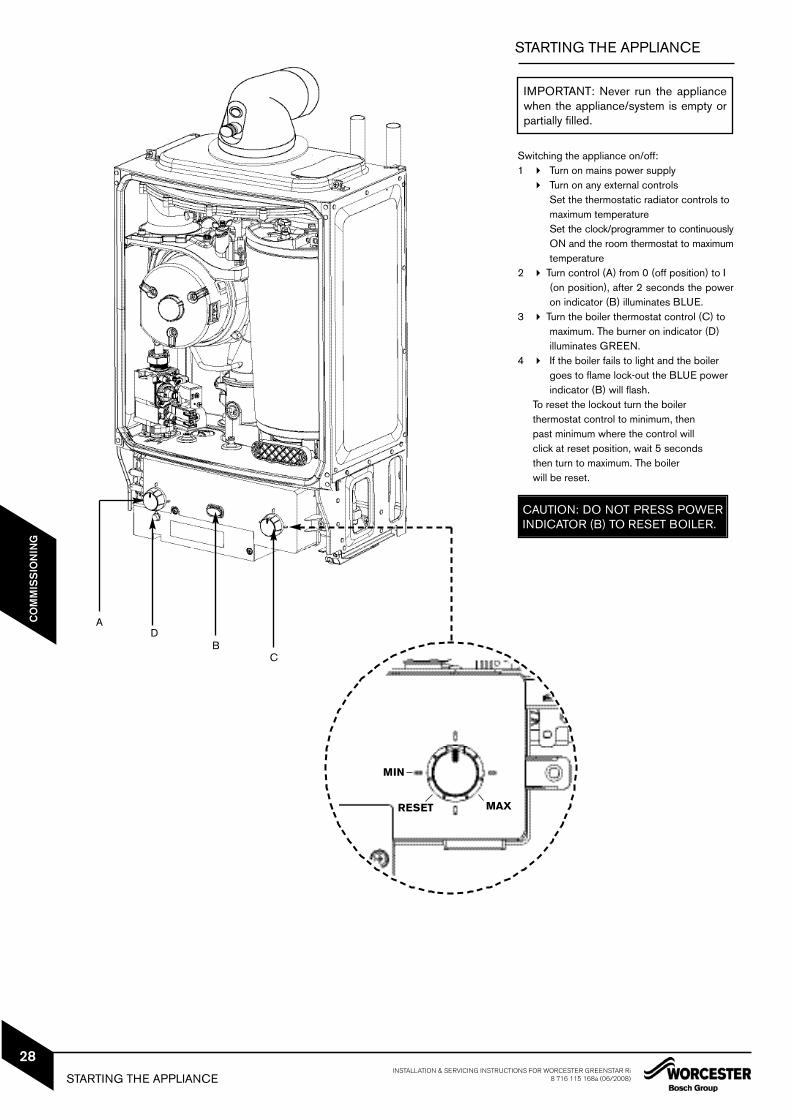
Switching the appliance on/off:1 Turn on mains power supply
Turn on any external controlsSet the thermostatic radiator controls to maximum temperatureSet the clock/programmer to continuouslyON and the room thermostat to maximumtemperature
2 Turn control (A) from 0 (off position) to I (on position), after 2 seconds the poweron indicator (B) illuminates BLUE.
3 Turn the boiler thermostat control (C) to maximum. The burner on indicator (D) illuminates GREEN.
4 If the boiler fails to light and the boiler goes to flame lock-out the BLUE power indicator (B) will flash.
To reset the lockout turn the boiler thermostat control to minimum, then past minimum where the control will click at reset position, wait 5 seconds then turn to maximum. The boiler will be reset.
STARTING THE APPLIANCE
IMPORTANT: Never run the appliancewhen the appliance/system is empty orpartially filled.
AD
BC
MIN
MAXRESET
CAUTION: DO NOT PRESS POWERINDICATOR (B) TO RESET BOILER.
IMPORTANT: Debris from the systemcan damage the boiler and reduce effi-ciency. Failure to comply with theguidelines for the use of water treat-ment with the appliance will invalidatethe appliance warranty.
ENSURE THAT THE SYSTEM HAS BEENCLEANED AS ON PAGE 6 OF THESEINSTRUCTIONS.
FLUSHING (Central Heating): Switch off the boiler. If connected to an
open vented system turn OFF the water supply to the system header tank
Open all drain cocks and drain the system while the appliance is hot.
Close drain cocks and add a suitable flushing agent at the correct strength forthe system condition in accordance with themanufacturer's instructions.
Run the boiler/system at normal operatingtemperature for the time stated by the manufacturer of the flushing agent.
Drain and thoroughly flush the system to remove the flushing agent and debris.
INHIBITOR (Central Heating):
Check drain cocks are closed and all radiator valves are open before adding a suitable*inhibitor (or combined inhibitor/anti-freeze if the system is exposed to freezing conditions) to the heating system water inaccordance with the manufacturers instructions.
* compatible with aluminium. The pHvalue of the system water must be lessthan 8 or the appliance guarantee will beinvalidated. If connected to an open vent system turn on
the water supply to the system header tank and allow to fill the system.If connected to a sealed system fill via a WRAS approved filling loop to between 1 and 2 bar.
Vent all radiators; Re-tighten vents when complete. Vent any air from the boiler heat exchanger using a suitable container tocollect any water.
Ensure tube outlet is directed away fromthe fan or any other electrical component to prevent damage.
Vent all radiators and the primary side of thehot water tank.
For sealed systems re-pressurise if necessary.
Turn pressure relief valve anti-clockwise untilthe pressure is 1bar.
Set all controls to maximum.
Record the date when the inhibitor was added to the system on the guarantee card.
NOTE: The concentration level ofinhibitor in the system should bechecked every 12 months orsooner if system content is lost.
The addition of sealing agents tothe system water is notrecommended as this can causeproblems with deposits left in theheat exchanger.
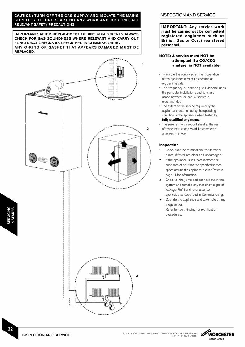
NOTE: A service must NOT beattempted if a CO/CO2analyser is NOT available.
• To ensure the continued efficient operation of the appliance it must be checked at regular intervals.
• The frequency of servicing will depend uponthe particular installation conditions and usage however, an annual service is recommended .
• The extent of the service required by the appliance is determined by the operating condition of the appliance when tested by fully qualified engineers.
• The service interval record sheet at the rear of these instructions must be completed after each service.
Inspection1 Check that the terminal and the terminal
guard, if fitted, are clear and undamaged.
2 If the appliance is in a compartment or
cupboard check that the specified service
space around the appliance is clear. Refer to
page 11 for information.
3 Check all the joints and connections in the
system and remake any that show signs of
leakage. Refill and re-pressurise if
applicable as described in Commissioning.
Operate the appliance and take note of any
irregularities.
Refer to Fault Finding for rectification
procedures.
IMPORTANT: Any service workmust be carried out by competentregistered engineers such asBritish Gas or Corgi registered personnel.
CAUTION: TURN OFF THE GAS SUPPLY AND ISOLATE THE MAINSSUPPLIES BEFORE STARTING ANY WORK AND OBSERVE ALLRELEVANT SAFETY PRECAUTIONS.
IMPORTANT: AFTER REPLACEMENT OF ANY COMPONENTS ALWAYSCHECK FOR GAS SOUNDNESS WHERE RELEVANT AND CARRY OUTFUNCTIONAL CHECKS AS DESCRIBED IN COMMISSIONING.ANY O-RING OR GASKET THAT APPEARS DAMAGED MUST BEREPLACED.
1
2
3
INSPECTION AND SERVICE INSTALLATION & SERVICING INSTRUCTIONS FOR WORCESTER GREENSTAR Ri8 716 115 168a (06/2008)
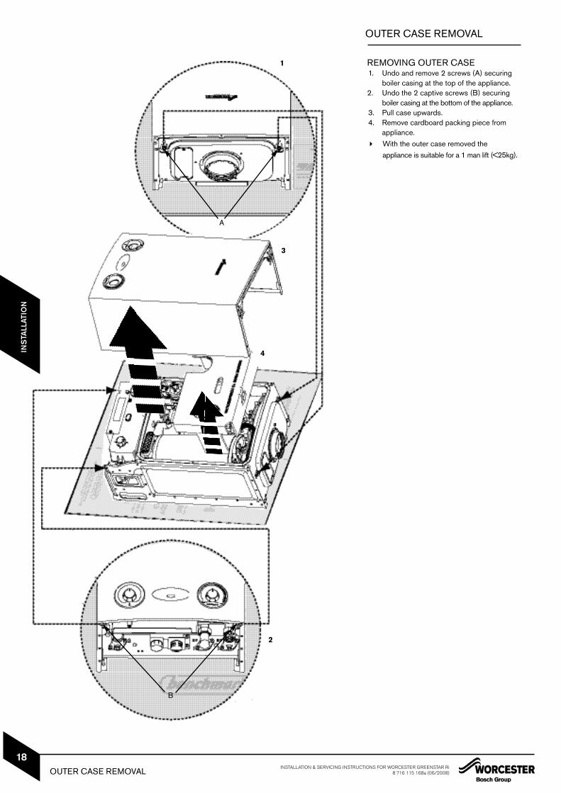
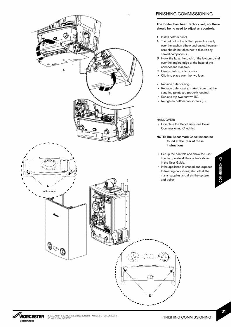
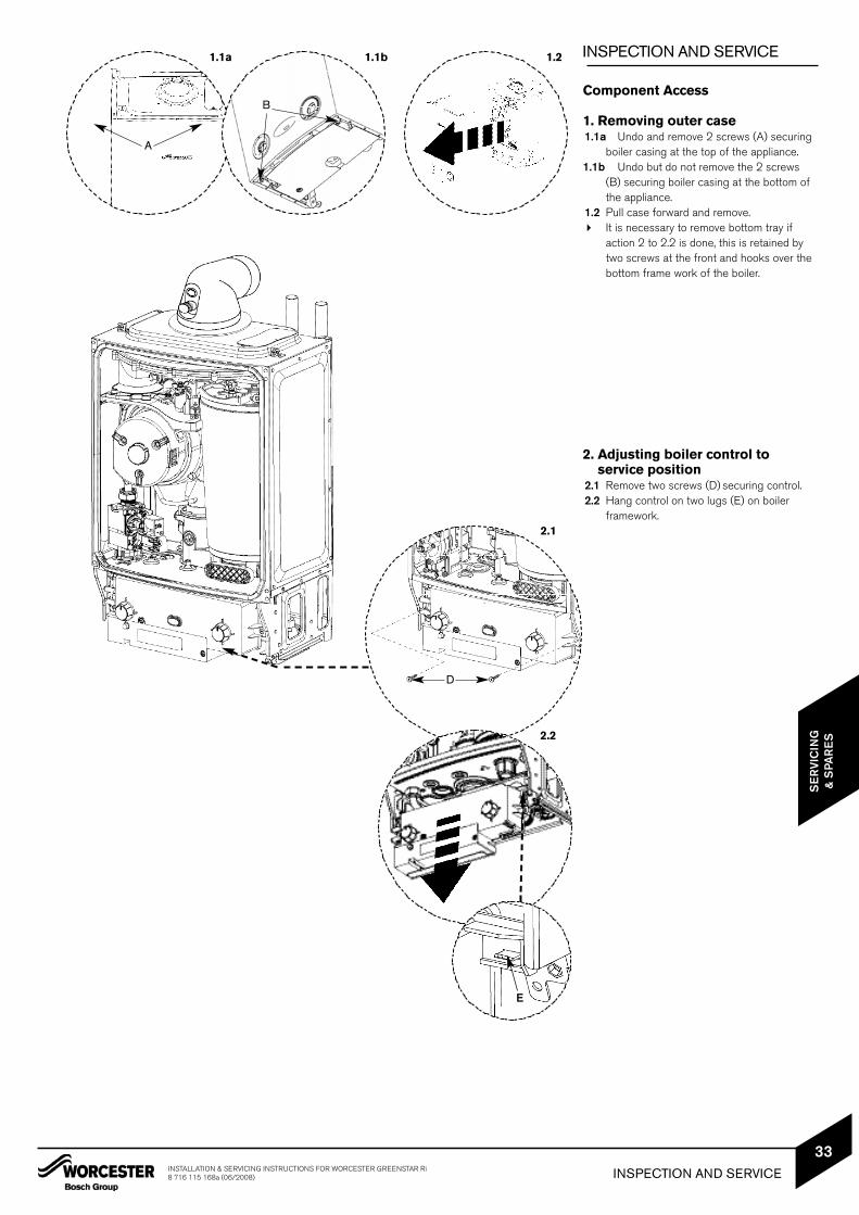
boiler casing at the top of the appliance.1.1b Undo but do not remove the 2 screws
(B) securing boiler casing at the bottom of the appliance.
1.2 Pull case forward and remove. It is necessary to remove bottom tray if
action 2 to 2.2 is done, this is retained by two screws at the front and hooks over the bottom frame work of the boiler.
2. Adjusting boiler control to service position
2.1 Remove two screws (D) securing control.2.2 Hang control on two lugs (E) on boiler
framework.
3
A
1.1a 1.1b 1.2
B
2.1
2.2
D
E
INSPECTION AND SERVICEINSTALLATION & SERVICING INSTRUCTIONS FOR WORCESTER GREENSTAR Ri8 716 115 168a (06/2008)
33
SE
RVI
CIN
G&
SPA
RE
S
INSPECTION AND SERVICE
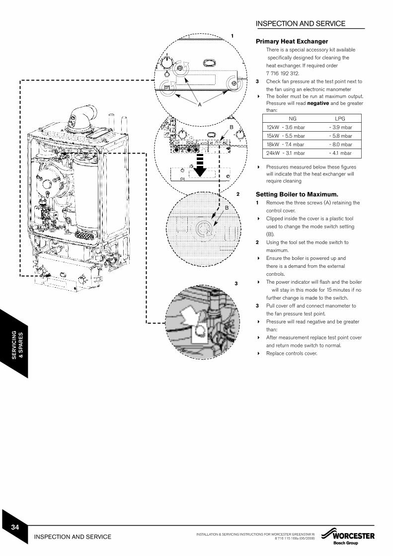
Primary Heat ExchangerThere is a special accessory kit available
specifically designed for cleaning the
heat exchanger. If required order
7 716 192 312.
3 Check fan pressure at the test point next to
the fan using an electronic manometer The boiler must be run at maximum output.
Pressure will read negative and be greaterthan:
NG LPG
12kW - 3.6 mbar - 3.9 mbar
15kW - 5.5 mbar - 5.8 mbar
18kW - 7.4 mbar - 8.0 mbar
24kW - 3.1 mbar - 4.1 mbar
Pressures measured below these figures will indicate that the heat exchanger will require cleaning
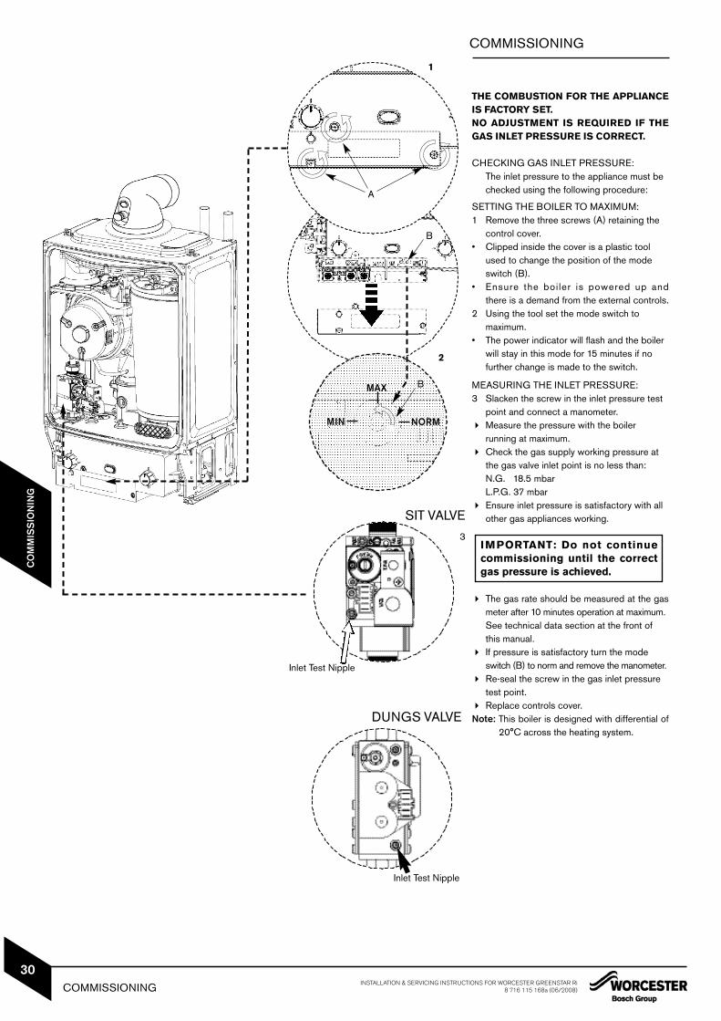
Setting Boiler to Maximum.1 Remove the three screws (A) retaining the
control cover.
Clipped inside the cover is a plastic tool
used to change the mode switch setting
(B).
2 Using the tool set the mode switch to
maximum.
Ensure the boiler is powered up and
there is a demand from the external
controls.
The power indicator will flash and the boiler
will stay in this mode for 15 minutes if no
further change is made to the switch.
3 Pull cover off and connect manometer to
the fan pressure test point.
Pressure will read negative and be greater
than:
After measurement replace test point cover
and return mode switch to normal.
Replace controls cover.
1
A
B
B
2
3
INSPECTION AND SERVICE INSTALLATION & SERVICING INSTRUCTIONS FOR WORCESTER GREENSTAR Ri8 716 115 168a (06/2008)
34
SE
RVI
CIN
G&
SPA
RE
S
INSPECTION AND SERVICE1
A
B
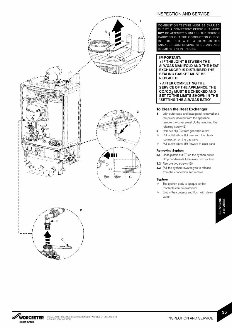
3To Clean the Heat Exchanger1 With outer case and base panel removed and
the power isolated from the appliance, remove the cover panel (A) by removing the retaining screw (B)
2 Remove clip (C) from gas valve outlet Pull outlet elbow (E) free from the plastic
connection on the gas valve Pull outlet elbow (E) forward to clear case
Removing Syphon3.1 Undo plastic nut (F) on the syphon outlet
Drop condensate tube away from syphon3.2 Remove two screws (G)3.3 Pull the syphon towards you to release
from the connection and remove
Syphon The syphon body is opaque so that
contents can be examined Empty the contents and flush with clean
water
COMBUSTION TESTING MUST BE CARRIEDOUT BY A COMPETENT PERSON. IT MUSTNOT BE ATTEMPTED UNLESS THE PERSONCARRYING OUT THE COMBUSTION CHECKI S E Q U I P P E D W ITH A C O M B U STI O NANALYSER CONFORMING TO BS 7927 ANDIS COMPETENT IN IT’S USE.
G
F
2
C
E
INSPECTION AND SERVICEINSTALLATION & SERVICING INSTRUCTIONS FOR WORCESTER GREENSTAR Ri8 716 115 168a (06/2008)
35
SE
RVI
CIN
G&
SPA
RE
S
IMPORTANT:IF THE JOINT BETWEEN THEAIR/GAS MANIFOLD AND THE HEATEXCHANGER IS DISTURBED THESEALING GASKET MUST BEREPLACED.AFTER COMPLETING THESERVICE OF THE APPLIANCE, THECO/CO2 MUST BE CHECKED ANDSET TO THE LIMITS SHOWN IN THE“SETTING THE AIR/GAS RATIO”
INSPECTION AND SERVICE
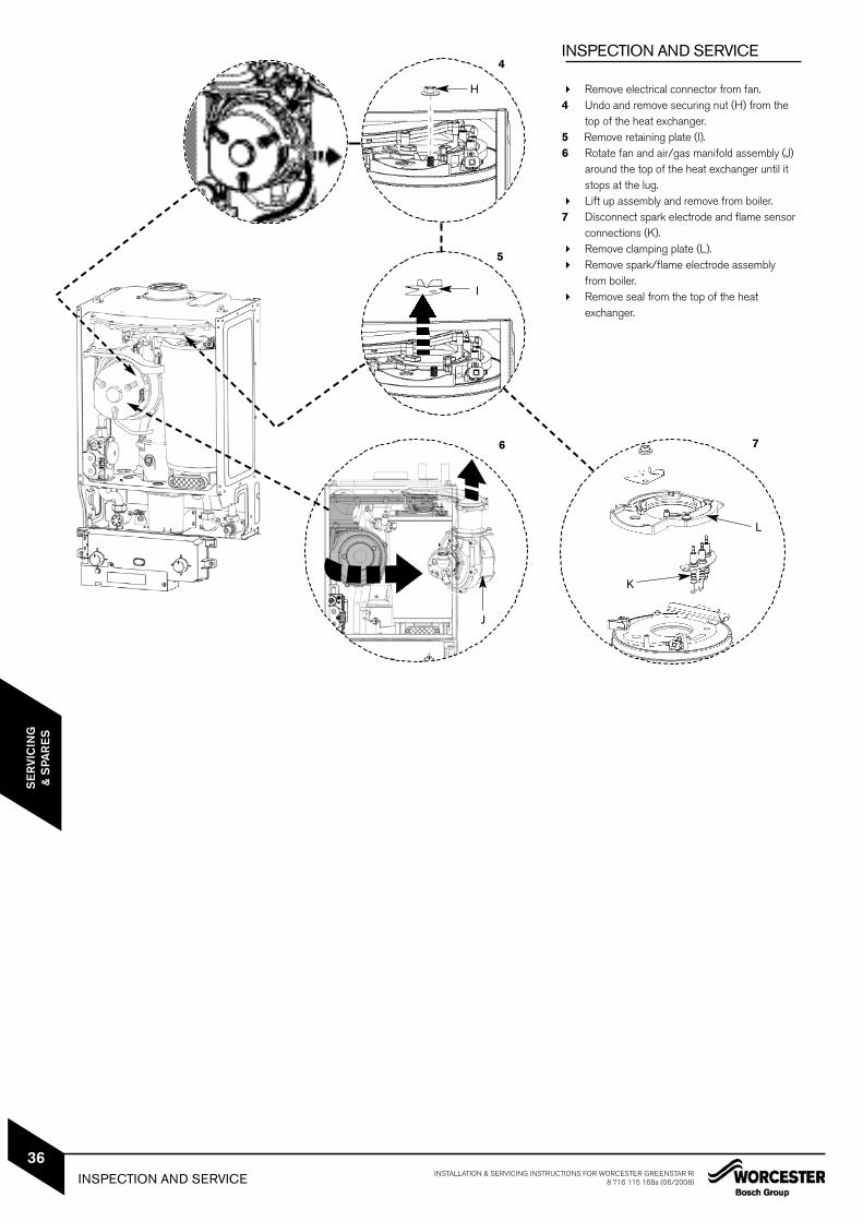
Remove electrical connector from fan.4 Undo and remove securing nut (H) from the
top of the heat exchanger.5 Remove retaining plate (I).6 Rotate fan and air/gas manifold assembly (J)
around the top of the heat exchanger until it stops at the lug.
Lift up assembly and remove from boiler.7 Disconnect spark electrode and flame sensor
INSPECTION AND SERVICE INSTALLATION & SERVICING INSTRUCTIONS FOR WORCESTER GREENSTAR Ri8 716 115 168a (06/2008)
36
SE
RVI
CIN
G&
SPA
RE
S
INSPECTION AND SERVICE
8
M
N
O
P
Q
R
S
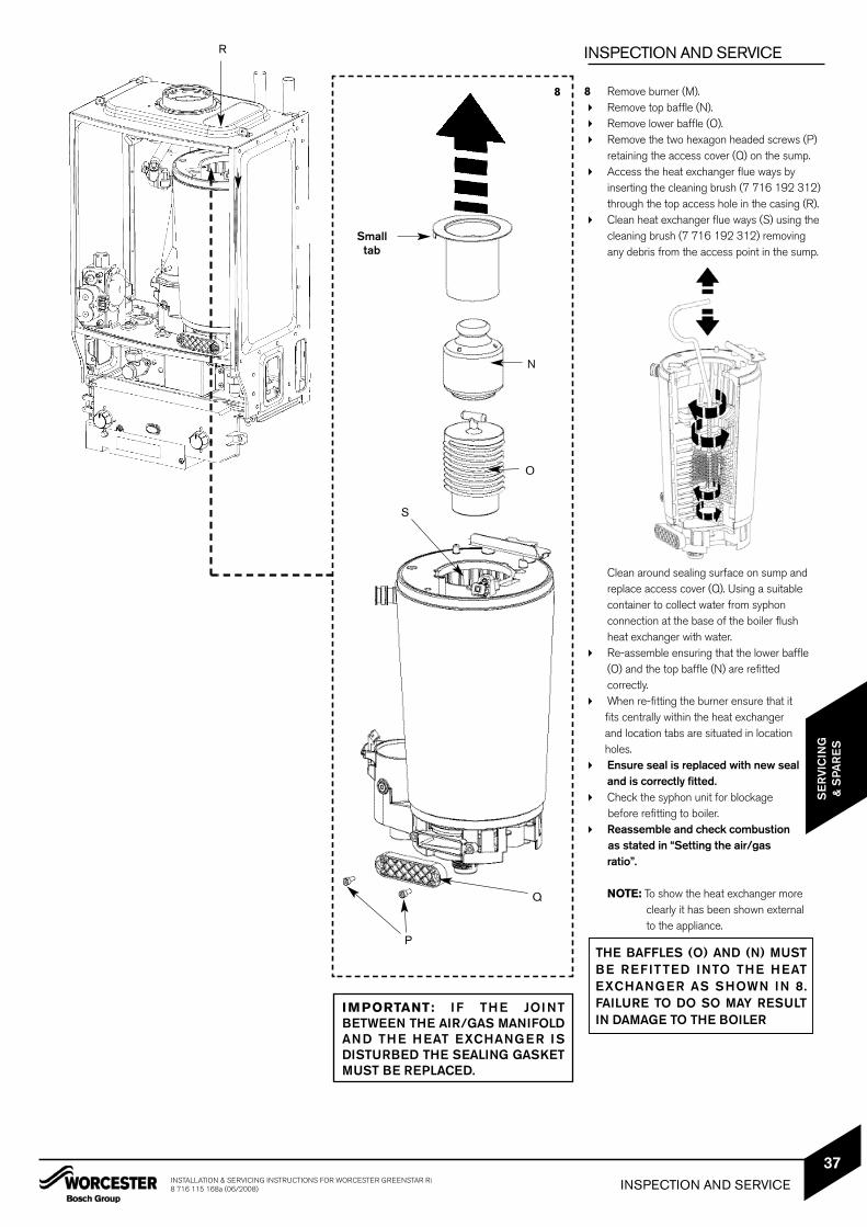
8 Remove burner (M). Remove top baffle (N). Remove lower baffle (O). Remove the two hexagon headed screws (P)
retaining the access cover (Q) on the sump. Access the heat exchanger flue ways by
inserting the cleaning brush (7 716 192 312)through the top access hole in the casing (R).
Clean heat exchanger flue ways (S) using thecleaning brush (7 716 192 312) removing any debris from the access point in the sump.
Clean around sealing surface on sump and replace access cover (Q). Using a suitable container to collect water from syphon connection at the base of the boiler flush heat exchanger with water.
Re-assemble ensuring that the lower baffle (O) and the top baffle (N) are refitted correctly.
When re-fitting the burner ensure that it fits centrally within the heat exchanger and location tabs are situated in locationholes.
Ensure seal is replaced with new seal and is correctly fitted.
Check the syphon unit for blockage before refitting to boiler.
Reassemble and check combustionas stated in “Setting the air/gas ratio”.
NOTE: To show the heat exchanger moreclearly it has been shown externalto the appliance.
THE BAFFLES (O) AND (N) MUSTBE REFITTED INTO THE HEATEXCHANGER AS SHOWN IN 8.FAILURE TO DO SO MAY RESULTIN DAMAGE TO THE BOILER
IMPORTANT: IF THE JOINTBETWEEN THE AIR/GAS MANIFOLDAND THE HEAT EXCHANGER ISDISTURBED THE SEALING GASKETMUST BE REPLACED.
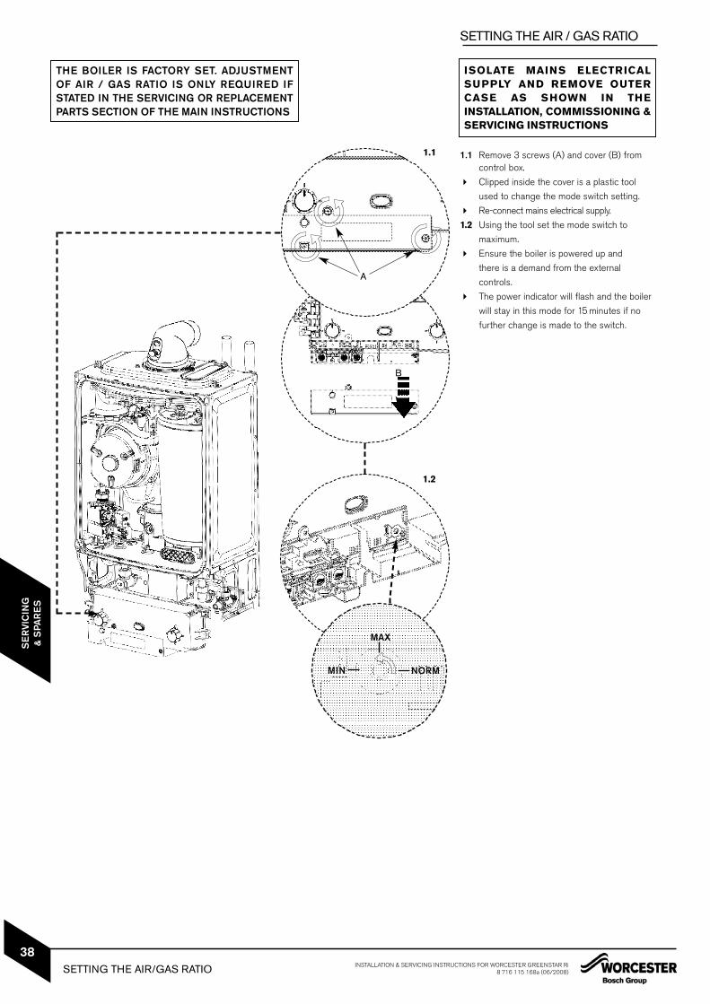
1.1 Remove 3 screws (A) and cover (B) from control box.
Clipped inside the cover is a plastic tool
used to change the mode switch setting.
Re-connect mains electrical supply.
1.2 Using the tool set the mode switch to
maximum.
Ensure the boiler is powered up and
there is a demand from the external
controls.
The power indicator will flash and the boiler
will stay in this mode for 15 minutes if no
further change is made to the switch.
MAX
NORMMIN
THE BOILER IS FACTORY SET. ADJUSTMENTOF AIR / GAS RATIO IS ONLY REQUIRED IFSTATED IN THE SERVICING OR REPLACEMENTPARTS SECTION OF THE MAIN INSTRUCTIONS
SETTING THE AIR / GAS RATIO
ISOLATE MAINS ELECTRICALSUPPLY AND REMOVE OUTERCASE AS SHOWN IN THEINSTALLATION, COMMISSIONING &SERVICING INSTRUCTIONS
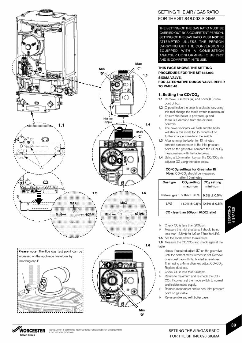
SIGMA VALVE.FOR ALTERNATIVE DUNGS VALVE REFERTO PAGE 40 .
1. Setting the CO/CO21.1 Remove 3 screws (A) and cover (B) from
control box. 1.2 Clipped inside the cover is a plastic tool, using
this tool change the mode switch to maximum. Ensure the boiler is powered up and
there is a demand from the external controls.
The power indicator will flash and the boiler will stay in this mode for 15 minutes if no further change is made to the switch.
1.3 After running the boiler for 10 minutes connect a manometer to the inlet pressure point on the gas valve, compare the CO/CO2measurement with the table below.
1.4 Using a 2.5mm allen key set the CO/CO2 via adjuster (C) using the table below.
Check CO is less than 200ppm. Measure the inlet pressure; it should be no
less than 18.5mb for NG or 37mb for LPG.1.5 Set the mode switch to minimum.1.6 Measure the CO/CO2 and check against thetable
above. If required adjust (D) on the gas valve until the correct measurement is set. Remove brass dust cap with flat bladed screwdriver. Then using a 4mm allen key adjust CO/CO2. Replace dust cap.
Check CO is less than 200ppm. Return to maximum and re-check the CO /
CO2. If correct set the mode switch to normaland isolate mains supply.
Remove manometer and re-seal inlet pressurepoint on gas valve.
Re-assemble and refit boiler case.
Gas type
CO/CO2 settings for Greenstar RiNOTE. CO/CO
2should be measured
after 10 minutes
Natural gas
LPG
9.8% ± 0.5%
11.0% ± 0.5%
9.2% ± 0.5%
10.5% ± 0.5%
CO2 settingmaximum
CO2 settingminimum
THE SETTING OF THE GAS RATIO MUST BECARRIED OUT BY A COMPETENT PERSON.SETTING OF THE GAS RATIO MUST NOT BEATTEMPTED UNLESS THE PERSONCARRYING OUT THE CONVERSION ISEQUIPPED WITH A COMBUSTIONANALYSER CONFORMING TO BS 7927AND IS COMPETENT IN ITS USE.
Please note: The flue gas test point can beaccessed on the appliance flue elbow by removing cap E
E
1.5
MAX
NORMMIN
A
B
Min ‘D’
Inlet testnipple
Max ‘C’
1.6
Min ‘D’
+I
1.41.1Max ‘C’
+i
MAX
NORMMIN
1.2
1.3
SETTING THE AIR / GAS RATIOFOR THE SIT 848.093 SIGMA
CO - less than 200ppm (0.002 ratio)
SETTING THE AIR/GAS RATIOFOR THE SIT 848.093 SIGMA
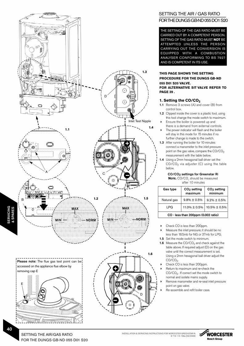
055 D01 S20 VALVE.FOR ALTERNATIVE SIT VALVE REFER TOPAGE 39 .
1. Setting the CO/CO21.1 Remove 3 screws (A) and cover (B) from
control box. 1.2 Clipped inside the cover is a plastic tool, using
this tool change the mode switch to maximum. Ensure the boiler is powered up and
there is a demand from external controls. The power indicator will flash and the boiler
will stay in this mode for 15 minutes if no further change is made to the switch.
1.3 After running the boiler for 10 minutes connect a manometer to the inlet pressure point on the gas valve, compare the CO/CO2measurement with the table below.
1.4 Using a 2mm hexagonal ball driver set the CO/CO2 via adjuster (C) using the tablebelow.
Check CO is less than 200ppm. Measure the inlet pressure; it should be no
less than 18.5mb for NG or 37mb for LPG.1.5 Set the mode switch to minimum.1.6 Measure the CO/CO2 and check against the
table above. If required adjust (D) on the gas valve until the correct measurement is set. Using a 2mm hexagonal ball driver adjust the CO/CO2.
Check CO is less than 200ppm. Return to maximum and re-check the
CO/CO2. If correct set the mode switch tonormal and isolate mains supply.
Remove manometer and re-seal inlet pressurepoint on gas valve.
Re-assemble and refit boiler case.
THE SETTING OF THE GAS RATIO MUST BECARRIED OUT BY A COMPETENT PERSON.SETTING OF THE GAS RATIO MUST NOT BEATTEMPTED UNLESS THE PERSONCARRYING OUT THE CONVERSION ISEQUIPPED WITH A COMBUSTIONANALYSER CONFORMING TO BS 7927AND IS COMPETENT IN ITS USE.
Please note: The flue gas test point can beaccessed on the appliance flue elbow by removing cap E
E
1.5
MAX
NORMMIN
A
B
1.1
MAX
NORMMIN
1.2
1.3
Inlet Test Nipple
D
1.4
+IC
1.6
D
+I
SETTING THE AIR / GAS RATIOFOR THE DUNGS GB-ND 055 DO1 S20
Gas type
CO/CO2 settings for Greenstar RiNOTE. CO/CO
2should be measured
after 10 minutes
Natural gas
LPG
9.8% ± 0.5%
11.0% ± 0.5%
9.2% ± 0.5%
10.5% ± 0.5%
CO2 settingmaximum
CO2 settingminimum
CO - less than 200ppm (0.002 ratio)
SETTING THE AIR/GAS RATIOFOR THE DUNGS GB-ND 055 D01 S20
CAUTION: TURN OFF THE GAS SUPPLY AND ISOLATE THE MAINSSUPPLIES BEFORE STARTING ANY WORK AND OBSERVE ALLRELEVANT SAFETY PRECAUTIONS.
IMPORTANT: AFTER REPLACEMENT OF ANY COMPONENTS ALWAYSCHECK FOR GAS SOUNDNESS WHERE RELEVANT AND CARRY OUTFUNCTIONAL CHECKS AS DESCRIBED IN COMMISSIONING.ANY O-RING OR GASKET THAT APPEARS DAMAGED MUST BEREPLACED.
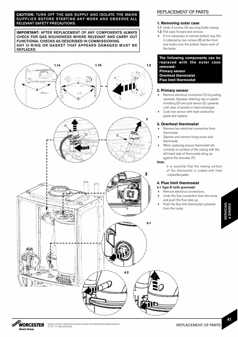
REPLACEMENT OF PARTS
1. Removing outer case1.1 Undo 4 screws (A) securing boiler casing.1.2 Pull case forward and remove. If it is necessary to remove bottom tray, this
is retained by two screws (B) at the front and hooks over the bottom frame work of the boiler.
2. Primary sensor Remove electrical connection (C) by pulling
upwards. Squeeze retaining clip on plastic moulding (D) and pull sensor (E) upwards until clear of pocket in heat exchanger.
Coat new sensor with heat conductive paste and replace.
3. Overheat thermostat Remove two electrical connectors from
thermostat. Slacken and remove fixing screw and
thermostat. When replacing ensure thermostat sits
correctly on surface of the casing with the left hand side of thermostat siting up against the shoulder (F).
Note:It is essential that the mating surface of the thermostat is coated with heatconductive paste.
4. Flue limit thermostat4.1 Type B (with grommet) Remove electrical connections. Undo the flue connection from the sump
and push the flue tube up. Push the flue limit thermostat outwards
from the sump.
The following components can bereplaced with the outer caseremoved:Primary sensorOverheat thermostatFlue limit thermostat
A
1.1a 1.1b 1.2
A
B
2
C
ED
3
4.1
F
4.2
REPLACEMENT OF PARTS
SE
RVI
CIN
G&
SPA
RE
S
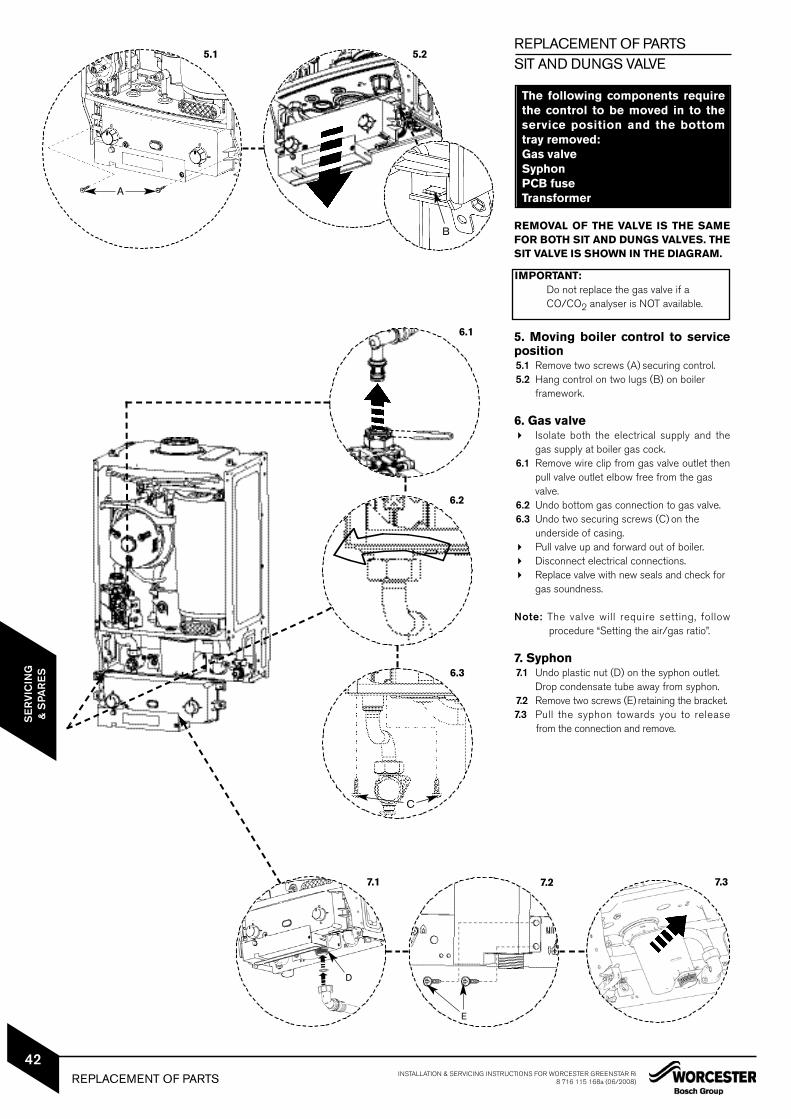
REPLACEMENT OF PARTSSIT AND DUNGS VALVE
REMOVAL OF THE VALVE IS THE SAMEFOR BOTH SIT AND DUNGS VALVES. THESIT VALVE IS SHOWN IN THE DIAGRAM.
5. Moving boiler control to serviceposition5.1 Remove two screws (A) securing control.5.2 Hang control on two lugs (B) on boiler
framework.
6. Gas valve Isolate both the electrical supply and the
gas supply at boiler gas cock.6.1 Remove wire clip from gas valve outlet then
pull valve outlet elbow free from the gas valve.
6.2 Undo bottom gas connection to gas valve.6.3 Undo two securing screws (C) on the
underside of casing. Pull valve up and forward out of boiler. Disconnect electrical connections. Replace valve with new seals and check for
gas soundness.
Note: The valve will require setting, followprocedure “Setting the air/gas ratio”.
7. Syphon7.1 Undo plastic nut (D) on the syphon outlet.
Drop condensate tube away from syphon.7.2 Remove two screws (E) retaining the bracket.7.3 Pull the syphon towards you to release
from the connection and remove.
D
The following components requirethe control to be moved in to theservice position and the bottomtray removed:Gas valveSyphonPCB fuseTransformer
5.1 5.2
A
6.2
6.3
7.37.27.1
B
E
C
6.1
REPLACEMENT OF PARTS INSTALLATION & SERVICING INSTRUCTIONS FOR WORCESTER GREENSTAR Ri8 716 115 168a (06/2008)
42
SE
RVI
CIN
G&
SPA
RE
S
IMPORTANT:Do not replace the gas valve if aCO/CO2 analyser is NOT available.
REPLACEMENT OF PARTS
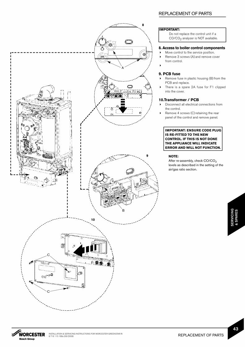
8. Access to boiler control components Move control to the service position. Remove 3 screws (A) and remove cover
from control.
9. PCB fuse Remove fuse in plastic housing (B) from the
PCB and replace. There is a spare 2A fuse for F1 clipped
into the cover.
10.Transformer / PCB Disconnect all electrical connections from
the control. Remove 4 screws (C) retaining the rear
panel of the control and remove panel.
IMPORTANT: ENSURE CODE PLUG IS RE-FITTED TO THE NEWCONTROL. IF THIS IS NOT DONETHE APPLIANCE WILL INDICATE ERROR AND WILL NOT FUNCTION.
NOTE:After re-assembly, check CO/CO2levels as described in the setting of theair/gas ratio section.
8
9
10
A
B
C
C
REPLACEMENT OF PARTSINSTALLATION & SERVICING INSTRUCTIONS FOR WORCESTER GREENSTAR Ri8 716 115 168a (06/2008)
43
SE
RVI
CIN
G&
SPA
RE
S
IMPORTANT:Do not replace the control unit if aCO/CO2 analyser is NOT available.
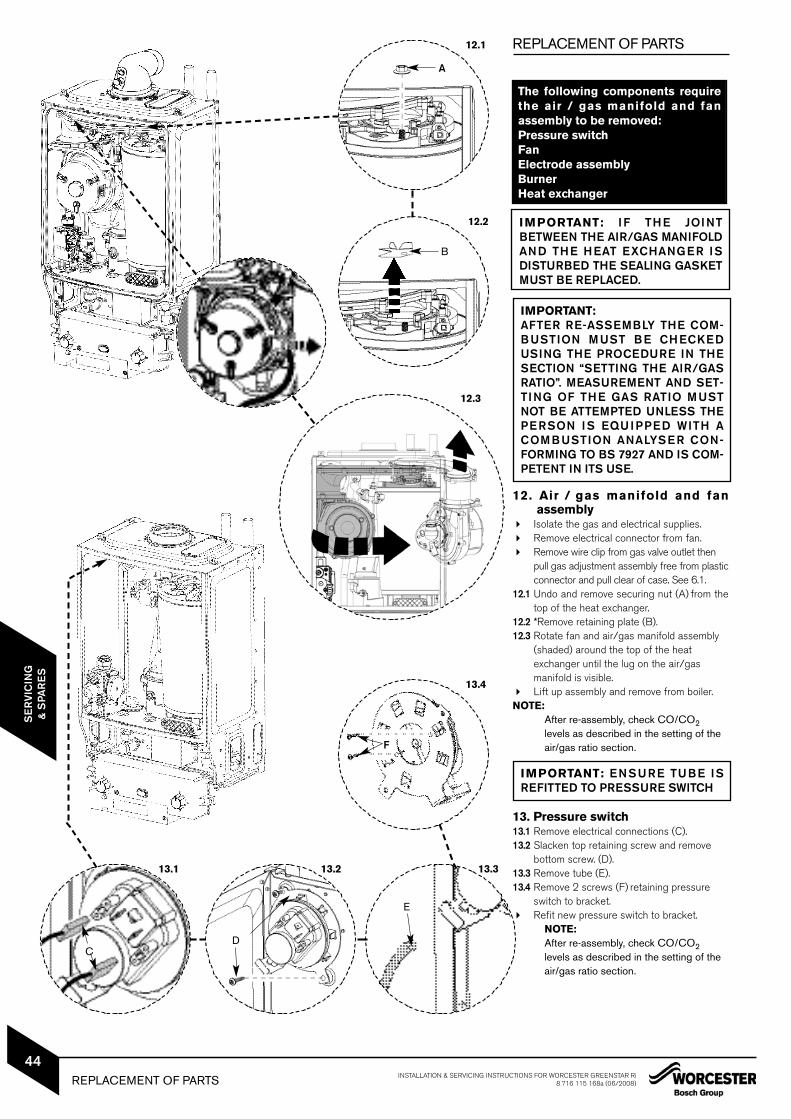
12. Air / gas manifold and fanassembly
Isolate the gas and electrical supplies. Remove electrical connector from fan. Remove wire clip from gas valve outlet then
pull gas adjustment assembly free from plasticconnector and pull clear of case. See 6.1.
12.1 Undo and remove securing nut (A) from thetop of the heat exchanger.
12.2 *Remove retaining plate (B).12.3 Rotate fan and air/gas manifold assembly
(shaded) around the top of the heat exchanger until the lug on the air/gas manifold is visible.
Lift up assembly and remove from boiler.NOTE:
After re-assembly, check CO/CO2levels as described in the setting of theair/gas ratio section.
13. Pressure switch13.1 Remove electrical connections (C).13.2 Slacken top retaining screw and remove
switch to bracket. Refit new pressure switch to bracket.
NOTE:After re-assembly, check CO/CO2levels as described in the setting of theair/gas ratio section.
REPLACEMENT OF PARTS
The following components requirethe air / gas manifold and fanassembly to be removed:Pressure switchFanElectrode assemblyBurnerHeat exchanger
12.1
12.2
13.4
13.313.213.1
A
B
CD
E
F
12.3
IMPORTANT: ENSURE TUBE ISREFITTED TO PRESSURE SWITCH
IMPORTANT: IF THE JOINTBETWEEN THE AIR/GAS MANIFOLDAND THE HEAT EXCHANGER ISDISTURBED THE SEALING GASKETMUST BE REPLACED.
IMPORTANT: AFTER RE-ASSEMBLY THE COM-BUSTION MUST BE CHECKEDUSING THE PROCEDURE IN THESECTION “SETTING THE AIR/GASRATIO”. MEASUREMENT AND SET-TING OF THE GAS RATIO MUSTNOT BE ATTEMPTED UNLESS THEPERSON IS EQUIPPED WITH ACOMBUSTION ANALYSER CON-FORMING TO BS 7927 AND IS COM-PETENT IN ITS USE.
REPLACEMENT OF PARTS INSTALLATION & SERVICING INSTRUCTIONS FOR WORCESTER GREENSTAR Ri8 716 115 168a (06/2008)
44
SE
RVI
CIN
G&
SPA
RE
S
REPLACEMENT OF PARTS
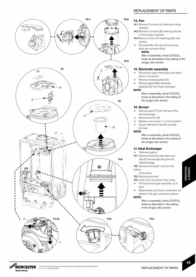
14. Fan14.1 Remove 3 screws (A) retaining mixing
chamber.14.2 Remove 2 screws (B) retaining the fan
to the air/gas manifold.14.3 Remove screw (C) retaining plate and
remove. Re-assemble with new fan ensuring
seals are correctly fitted.NOTE:After re-assembly, check CO/CO2levels as described in the setting of theair/gas ratio section.
15. Electrode assembly Disconnect spark electrodes and flame
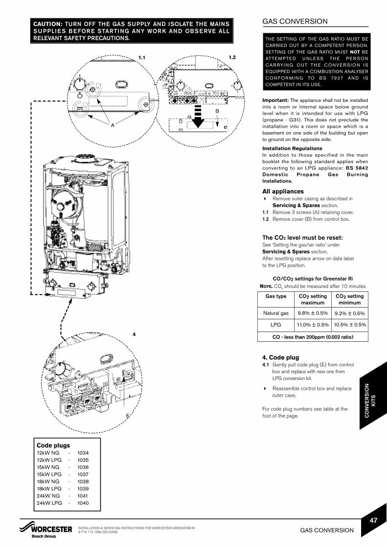
Important: The appliance shall not be installedinto a room or internal space below groundlevel when it is intended for use with LPG(propane - G31). This does not preclude theinstallation into a room or space which is abasement on one side of the building but opento ground on the opposite side.
Installation RegulationsIn addition to those specified in the mainbooklet the following standard applies whenconverting to an LPG appliance: BS 5842Domestic Propane Gas BurningInstallations.
All appliances Remove outer casing as described in
Servicing & Spares section.1.1 Remove 3 screws (A) retaining cover.1.2 Remove cover (B) from control box.
The CO2 level must be reset:See ‘Setting the gas/air ratio’ under Servicing & Spares section. After resetting replace arrow on data label to the LPG position.
4. Code plug4.1 Gently pull code plug (E) from control
box and replace with new one from LPG conversion kit.
Reassemble control box and replace outer case.
For code plug numbers see table at the foot of the page.
CAUTION: TURN OFF THE GAS SUPPLY AND ISOLATE THE MAINSSUPPLIES BEFORE STARTING ANY WORK AND OBSERVE ALLRELEVANT SAFETY PRECAUTIONS.
1.1
4
A
B
E
THE SETTING OF THE GAS RATIO MUST BECARRIED OUT BY A COMPETENT PERSON.SETTING OF THE GAS RATIO MUST NOT BEATTE M PTE D U N LE S S TH E P E R S O NC AR RYI N G O UT TH E C O NVE R S I O N I SEQUIPPED WITH A COMBUSTION ANALYSERC O N F O R M I N G TO B S 7927 AN D I SCOMPETENT IN ITS USE.
Code plugs12kW NG - 103412kW LPG - 103515kW NG - 103615kW LPG - 103718kW NG - 103818kW LPG - 103924kW NG - 104124kW LPG - 1040
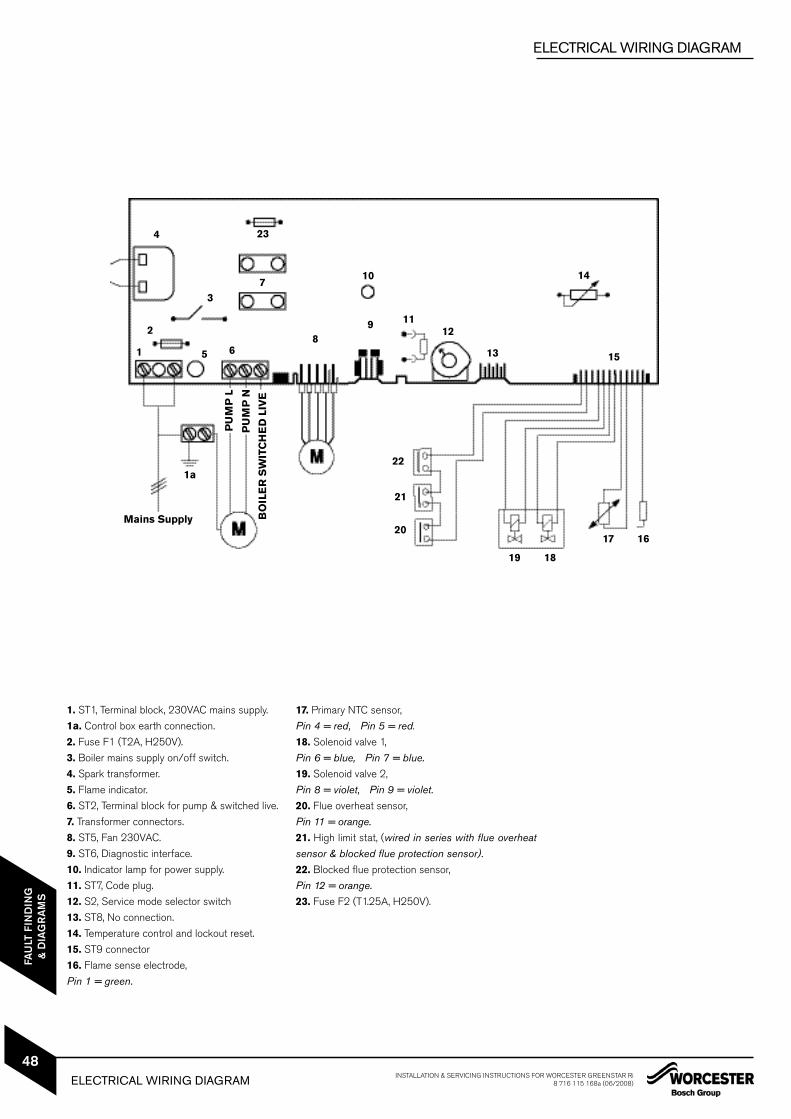
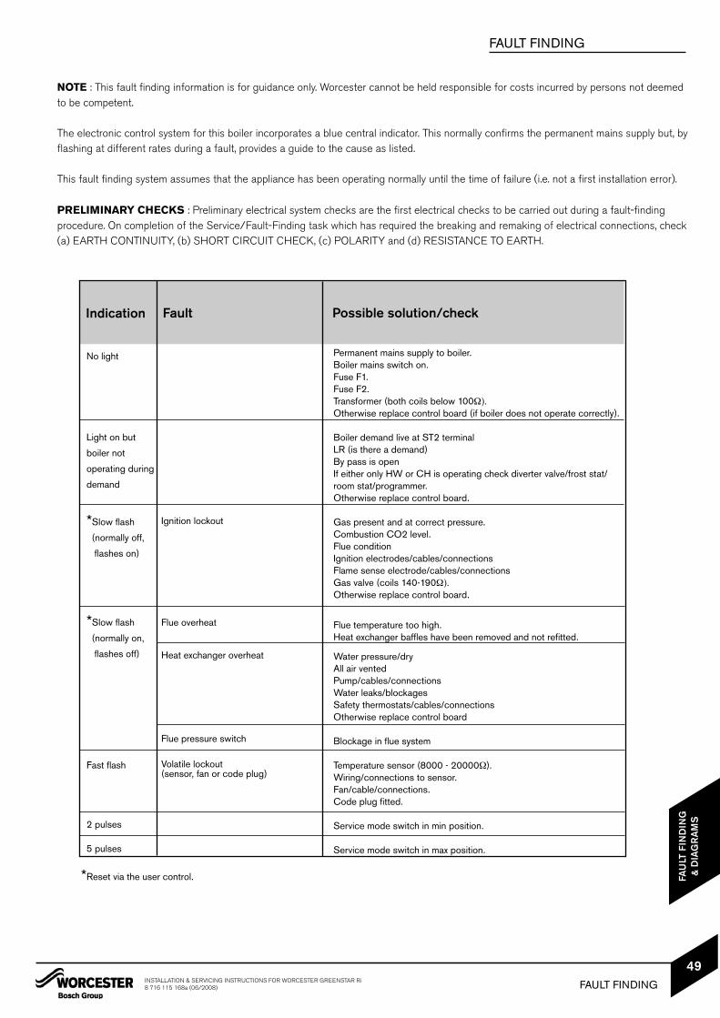
Permanent mains supply to boiler.Boiler mains switch on.Fuse F1.Fuse F2.Transformer (both coils below 100Ω).Otherwise replace control board (if boiler does not operate correctly).
Boiler demand live at ST2 terminalLR (is there a demand)By pass is openIf either only HW or CH is operating check diverter valve/frost stat/room stat/programmer.Otherwise replace control board.
Gas present and at correct pressure.Combustion CO2 level.Flue conditionIgnition electrodes/cables/connectionsFlame sense electrode/cables/connectionsGas valve (coils 140-190Ω).Otherwise replace control board.
Flue temperature too high.Heat exchanger baffles have been removed and not refitted.
Water pressure/dryAll air ventedPump/cables/connectionsWater leaks/blockagesSafety thermostats/cables/connectionsOtherwise replace control board
Blockage in flue system
Temperature sensor (8000 - 20000Ω).Wiring/connections to sensor.Fan/cable/connections.Code plug fitted.
Service mode switch in min position.
Service mode switch in max position.
NOTE : This fault finding information is for guidance only. Worcester cannot be held responsible for costs incurred by persons not deemedto be competent.
The electronic control system for this boiler incorporates a blue central indicator. This normally confirms the permanent mains supply but, byflashing at different rates during a fault, provides a guide to the cause as listed.
This fault finding system assumes that the appliance has been operating normally until the time of failure (i.e. not a first installation error).
PRELIMINARY CHECKS : Preliminary electrical system checks are the first electrical checks to be carried out during a fault-findingprocedure. On completion of the Service/Fault-Finding task which has required the breaking and remaking of electrical connections, check (a) EARTH CONTINUITY, (b) SHORT CIRCUIT CHECK, (c) POLARITY and (d) RESISTANCE TO EARTH.
MAIN FUNCTIONINSTALLATION & SERVICING INSTRUCTIONS FOR WORCESTER GREENSTAR Ri
8 716 115 168a (06/2008)51
50
FAU
LT F
IND
ING
& D
IAG
RA
MS
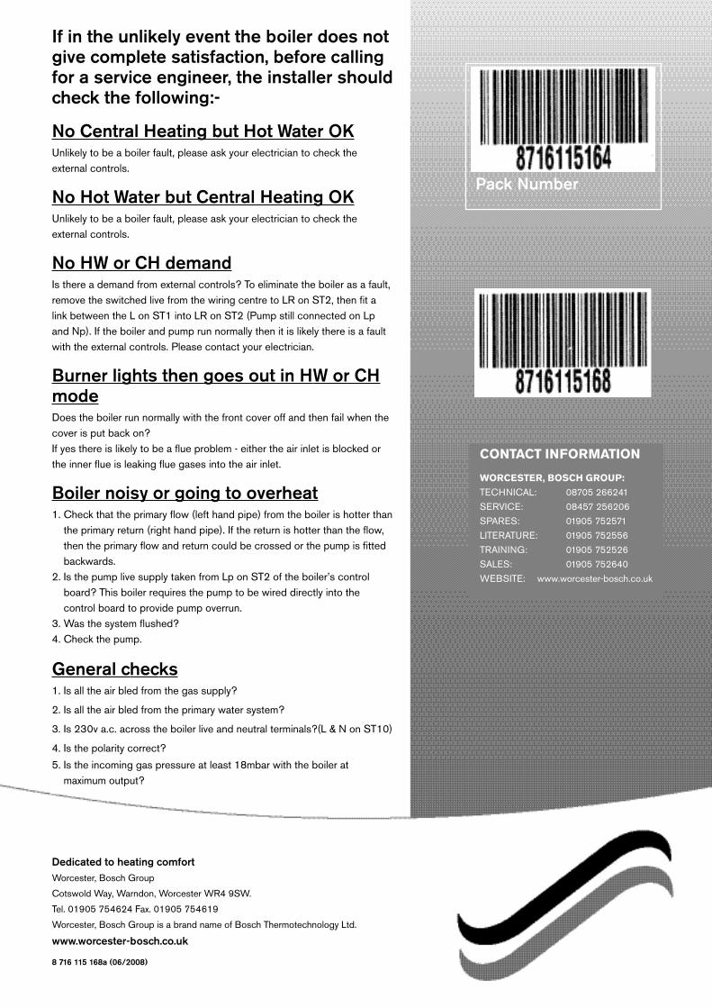
If in the unlikely event the boiler does notgive complete satisfaction, before callingfor a service engineer, the installer shouldcheck the following:-
No Central Heating but Hot Water OKUnlikely to be a boiler fault, please ask your electrician to check theexternal controls.
No Hot Water but Central Heating OKUnlikely to be a boiler fault, please ask your electrician to check theexternal controls.
No HW or CH demandIs there a demand from external controls? To eliminate the boiler as a fault,remove the switched live from the wiring centre to LR on ST2, then fit alink between the L on ST1 into LR on ST2 (Pump still connected on Lpand Np). If the boiler and pump run normally then it is likely there is a faultwith the external controls. Please contact your electrician.
Burner lights then goes out in HW or CHmodeDoes the boiler run normally with the front cover off and then fail when thecover is put back on? If yes there is likely to be a flue problem - either the air inlet is blocked orthe inner flue is leaking flue gases into the air inlet.
Boiler noisy or going to overheat1. Check that the primary flow (left hand pipe) from the boiler is hotter than
the primary return (right hand pipe). If the return is hotter than the flow,then the primary flow and return could be crossed or the pump is fittedbackwards.
2. Is the pump live supply taken from Lp on ST2 of the boiler’s controlboard? This boiler requires the pump to be wired directly into the control board to provide pump overrun.
3. Was the system flushed?4. Check the pump.
General checks1. Is all the air bled from the gas supply?
2. Is all the air bled from the primary water system?
3. Is 230v a.c. across the boiler live and neutral terminals?(L & N on ST10)
4. Is the polarity correct?
5. Is the incoming gas pressure at least 18mbar with the boiler at maximum output?
Dedicated to heating comfortWorcester, Bosch Group
Cotswold Way, Warndon, Worcester WR4 9SW.
Tel. 01905 754624 Fax. 01905 754619
Worcester, Bosch Group is a brand name of Bosch Thermotechnology Ltd.