IF YOU HAVE ANY QUESTIONS OR COMMENTS ABOUT THIS OR ANY DeWALT TOOL, CALL US TOLL FREE AT: 1-800-4-DeWalt (1-800-433-9258).
Safety
WARNING: To reduce the risk of injury, read the safety manual provided with your product or access it online at www.DeWALT.com.Use of controls or adjustments or performance of procedures other than those specified herein may result in hazardous radiation exposure
WarnIng labels For your convenience and safety, the following label is on your laser.
CAUTION: LASER RADIATION - DO NOT STARE INTO BEAM. CLASS 2 LASER PRODUCT.
Laser InformationThe DW0811 laser level is a class 2 laser product and complies with 21 CFR 1040.10 and
1040.11 except for deviations pursuant to laser notice No. 50, dated June 24, 2007.
Product OverviewThe DW0811 laser level is a self-leveling laser tool that can be used for horizontal (level) and vertical (plumb) alignment and square alignment. This tool comes fully assembled and has been designed with features that allow for quick and easy set-up. Please read and understand all instructions within this instruction manual in addition to the Safety Manual prior to use.
SpecificationssPecIFIcatIons
Light Source Semiconductor laser diode
Laser Wavelength 630–680 nm visible
Laser Power <1.0 mW (each beam) CLASS 1 LASER PRODUCT
Working Range ±100' (30 m) with detector
Accuracy* (Vertical) ± 5/32" @ 30' (±4 mm @ 10 m)
Accuracy* (Level) ± 5/32" @ 30' (±4 mm @ 10 m)
Indicators Flashing Indicator: battery lowFlashing Laser: tilt range exceeded
Power Source 3 AA size batteries (4.5V DC)
Operating Temperature 20 °F to 120 °F (-10 °C to 50 °C)
Storage Temperature -5 °F to 140 °F (-20 °C to 60 °C)
Environmental IP54
Keypad, Modes and LED.Power switch.The Power ON/OFF switch is located on the rear of the tool as shown in figure 1. When the switch (C) is in the OFF/LOCKED position, the unit will remain off and the pendulum will be lockedWhen the on/off switch (C) is in the ON/UNLOCKED position, the unit will be powered ON and the pendulum will be released from the locked position and self level.
Keypad.The keypad located on the top of the tool provides activation keys for selection of laser dots and / or line function.
Low Battery Indicator.The DW0811 is equipped with a low battery indicator on the keypad as shown in Figure 2. The indicator light is located on the keypad. When the light flashes, the batteries are low and need to be replaced. The laser may continue to operate for a short time while the batteries continue to drain. After fresh batteries are installed and the laser is turned on again, the indicator light will remian green.
Out of Tilt Range IndicatorThe DW0811 is equipped with an out of tilt indicator on the keypad as shown in Figure 2. Whenthe tilt range (> 4° tilt) has been exceeded the LED will will turn on and the laser beam will flash. The flashing beam indicates the tilt range has been exceeded and the tool IS NOT LEVEL (OR PLUMB) AND SHOULD NOT BE USED FOR DETERMINING OR MARKING LEVEL (OR PLUMB). Try repositioning the laser on a more level surface.
Batteries & PowerYour laser tool requires 3 x AA batteries. (E)Use only new, high-quality batteries for best results.• Ensure batteries are in good working condition. If the low battery indicator light is flashing, the
batteries need replacement.• To extend battery life, turn laser off when not working with or marking the beam.
Set UplevelIng the laserThis tool is self-leveling. It is calibrated at the factory to find plumb as long as it is positioned on flat surface within 4° of level. As long as the tool is properly calibrated, no manual adjustments must be made.
To ensure the accuracy of your work, check to make sure your laser is calibrated often. See Field Calibration Check.
• Before attempting to use the laser,make sure it is positioned securely, on a smooth, flatsurface.
OPEratIOnturning the Laser On and Off (Fig. 6)• With the laseroff,place itonastable, flatsurface.Turn the laseronbysliding theon/off
switch (A) to the ON/UNLOCKED position. • Activate or deactivate the desired function using the keypad (B) located on the side of the
tool. It can project 360° horizontal line (C) and a vertical line (D) • To turn the laser off, slide the the on/off switch (A) to the locked position.
The DW0811 is equipped with a locking pendulum mechanism. This feature is only activated when the laser is switched off.
Using the LaserThe beams are level or plumb as long as the calibration has been checked (see Field Calibration Check) and the laser beam is not flashing (see Out of Tilt Range Indicator).The tool can be used to transfer points using any combination of the five beams and/or horizontal line.
usIng the laser WIth accessorIesThe laser is equipped with both 1/4" x 20 and 5/8" x11 female threads on the bottom of the unit. These threads may be used to accommodate current or future DeWALT accessories. Only use DeWALT accessories specified for use with this product. Follow the directions included with the accessory.
WARNING: Since accessories, other than those offered by DeWAlt, have not been tested with this product, use of such accessories with this tool could be hazardous. To reduce the risk of injury, only DeWAlt recommended accessories should be used with this product. Recommended accessories for use with your tool are available at extra cost from your local dealer or authorized service center. If you need assistance in locating any accessory, please contact DeWALT Industrial Tool Co., 701 East Joppa Road, Baltimore, MD 21286, call 1-800-4-DeWALT (1-800-433-9258) or visit our website: www.DeWALT.com.
Field Calibration Check
Levelling Accuracy(See Figure 1)Calibration check should be performed using a distance no shorter than the distance of the applications for which the tool will be used.
If y
ou h
ave
qu
esti
ons
or c
omm
ents
, con
tact
us.
1-8
00-4
-DeW
ALT
• w
ww
.dew
alt
.com
Page 2
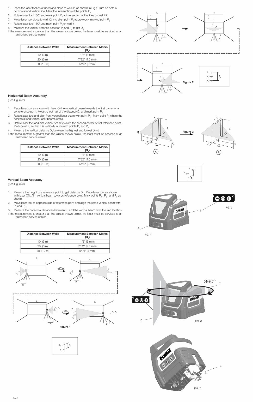
1. Place the laser tool on a tripod and close to wall #1 as shown in Fig 1. Turn on both a horizontal and vertical line. Mark the intersection of the points P1.
2. Rotate laser tool 180° and mark point P2 at intersection of the lines on wall #2 3. Move laser tool close to wall #2 and align point P3 at previously marked point P2
4. Rotate laser tool 180° and mark point P4 on wall #15. Measure the vertical distance between P1 and P4 to get D3. If the measurement is greater than the values shown below, the laser must be serviced at an
authorized service center
Distance between Walls Measurement between Marks (D3)
10' (3 m) 1/8" (3 mm)
20' (6 m) 7/32" (5.5 mm)
30' (10 m) 5/16" (8 mm)
Horizontal Beam Accuracy(See Figure 2)
1. Place laser tool as shown with laser ON. Aim vertical beam towards the first corner or a set reference point. Measure out half of the distance D1 and mark point P1 .
2. Rotate laser tool and align front vertical laser beam with point P1 . Mark point P2 where the horizontal and vertical laser beams cross.
3. Rotate laser tool and aim vertical beam towards the second corner or set reference point. Mark point P3 so that it is vertically in line with points P1 and P2 .
4. Measure the vertical distance D2 between the highest and lowest point.If the measurement is greater than the values shown below, the laser must be serviced at an
authorized service center.
Distance between Walls Measurement between Marks (D3)
10' (3 m) 1/8" (3 mm)
20' (6 m) 7/32" (5.5 mm)
30' (10 m) 5/16" (8 mm)
Vertical Beam Accuracy(See Figure 3)
1. Measure the height of a reference point to get distance D1 . Place laser tool as shown with laser ON. Aim vertical beam towards reference point. Mark points P1 , P2 , and P3 as shown.
2. Move laser tool to opposite side of reference point and align the same vertical beam with P2 and P3 .
3. Measure the horizontal distances between P1 and the vertical beam from the 2nd location.If the measurement is greater than the values shown below, the laser must be serviced at an
authorized service center.
Distance between Walls Measurement between Marks (D3)
SI TIENE CONSULTAS O COMENTARIOS ACERCA DE ESTA HERRAMIENTA DeWALT O DE CUALQUIER OTRA, LLÁMENOS SIN CARGO AL NÚMERO: 1-800-4-DeWalt (1-800-433-9258).
Seguridad
ADVERTENCIA:Parareducirelriesgodelesiones,leaelmanualdeseguridadprovistocon su producto o acceda al mismo en línea en www.DeWALT.com.Elusodecontrolesoajustesolarealizacióndeprocedimientosdiferentesalosespecificadosenelpresentepuederesultarenexposiciónpeligrosaalaradiación
etIquetas De aDvertencIa Para su comodidad y seguridad, se incluye la etiqueta siguiente en su láser.
PRECAUCIÓN: RADIACIÓN LÁSER - NO MIRE FIJO EL RAYO. PRODUCTO LÁSER DE CLASE 2.
Información sobre el láserEl nivel láser DW0811 es un producto láser de clase 2 y cumple con 21 CFR 1040.10 y 1040.11
excepto por las desviaciones en virtud de la notificación para láser N.° 50, de fecha 24 de junio de 2007.
Descripción del productoEl nivel láser DW0811 es una herramienta láser de autonivelación que puede usarse para alineación horizontal (nivel) y vertical (plomada) y alineación cuadrada. Esta herramienta viene totalmente ensamblada y ha sido diseñada con características que permiten una instalación rápida y sencilla. Lea y comprenda todas las instrucciones en este manual de instrucciones además del Manual de seguridad antes del uso.
Precisión* (vertical) ±4 mm a 10 m (± 5/32" a 30')
Precisión* (nivel) ±4 mm a 10 m (± 5/32" a 30')
indicadores Indicador destellando: batería baja Láser destellando: rango de inclinación excedido
Fuente de alimentación 3 baterías tamaño AA (4,5 VCC)
Temperatura de funcionamiento
-10 °C a 50 °C (20 °F a 120 °F)
Temperatura de almacenamiento
-20 °C a 60 °C (-5 °F a 140 °F)
Ambiental IP54
teclado, Modos y LED.Interruptor de energía.El interruptor de ENCENDIDO/APAGADO se ubica cerca de la parte posterior de la herramienta como se muestra en la figura 1. Cuando el interruptor (C) está en la posición APAGADO/BLOQUEADO, la unidad se mantendrá apagada y el péndulo se bloqueará Cuando el interruptor de encendido/apagado (C) está en la posición ENCENDIDO/DESBLOQUEADO, la unidad se encenderá y el péndulo se liberará de la posición de bloqueo y se autonivelará.
Teclado.El teclado ubicado en la parte superior de la herramienta contiene las teclas de activación para la selección de los puntos láser o la función de línea.
Indicador de batería baja.El DW0811 está equipado con un indicador de batería baja en el teclado como se muestra en la Figura 2. La luz del indicador se ubica en el teclado. Cuando la luz parpadea, las baterías están bajas y deben reemplazarse. El láser puede continuar operando por un tiempo breve hasta que las baterías se agoten por completo. Una vez que se instalen las baterías nuevas y el láser se encienda nuevamente, la luz del indicador se mantendrá verde.
Indicador de fuera de rango de inclinaciónEl DW0811 está equipado con un indicador fuera de rango en el teclado como se muestra en la Figura 2. Cuando el rango de inclinación (inclinación > 4°) se ha excedido, el LED se encenderá y el rayo láser parpadeará. El rayo parpadeante indica que se ha excedido el rango de inclinación y que la herramienta NO ESTÁ A NIVEL (O PLOMADA) Y NO DEBE USARSE PARA DETERMINAR O MARCAR EL NIVEL (O PLOMADA). Intente cambiar la posición del láser en una superficie más nivelada.
Baterías y alimentaciónSu herramienta láser requiere 3 baterías AA. (E)Use solo baterías nuevas de alta calidad para obtener mejores resultados.• Verifique que las baterías estén en buenas condiciones. Si la luz del indicador de batería baja
parpadea, debe reemplazar las baterías.• Para extender la duración de las baterías, apague el láser cuando no trabaja o marca el rayo.
InstalaciónnIvelacIón Del láserEsta herramienta posee autonivelación. Está calibrada en fábrica para encontrar plomada cuando se coloca en una superficie plana dentro de 4° del nivel. Si la herramienta está calibrada correctamente, no deben realizarse ajustes manuales.
Paraasegurarlaprecisióndesutrabajo,confrecuenciacompruebequesuláserestécalibrado.Vea Comprobación de calibración en campo.
• Antesdeintentarusarelláser,asegúresedequeestécolocadofirmementeenunasuperficiesuave y plana.
• Siempremarqueelcentrodelpuntoopatróncreadoporelláser.• los cambios extremos de temperatura pueden causar el movimiento de partes internas
que pueden afectar la precisión. Compruebe la precisión con frecuencia al trabajar. VeaComprobación de calibración en campo.
• Siel lásersehacaído,compruebequeestécalibrado.VeaComprobación de calibración en campo.
FUnCIOnaMIEntOEncendido y apagado del láser (Fig. 6)• Con el láser apagado, colóquelo en una superficie estable y plana. Encienda el
láser deslizando el interruptor de encendido/apagado (A) a la posición ENCENDIDO/DESBLOQUEADO.
• Active o desactive la función deseada usando el teclado (B) ubicado en el lateral de la herramienta. Puede proyectar una línea horizontal (C) y una línea vertical (D) de 360°
• Apague el láser deslizando el interruptor de encendido/apagado (A) a la posición de bloqueo.
El DW0811 está equipado con un mecanismo de péndulo de bloqueo. Esta función solo se activa cuando el láser se apaga.
Uso del láserLos rayos están a nivel o en plomada si se ha comprobado la calibración (vea Comprobación de calibración en campo) y el rayo láser no parpadee (vea Indicador de fuera de rango de inclinación).La herramienta puede usarse para transferir puntos usando cualquier combinación de los cinco rayos y/o líneas horizontales.
uso Del láser con accesorIosEl láser está equipado con roscas hembra de 1/4" x 20 y 5/8" x 11 en la parte inferior de la unidad. Estas roscas pueden usarse para alojar accesorios actuales o futuros de DeWALT. Use solo accesorios DeWALT especificados para usar con este producto. Siga las instrucciones incluidas con el accesorio.
ADVERTENCIA: Como los accesorios, fuera de los ofrecidos por DeWAlt, no han sido probadosconesteproducto,elusodetalesaccesoriosconestaherramientapodríaserpeligroso.Para reducir el riesgode lesiones, solodebeusaraccesorios recomendadosporDeWAlt con este producto.Los accesorios recomendados para usar con su herramienta están disponibles a un costo adicional con su distribuidor local o centro de servicio autorizado. Si necesita asistencia para ubicar un accesorio, contacte a DeWALT Industrial Tool Co., 701 East Joppa Road, Baltimore, MD 21286, llame al 1-800-4-DeWALT (1-800-433-9258) o visite nuestro sitio web: www.DeWALT.com.
Comprobación de calibración en campoPrecisión de la nivelación(Vea la Figura 1 )La comprobación de calibración debe realizarse usando una distancia no menor a la distancia de las aplicaciones para las que se usará la herramienta.
Si t
ien
e p
reg
un
tas
o co
men
tari
os, p
ued
e co
nta
ctar
nos
.
1-8
00-4
-DeW
ALT
• w
ww
.dew
alt
.com
Page 4
1. Coloque la herramienta láser en un trípode y cerca de la pared N.° 1 como se muestra en la Fig. 1. Encienda una línea horizontal y vertical. Marque la intersección de los puntos P1.
2. Rote la herramienta láser 180° y marque el punto P2 en la intersección de las líneas en la pared N.° 2
3. Mueva la herramienta láser cerca de la pared N.° 2 y alinee el punto P3 en el punto marcado anteriormente P2
4. Gire la herramienta láser 180° y marque el punto P4 en la pared N.° 15. Mida la distancia vertical entre P1 y P4 para obtener D3.Si la medición es mayor a los valores que se indican a continuación, el láser debe ser reparado
en un centro de servicio autorizado.
Distancia entre las paredes Medición entre las marcas (D3)
3 m (10') 3 mm (1/8")
6 m (20') 5,5 mm (7/32")
10 m (30') 8 mm (5/16")
Precisión del rayo horizontal(Vea la Figura 2)
1. Coloque la herramienta láser como se muestra con el láser ENCENDIDO. Apunte el rayo vertical hacia la primera esquina o hacia un punto de referencia definido. Mida la mitad de la distancia D1 y marque el punto P1.
2. Gire la herramienta láser y alinee el rayo láser vertical delantero con el punto P1. Marque el punto P2 donde se cruza el rayo láser horizontal y vertical.
3. Gire la herramienta láser y apunte el rayo vertical hacia la segunda esquina o punto de referencia definido. Marque el punto P3 de tal forma que esté verticalmente en línea con los puntos P1 y P2.
4. Mida la distancia vertical D2 entre el punto más alto y más bajo.Si la medición es mayor a los valores que se indican a continuación, el láser debe ser reparado
en un centro de servicio autorizado.
Distancia entre las paredes Medición entre las marcas (D3)
3 m (10') 3 mm (1/8")
6 m (20') 5,5 mm (7/32")
10 m (30') 8 mm (5/16")
Precisión del rayo vertical(Vea la Figura 3)
1. Mida la altura de un punto de referencia para obtener la distancia D1. Coloque la herramienta láser como se muestra con el láser ENCENDIDO. Apunte el rayo vertical hacia el punto de referencia. Marque los puntos P1 , P2 y P3 como se muestra.
2. Mueva la herramienta láser al lado opuesto del punto de referencia y alinee el mismo rayo vertical con P2 y P3.
3. Mida las distancias horizontales entre P1 y el rayo vertical de la segunda ubicación.Si la medición es mayor a los valores que se indican a continuación, el láser debe ser reparado
en un centro de servicio autorizado.
Distancia entre las paredes Medición entre las marcas (D3)
POUR TOUTE QUESTION OU TOUT COMMENTAIRE AU SUJET DE CET OUTIL OU DE TOUT AUTRE OUTIL DeWALT, APPELER SANS FRAIS AU NUMÉRO : 1 800 4-DeWalt (1 800 433-9258).
ÉtIquettes D'avertIsseMent Pour des raisons pratiques et de sécurité, l'étiquette suivante a été apposée sur le laser.
ATTENTION : RAYONNEMENT LASER - NE JAMAIS FIXER LE FAISCEAUÉqUIPEMENT LASER DE CATÉGORIE 2
renseignements sur le laserLe niveau au laser DW0811 est un laser de catégorie 2 conforme aux normes 21 CFR 1040.10
et 1040.11 à l'exception des dérogations prévues par l'avis nº 50 en date du 24 juin 2007.
aperçu du produitLe niveau au laser DW0811 est un outil laser autonivelant pouvant être utilisé pour un alignement horizontal (niveau), vertical (aplomb) et d'angle droit. Complètement assemblé, il comporte des fonctions permettant un réglage rapide et facile. Avant de l'utiliser, veuillez lire et comprendre toutes les consignes de ce manuel d'instructions ainsi que le guide de sécurité.
Précision* (à la verticale) ± 4 mm à 9 m (5/32 po à 30 pi)
Précision* (niveau) ± 4 mm à 9 m (5/32 po à 30 pi)
Voyants Voyant clignotant : pile faible Laser clignotant : dépassement de la plage d'inclinaison
Source d'alimentation 3 piles AA (4,5 V c.c.)
Température d'utilisation De -10 °C à 50 °C (20 °F à 120 °F)
Température d'entreposage De -20 °C à 60 °C (-5 °F à 140 °F)
Environnement IP54
Clavier, modes et voyant à DELInterrupteur d'alimentationL'interrupteur Marche/Arrêt se trouve au dos de l'outil, comme illustré à la figure 1. Lorsque l'interrupteur (C) est en position ARRÊT/BLOQUÉ, l'appareil est éteint et le pendule est bloqué. Lorsque l'interrupteur Marche/Arrêt (C) est en position MARCHE/DÉBLOQUÉ, l'appareil est allumé, le pendule et débloqué et la fonction d'autonivelage est active.
ClavierLe clavier situé au-dessus de l'outil comporte des touches d'activation permettant de choisir entre les fonctions de points ou de ligne laser.
Voyant de pile faibleL'appareil DW0811 est doté d'un voyant de pile faible, comme illustré à la figure 2. Ce voyant est situé sur le clavier. Lorsqu'il clignote, les piles sont faibles et doivent être remplacées. Le laser continuera à fonctionner quelque temps pendant que les piles se déchargent. Une fois les piles neuves installées et le laser rallumé, le voyant reste vert.
Voyant d'erreur d'inclinaisonL'appareil DW0811 est doté d'un voyant d'erreur d'inclinaison situé sur le clavier, comme illustré à la figure 2. Lorsque la plage d'inclinaison (inclinaison > 4°) est dépassée, le voyant s'allume et clignote et le faisceau laser se met à clignoter. Le clignotement du faisceau laser indique que la plage d'inclinaison a été dépassée et que l'outil N'EST PAS DE NIVEAU (OU D'APLOMB) ET NE DOIT PAS SERVIR À DÉTERMINER OU À MARQUER LE NIVEAU (OU L'APLOMB). Essayer de repositionner le laser sur une surface plus à niveau.
Piles et alimentationVotre outil laser a besoin de 3 piles AA. (E)Pour obtenir de meilleurs résultats, n'utiliser que des piles neuves de qualité supérieure.• Vérifier qu'elles sont en bon état. Lorsque le voyant de pile faible clignote, il faut remplacer
les piles.• Pour prolonger les piles, éteindre le laser lorsque vous ne l'utilisez pas ou que vous marquez
le faisceau.
réglageMIse à nIveau Du laserCet outil est autonivelant. Il est étalonné en usine pour trouver l'aplomb à condition d'être posé sur une surface plane d'une inclinaison maximale de 4°. Tant qu'il est bien étalonné, il n'est pas nécessaire de le régler manuellement.
Pouruntravailprécis,veilleràétalonnervotrelaserfréquemment.VoirVérification de l'étalonnage sur place.
internesetcompromettrelaprécision.Aucoursdutravail,vérifierfréquemmentlaprécision.VoirVérification de l'étalonnage sur place.
• Si le laser est tombé, vérifier qu'il est toujours étalonné. VoirVérification de l'étalonnage sur place.
FOnCtIOnnEMEntMarche et arrêt du laser (fig. 6)• Placer le laser éteint sur une surface plane et stable. L'allumer en glissant l'interrupteur
Marche/Arrêt (A) en position MARCHE/DÉBLOQUÉ. • Activer ou désactiver la fonction souhaitée à l'aide du clavier (B) situé sur le côté de l'outil. Il
peut projeter une ligne horizontale à 360° (C) et une ligne verticale (D)• Pour éteindre le laser, glisser l'interrupteur Marche/Arrêt (A) en position de blocage.
Le modèle DW0811 est équipé d'un mécanisme de blocage à mouvements de pendule. Cette fonction ne s'active que lorsque l'on éteint le laser.
Utilisation du laserLes faisceaux seront de niveau ou d'aplomb si l'étalonnage a été vérifié (voir Vérification de l'étalonnage sur place) et si le faisceau laser ne clignote pas (voir Voyant d'erreur d'inclinaison).Il est possible d'utiliser l'outil pour reporter des points à l'aide d'une combinaison des cinq faisceaux et de la ligne horizontale.
utIlIsatIon Du laser avec accessoIresDes filets de vis femelles de 6,35 mm (1/4 po) x 20 et 15,8 (5/8 po) x 11 se trouvent sous l'appareil. Ils servent à fixer des accessoires DeWALT existants ou futurs. N'utiliser que les accessoires DeWALT conçus pour ce produit. Respecter les consignes fournies avec l'accessoire.
AVERTISSEMENT : Étantdonnéqu'aucuntestn'aétéfaitavecdesaccessoiresnonvenduspar DeWAlt,leurutilisationaveccetoutilpourraits'avérerdangereuse.Pourréduirelesrisquesdeblessure,n'utiliserquelesaccessoiresrecommandésparDeWAlt.Les accessoires recommandés pour l'utilisation avec cet outil sont en vente chez un détaillant local ou un centre de service autorisé. Si vous avez besoin d'aide pour trouver un accessoire, communiquer avec DeWALT Industrial Tool Co., 701 East Joppa Road, Baltimore, MD 21286, composer le 1 800 4-DeWALT (1 800 433-9258) ou consulter notre site Web : www.DeWALT.com.
Vérification de l'étalonnage sur place
Précision du nivellement(Voir la figure 1)Il est important de vérifier l'étalonnage sur une distance au moins équivalente à celle de l'installation pour laquelle le laser sera utilisé.
Pou
r to
ute
qu
esti
on o
u t
out
com
men
tair
e, c
omm
un
iqu
er a
vec
nou
s.
1 8
00 4
-DeW
ALT
• w
ww
.dew
alt
.com
Page 6
1. Placer l'outil laser sur un trépied proche du mur 1, comme illustré à la figure 1. Projeter une ligne horizontale et une ligne verticale. Marquer l'intersection des points P1.
2. Faire pivoter l'outil laser à 180° et marquer le point P2 à l'intersection des lignes sur le mur 2.
3. Placer l'outil laser près du mur 2 et aligner le point P3 sur le point P2 marqué plus tôt.4. Faire pivoter l'outil laser à 180° et marquer le point P4 sur le mur 1.5. Mesurer la distance verticale entre P1 et P4 pour obtenir D3.Si la mesure est supérieure aux valeurs indiquées ci-dessous, le laser doit être réparé dans un
centre de service autorisé.
Distance entre les murs Mesure entre les marques (D3)
3 m (10 pi) 3 mm (1/8 po)
6 m (20 pi) 5,5 mm (7/32 po)
9 m (30 pi) 8 mm (5/16 po)
Précision du faisceau horizontal(Voir la figure 2)
1. Placer l'appareil laser comme illustré. Le laser doit être allumé. Diriger le faisceau vertical vers le premier angle ou un point de référence établi. Mesurer la moitié de la distance D1 et marquer le point P1.
2. Faire pivoter l'outil laser et aligner le faisceau laser vertical frontal sur le point P1. Marquer le point P2 où se croisent les faisceaux laser horizontal et vertical.
3. Faire pivoter l'outil laser et diriger le faisceau vertical vers le deuxième angle ou point de référence établi. Marquer le point P3 de manière à ce qu'il soit verticalement aligné avec les points P1 et P2.
4. Mesurer la distance verticale D2 entre le point le plus haut et le point le plus bas.Si la mesure est supérieure aux valeurs indiquées ci-dessous, le laser doit être réparé dans un
centre de service autorisé.
Distance entre les murs Mesure entre les marques (D3)
3 m (10 pi) 3 mm (1/8 po)
6 m (20 pi) 5,5 mm (7/32 po)
9 m (30 pi) 8 mm (5/16 po)
Précision du faisceau vertical(Voir la figure 3)
1. Mesurer la hauteur d'un point de référence pour obtenir la distance D1. Placer l'appareil laser comme illustré. Le laser doit être allumé. Diriger le faisceau vertical vers un point de référence. Marquer les points P1, P2 et P3 comme illustré.
2. Placer l'outil laser à l'autre extrémité du point de référence et aligner le même faisceau vertical avec P2 et P3.
3. Depuis le deuxième emplacement, mesurer les distances horizontales entre P1 et le faisceau vertical.
Si la mesure est supérieure aux valeurs indiquées ci-dessous, le laser doit être réparé dans un centre de service autorisé.
Distance entre les murs Mesure entre les marques (D3)