97
© 2011 Cisco and/or its affiliates. All rights reserved. Cisco Public BRKCRS-2041 1 BRKCRS-2041 WAN Architectures and Design Principles
© 2011 Cisco and/or its affiliates. All rights reserved. Cisco PublicBRKCRS-2041 1
BRKCRS-2041
WAN Architectures and Design Principles
© 2011 Cisco and/or its affiliates. All rights reserved. Cisco PublicBRKCRS-2041 2
Agenda
WAN Technologies & Solutions
–WAN Transport Technologies
–WAN Overlay Technologies
–WAN Optimisation
–Wide Area Network Quality of Service
WAN Architecture Design Considerations
–Secure WAN Communication with GETVPN
–Internet Backup Connectivity with DMVPN
–WCCP Implementation Consideration
© 2011 Cisco and/or its affiliates. All rights reserved. Cisco PublicBRKCRS-2041 3
WAN Transport Technologies

© 2011 Cisco and/or its affiliates. All rights reserved. Cisco PublicBRKCRS-2041 4
Hierarchical Network Design
Core
Distribution
Access
Data Centre/HQ
Regionalhub
SpokeSite 1
SpokeSite N
...
Regionalhub
SpokeSite 1’
SpokeSite N’
...
© 2011 Cisco and/or its affiliates. All rights reserved. Cisco PublicBRKCRS-2041 5
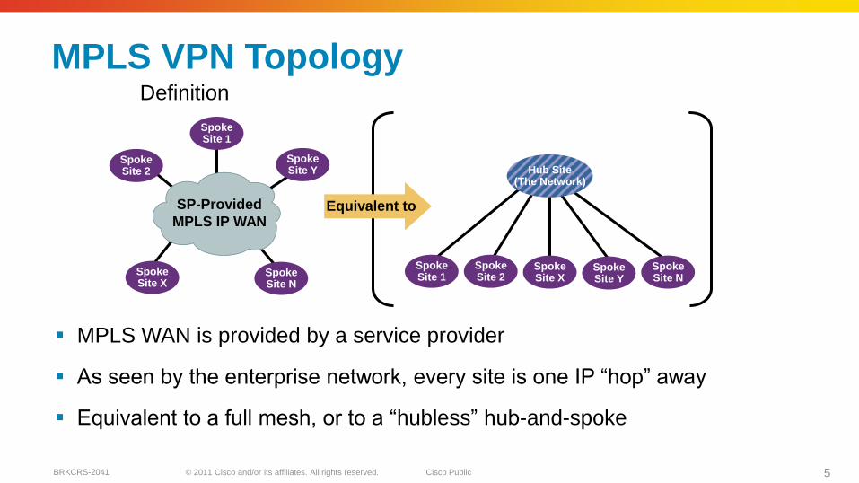
MPLS VPN Topology
MPLS WAN is provided by a service provider
As seen by the enterprise network, every site is one IP ―hop‖ away
Equivalent to a full mesh, or to a ―hubless‖ hub-and-spoke
SpokeSite 1
SpokeSite 2
SpokeSite N
SpokeSite Y
SpokeSite X
SpokeSite 1
SpokeSite N
SpokeSite 2
SpokeSite X
Hub Site(The Network)
SpokeSite Y
Equivalent toSP-Provided
MPLS IP WAN
Definition
© 2011 Cisco and/or its affiliates. All rights reserved. Cisco PublicBRKCRS-2041 6
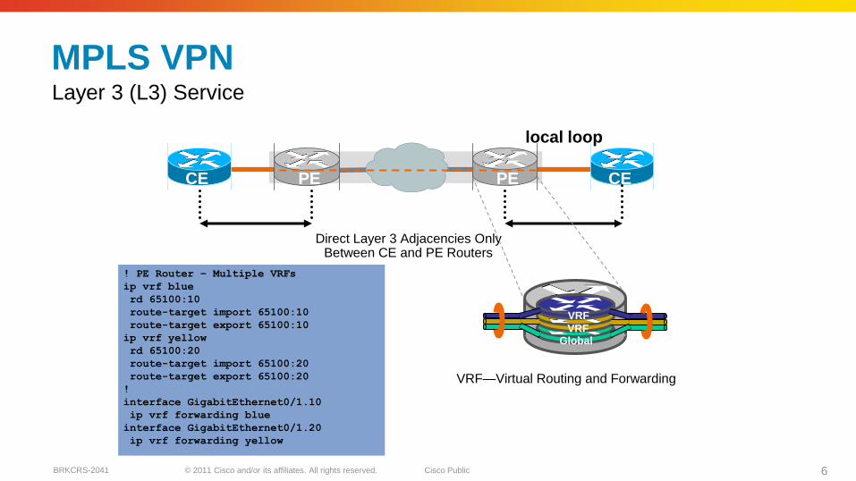
MPLS VPN
Direct Layer 3 Adjacencies Only Between CE and PE Routers
Layer 3 (L3) Service
CE CEPE PE
local loop
VRF
VRFGlobal
VRF—Virtual Routing and Forwarding
! PE Router – Multiple VRFs
ip vrf blue
rd 65100:10
route-target import 65100:10
route-target export 65100:10
ip vrf yellow
rd 65100:20
route-target import 65100:20
route-target export 65100:20
!
interface GigabitEthernet0/1.10
ip vrf forwarding blue
interface GigabitEthernet0/1.20
ip vrf forwarding yellow
© 2011 Cisco and/or its affiliates. All rights reserved. Cisco PublicBRKCRS-2041 7
MPLS VPN Design Trends Single Carrier Designs:
Enterprise will home all sites into a single carrier to provide L3 MPLS VPN connectivity.
Pro: Simpler design with consistent features
Con: Bound to single carrier for feature velocity
Con: Does not protect against MPLS cloud failure with Single Provider
Dual Carrier Designs:
Enterprise will single or dual home sites into one or both carriers to provide L3 MPLS VPN connectivity.
Pro: Protects against MPLS service failure with Single Provider
Pro: Potential business leverage for better competitive pricing
Con: Increased design complexity due to Service Implementation Differences (e.g. QoS, BGP AS Topology)
Con: Feature differences between providers could force customer to use least common denominator features.
Variants of these designs and site connectivity:
Encryption Overlay (e.g. IPSec, DMVPN, GET VPN, etc.)
Sites with On-demand / Permanent backup links
© 2011 Cisco and/or its affiliates. All rights reserved. Cisco PublicBRKCRS-2041 8
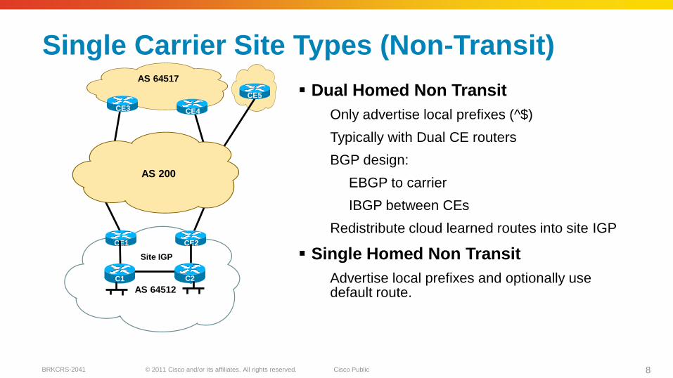
Single Carrier Site Types (Non-Transit)
Dual Homed Non Transit
Only advertise local prefixes (^$)
Typically with Dual CE routers
BGP design:
EBGP to carrier
IBGP between CEs
Redistribute cloud learned routes into site IGP
Single Homed Non Transit
Advertise local prefixes and optionally use default route.
CE1
C1
CE2
AS 64512
C2
CE5
Site IGP
CE3 CE4
AS 64517
AS 200
© 2011 Cisco and/or its affiliates. All rights reserved. Cisco PublicBRKCRS-2041 9
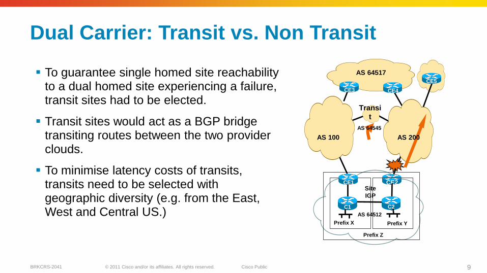
Dual Carrier: Transit vs. Non Transit
C1
CE2
Prefix Z
AS 64512
C2
CE5
Prefix X Prefix Y
Site
IGP
CE3 CE4
AS 64517
Transi
t
AS 100 AS 200
AS 64545
CE1
To guarantee single homed site reachabilityto a dual homed site experiencing a failure, transit sites had to be elected.
Transit sites would act as a BGP bridge transiting routes between the two provider clouds.
To minimise latency costs of transits, transits need to be selected with geographic diversity (e.g. from the East, West and Central US.)
© 2011 Cisco and/or its affiliates. All rights reserved. Cisco PublicBRKCRS-2041 10
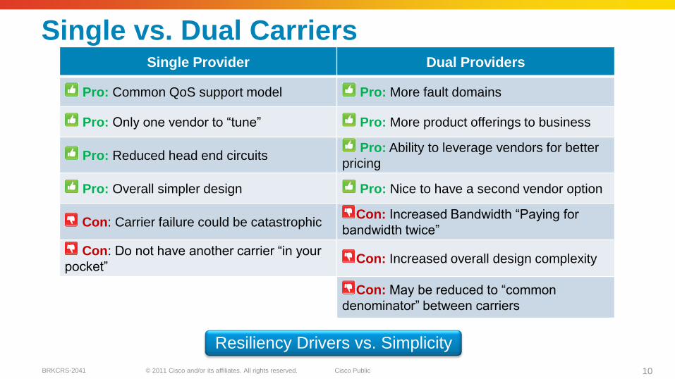
Single Provider Dual Providers
Pro: Common QoS support model Pro: More fault domains
Pro: Only one vendor to ―tune‖ Pro: More product offerings to business
Pro: Reduced head end circuits Pro: Ability to leverage vendors for better
pricing
Pro: Overall simpler design Pro: Nice to have a second vendor option
Con: Carrier failure could be catastrophicCon: Increased Bandwidth ―Paying for
bandwidth twice‖
Con: Do not have another carrier ―in your
pocket‖Con: Increased overall design complexity
Con: May be reduced to ―common
denominator‖ between carriers
Resiliency Drivers vs. Simplicity
Single vs. Dual Carriers

© 2011 Cisco and/or its affiliates. All rights reserved. Cisco PublicBRKCRS-2041 11
WAN Overlay Technologies

© 2011 Cisco and/or its affiliates. All rights reserved. Cisco PublicBRKCRS-2041 12
Tunnelling Technologies
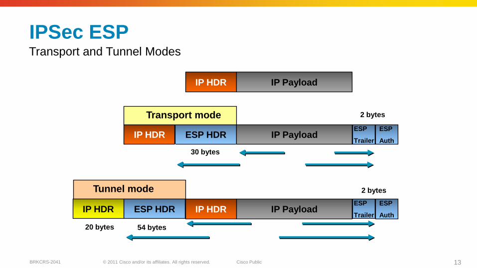
IPSec—Encapsulating Security Payload (ESP)
–Strong encryption
–IP Unicast only
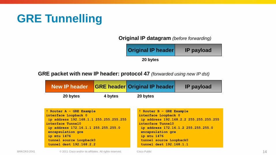
Generic Routing Encapsulation (GRE)
–IP Unicast, Multicast, Broadcast
–Multiprotocol support
Layer 2 Tunnelling Protocol—Version 3 (L2TPv3)
–Layer 2 payloads (Ethernet, Serial,…)
–Pseudowire capable
Packet Encapsulation over IP
Tunnels
© 2011 Cisco and/or its affiliates. All rights reserved. Cisco PublicBRKCRS-2041 13
IP HDR
Encrypted
ESP HDR
IP HDR
IP Payload
Tunnel mode
Transport mode
ESP
Trailer
ESP
Auth
Authenticated
Encrypted
Authenticated
IPSec ESP
IP Payload
IP Payload
IP HDRESP HDRIP HDRESP
Trailer
ESP
Auth
Transport and Tunnel Modes
20 bytes
30 bytes
54 bytes
2 bytes
2 bytes
© 2011 Cisco and/or its affiliates. All rights reserved. Cisco PublicBRKCRS-2041 14
GRE Tunnelling
Original IP header IP payloadGRE headerNew IP header
20 bytes 20 bytes4 bytes
GRE packet with new IP header: protocol 47 (forwarded using new IP dst)
Original IP header IP payload
20 bytes
Original IP datagram (before forwarding)
! Router A – GRE Example
interface Loopback 0
ip address 192.168.1.1 255.255.255.255
interface Tunnel0
ip address 172.16.1.1 255.255.255.0
encapsulation gre
ip mtu 1476
tunnel source Loopback0
tunnel dest 192.168.2.2
! Router B – GRE Example
interface Loopback 0
ip address 192.168.2.2 255.255.255.255
interface Tunnel0
ip address 172.16.1.2 255.255.255.0
encapsulation gre
ip mtu 1476
tunnel source Loopback0
tunnel dest 192.168.1.1

© 2011 Cisco and/or its affiliates. All rights reserved. Cisco PublicBRKCRS-2041 15
VPN Technology
EzVPN
Spoke
GET GMDMVPN
Spoke
DMVPN
Spoke
Data Centre
Internet Edge
WAN Edge
GET GM GET GM
Positioning EzVPN, DMVPN, GETVPN
MPLS/Privat
e Network
KSKS
GMGM
IPsec IPsec
Internet/
Shared
Network*
* Note: DMVPN Can Also Be Used on MPLS/Private Network
© 2011 Cisco and/or its affiliates. All rights reserved. Cisco PublicBRKCRS-2041 16
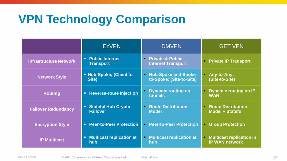
VPN Technology Comparison
EzVPN DMVPN GET VPN
Infrastructure Network Public Internet
Transport Private & Public
Internet Transport Private IP Transport
Network Style Hub-Spoke; (Client to
Site) Hub-Spoke and Spoke-
to-Spoke; (Site-to-Site) Any-to-Any;
(Site-to-Site)
Routing Reverse-route Injection Dynamic routing on
tunnels Dynamic routing on IP
WAN
Failover Redundancy Stateful Hub Crypto
Failover Route Distribution
Model Route Distribution
Model + Stateful
Encryption Style Peer-to-Peer Protection Peer-to-Peer Protection Group Protection
IP Multicast Multicast replication at
hub Multicast replication at
hub Multicast replication in
IP WAN network
© 2011 Cisco and/or its affiliates. All rights reserved. Cisco PublicBRKCRS-2041 17
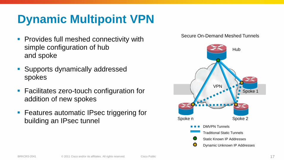
Dynamic Multipoint VPN
Provides full meshed connectivity with simple configuration of hub and spoke
Supports dynamically addressed spokes
Facilitates zero-touch configuration for addition of new spokes
Features automatic IPsec triggering for building an IPsec tunnel Spoke n
Traditional Static Tunnels
DMVPN Tunnels
Static Known IP Addresses
Dynamic Unknown IP Addresses
Hub
VPNSpoke 1
Spoke 2
Secure On-Demand Meshed Tunnels
© 2011 Cisco and/or its affiliates. All rights reserved. Cisco PublicBRKCRS-2041 18
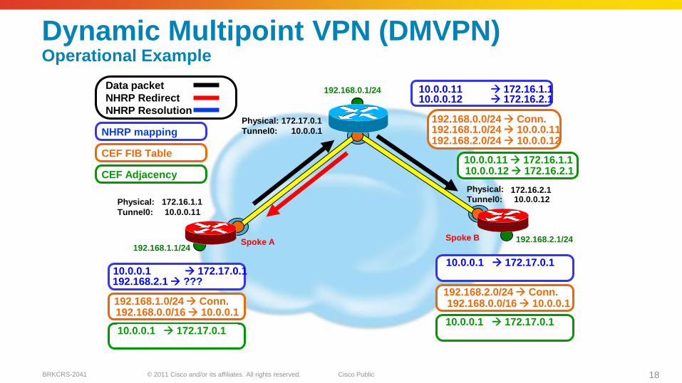
Dynamic Multipoint VPN (DMVPN)Operational Example
Spoke A192.168.1.1/24
192.168.2.1/24
Physical: 172.17.0.1
Tunnel0: 10.0.0.1
Spoke B
Physical: (dynamic)
Tunnel0: 10.0.0.11
Physical: (dynamic)
Tunnel0: 10.0.0.12
10.0.0.11 172.16.1.110.0.0.12 172.16.2.1
192.168.0.1/24
192.168.1.0/24 10.0.0.11192.168.2.0/24 10.0.0.12
192.168.0.0/24 Conn.
CEF FIB Table
172.16.1.1
172.16.2.1
NHRP mapping
192.168.1.0/24 Conn.
10.0.0.1 172.17.0.1
192.168.2.0/24 Conn.
10.0.0.1 172.17.0.1
192.168.2.1 ???
192.168.0.0/16 10.0.0.1192.168.0.0/16 10.0.0.1
CEF Adjacency
10.0.0.1 172.17.0.1
10.0.0.11 172.16.1.1
Data packet
NHRP Redirect
NHRP Resolution
10.0.0.1 172.17.0.1
10.0.0.12 172.16.2.1
© 2011 Cisco and/or its affiliates. All rights reserved. Cisco PublicBRKCRS-2041 19
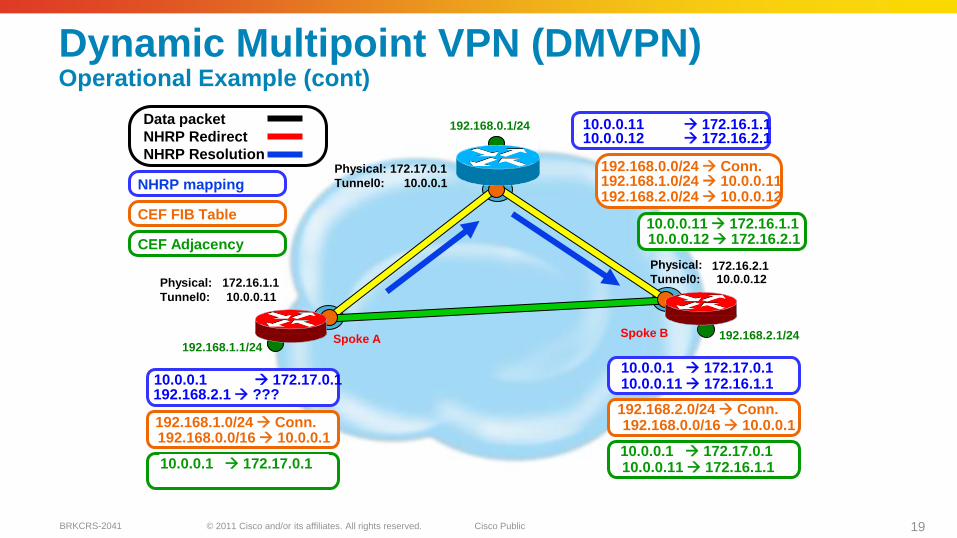
Dynamic Multipoint VPN (DMVPN)Operational Example (cont)
Spoke A192.168.1.1/24
192.168.2.1/24
Physical: 172.17.0.1
Tunnel0: 10.0.0.1
Spoke B
Physical: (dynamic)
Tunnel0: 10.0.0.11
Physical: (dynamic)
Tunnel0: 10.0.0.12
10.0.0.11 172.16.1.110.0.0.12 172.16.2.1
192.168.0.1/24
192.168.1.0/24 10.0.0.11192.168.2.0/24 10.0.0.12
192.168.0.0/24 Conn.
CEF FIB Table
172.16.1.1
172.16.2.1
NHRP mapping
192.168.1.0/24 Conn.
10.0.0.1 172.17.0.1
192.168.2.0/24 Conn.
10.0.0.1 172.17.0.1
192.168.2.1 ???
192.168.0.0/16 10.0.0.1192.168.0.0/16 10.0.0.1
CEF Adjacency
10.0.0.1 172.17.0.110.0.0.11 172.16.1.1
10.0.0.11 172.16.1.1
10.0.0.11 172.16.1.1
Data packet
NHRP Redirect
NHRP Resolution
10.0.0.1 172.17.0.1
10.0.0.12 172.16.2.1
10.0.0.11 172.16.1.1
© 2011 Cisco and/or its affiliates. All rights reserved. Cisco PublicBRKCRS-2041 20
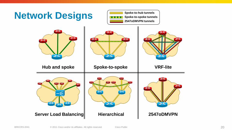
Network Designs
Hub and spoke Spoke-to-spoke
Server Load Balancing Hierarchical
Spoke-to-hub tunnels
Spoke-to-spoke tunnels
2547oDMVPN tunnels
VRF-lite
2547oDMVPN
© 2011 Cisco and/or its affiliates. All rights reserved. Cisco PublicBRKCRS-2041 21
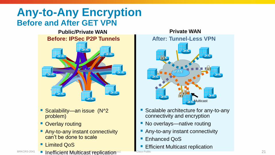
Any-to-Any EncryptionBefore and After GET VPN
Scalability—an issue (N^2 problem)
Overlay routing
Any-to-any instant connectivity can‘t be done to scale
Limited QoS
Inefficient Multicast replication
WAN
Multicast
Before: IPSec P2P Tunnels After: Tunnel-Less VPN
Scalable architecture for any-to-any connectivity and encryption
No overlays—native routing
Any-to-any instant connectivity
Enhanced QoS
Efficient Multicast replication
Public/Private WAN Private WAN

© 2011 Cisco and/or its affiliates. All rights reserved. Cisco PublicBRKCRS-2041 22
Group Security Functions
Group
Member
Group
Member
Group
Member
Group
Member
Key Server
Routing
Members
Group Member Encryption Devices Route Between Secure/ Unsecure
RegionsMulticast Participation
Key Server Validate Group Members Manage Security Policy Create Group Keys Distribute Policy/Keys
Routing Member Forwarding Replication Routing
© 2011 Cisco and/or its affiliates. All rights reserved. Cisco PublicBRKCRS-2041 23
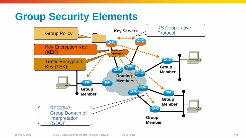
Group Security Elements
Group
Member
Group
Member
Group
Member
Group
Member
Key Servers
Routing
Members
Key Encryption Key (KEK)
Traffic Encryption Key (TEK)
Group Policy
RFC3547:Group Domain of Interpretation (GDOI)
KS Cooperative Protocol
© 2011 Cisco and/or its affiliates. All rights reserved. Cisco PublicBRKCRS-2041 24
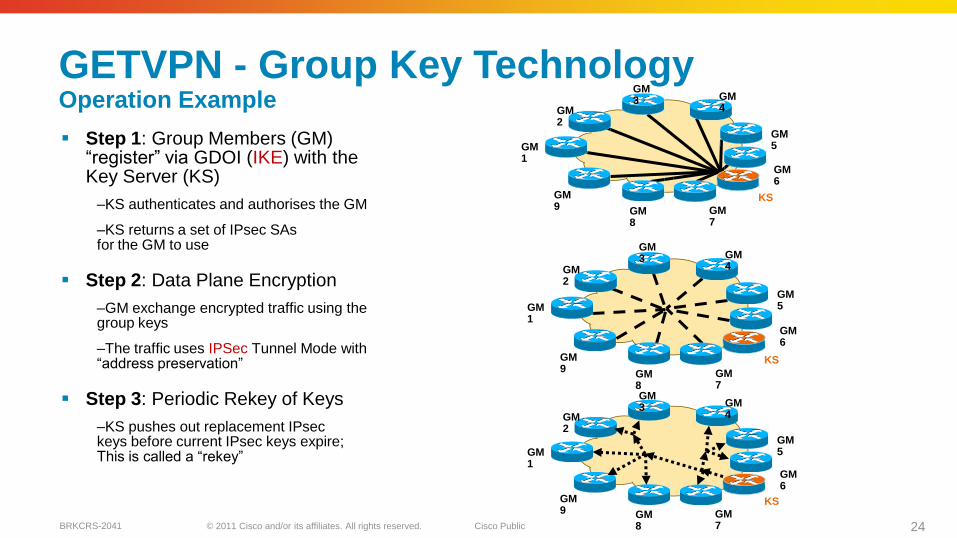
GETVPN - Group Key TechnologyOperation Example
Step 1: Group Members (GM) ―register‖ via GDOI (IKE) with the Key Server (KS)
–KS authenticates and authorises the GM
–KS returns a set of IPsec SAsfor the GM to use
Step 2: Data Plane Encryption
–GM exchange encrypted traffic using the group keys
–The traffic uses IPSec Tunnel Mode with ―address preservation‖
Step 3: Periodic Rekey of Keys
–KS pushes out replacement IPseckeys before current IPsec keys expire; This is called a ―rekey‖
GM1
GM2
GM3 GM
4
GM5
GM6
GM7
GM8
GM9
KS
GM1
GM2
GM3 GM
4
GM5
GM6
GM7
GM8
GM9
KS
GM1
GM2
GM3 GM
4
GM5
GM6
GM7
GM8
GM9
KS

© 2011 Cisco and/or its affiliates. All rights reserved. Cisco PublicBRKCRS-2041 25
WAN Optimisation
© 2011 Cisco and/or its affiliates. All rights reserved. Cisco PublicBRKCRS-2041 26
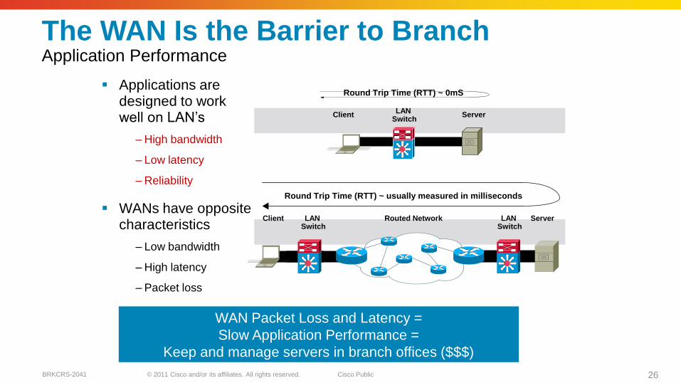
The WAN Is the Barrier to Branch Application Performance
Applications are designed to work well on LAN‘s
– High bandwidth
– Low latency
– Reliability
WANs have opposite characteristics
– Low bandwidth
– High latency
– Packet loss
Round Trip Time (RTT) ~ 0mS
ClientLAN
SwitchServer
Round Trip Time (RTT) ~ usually measured in milliseconds
ServerClient LAN Switch
LAN Switch
Routed Network
WAN Packet Loss and Latency =
Slow Application Performance =
Keep and manage servers in branch offices ($$$)
© 2011 Cisco and/or its affiliates. All rights reserved. Cisco PublicBRKCRS-2041 27
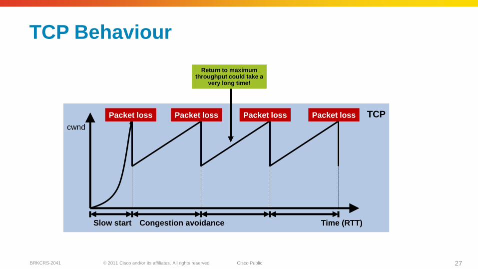
TCP Behaviour
Time (RTT)Slow start Congestion avoidance
Packet loss Packet loss Packet loss
cwnd
Packet loss TCP
Return to maximumthroughput could take a
very long time!
© 2011 Cisco and/or its affiliates. All rights reserved. Cisco PublicBRKCRS-2041 28
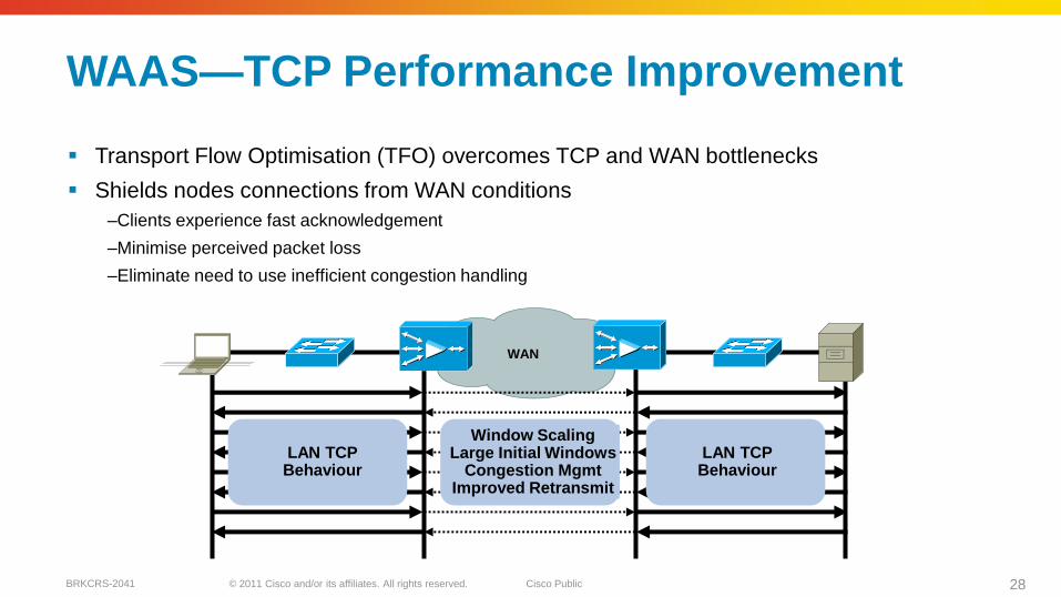
WAN
WAAS—TCP Performance Improvement
Transport Flow Optimisation (TFO) overcomes TCP and WAN bottlenecks
Shields nodes connections from WAN conditions
–Clients experience fast acknowledgement
–Minimise perceived packet loss
–Eliminate need to use inefficient congestion handling
LAN TCPBehaviour
LAN TCPBehaviour
Window ScalingLarge Initial Windows
Congestion MgmtImproved Retransmit
© 2011 Cisco and/or its affiliates. All rights reserved. Cisco PublicBRKCRS-2041 29
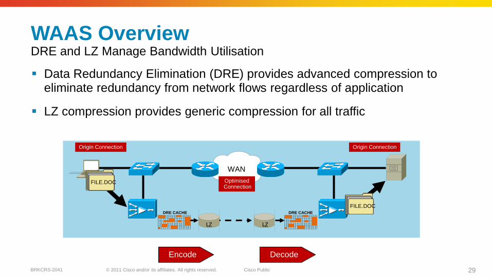
WAAS OverviewDRE and LZ Manage Bandwidth Utilisation
Data Redundancy Elimination (DRE) provides advanced compression to eliminate redundancy from network flows regardless of application
LZ compression provides generic compression for all traffic
FILE.DOC
DRE CACHE DRE CACHE
FILE.DOC
WAN
LZ LZ
Origin ConnectionOrigin Connection
OptimisedConnection
Encode Decode

© 2011 Cisco and/or its affiliates. All rights reserved. Cisco PublicBRKCRS-2041 30
Comparing TCP and Transport Flow Optimisation
Time (RTT)Slow start Congestion avoidance
cwnd
TCP
TFO
Cisco TFO provides significant throughput improvements over standard TCP implementations
© 2011 Cisco and/or its affiliates. All rights reserved. Cisco PublicBRKCRS-2041 31
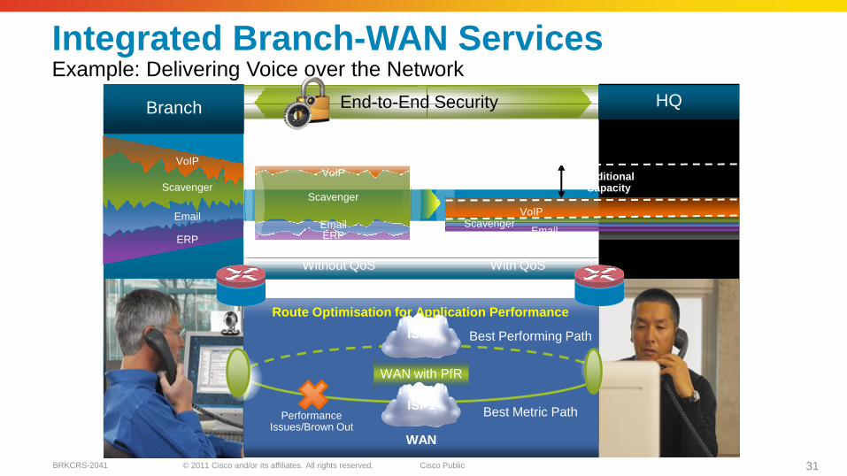
End-to-End Security
WAN Optimisation for Application Performance
Route Optimisation for Application Performance
Performance Issues/Brown Out
WAN with PfR
Best Performing Path
Best Metric PathISP1
ISP2
Without Cisco WAAS Without QoS
WAN
EmailERP
Scavenger
VoIP
ERP
Scavenger
VoIP
Branch HQ
AdditionalCapacity
With Cisco WAAS With QoS
EmailERP
ScavengerVoIP
Integrated Branch-WAN Services Example: Delivering Voice over the Network

© 2011 Cisco and/or its affiliates. All rights reserved. Cisco PublicBRKCRS-2041 32
Wide Area Network Quality of Service
© 2011 Cisco and/or its affiliates. All rights reserved. Cisco PublicBRKCRS-2041 33
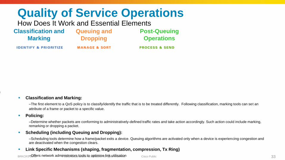
Quality of Service OperationsHow Does It Work and Essential Elements
Classification and Marking:
–The first element to a QoS policy is to classify/identify the traffic that is to be treated differently. Following classification, marking tools can set an
attribute of a frame or packet to a specific value.
Policing:
–Determine whether packets are conforming to administratively-defined traffic rates and take action accordingly. Such action could include marking, remarking or dropping a packet.
Scheduling (including Queuing and Dropping):
–Scheduling tools determine how a frame/packet exits a device. Queuing algorithms are activated only when a device is experiencing congestion and are deactivated when the congestion clears.
Link Specific Mechanisms (shaping, fragmentation, compression, Tx Ring)
–Offers network administrators tools to optimise link utilisation
Classification and
Marking
Queuing and
Dropping
Post-Queuing
Operations
© 2011 Cisco and/or its affiliates. All rights reserved. Cisco PublicBRKCRS-2041 34
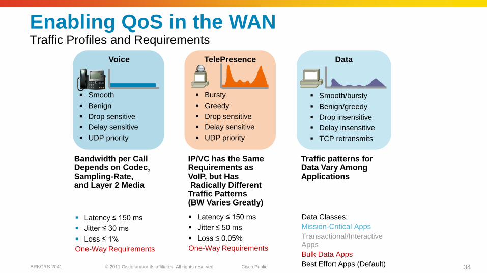
Enabling QoS in the WANTraffic Profiles and Requirements
Latency ≤ 150 ms
Jitter ≤ 30 ms
Loss ≤ 1%
One-Way Requirements
Smooth
Benign
Drop sensitive
Delay sensitive
UDP priority
Voice
Bandwidth per CallDepends on Codec,Sampling-Rate, and Layer 2 Media
Bursty
Greedy
Drop sensitive
Delay sensitive
UDP priority
TelePresence
Latency ≤ 150 ms
Jitter ≤ 50 ms
Loss ≤ 0.05%
One-Way Requirements
IP/VC has the SameRequirements as VoIP, but HasRadically Different Traffic Patterns (BW Varies Greatly)
Smooth/bursty
Benign/greedy
Drop insensitive
Delay insensitive
TCP retransmits
Data
Data Classes:
Mission-Critical Apps
Transactional/Interactive Apps
Bulk Data Apps
Best Effort Apps (Default)
Traffic patterns for Data Vary Among Applications

© 2011 Cisco and/or its affiliates. All rights reserved. Cisco PublicBRKCRS-2041 35
20 msec
Voice Packets
Bytes
200
600
1000
Audio
Sample
s
1400
Time
200
600
1000
1400
33 msec
Video PacketsVideo
Frame
Video
Frame
Video
Frame
QoS ConsiderationsVoice vs. Video—At the Packet Level
© 2011 Cisco and/or its affiliates. All rights reserved. Cisco PublicBRKCRS-2041 36
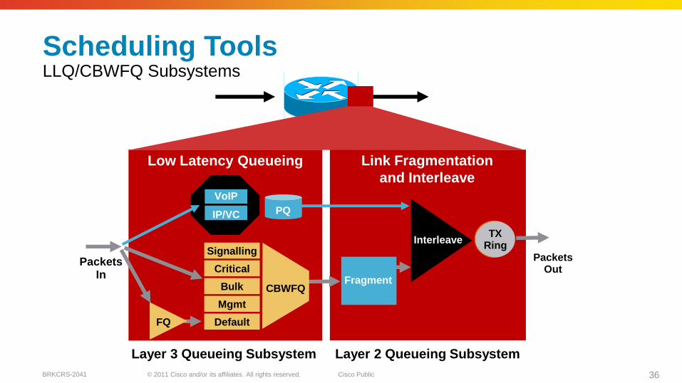
Police
Scheduling ToolsLLQ/CBWFQ Subsystems
CBWFQFragment
Interleave
FQ
Link Fragmentation
and Interleave
Low Latency Queueing
PacketsOut
PacketsIn
VoIP
IP/VC PQ
Layer 3 Queueing Subsystem Layer 2 Queueing Subsystem
Signalling
Critical
Bulk
Mgmt
Default
TXRing
© 2011 Cisco and/or its affiliates. All rights reserved. Cisco PublicBRKCRS-2041 37
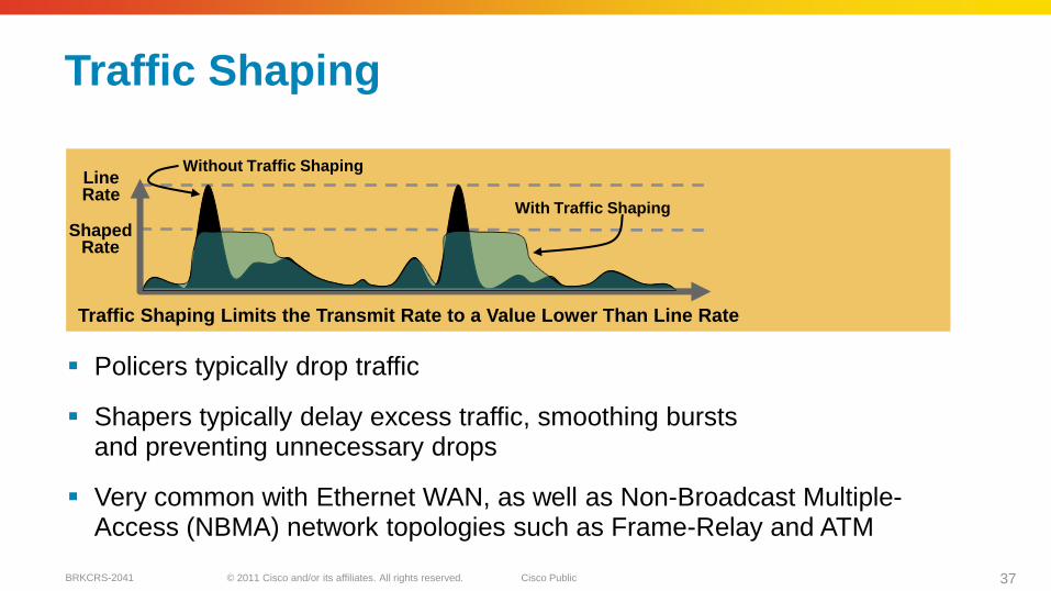
Traffic Shaping
Policers typically drop traffic
Shapers typically delay excess traffic, smoothing bursts and preventing unnecessary drops
Very common with Ethernet WAN, as well as Non-Broadcast Multiple-Access (NBMA) network topologies such as Frame-Relay and ATM
With Traffic Shaping
Without Traffic ShapingLineRate
ShapedRate
Traffic Shaping Limits the Transmit Rate to a Value Lower Than Line Rate

© 2011 Cisco and/or its affiliates. All rights reserved. Cisco PublicBRKCRS-2041 38
MPLS VPN
Branch 1
Branch 2
Outbound Policies: Inbound Policies:
HQoS Shaper (if required)
+ LLQ for VoIP (EF) Trust DSCP
+ LLQ or CBWFQ for RT-Interactive (CS4)
+ Remark RTI (if necessary) + Restore RT-Interactive to CS4 (if necessary)
+ CBWFQ for Signalling (CS3)
+ Remark Signalling (if necessary) + Restore Signalling to CS3 (if necessary)
≤ 33%of BW
Enterprise Subscriber (Unmanaged CE Routers)
Service Provider:Outbound Policies: Inbound Policies:
+ LLQ for Real-Time Trust DSCP
+ CBWFQ for Critical Data Police on a per-Class Basis
CE Routers CE RoutersPE Routers
Campus VPN
Block
E
E
E
E
F
F
F
F
F
E
MPLS VPN QoS DesignMPLS VPN Port QoS Roles
© 2011 Cisco and/or its affiliates. All rights reserved. Cisco PublicBRKCRS-2041 39
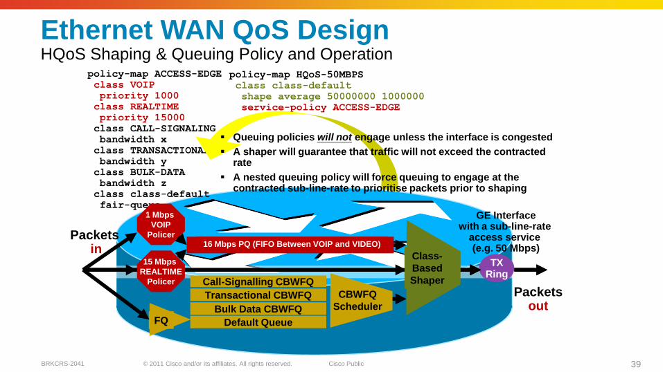
TXRing
policy-map ACCESS-EDGE
class VOIP
priority 1000
class REALTIME
priority 15000
class CALL-SIGNALING
bandwidth x
class TRANSACTIONAL
bandwidth y
class BULK-DATA
bandwidth z
class class-default
fair-queue
Packets in
Packetsout
policy-map HQoS-50MBPS
class class-default
shape average 50000000 1000000
service-policy ACCESS-EDGE
CBWFQ
Scheduler
FQ
Call-Signalling CBWFQ
Transactional CBWFQ
Bulk Data CBWFQ
Default Queue
1 Mbps
VOIP
Policer
15 Mbps
REALTIME
Policer
16 Mbps PQ (FIFO Between VOIP and VIDEO)
Class-
Based
Shaper
GE Interfacewith a sub-line-rate
access service (e.g. 50 Mbps)
Queuing policies will not engage unless the interface is congested
A shaper will guarantee that traffic will not exceed the contracted rate
A nested queuing policy will force queuing to engage at the contracted sub-line-rate to prioritise packets prior to shaping
Ethernet WAN QoS DesignHQoS Shaping & Queuing Policy and Operation

© 2011 Cisco and/or its affiliates. All rights reserved. Cisco PublicBRKCRS-2041 40
WAN Architecture Design Considerations
© 2011 Cisco and/or its affiliates. All rights reserved. Cisco PublicBRKCRS-2041 41
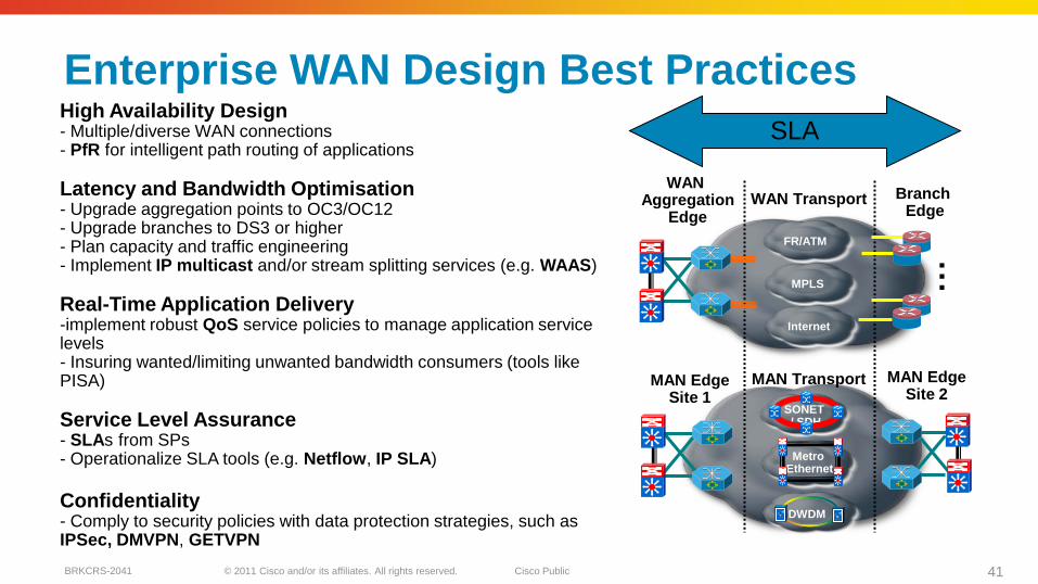
High Availability Design- Multiple/diverse WAN connections- PfR for intelligent path routing of applications
Latency and Bandwidth Optimisation- Upgrade aggregation points to OC3/OC12- Upgrade branches to DS3 or higher- Plan capacity and traffic engineering- Implement IP multicast and/or stream splitting services (e.g. WAAS)
Real-Time Application Delivery-implement robust QoS service policies to manage application service levels- Insuring wanted/limiting unwanted bandwidth consumers (tools like PISA)
Service Level Assurance- SLAs from SPs- Operationalize SLA tools (e.g. Netflow, IP SLA)
Confidentiality- Comply to security policies with data protection strategies, such as IPSec, DMVPN, GETVPN
WAN Transport Branch Edge
MAN EdgeSite 1
WAN Aggregation
Edge
SONET / SDH
DWDM
MAN EdgeSite 2
Metro Ethernet
MAN Transport
FR/ATM
MPLS
Internet
…
SLA
Enterprise WAN Design Best Practices
© 2011 Cisco and/or its affiliates. All rights reserved. Cisco PublicBRKCRS-2041 42
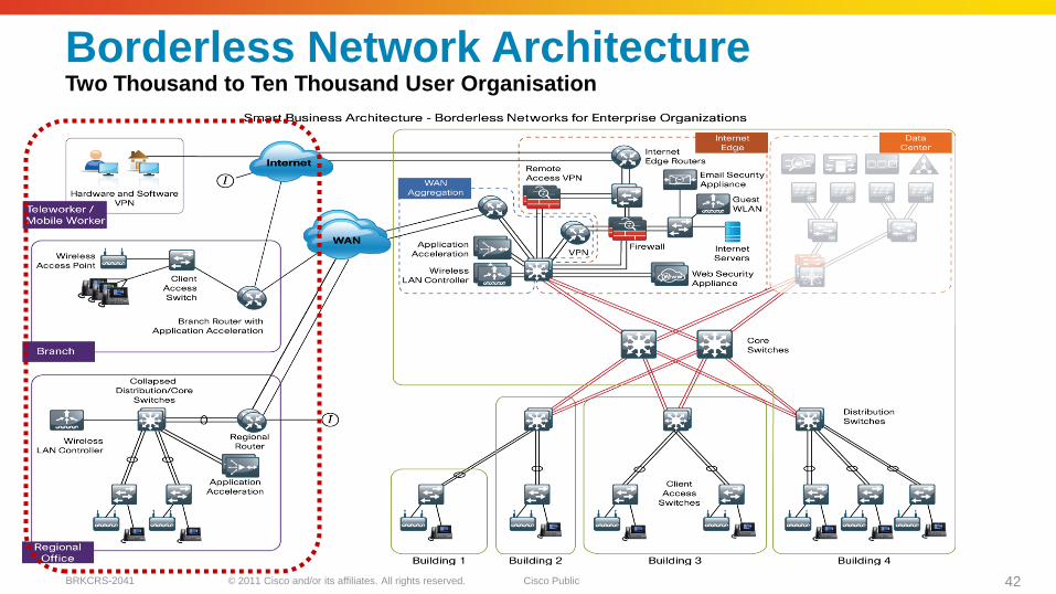
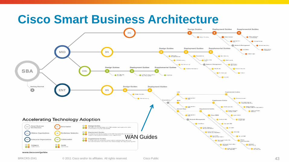
Borderless Network ArchitectureTwo Thousand to Ten Thousand User Organisation
© 2011 Cisco and/or its affiliates. All rights reserved. Cisco PublicBRKCRS-2041 43
Cisco Smart Business Architecture
WAN Guides
© 2011 Cisco and/or its affiliates. All rights reserved. Cisco PublicBRKCRS-2041 44
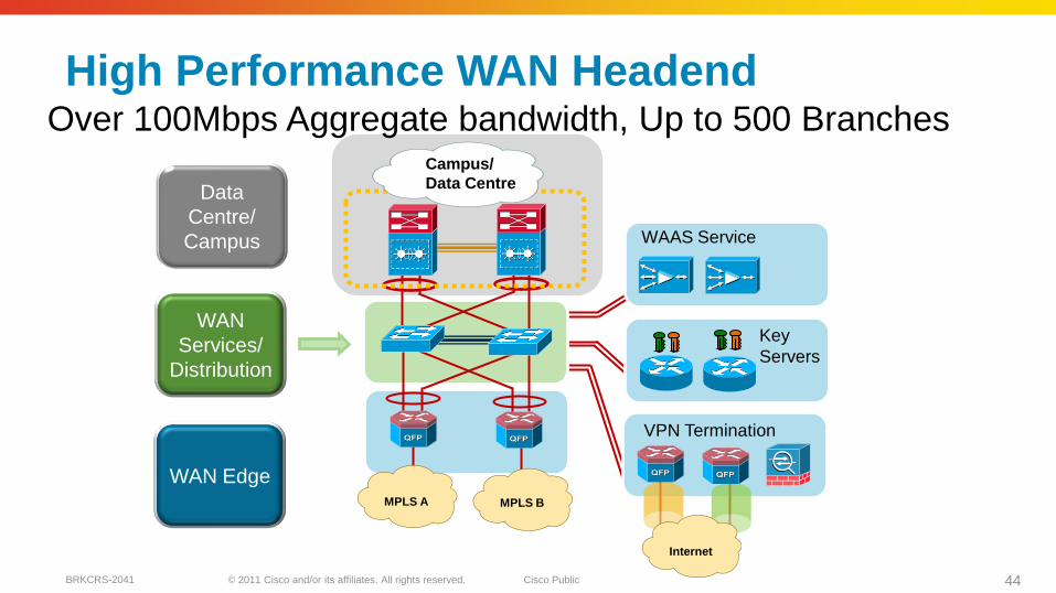
Data
Centre/
Campus
WAN
Services/
Distribution
High Performance WAN HeadendOver 100Mbps Aggregate bandwidth, Up to 500 Branches
MPLS A MPLS B
Campus/
Data Centre
WAAS Service
Key
Servers
VPN Termination
Internet
WAN Edge

© 2011 Cisco and/or its affiliates. All rights reserved. Cisco PublicBRKCRS-2041 45
Interne
tInterne
t
Interne
t
Interne
t
Remote Branch Transport & Redundancy Options
MPL
SMPLS WAN
MPLS +
Internet WAN
Interne
t
Internet WAN
MPL
SMPL
S
MPL
SMPL
S
MPL
S
MPL
S
Non-Redundant Redundant-Links Redundant-Links
& Routers
© 2011 Cisco and/or its affiliates. All rights reserved. Cisco PublicBRKCRS-2041 46
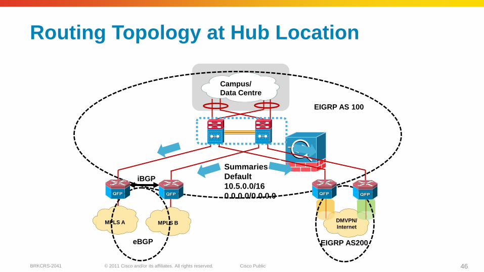
Routing Topology at Hub Location
MPLS A
Campus/
Data Centre
DMVPN/
InternetMPLS B
iBGP
EIGRP AS200
EIGRP AS 100
eBGP
Summaries +
Default
10.5.0.0/16
0.0.0.0/0.0.0.0
© 2011 Cisco and/or its affiliates. All rights reserved. Cisco PublicBRKCRS-2041 47
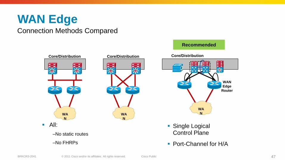
All:
–No static routes
–No FHRPs
WAN Edge
WA
N
Connection Methods Compared
WA
N
WAN
Edge
Router
WA
N
Core/Distribution
SiSi
Core/Distribution Core/Distribution
Single Logical Control Plane
Port-Channel for H/A
Recommended
© 2011 Cisco and/or its affiliates. All rights reserved. Cisco PublicBRKCRS-2041 48
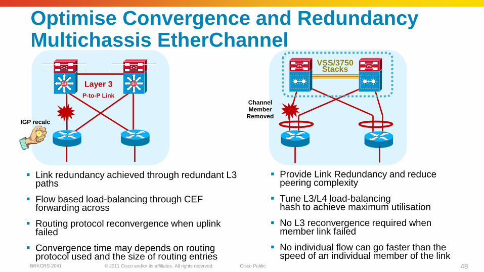
Optimise Convergence and RedundancyMultichassis EtherChannel
SiSi SiSi
P-to-P Link
Layer 3
Provide Link Redundancy and reduce peering complexity
Tune L3/L4 load-balancing hash to achieve maximum utilisation
No L3 reconvergence required when member link failed
No individual flow can go faster than the speed of an individual member of the link
VSS/3750Stacks
IGP recalc
Channel Member
Removed
Link redundancy achieved through redundant L3paths
Flow based load-balancing through CEFforwarding across
Routing protocol reconvergence when uplink failed
Convergence time may depends on routing protocol used and the size of routing entries
© 2011 Cisco and/or its affiliates. All rights reserved. Cisco PublicBRKCRS-2041 49
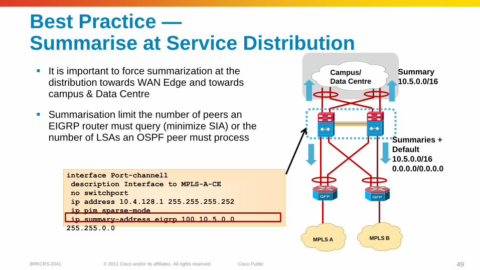
interface Port-channel1
description Interface to MPLS-A-CE
no switchport
ip address 10.4.128.1 255.255.255.252
ip pim sparse-mode
ip summary-address eigrp 100 10.5.0.0
255.255.0.0
Best Practice —Summarise at Service Distribution
It is important to force summarization at the distribution towards WAN Edge and towards campus & Data Centre
Summarisation limit the number of peers an EIGRP router must query (minimize SIA) or the number of LSAs an OSPF peer must process
MPLS BMPLS A
Campus/
Data Centre
Summaries +
Default
10.5.0.0/16
0.0.0.0/0.0.0.0
Summary
10.5.0.0/16
© 2011 Cisco and/or its affiliates. All rights reserved. Cisco PublicBRKCRS-2041 50
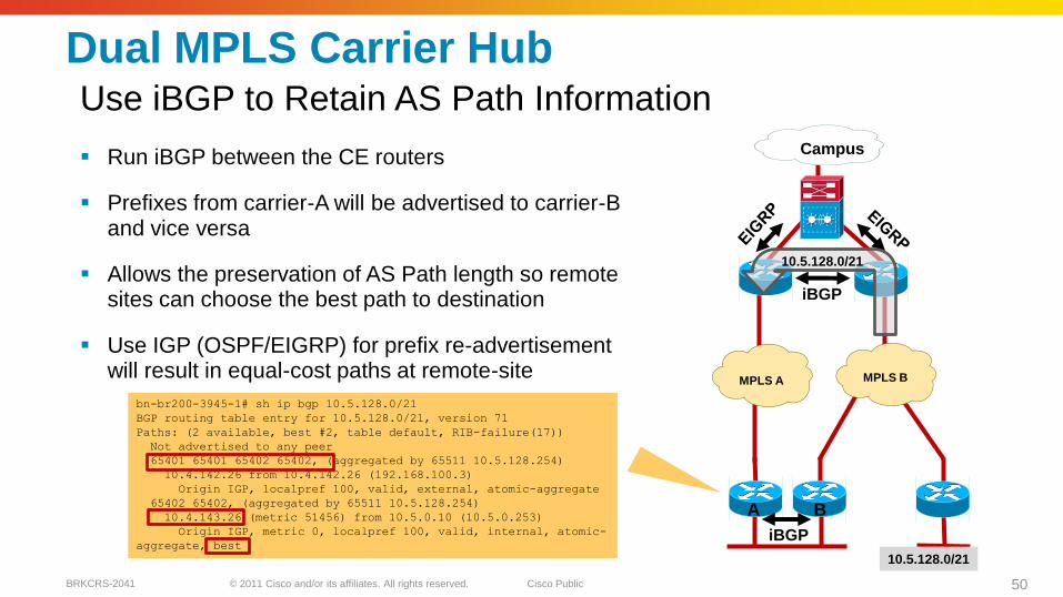
Dual MPLS Carrier Hub
Run iBGP between the CE routers
Prefixes from carrier-A will be advertised to carrier-B and vice versa
Allows the preservation of AS Path length so remote sites can choose the best path to destination
Use IGP (OSPF/EIGRP) for prefix re-advertisement will result in equal-cost paths at remote-site
Use iBGP to Retain AS Path Information
MPLS B
Campus
iBGP
MPLS A
iBGP
10.5.128.0/21
bn-br200-3945-1# sh ip bgp 10.5.128.0/21
BGP routing table entry for 10.5.128.0/21, version 71
Paths: (2 available, best #2, table default, RIB-failure(17))
Not advertised to any peer
65401 65401 65402 65402, (aggregated by 65511 10.5.128.254)
10.4.142.26 from 10.4.142.26 (192.168.100.3)
Origin IGP, localpref 100, valid, external, atomic-aggregate
65402 65402, (aggregated by 65511 10.5.128.254)
10.4.143.26 (metric 51456) from 10.5.0.10 (10.5.0.253)
Origin IGP, metric 0, localpref 100, valid, internal, atomic-
aggregate, best
10.5.128.0/21
A B

© 2011 Cisco and/or its affiliates. All rights reserved. Cisco PublicBRKCRS-2041 51
Best Practice - Implement AS-Path Filter
Dual carrier sites can unintentionally become transit network during network failure event and causing network congestion due to transit traffic
Design the network so that transit path between two carriers only occurs at sites with enough bandwidth
Implement AS-Path filter to allow only locally originated routes to be advertised on the outbound updates for branches that should not be transit
Prevent Branch Site Becoming Transit Network
router bgp 65511
neighbor 10.4.142.26 route-map NO-TRANSIT-AS out
!
ip as-path access-list 10 permit ^$
!
route-map NO-TRANSIT-AS permit 10
match as-path 10
MPLS B
Campus
iBGP
MPLS A
A B
© 2011 Cisco and/or its affiliates. All rights reserved. Cisco PublicBRKCRS-2041 52
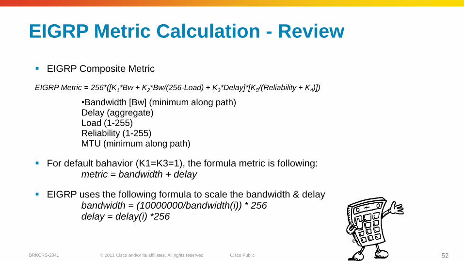
EIGRP Metric Calculation - Review
EIGRP Composite Metric
EIGRP Metric = 256*([K1*Bw + K2*Bw/(256-Load) + K3*Delay]*[K5/(Reliability + K4)])
•Bandwidth [Bw] (minimum along path)Delay (aggregate)Load (1-255)Reliability (1-255)MTU (minimum along path)
For default bahavior (K1=K3=1), the formula metric is following:metric = bandwidth + delay
EIGRP uses the following formula to scale the bandwidth & delaybandwidth = (10000000/bandwidth(i)) * 256 delay = delay(i) *256
© 2011 Cisco and/or its affiliates. All rights reserved. Cisco PublicBRKCRS-2041 53
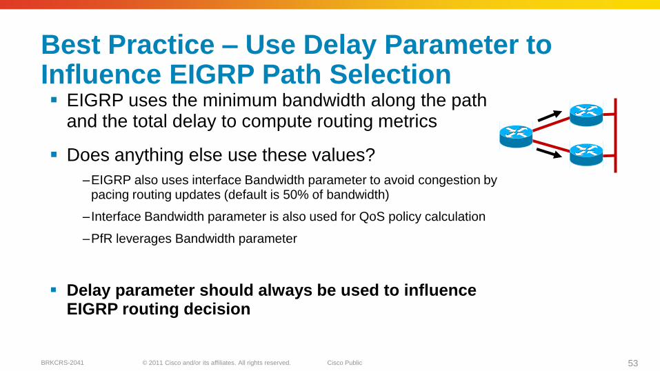
Best Practice – Use Delay Parameter to Influence EIGRP Path Selection EIGRP uses the minimum bandwidth along the path
and the total delay to compute routing metrics
Does anything else use these values?
–EIGRP also uses interface Bandwidth parameter to avoid congestion by pacing routing updates (default is 50% of bandwidth)
– Interface Bandwidth parameter is also used for QoS policy calculation
–PfR leverages Bandwidth parameter
Delay parameter should always be used to influence EIGRP routing decision
© 2011 Cisco and/or its affiliates. All rights reserved. Cisco PublicBRKCRS-2041 54
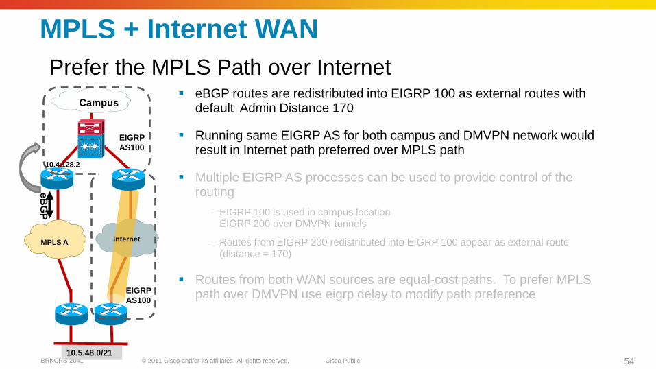
MPLS + Internet WAN
eBGP routes are redistributed into EIGRP 100 as external routes with default Admin Distance 170
Running same EIGRP AS for both campus and DMVPN network would result in Internet path preferred over MPLS path
Multiple EIGRP AS processes can be used to provide control of the routing
– EIGRP 100 is used in campus locationEIGRP 200 over DMVPN tunnels
– Routes from EIGRP 200 redistributed into EIGRP 100 appear as external route (distance = 170)
Routes from both WAN sources are equal-cost paths. To prefer MPLSpath over DMVPN use eigrp delay to modify path preference
Prefer the MPLS Path over Internet
MPLS A
Campus
EIGRP
AS100
Internet
10.4.128.2
eB
GP
10.5.48.0/21
EIGRP
AS100
© 2011 Cisco and/or its affiliates. All rights reserved. Cisco PublicBRKCRS-2041 55
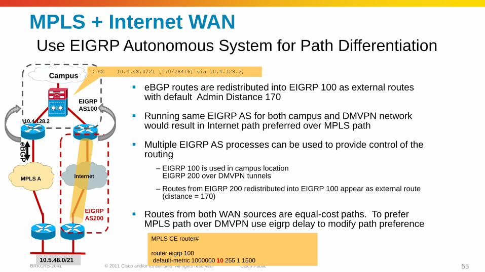
MPLS + Internet WAN
eBGP routes are redistributed into EIGRP 100 as external routes with default Admin Distance 170
Running same EIGRP AS for both campus and DMVPN network would result in Internet path preferred over MPLS path
Multiple EIGRP AS processes can be used to provide control of the routing
– EIGRP 100 is used in campus locationEIGRP 200 over DMVPN tunnels
– Routes from EIGRP 200 redistributed into EIGRP 100 appear as external route (distance = 170)
Routes from both WAN sources are equal-cost paths. To prefer MPLS path over DMVPN use eigrp delay to modify path preference
Use EIGRP Autonomous System for Path Differentiation
MPLS A
Campus
EIGRP
AS100
EIGRP
AS200
Internet
D EX 10.5.48.0/21 [170/28416] via 10.4.128.2,
10.4.128.2
eB
GP
10.5.48.0/21
MPLS CE router#
router eigrp 100
default-metric 1000000 10 255 1 1500
© 2011 Cisco and/or its affiliates. All rights reserved. Cisco PublicBRKCRS-2041 56
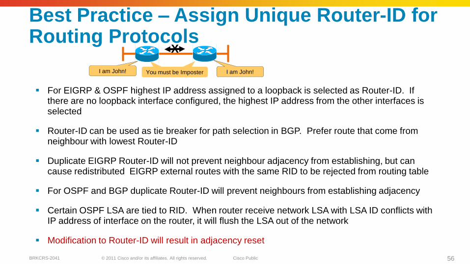
Best Practice – Assign Unique Router-ID for Routing Protocols
For EIGRP & OSPF highest IP address assigned to a loopback is selected as Router-ID. If there are no loopback interface configured, the highest IP address from the other interfaces is selected
Router-ID can be used as tie breaker for path selection in BGP. Prefer route that come from neighbour with lowest Router-ID
Duplicate EIGRP Router-ID will not prevent neighbour adjacency from establishing, but can cause redistributed EIGRP external routes with the same RID to be rejected from routing table
For OSPF and BGP duplicate Router-ID will prevent neighbours from establishing adjacency
Certain OSPF LSA are tied to RID. When router receive network LSA with LSA ID conflicts with IP address of interface on the router, it will flush the LSA out of the network
Modification to Router-ID will result in adjacency reset
I am John! I am John! You must be Imposter
X
© 2011 Cisco and/or its affiliates. All rights reserved. Cisco PublicBRKCRS-2041 57
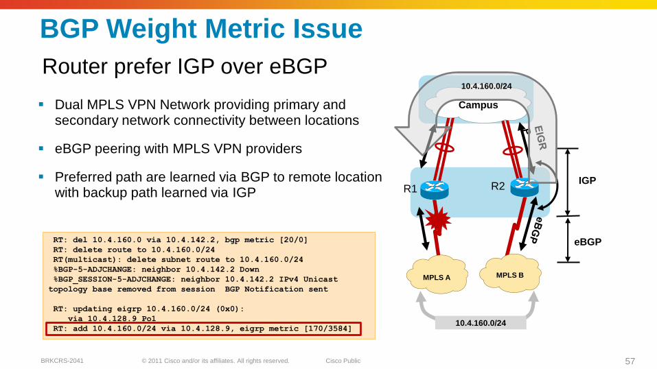
BGP Weight Metric Issue
Dual MPLS VPN Network providing primary and secondary network connectivity between locations
eBGP peering with MPLS VPN providers
Preferred path are learned via BGP to remote location with backup path learned via IGP
Router prefer IGP over eBGP
MPLS BMPLS A
eBGP
IGP
10.4.160.0/24
Campus
10.4.160.0/24
R1 R2
RT: del 10.4.160.0 via 10.4.142.2, bgp metric [20/0]
RT: delete route to 10.4.160.0/24
RT(multicast): delete subnet route to 10.4.160.0/24
%BGP-5-ADJCHANGE: neighbor 10.4.142.2 Down
%BGP_SESSION-5-ADJCHANGE: neighbor 10.4.142.2 IPv4 Unicast
topology base removed from session BGP Notification sent
RT: updating eigrp 10.4.160.0/24 (0x0):
via 10.4.128.9 Po1
RT: add 10.4.160.0/24 via 10.4.128.9, eigrp metric [170/3584]
© 2011 Cisco and/or its affiliates. All rights reserved. Cisco PublicBRKCRS-2041 58
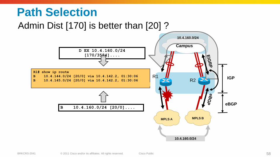
Path SelectionAdmin Dist [170] is better than [20] ?
MPLS BMPLS A
eBGP
IGP
10.4.160.0/24
CampusD EX 10.4.160.0/24
[170/3584]....
B 10.4.160.0/24 [20/0]....
R1# show ip route
B 10.4.144.0/24 [20/0] via 10.4.142.2, 01:30:06
B 10.4.145.0/24 [20/0] via 10.4.142.2, 01:30:06
D EX 10.4.160.0/24 [170/3584] via 10.4.128.9, 00:30:06
10.4.160.0/24
R1R2

© 2011 Cisco and/or its affiliates. All rights reserved. Cisco PublicBRKCRS-2041 59
BGP Route Selection Criteria
BGP Prefers Path with:
1. Highest Weight
2. Highest Local PREF
3. Locally originated via network or aggregate BGP
4. Shortest AS_PATH
5. Lowest Origin typeIGP>EGP>INCOMPLETE
6. Lowest MED
7. eBGP over iBGP paths
8. Lowest IGP metric to BGP next hop
© 2011 Cisco and/or its affiliates. All rights reserved. Cisco PublicBRKCRS-2041 60
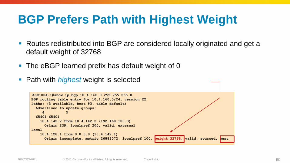
ASR1004-1#show ip bgp 10.4.160.0 255.255.255.0
BGP routing table entry for 10.4.160.0/24, version 22
Paths: (3 available, best #3, table default)
Advertised to update-groups:
4 5
65401 65401
10.4.142.2 from 10.4.142.2 (192.168.100.3)
Origin IGP, localpref 200, valid, external
Local
10.4.128.1 from 0.0.0.0 (10.4.142.1)
Origin incomplete, metric 26883072, localpref 100, weight 32768, valid, sourced, best
BGP Prefers Path with Highest Weight
Routes redistributed into BGP are considered locally originated and get a default weight of 32768
The eBGP learned prefix has default weight of 0
Path with highest weight is selected
© 2011 Cisco and/or its affiliates. All rights reserved. Cisco PublicBRKCRS-2041 61
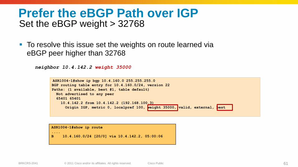
ASR1004-1#show ip bgp 10.4.160.0 255.255.255.0
BGP routing table entry for 10.4.160.0/24, version 22
Paths: (1 available, best #1, table default)
Not advertised to any peer
65401 65401
10.4.142.2 from 10.4.142.2 (192.168.100.3)
Origin IGP, metric 0, localpref 100, weight 35000, valid, external, best
Prefer the eBGP Path over IGP
To resolve this issue set the weights on route learned via eBGP peer higher than 32768
neighbor 10.4.142.2 weight 35000
Set the eBGP weight > 32768
ASR1004-1#show ip route
....
B 10.4.160.0/24 [20/0] via 10.4.142.2, 05:00:06

© 2011 Cisco and/or its affiliates. All rights reserved. Cisco PublicBRKCRS-2041 62
router eigrp 100
distribute-list route-map BLOCK-TAGGED-ROUTES
in
default-metric [BW] 100 255 1 1500
redistribute bgp 65511
route-map BLOCK-TAGGED-ROUTES deny 10
match tag 65401 65402
route-map BLOCK-TAGGED-ROUTES permit 20
Route Tag & Filter
Routes are implicitly tagged when distributed from eBGP to EIGRP with carrier AS
Use route-map to block re-learning of WAN routes via the distribution layer (already known via iBGP)
MPLS B
AS
65402
MPLS A
AS
65401
Campus/
Data Centre
EIGRP routes
from
distribution
layeriBGP
© 2011 Cisco and/or its affiliates. All rights reserved. Cisco PublicBRKCRS-2041 63
Securing WAN communication with GET VPN
© 2011 Cisco and/or its affiliates. All rights reserved. Cisco PublicBRKCRS-2041 64
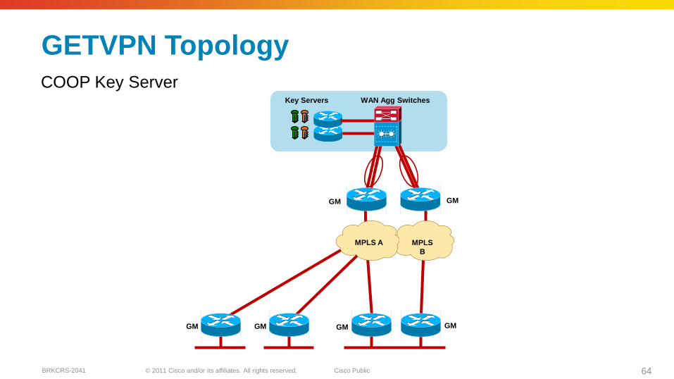
GETVPN Topology
COOP Key ServerWAN Agg SwitchesKey Servers
MPLS
B
MPLS A
GMGM
GM GM GM GM
© 2011 Cisco and/or its affiliates. All rights reserved. Cisco PublicBRKCRS-2041 65
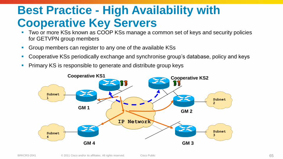
Best Practice - High Availability with Cooperative Key Servers Two or more KSs known as COOP KSs manage a common set of keys and security policies
for GETVPN group members
Group members can register to any one of the available KSs
Cooperative KSs periodically exchange and synchronise group‘s database, policy and keys
Primary KS is responsible to generate and distribute group keys
GM 1
GM 3
Subnet 1
Subnet 4
Subnet 2
Subnet 3
GM 4
GM 2
Cooperative KS1
IP Network
Cooperative KS2

© 2011 Cisco and/or its affiliates. All rights reserved. Cisco PublicBRKCRS-2041 66
Transition from Clear-text to GETVPNReceive-Only Method Goal
–Incrementally deploy infrastructure without encryption
–Immediate transition to encryption controlled by KS
Method
–Deploy KS with Receive-only SA‘s (don‘t encrypt, allow decryption)
–Deploy GM throughout infrastructure and monitor rekey processes
–Transition KS to Normal SA (encrypt, decrypt)
Assessment
–Pro: Simple transition to network-wide encryption
–Con: Correct policies imperative
–Con: Deferred encryption until all CE are capable of GM functions
permit ip 10.1.4.0 0.0.3.255 10.1.4.0 0.0.3.255
GM
GMGM
GM
KS10.1.4.0/24
10.1.6.0/24
10.1.5.0/24 10.1.7.0/24
GM
GMGM
GM
GET
KS
10.1.4.0/24
10.1.6.0/24
10.1.5.0/24 10.1.7.0/24
permit ip 10.1.4.0 0.0.1.255 10.1.4.0 0.0.1.255
GET
© 2011 Cisco and/or its affiliates. All rights reserved. Cisco PublicBRKCRS-2041 67
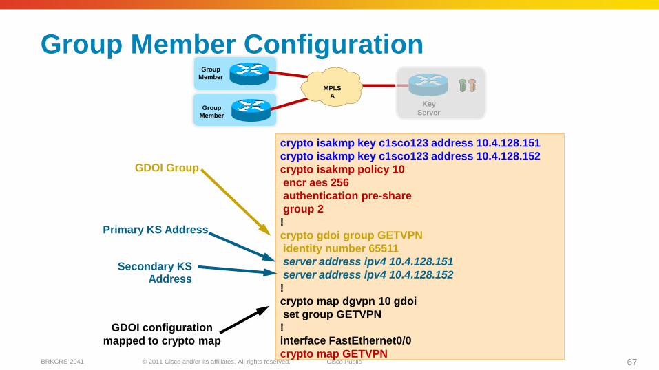
crypto isakmp key c1sco123 address 10.4.128.151
crypto isakmp key c1sco123 address 10.4.128.152
crypto isakmp policy 10
encr aes 256
authentication pre-share
group 2
!
crypto gdoi group GETVPN
identity number 65511
server address ipv4 10.4.128.151
server address ipv4 10.4.128.152
!
crypto map dgvpn 10 gdoi
set group GETVPN
!
interface FastEthernet0/0
crypto map GETVPN
Group Member Configuration
MPLS
A
Key
Server
Group
Member
Group
Member
GDOI Group
Primary KS Address
Secondary KS Address
GDOI configuration
mapped to crypto map

© 2011 Cisco and/or its affiliates. All rights reserved. Cisco PublicBRKCRS-2041 68
crypto keyring gdoi1
pre-shared-key address 0.0.0.0 0.0.0.0 key cisco123
!
crypto isakmp policy 10
encr aes 256
authentication pre-share
group 2
!
crypto ipsec transform-set AES256/SHA esp-aes 256
esp-sha-hmac
!
crypto ipsec profile GETVPN-GDOI-PROFILE
set security-association lifetime seconds 7200
set transform-set AES256/SHA
!
IPSec Profile
IPSec Transform
Key Server Configuration
MPLS
A
Key
Server
Group
Member
Group
Member
© 2011 Cisco and/or its affiliates. All rights reserved. Cisco PublicBRKCRS-2041 69
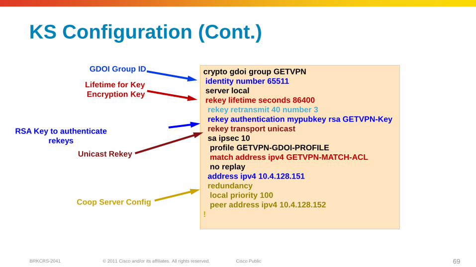
crypto gdoi group GETVPN
identity number 65511
server local
rekey lifetime seconds 86400
rekey retransmit 40 number 3
rekey authentication mypubkey rsa GETVPN-Key
rekey transport unicast
sa ipsec 10
profile GETVPN-GDOI-PROFILE
match address ipv4 GETVPN-MATCH-ACL
no replay
address ipv4 10.4.128.151
redundancy
local priority 100
peer address ipv4 10.4.128.152
!
GDOI Group ID
RSA Key to authenticate
rekeys
Unicast Rekey
Lifetime for Key
Encryption Key
Coop Server Config
KS Configuration (Cont.)
© 2011 Cisco and/or its affiliates. All rights reserved. Cisco PublicBRKCRS-2041 70
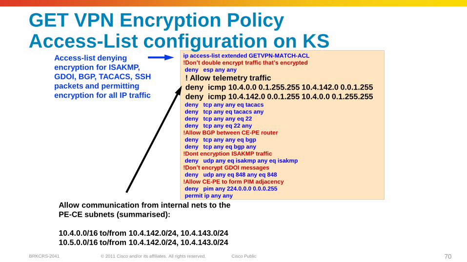
ip access-list extended GETVPN-MATCH-ACL
!Don’t double encrypt traffic that’s encrypted
deny esp any any
! Allow telemetry traffic
deny icmp 10.4.0.0 0.1.255.255 10.4.142.0 0.0.1.255
deny icmp 10.4.142.0 0.0.1.255 10.4.0.0 0.1.255.255deny tcp any any eq tacacs
deny tcp any eq tacacs any
deny tcp any any eq 22
deny tcp any eq 22 any
!Allow BGP between CE-PE router
deny tcp any any eq bgp
deny tcp any eq bgp any
!Dont encryption ISAKMP traffic
deny udp any eq isakmp any eq isakmp
!Don’t encrypt GDOI messages
deny udp any eq 848 any eq 848
!Allow CE-PE to form PIM adjacency
deny pim any 224.0.0.0 0.0.0.255
permit ip any any
Access-list denying
encryption for ISAKMP,
GDOI, BGP, TACACS, SSH
packets and permitting
encryption for all IP traffic
GET VPN Encryption PolicyAccess-List configuration on KS
Allow communication from internal nets to the
PE-CE subnets (summarised):
10.4.0.0/16 to/from 10.4.142.0/24, 10.4.143.0/24
10.5.0.0/16 to/from 10.4.142.0/24, 10.4.143.0/24
© 2011 Cisco and/or its affiliates. All rights reserved. Cisco PublicBRKCRS-2041 71
DMVPN over Internet Deployment
© 2011 Cisco and/or its affiliates. All rights reserved. Cisco PublicBRKCRS-2041 72
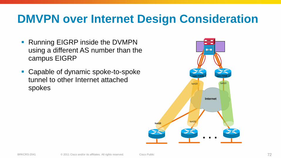
Running EIGRP inside the DVMPNusing a different AS number than the campus EIGRP
Capable of dynamic spoke-to-spoke tunnel to other Internet attached spokes
DMVPN over Internet Design Consideration
. . .
Internet
tun10
tun10tun10
tun10
vpn-7206-1 vpn-7206-2
© 2011 Cisco and/or its affiliates. All rights reserved. Cisco PublicBRKCRS-2041 73
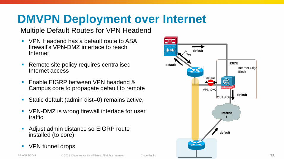
VPN Headend has a default route to ASAfirewall‘s VPN-DMZ interface to reach Internet
Remote site policy requires centralisedInternet access
Enable EIGRP between VPN headend & Campus core to propagate default to remote
Static default (admin dist=0) remains active,
VPN-DMZ is wrong firewall interface for user traffic
Adjust admin distance so EIGRP route installed (to core)
VPN tunnel drops
DMVPN Deployment over Internet
VPN-DMZ
Internet Edge
Block
defaul
t
default
INSIDE
OUTSIDE
default
Internet
default
default
Interne
t
Multiple Default Routes for VPN Headend
© 2011 Cisco and/or its affiliates. All rights reserved. Cisco PublicBRKCRS-2041 74
DMVPN Deployment over Internet
VPN-DMZ
Internet Edge
Block
default
default
INSIDE
OUTSIDE
EIG
R
P
default
Interne
t
default
default
defaul
t
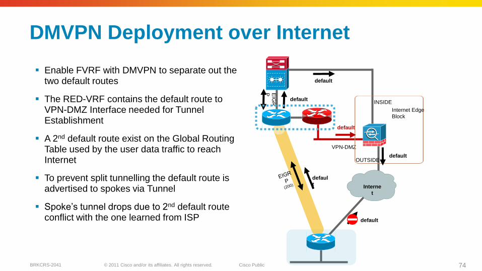
Enable FVRF with DMVPN to separate out the two default routes
The RED-VRF contains the default route to VPN-DMZ Interface needed for Tunnel Establishment
A 2nd default route exist on the Global Routing Table used by the user data traffic to reach Internet
To prevent split tunnelling the default route is advertised to spokes via Tunnel
Spoke‘s tunnel drops due to 2nd default route conflict with the one learned from ISP
© 2011 Cisco and/or its affiliates. All rights reserved. Cisco PublicBRKCRS-2041 75
Interne
t
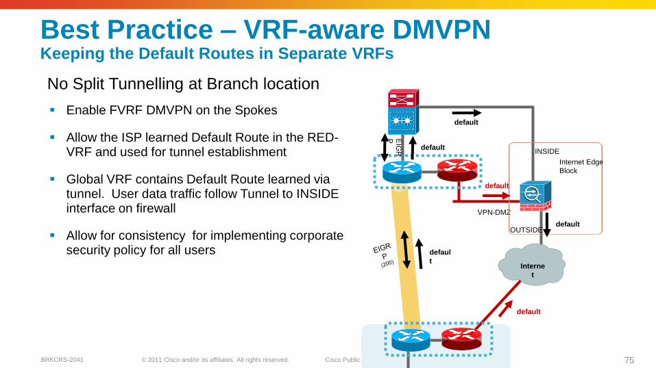
Enable FVRF DMVPN on the Spokes
Allow the ISP learned Default Route in the RED-VRF and used for tunnel establishment
Global VRF contains Default Route learned via tunnel. User data traffic follow Tunnel to INSIDE interface on firewall
Allow for consistency for implementing corporate security policy for all users
Best Practice – VRF-aware DMVPNKeeping the Default Routes in Separate VRFs
VPN-DMZ
Internet Edge
Block
default
default
INSIDE
OUTSIDEdefault
default
defaul
t
No Split Tunnelling at Branch location
EIG
R
P
default
© 2011 Cisco and/or its affiliates. All rights reserved. Cisco PublicBRKCRS-2041 76
Internet
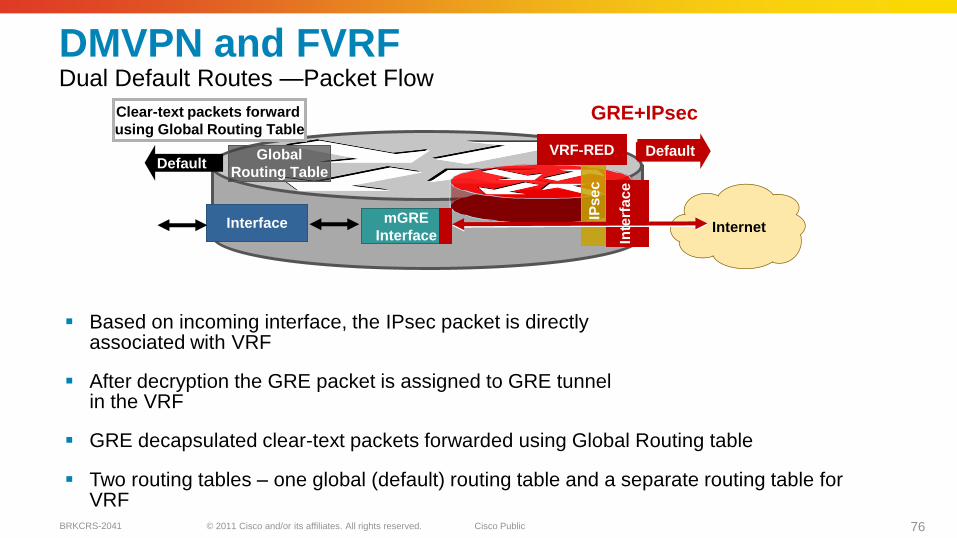
DMVPN and FVRFDual Default Routes —Packet Flow
Based on incoming interface, the IPsec packet is directly associated with VRF
After decryption the GRE packet is assigned to GRE tunnel in the VRF
GRE decapsulated clear-text packets forwarded using Global Routing table
Two routing tables – one global (default) routing table and a separate routing table for VRF
Clear-text packets forward
using Global Routing Table
Interface
IPs
ec
GRE+IPsec
mGRE
Interface
Global
Routing Table
Inte
rfa
ce
DefaultDefaultVRF-RED
© 2011 Cisco and/or its affiliates. All rights reserved. Cisco PublicBRKCRS-2041 77
Internet
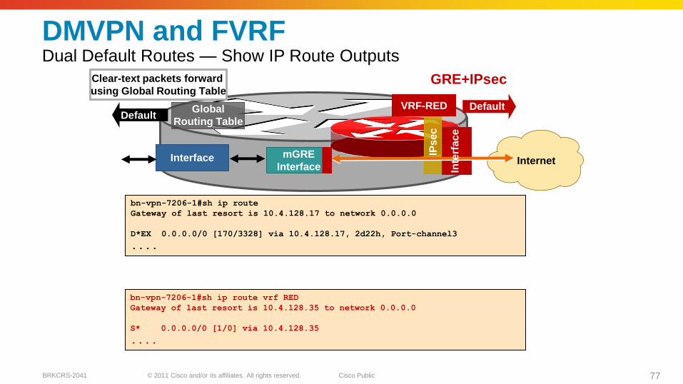
DMVPN and FVRFDual Default Routes — Show IP Route Outputs
Clear-text packets forward
using Global Routing Table
Interface
IPs
ec
GRE+IPsec
mGRE
Interface
Global
Routing Table
Inte
rfa
ce
DefaultDefaultVRF-RED
bn-vpn-7206-1#sh ip route
Gateway of last resort is 10.4.128.17 to network 0.0.0.0
D*EX 0.0.0.0/0 [170/3328] via 10.4.128.17, 2d22h, Port-channel3
....
bn-vpn-7206-1#sh ip route vrf RED
Gateway of last resort is 10.4.128.35 to network 0.0.0.0
S* 0.0.0.0/0 [1/0] via 10.4.128.35
....
© 2011 Cisco and/or its affiliates. All rights reserved. Cisco PublicBRKCRS-2041 78
Internet
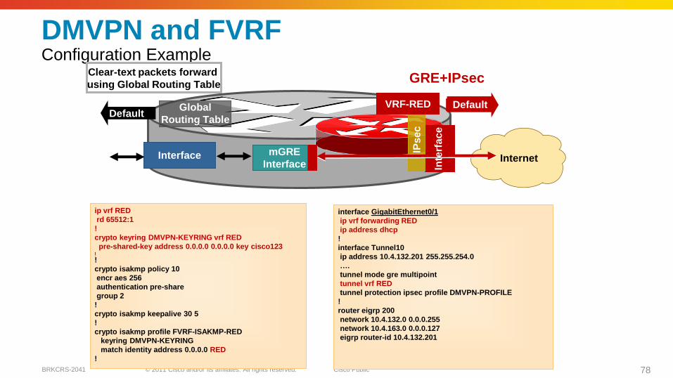
DMVPN and FVRFConfiguration Example
Clear-text packets forward
using Global Routing Table
Interface
IPs
ec
GRE+IPsec
mGRE
Interface
Global
Routing Table
Inte
rfa
ce
DefaultDefaultVRF-RED
ip vrf RED
rd 65512:1
!
crypto keyring DMVPN-KEYRING vrf RED
pre-shared-key address 0.0.0.0 0.0.0.0 key cisco123!!
crypto isakmp policy 10
encr aes 256
authentication pre-share
group 2
!
crypto isakmp keepalive 30 5
!
crypto isakmp profile FVRF-ISAKMP-RED
keyring DMVPN-KEYRING
match identity address 0.0.0.0 RED
!
interface GigabitEthernet0/1
ip vrf forwarding RED
ip address dhcp
!
interface Tunnel10
ip address 10.4.132.201 255.255.254.0
….
tunnel mode gre multipoint
tunnel vrf RED
tunnel protection ipsec profile DMVPN-PROFILE
!
router eigrp 200
network 10.4.132.0 0.0.0.255
network 10.4.163.0 0.0.0.127
eigrp router-id 10.4.132.201
© 2011 Cisco and/or its affiliates. All rights reserved. Cisco PublicBRKCRS-2041 79
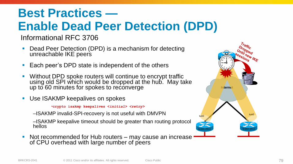
Dead Peer Detection (DPD) is a mechanism for detecting unreachable IKE peers
Each peer‘s DPD state is independent of the others
Without DPD spoke routers will continue to encrypt traffic using old SPI which would be dropped at the hub. May take up to 60 minutes for spokes to reconverge
Use ISAKMP keepalives on spokes•crypto isakmp keepalives <initial> <retry>
–ISAKMP invalid-SPI-recovery is not useful with DMVPN
–ISAKMP keepalive timeout should be greater than routing protocol hellos
Not recommended for Hub routers – may cause an increase of CPU overhead with large number of peers
Best Practices —Enable Dead Peer Detection (DPD)
Internet
br201-2911 br202-2911
tun0tun0
tun10
vpn-7206-1
Informational RFC 3706
© 2011 Cisco and/or its affiliates. All rights reserved. Cisco PublicBRKCRS-2041 80
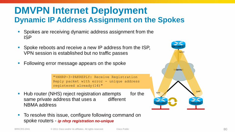
Spokes are receiving dynamic address assignment from the ISP
Spoke reboots and receive a new IP address from the ISP, VPN session is established but no traffic passes
Following error message appears on the spoke
Hub router (NHS) reject registration attempts for the same private address that uses a different NBMA address
To resolve this issue, configure following command on spoke routers - ip nhrp registration no-unique
DMVPN Internet Deployment Dynamic IP Address Assignment on the Spokes
Internet
br201-2911 br202-2911
tun0tun0
tun10
vpn-7206-1
"%NHRP-3-PAKREPLY: Receive Registration
Reply packet with error - unique address
registered already(14)"
© 2011 Cisco and/or its affiliates. All rights reserved. Cisco PublicBRKCRS-2041 81
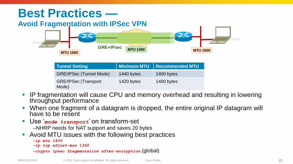
IP fragmentation will cause CPU and memory overhead and resulting in lowering throughput performance
When one fragment of a datagram is dropped, the entire original IP datagram will have to be resent
Use ‗mode transport‘ on transform-set–NHRP needs for NAT support and saves 20 bytes
Avoid MTU issues with the following best practices–ip mtu 1400
–ip tcp adjust-mss 1360
–crypto ipsec fragmentation after-encryption (global)
Best Practices —Avoid Fragmentation with IPSec VPN
MTU 1500MTU 1500MTU 1400
Tunnel Setting Minimum MTU Recommended MTU
GRE/IPSec (Tunnel Mode) 1440 bytes 1400 bytes
GRE/IPSec (Transport
Mode)
1420 bytes 1400 bytes
GRE+IPsec
© 2011 Cisco and/or its affiliates. All rights reserved. Cisco PublicBRKCRS-2041 82
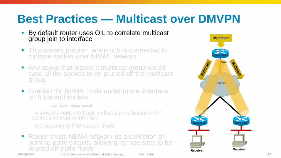
By default router uses OIL to correlate multicast group join to interface
This causes problem when hub is connected to multiple spokes over NBMA network
Any spoke that leaves a multicast group would case all the spokes to be pruned off the multicast group
Enable PIM NBMA mode under tunnel interface on hubs and spokes
• ip pim nbma-mode
–Allows the router to track multicast joins based on IP address instead of interface
–Applies only to PIM sparse-mode
Router treats NBMA network as a collection of point-to-point circuits, allowing remote sites to be pruned off traffic flows
Best Practices — Multicast over DMVPN
Internet
br201-2911 br202-2911
tun10
vpn-7206-1
Multicast
Receiver Receiver
© 2011 Cisco and/or its affiliates. All rights reserved. Cisco PublicBRKCRS-2041 83
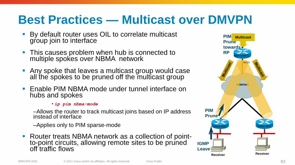
By default router uses OIL to correlate multicast group join to interface
This causes problem when hub is connected to multiple spokes over NBMA network
Any spoke that leaves a multicast group would case all the spokes to be pruned off the multicast group
Enable PIM NBMA mode under tunnel interface on hubs and spokes
• ip pim nbma-mode
–Allows the router to track multicast joins based on IP address instead of interface
–Applies only to PIM sparse-mode
Router treats NBMA network as a collection of point-to-point circuits, allowing remote sites to be pruned off traffic flows
Best Practices — Multicast over DMVPN
Internet
br201-2911 br202-2911
tun10
vpn-7206-1
Receiver Receiver
IGMP
Leave
PIM
Prune
PIM
Prune
towards
RP
Multicast
© 2011 Cisco and/or its affiliates. All rights reserved. Cisco PublicBRKCRS-2041 84
WCCP Implementation Consideration

© 2011 Cisco and/or its affiliates. All rights reserved. Cisco PublicBRKCRS-2041 85
• Implementation and operational consequences?
• Planned Outages? Inline cabling changes are disruptive, WCCP graceful start
• Unplanned failures? Inline simple, fail to wire, WCCP involves configuration changes to the existing infrastructure
• Placement decisions?
• WAN Edge, WAN Distribution, Core, Server Distribution, Server Access
• Redirecting device used depends on placement decision
Design Considerations for WAAS Interception and Redirection Mechanisms
© 2011 Cisco and/or its affiliates. All rights reserved. Cisco PublicBRKCRS-2041 86
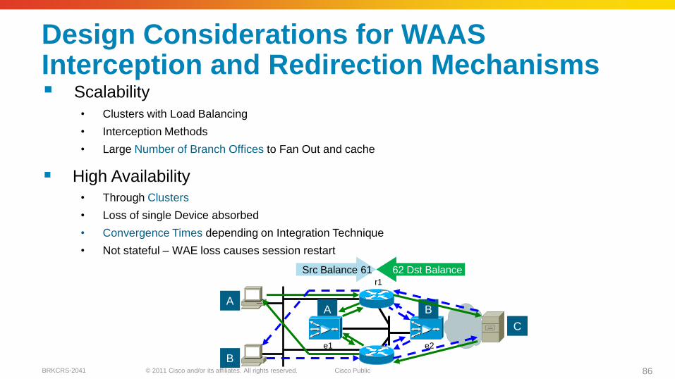
Scalability
• Clusters with Load Balancing
• Interception Methods
• Large Number of Branch Offices to Fan Out and cache
High Availability• Through Clusters
• Loss of single Device absorbed
• Convergence Times depending on Integration Technique
• Not stateful – WAE loss causes session restart
Design Considerations for WAASInterception and Redirection Mechanisms
A
B
A B
C
Src Balance 61 62 Dst Balance
e1 e2
r1
© 2011 Cisco and/or its affiliates. All rights reserved. Cisco PublicBRKCRS-2041 87
WAAS Integration Options
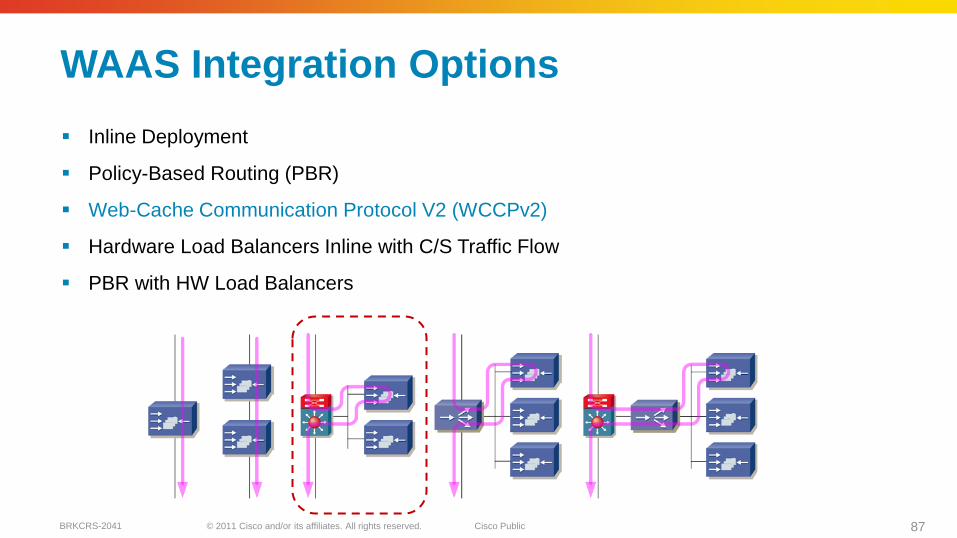
Inline Deployment
Policy-Based Routing (PBR)
Web-Cache Communication Protocol V2 (WCCPv2)
Hardware Load Balancers Inline with C/S Traffic Flow
PBR with HW Load Balancers
© 2011 Cisco and/or its affiliates. All rights reserved. Cisco PublicBRKCRS-2041 88
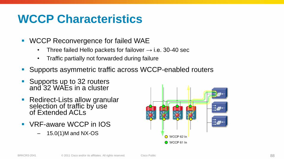
WCCP Reconvergence for failed WAE
• Three failed Hello packets for failover → i.e. 30-40 sec
• Traffic partially not forwarded during failure
Supports asymmetric traffic across WCCP-enabled routers
Supports up to 32 routers and 32 WAEs in a cluster
Redirect-Lists allow granular selection of traffic by use of Extended ACLs
VRF-aware WCCP in IOS
– 15.0(1)M and NX-OS
WCCP Characteristics
© 2011 Cisco and/or its affiliates. All rights reserved. Cisco PublicBRKCRS-2041 89
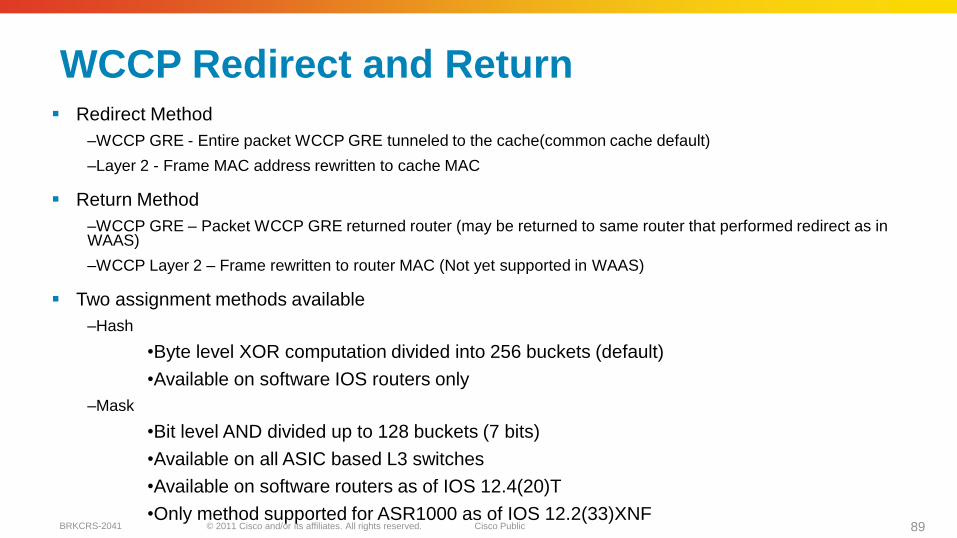
WCCP Redirect and Return Redirect Method
–WCCP GRE - Entire packet WCCP GRE tunneled to the cache(common cache default)
–Layer 2 - Frame MAC address rewritten to cache MAC
Return Method
–WCCP GRE – Packet WCCP GRE returned router (may be returned to same router that performed redirect as in WAAS)
–WCCP Layer 2 – Frame rewritten to router MAC (Not yet supported in WAAS)
Two assignment methods available
–Hash
•Byte level XOR computation divided into 256 buckets (default)
•Available on software IOS routers only
–Mask
•Bit level AND divided up to 128 buckets (7 bits)
•Available on all ASIC based L3 switches
•Available on software routers as of IOS 12.4(20)T
•Only method supported for ASR1000 as of IOS 12.2(33)XNF

© 2011 Cisco and/or its affiliates. All rights reserved. Cisco PublicBRKCRS-2041 90
Single Carrier Branch
WCCP intercepted in from client AND in from server
Services balance on source from client and destination from server to maintain flow symmetry
E1 spoofs C1 to S1
S1 replies to C1
E1 spoofs S1 to C1
E1 must use WCCP GRE return to avoid loops when placed on client network
C1
S1
E1
R1SG 61 In SG 62 In
WAN
© 2011 Cisco and/or its affiliates. All rights reserved. Cisco PublicBRKCRS-2041 91
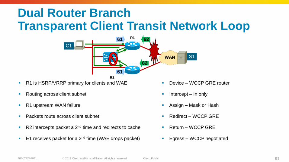
Dual Router BranchTransparent Client Transit Network Loop
R1 is HSRP/VRRP primary for clients and WAE
Routing across client subnet
R1 upstream WAN failure
Packets route across client subnet
R2 intercepts packet a 2nd time and redirects to cache
E1 receives packet for a 2nd time (WAE drops packet)
Device – WCCP GRE router
Intercept – In only
Assign – Mask or Hash
Redirect – WCCP GRE
Return – WCCP GRE
Egress – WCCP negotiated
C1
S1
E1
R1
R2
6261
61
62
WAN
© 2011 Cisco and/or its affiliates. All rights reserved. Cisco PublicBRKCRS-2041 92
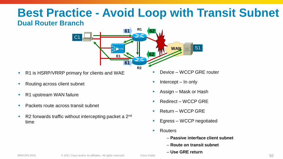
Best Practice - Avoid Loop with Transit SubnetDual Router Branch
R1 is HSRP/VRRP primary for clients and WAE
Routing across client subnet
R1 upstream WAN failure
Packets route across transit subnet
R2 forwards traffic without intercepting packet a 2nd
time
Device – WCCP GRE router
Intercept – In only
Assign – Mask or Hash
Redirect – WCCP GRE
Return – WCCP GRE
Egress – WCCP negotiated
Routers
– Passive interface client subnet
– Route on transit subnet
– Use GRE return
C1
S1
E1
R1
R2
6261
62
61
WAN

© 2011 Cisco and/or its affiliates. All rights reserved. Cisco PublicBRKCRS-2041 93
Summary
© 2011 Cisco and/or its affiliates. All rights reserved. Cisco PublicBRKCRS-2041 94
Key Takeaways
Understand how WAN characteristics can affect your applications
–Bandwidth, latency, loss
Dual carrier designs can provide resiliency but have unique design considerations
A QoS-enabled, highly-available network infrastructure is the foundation layer of the WAN architecture
Encryption is a foundation component of all WAN designs and can be deployed transparently
Understand the how to apply WCCPv2 in the branch network to enable WAN optimisation appliances.

© 2011 Cisco and/or its affiliates. All rights reserved. Cisco PublicBRKCRS-2041 95
Q & A
© 2011 Cisco and/or its affiliates. All rights reserved. Cisco PublicBRKCRS-2041 96
Complete Your Online Session Evaluation
Complete your session evaluation:
Directly from your mobile device by visiting www.ciscoliveaustralia.com/mobile and login by entering your badge ID (located on the front of your badge)
Visit one of the Cisco Live internet stations located throughout the venue
Open a browser on your own computer to access the Cisco Live onsite portal