EN W415-1351 / 08.29.14 FR PG 65 INSTALLER: LEAVE THIS MANUAL WITH THE APPLIANCE. CONSUMER: RETAIN THIS MANUAL FOR FUTURE REFERENCE. NEVER LEAVE CHILDREN OR OTHER AT RISK INDIVIDUALS ALONE WITH THE APPLIANCE INSTALLATION AND OPERATING INSTRUCTIONS Wolf Steel Ltd., 24 Napoleon Rd., Barrie, ON, L4M 0G8 Canada / 103 Miller Drive, Crittenden, Kentucky, USA, 41030 Phone (705)721-1212 • Fax (705)722-6031 • www.napoleonfireplaces.com • [email protected]1.28E $10.00 HOT GLASS WILL CAUSE BURNS. DO NOT TOUCH GLASS UNTIL COOLED. NEVER ALLOW CHILDREN TO TOUCH GLASS. ! WARNING A barrier designed to reduce the risk of burns from the hot viewing glass is provided with the appliance and shall be installed. SAFETY INFORMATION ! WARNING - Do not store or use gasoline or other flammable vapors and liquids in the vicinity of this or any other appliance. - WHAT TO DO IF YOU SMELL GAS: • Do not try to light any appliance. • Do not touch any electrical switch; do not use any phone in your building. • Immediately call your gas supplier from a neighbour’s phone. Follow the gas supplier’s instructions. • If you cannot reach your gas supplier, call the fire department. - Installation and service must be performed by a qualified installer, service agency or the supplier. This appliance may be installed in an aftermarket, permanently located, manufactured home (USA only) or mobile home, where not prohibited by local codes. This appliance is only for use with the type of gas indicated on the rating plate. This appliance is not convertible for use with other gases, unless a certified kit is used. If the information in these instructions are not followed exactly, a fire or explosion may result causing property damage, personal injury or loss of life. CERTIFIED FOR CANADA AND UNITED STATES USING ANSI/CSA METHODS. Decorative Product: Not for use as a heating appliance. BARRIER CONFORMS TO AMERICAN NATIONAL STANDARDS: ANSI Z21.50, CERTIFIED TO CANADIAN CSA 2.22 FOR VENTED GAS FIREPLACES. GD19-1N NATURAL GAS GD19-1P PROPANE SAFETY BARRIER SHOWN WITH VITTORIA FRONT
Transcript
EN
W415-1351 / 08.29.14
FRPG65
INSTALLER: LEAVE THIS MANUAL WITH THE APPLIANCE.CONSUMER: RETAIN THIS MANUAL FOR FUTURE REFERENCE.
NEVER LEAVE CHILDREN OR OTHER AT RISK INDIVIDUALS ALONE WITH THE APPLIANCE
INSTALLATION AND OPERATING INSTRUCTIONS
Wolf Steel Ltd., 24 Napoleon Rd., Barrie, ON, L4M 0G8 Canada / 103 Miller Drive, Crittenden, Kentucky, USA, 41030
A barrier designed to reduce the risk of burns from the hot viewing glass is provided with the appliance and
shall be installed.
SAFETY INFORMATION
! WARNING
- Do not store or use gasoline or other fl ammable vapors and liquids in the vicinity of this or any other appliance.- WHAT TO DO IF YOU SMELL GAS:• Do not try to light any appliance.• Do not touch any electrical switch; do not use
any phone in your building.• Immediately call your gas supplier from a
neighbour’s phone. Follow the gas supplier’s instructions.
• If you cannot reach your gas supplier, call the fi re department.
- Installation and service must be performed by a qualifi ed installer, service agency or the supplier.This appliance may be installed in an aftermarket, permanently located, manufactured home (USA only) or mobile home, where not prohibited by local codes.
This appliance is only for use with the type of gas indicated on the rating plate. This appliance is not convertible for use with other gases, unless a certifi ed kit is used.
If the information in these instructions are not followed exactly, a fi re or explosion may result causing property damage, personal injury or loss of life.
CERTIFIED FOR CANADA AND UNITED STATES USING ANSI/CSA METHODS.
Decorative Product: Not for use as a heating appliance.
BARRIER
CONFORMS TO AMERICAN NATIONAL STANDARDS: ANSI Z21.50, CERTIFIED TO CANADIAN CSA 2.22 FOR VENTED GAS FIREPLACES.
GD19-1NNATURAL GAS
GD19-1PPROPANE
SAFETY BARRIER
SHOWN WITH VITTORIA FRONT
W415-1351 / 08.29.14
2
EN
NOTE: Changes, other than editorial, are denoted by a vertical line in the margin.
TABLE OF CONTENTS
1.0 INSTALLATION OVERVIEW 32.0 INTRODUCTION 4
2.1 DIMENSIONS 52.2 GENERAL INSTRUCTIONS 62.3 GENERAL INFORMATION 72.4 RATING PLATE INFORMATION 7
3.0 VENTING 83.1 VENTING LENGTHS AND COMPONENTS 83.2 TYPICAL VENT INSTALLATION 93.3 SPECIAL VENT INSTALLATIONS 11
4.2 USING FLEXIBLE VENT COMPONENTS 244.2.1 HORIZONTAL AIR TERMINAL INSTALLATION 244.2.2 VERTICAL AIR TERMINAL INSTALLATION 254.2.3 APPLIANCE VENT CONNECTION 26
4.3 USING RIGID VENT COMPONENTS 264.3.1 HORIZONTAL AIR TERMINAL INSTALLATION 274.3.2 EXTENDED HORIZONTAL AND CORNER AIR TERMINAL INSTALLATION 274.3.3 VERTICAL AIR TERMINAL INSTALLATION 28
4.4 VERTICAL THROUGH EXISTING CHIMNEY 294.5 MOBILE HOME INSTALLATION 304.6 GAS INSTALLATION 314.7 OPTIONAL WALL SWITCH 31
5.0 FRAMING 325.1 MINIMUM CLEARANCE TO COMBUSTIBLES 33
5.1.1 REAR VENT 345.1.2 TOP VENT 34
5.2 MINIMUM CLEARANCE TO COMBUSTIBLE ENCLOSURES 355.3 MINIMUM MANTEL CLEARANCES 365.4 NON-COMBUSTIBLE FACING MATERIAL 36
13.0 REPLACEMENTS 5114.0 OVERVIEW 5215.0 ACCESSORIES 5316.0 VALVE TRAIN ASSEMBLY 5417.0 B19NL LOG BURNER 5518.0 B19NL ROCK BURNER 5619.0 VENTING 5720.0 TROUBLESHOOTING 5821.0 WARRANTY 6122.0 SERVICE HISTORY 6223.0 NOTES 63
NOTE: The camera icon indicates video tutorials are available as additional reference, visit http://www.napoleonfi replaces.com/category/product-support/support-centre/
W415-1351 / 08.29.14
3
EN
1.0 INSTALLATION OVERVIEW
SAFETY BARRIER
Door, see “GLASS DOOR INSTALLATION AND REMOVAL” section.
Front face, see “FRONT FACING AND INSET KIT INSTALLATION” section.
Top vent, see “REAR VENT CONVERSION” section.
Venting, see “VENTING” section.
Blower, see “OPTIONAL BLOWER INSTALLATION” section.
Rating Plate, see “RATING PLATE INFORMATION” section.
Burner, see “BURNER INSTALLATION” section.
W415-1351 / 08.29.14
4
EN
3.2C
! WARNING• THIS APPLIANCE IS HOT WHEN OPERATED AND CAN CAUSE SEVERE BURNS IF CONTACTED.• ANY CHANGES OR ALTERATIONS TO THIS APPLIANCE OR ITS CONTROLS CAN BE DANGEROUS AND IS
PROHIBITED.• Do not operate appliance before reading and understanding operating instructions. Failure to operate appliance
according to operating instructions could cause fi re or injury.• Risk of fi re or asphyxiation do not operate appliance with fi xed glass removed.• Do not connect 110 volts to the control valve.• Risk of burns. The appliance should be turned off and cooled before servicing.• Do not install damaged, incomplete or substitute components.• Risk of cuts and abrasions. Wear protective gloves and safety glasses during installation. Sheet metal edges may
be sharp.• Do not burn wood or other materials in this appliance.• Children and adults should be alerted to the hazards of high surface temperature and should stay away to
avoid burns or clothing ignition.• Young children should be carefully supervised when they are in the same room as the appliance.
Toddlers, young children and others may be susceptible to accidental contact burns. A physical barrier is recommended if there are at risk individuals in the house. To restrict access to an appliance, install an adjustable safety gate to keep toddlers, young children and other at risk individuals out of the room and away from hot surfaces.
• Clothing or other fl ammable material should not be placed on or near the appliance.• Due to high temperatures, the appliance should be located out of traffi c and away from furniture and
draperies.• Ensure you have incorporated adequate safety measure to protect infants/toddlers from touching hot surfaces.• Even after the appliance is out, the glass and/or screen will remain hot for an extended period of time.• Check with your local hearth specialty dealer for safety screens and hearth guards to protect children from hot
surfaces. These screens and guards must be fastened to the fl oor.• Any safety screen, guard or barrier removed for servicing the appliance, must be replaced prior to operating
the appliance.• The appliance is a vented gas-fi red appliance. Do not burn wood or other materials in the appliance• It is imperative that the control compartments, burners and circulating blower and its passageway in the appliance
and venting system are kept clean. The appliance and its venting system should be inspected before use and at least annually by a qualifi ed service person. More frequent cleaning may be required due to excessive lint from carpeting, bedding material, etc. The appliance area must be kept clear and free from combustible materials, gasoline and other fl ammable vapors and liquids.
• Under no circumstances should this appliance be modifi ed.• This appliance must not be connected to a chimney fl ue pipe serving a separate solid fuel burning appliance.• Do not use this appliance if any part has been under water. Immediately call a qualifi ed service technician to inspect
the appliance and to replace any part of the control system and any gas control which has been under water.• Do not operate the appliance with the glass door removed, cracked or broken. Replacement of the glass should be
done by a licensed or qualifi ed service person.• Do not strike or slam shut the appliance glass door.• When equipped with pressure relief doors, they must be kept closed while the appliance is operating to prevent
exhaust fumes containing carbon monoxide, from entering into the home. Temperatures of the exhaust escaping through these openings can also cause the surrounding combustible materials to overheat and catch fi re.
• Only doors / optional fronts certifi ed with the appliance are to be installed on the appliance.• Keep the packaging material out of reach of children and dispose of the material in a safe manner. As with all plastic
bags, these are not toys and should be kept away from children and infants. • As with any combustion appliance, we recommend having your appliance regularly inspected and serviced as well
as having a Carbon Monoxide Detector installed in the same area to defend you and your family against Carbon Monoxide.
• Ensure clearances to combustibles are maintained when building a mantel or shelves above the appliance. Elevated temperatures on the wall or in the air above the appliance can cause melting, discolouration or damage of decorations, a T.V. or other electronic components.
• A barrier designed to reduce the risk of burns from the hot viewing glass is provided with this appliance and shall be installed.
• If the barrier becomes damaged, the barrier shall be replaced with the manufacturer’s barrier for this appliance.
• Installation and repair should be done by a qualifi ed service person. The appliance should be inspected before use and at least annually by a professional service person. More frequent cleaning may be required due to excessive lint from carpeting, bedding material, etc. It is imperative that control compartments, burners and circulating air passageways of the appliance be kept clean.
2.0 INTRODUCTION
W415-1351 / 08.29.14
5
EN
34 1/8"867mm
12"305mm
GAS LINEACCESS
15 3/8"391mm
ELECTRICAL ACCESS
21 3/4"552mm
19 3/4"502mm
7 "178mm
4 "102mm
34 1/8"867mm
1 3/4"45mm
2 1/2"64mm
5"127mm
9 1/2"241mm
9 "229mm 7 "
178mm4 "
102mm
26 3/8"670mm
13"330mm
20 1/2"521mm
19 3/4"502mm
33 1/8"841mm
33 7/8"860mm
12"305mm
13"330mm
GAS LINEACCESS
ELECTRICAL ACCESS
2.1 DIMENSIONS
W415-1351 / 08.29.14
6
EN
2.2 GENERAL INSTRUCTIONS
4.1B
THIS GAS APPLIANCE SHOULD BE INSTALLED AND SERVICED BY A QUALIFIED INSTALLER to conform with local codes. Installation practices vary from region to region and it is important to know the specifi cs that apply to your area, for example in Massachusetts State: • This product must be installed by a licensed plumber or gas fi tter when installed within the commonwealth
of Massachusetts.• The appliance damper must be removed or welded in the open position prior to installation of an appliance
insert or gas log.• The appliance off valve must be a “T” handle gas cock.• The fl exible connector must not be longer than 36 inches (914mm).• A Carbon Monoxide detector is required in all rooms containing gas fi red appliances.• The appliance is not approved for installation in a bedroom or bathroom unless the unit is a direct vent
sealed combustion product.
The installation must conform with local codes or, in absence of local codes, the National Gas and Propane Installation Code CSA B149.1 in Canada, or the National Fuel Gas Code, ANSI Z223.1 / NFPA 54 in the United States. Suitable for mobile home installation if installed in accordance with the current standard CAN/CSA Z240MH Series, for gas equipped mobile homes, in Canada or ANSI Z223.1 and NFPA 54 in the United States.
As long as the required clearance to combustibles is maintained, the most desirable and benefi cial location for an appliance is in the center of a building, thereby allowing the most effi cient use of the heat created. The location of windows, doors and the traffi c fl ow in the room where the appliance is to be located should be considered. If possible, you should choose a location where the vent will pass through the house without cutting a fl oor or roof joist.
If the appliance is installed directly on carpeting, vinyl tile or other combustible material other than wood fl ooring, the appliance shall be installed on a metal or wood panel extending the full width and depth.
Some appliances have optional fans or blowers. If an optional fan or blower is installed, the junction box must be electrically connected and grounded in accordance with local codes, use the current CSA C22.1 Canadian Electrical Code in Canada or the ANSI/NFPA 70 National Electrical code in the United States.
We suggest that our gas hearth products be installed and serviced by professionals who are certified in the U.S. by the National Fireplace Institute® (NFI) as NFI Gas Specialists
www.nficertified.org
ALWAYS LIGHT THE PILOT WHETHER FOR THE FIRST TIME OR IF THE GAS SUPPLY HAS RUN OUT, WITH THE GLASS DOOR OPENED OR REMOVED.
PROVIDE ADEQUATE CLEARANCE FOR SERVICING AND OPERATING THE APPLIANCE. PROVIDE ADEQUATE VENTILATION.
NEVER OBSTRUCT THE FRONT OPENING OF THE APPLIANCE.OBJECTS PLACED IN FRONT OF THE APPLIANCE MUST BE KEPT A MINIMUM OF 48” (1219mm) FROM
THE FRONT FACE OF THE APPLIANCE.SURFACES AROUND AND ESPECIALLY ABOVE THE APPLIANCE CAN BECOME HOT. AVOID CONTACT
WHEN THE APPLIANCE IS OPERATING.FIRE RISK. EXPLOSION HAZARD.
HIGH PRESSURE WILL DAMAGE VALVE. DISCONNECT GAS SUPPLY PIPING BEFORE PRESSURE TESTING GAS LINE AT TEST PRESSURES ABOVE 1/2 PSIG. CLOSE THE MANUAL SHUT-OFF VALVE BEFORE PRESSURE
TESTING GAS LINE AT TEST PRESSURES EQUAL TO OR LESS THAN 1/2 PSIG (35 mb).USE ONLY WOLF STEEL APPROVED OPTIONAL ACCESSORIES AND REPLACEMENT PARTS WITH THIS APPLIANCE.
USING NON-LISTED ACCESSORIES (BLOWERS, DOORS, LOUVRES, TRIMS, GAS COMPONENTS, VENTING COMPONENTS, ETC.) COULD RESULT IN A SAFETY HAZARD AND WILL VOID THE WARRANTY AND CERTIFICATION.
! WARNING
W415-1351 / 08.29.14
7
EN
2.3 GENERAL INFORMATION
* When the appliance is installed at elevations above 4,500ft (1372m), and in the absence of specifi c recommendations from the local authority having jurisdiction, the certifi ed high altitude input rating shall be reduced at the rate of 4% for each additional 1,000ft (305m) .
Expansion / contraction noises during heating up and cooling down cycles are normal and to be expected.
This appliance is only for use with the type of gas indicated on the rating plate. This appliance is not convertible for use with other gases, unless a certifi ed kit is used.
Provide adequate accessibility clearance for servicing and operating the appliance.
Never obstruct the front opening of the appliance.
A barrier designed to reduce the risk of burns from the hot viewing glass is provided with the appliance and shall be installed.
FOR YOUR SATISFACTION, THIS APPLIANCE HAS BEEN TEST-FIRED TO ASSURE ITS OPERATION AND QUALITY!
RATES AND EFFICIENCIESNATURAL GAS PROPANE GAS
Altitude 0 - 4,500* 0 - 4,500*Maximum Input 11,500 11,000Maximum Output 8,600 8,250Effi ciency 75% 75%Minimum Inlet Gas Supply Pressure 4.5" (11mb) Water Column 11" (27mb) Water ColumnMaximum Inlet Gas Supply Pressure 7" (17mb) Water Column 13" (32mb) Water ColumnManifold Pressure Under Flow Conditions 3.5" (9mb) Water Column 10" (25mb Water Column
2.4 RATING PLATE INFORMATION
W385-1976
NOT FOR USE WITH SOLID FUEL
GD19
GD19NNATURAL GAS MODEL
CONFORMS TO / CONFORME AUX: ANSI Z21.50-2014, CERTIFIED TO / CERTIFIE CSA 2.22-2014 VENTED GAS FIREPLACE / FOYER À GAZ VENTILÉ.DIRECT VENT VENTED GAS FIREPLACE APPROVED FOR BEDROOM, BATHROOM & BEDSITTING ROOM INSTALLATION. SUITABLE FOR MOBILE HOME INSTALLATION IF INSTALLED IN ACCORDANCE WITH THE CURRENT STANDARD CAN/CSA Z240MH SERIES GAS EQUIPPED MOBILE HOMES, IN CANADA OR IN THE UNITED STATES THE MANUFACTURED HOME CONSTRUCTION AND SAFETY STANDARD, TITLE 24 CFR, PART 3280. WHEN THIS US STANDARD IS NOT APPLICABLE USE THE STANDARD FOR FIRE SAFETY CRITERIA FOR MANUFACTURED HOME INSTALLATIONS, SITES AND COMMUNITIES, ANSI / NFPA 501A.
FOYER À GAZ VENTILÉS À ÉVACUATION DIRECTE. HOMOLOGUE POUR INSTALLATION DANS UNE CHAMBRE A COUCHER, UNE SALLE DE BAIN ET UN STUDIO. APPROPRIE POUR INSTALLATION DANS UNE MAISON MOBILE SI SON INSTALLATION
CONFORME AUX EXIGENCES DE LA NORME CAN/CSA Z240MH SERIE DE MAISONS MOBILES EQUIPEES AU GAZ, EN VIGUEUR AU CANADA OU AUX ETATS-UNIS DE LA NORME DE SECURITE ET DE CONSTRUCTION DE MAISONS
MANUFACTUREES, TITRE 24 CFR, SECTION 3280. DANS LE CAS OU CETTE NORME D'ETATS-UNIS NE PEUT ETRE APPLIQUEE, SE REFERER A LA NORME RELATIVE AU CRITERE DE MESURES DE SECURITE CONTRE L'INCENDIE POUR
LES INSTALLATIONS DANS LES MAISONS MANUFACTURES, LES SITES ET LES COMMUNAUTES, ANSI/NFPA 501A.
MANIFOLD PRESSURE: 3.5 INCHES W.C. (NG)
PRESSION AU COLLECTEUR: 3.5" D'UNE COLONNE D'EAU(GN)
MIN SUPPLY PRESSURE: 4.5" W.C.(NG)PRESSION D'ALIMENTATION MIN: 4.5" D'UNE
PRESSION D'ALIMENTATION MAX: 7" D'UNE COLONNE D'EAU (GN)
MANIFOLD PRESSURE: 10 INCHES W.C.(LP)PRESSION AU COLLECTEUR: 10" D'UNE COLONNE D'EAU (P)MIN SUPPLY PRESSURE: 11" W.C. (LP)PRESSION D'ALIMENTATION MIN: 11" D'UNE COLONNE D'EAU (P)MAX. SUPPLY PRESSURE: 13" W.C. (LP)PRESSION D'ALIMENTATION MAX: 13" D'UNE COLONNE D'EAU (P)
0-4500ft11,500 BTU/h8,000 BTU/h
55.9%
ALTITUDE / ELEVATIONINPUT / ALIMENTATION
REDUCED INPUT /ALIMENTATION REDUITE
P4FOR USE WITH GLASS DOORS CERTIFIED WITH THIS UNIT ONLY. FOR USE ONLY WITH BARRIER W565-0170. FOLLOW THE INSTALLATION INSTRUCTIONS LOCATED IN THE INSTALLATION MANUAL. WARNING: DO NOT ADD ANY MATERIAL TO THE APPLIANCE, WHICH WILL COME IN CONTACT WITH THE FLAMES, OTHER THAN THAT SUPPLIED BY THE MANUFACTURER WITH THE APPLIANCE.THIS VENTED GAS FIREPLACE IS NOT FOR USEWITH AIR FILTERS.ELECTRICAL RATING: BLOWER KIT GS66, 115V 0.5AMP 60HZ THE APPLIANCE MUST BE VENTED USING THE APPROPRIATE WOLF STEEL VENT KITS. SEE OWNERS INSTALLATION MANUAL FOR VENTING SPECIFICS. MINIMUM AND MAXIMUM VERTICAL VENT LENGTHS ARE 3 FEET AND 35FEET RESPECTIVELY.
MINIMUM AND MAXIMUM HORIZONTAL VENTLENGTHS ARE 8 INCHES AND 20 FEETRESPECTIVELY. PROPER REINSTALLATION AND RESEALING IS NECESSARY AFTER SERVICING THE VENT-AIR INTAKE SYSTEM.DECORATIVE PRODUCT: NOT FOR USE AS A HEATING APPLIANCE
MINIMUM CLEARANCE TO COMBUSTIBLE MATERIAL:
UTILISER AVEC LES PORTES VITREES HOMOLOGUEES SEULEMENT AVEC CETTE UNITE. POUR UNE UTILISER SEULMENT AVEC BARRIÈRE W565-0170. SUIVEZ LES INSTRUCTIONS D'INSTALLATION SE TROUVENT DANS LE MANUEL D'INSTALLATION. AVERTISSEMENT: N'AJOUTEZ PAS A CET APPAREILAUCUN MATERIAU DEVANT ENTRER EN CONTACT AVEC LES FLAMMES AUTRE QUE CELUI QUI EST FOURNI AVEC CET APPAREIL PAR LE FABRICANT. CE FOYER À GAZ VENTILÉS NE DOIT PAS ÊTRE UTILISÉ CONJOINTEMENT AVEC DES FILTRES À AIR.CLASS: SOUFFLERIE GS66, 115V 0.5AMP 60HZ L'APPAREIL DOIT EVACUER SES GAZ EN UTILISANT L'ENSEMBLE D'EVACUATION PROPRE A WOLF STEEL. REFERER AU MANUEL D'INSTALLATION DE PROPRIETAIRE POUR L'EVACUATION PRECISE. LES LONGUEURS VERTICALES MINIMALES ET MAXIMALES SONT3 PIEDS ET 35 PIEDS RESPECTIVEMENT.
UN COMBUSTIBLE SOLIDE NE DOIT PAS ETRE UTILSE AVEC CET APPAREIL
LES LONGUEURS HORIZONTALES MINIMALES ET MAXIMALES SONT 8 POUCES ET 20 PIEDS RESPECTIVEMENT. IL EST IMPORTANT DE BIEN REINSTALLER ET RESCELLER L'EVENT APRES AVOIR ASSURE LE MAINTIEN DU SYSTEME DE PRISE D'AIR.PRODUIT DÉCORATIF: NE PAS UTILISER COMME APPAREIL DE CHAUFFAGE.DEGAGEMENTS MINIMAUX DES MATERIAUX COMBUSTIBLES:
DESSUS 0" MANTEAU 2"* PLANCHER 0" PROFONDEUR DE L’ENCLAVE 13"COTES 0" ÉVENT 1”ARRIÉRE 0” TOP, SIDES & BACK: PER STAND OFF SPACERS
FOR FRAMING MATERIALS. FOR FINISHING MATERIALS SEE OWNERS MANUAL. DESSUS, COTES & ARRIERE: SELON LES ESPACEURS DE
DEGAGEMENT POUR LES MATERIAUX D’OSSATURE SELON LE MANUEL DE PROPRIETAIRE POUR LES MATERIAUX DE FINITION.
* MAXIMUM HORIZONTAL EXTENSION 2”. SEE INSTRUCTION MANUAL FOR GREATER EXTENSIONS.* L’EXTENSION HORIZONTAL MAXIMALE 2”. REFERER AU MANUEL D’INSTRUCTION POUR DES EXTENSIONS PLUS GRANDES.
PROPANE MODEL
WOLF STEEL LTD.24 NAPOLEON ROAD, BARRIE, ON, L4M 0G8 CANADA
RATING PLATE LOCATION: The rating label is located behind the control panel and is chained to the appliance. DO NOT REMOVE.
This illustration is for reference only. Refer to the rating plate on the appliance for accurate information.
NOTE: The rating plate must remain with the appliance at all times. It must not be removed.
SAMPLETION DIR
DIO. APPRNCES DE LA NORME
CANADA OU AUX ETATSEES, TITRE 24 CFR, SECTION 3280
ER A LA NORME RELATIVE AU CRDANS LES MAISONS MANU
EVATIONMENTATION
CED INPUATION REDUITE
P4
T
ATION AND R SERVICING
R USE AS A HEATING
CE TO COMBUSTIBLE MATERIAL
LISER AVEC HOMOLOGUEES SUNITE OUR UNBARRIÈRE W5
'INSTALLD'INSTAVA
0-4500ft 11,000
GD19P
PL MANTEL 2"* RECESSED DEPTH 13"
VENT 1
P, SIDES & BACK: PER STAND OOR FRAMING MATERIALS. FOR FIN
MATERIALS SEE OWNERS MANUA
UAL FOR GRE
OPANE M
0164001659
W415-1351 / 08.29.14
8
EN
3.0 VENTING
7.1C
THIS APPLIANCE USES A 4” (102mm) EXHAUST / 7” (178mm) AIR INTAKE VENT PIPE SYSTEM.Refer to the section applicable to your installation.
For safe and proper operation of the appliance follow the venting instruction exactly. Deviation from the minimum vertical vent length can create diffi culty in burner start-up and/or carboning. Under extreme vent confi gurations, allow several minutes (5-15) for the fl ame to stabilize after ignition. Although not a requirement, it is recommended for vent lengths that pass through unheated spaces (attics, garages, crawl spaces) be insulated with the insulation wrapped in a protective sleeve to minimize condensation. Provide a means for visually checking the vent connection to the appliance after the appliance is installed. Use a fi restop, vent pipe shield or attic insulation shield when penetrating interior walls, fl oor or ceiling.NOTE: If for any reason the vent air intake system is disassembled; reinstall per the instructions provided for the initial installation.
! WARNINGRISK OF FIRE, MAINTAIN SPECIFIED AIR SPACE CLEARANCES TO VENT PIPE AND APPLIANCE.
IF VENTING IS INCLUDED WITH SPACERS THE VENT SYSTEM MUST BE SUPPORTED EVERY 3FT (0.9m) FOR BOTH VERTICAL AND HORIZONTAL RUNS. USE SUPPORTS OR EQUIVALENT
NON-COMBUSTIBLE STRAPPING TO MAINTAIN THE REQUIRED CLEARANCE FROM COMBUSTIBLES. USE WOLF STEEL LTD. SUPPORT RING ASSEMBLY W010-0370 OR EQUIVALENT NON-COMBUSTIBLE STRAPPING TO MAINTAIN THE MINIMUM CLEARANCE TO COMBUSTIBLES
FOR BOTH VERTICAL AND HORIZONTAL RUNS. SPACERS ARE ATTACHED TO THE INNER PIPE AT PREDETERMINED INTERVALS TO MAINTAIN AN EVEN AIR GAP TO THE OUTER PIPE. THIS GAP IS REQUIRED FOR SAFE OPERATION. A SPACER IS REQUIRED AT THE START, MIDDLE AND END OF EACH ELBOW TO ENSURE THIS GAP IS MAINTAINED. THESE SPACERS MUST NOT BE REMOVED.
3.1 VENTING LENGTHS AND COMPONENTSUse only Wolf Steel, Simpson Dura-Vent, Selkirk Direct Temp, American Metal Amerivent or Metal-Fab venting components. Minimum and maximum vent lengths, for both horizontal and vertical installations, and air terminal locations for either system are set out in this manual and must be adhered to. For Simpson Dura-Vent, Selkirk Direct Temp, American Metal Amerivent and Metal-Fab follow the installation procedure provided with the venting components.
A starter adaptor must be used with the following vent systems and may be purchased from the corresponding supplier:
For Simpson Dura-Vent, Selkirk Direct Temp, American Metal Amerivent and Metal-Fab follow the installation procedure found on the website for your venting supplier.
For vent systems that provide seals on the inner exhaust fl ue, only the outer air intake joints must be sealed using a red high temperature silicone (RTV). This same sealant may be used on both the inner exhaust and outer intake vent pipe joints of all other approved vent systems except for the exhaust vent pipe connection to the appliance fl ue collar which must be sealed using the black high temperature sealant Mill Pac. High temperature sealant must be ordered separately.
When using Wolf Steel venting components, use only approved Wolf Steel rigid / fl exible components with the following termination kits: wall terminal kit GD222, GD222R, or 1/12 to 7/12 pitch roof terminal kit GD110, 8/12 to 12/12 roof terminal kit GD111, fl at roof terminal kit GD112 or periscope kit GD201 (for wall penetration below grade). With fl exible venting, in conjunction with the various terminations, use either the 5 foot (1.5m) vent kit GD220 or the 10 foot (3.1m) vent kit GD330.
PART 4”/7” SUPPLIER WEBSITE
Duravent W175-0053 Wolf Steel www.duravent.com
Amerivent 4DSC-N2 American Metal www.americanmetalproducts.com
Direct Temp 4DT-AAN Selkirk www.selkirkcorp.com
SuperSeal 4DNA Metal-Fab www.mtlfab.com
W415-1351 / 08.29.14
9
EN
For optimum flame appearance and appliance performance, keep the vent length and number of elbows to a minimum. The air terminal must remain unobstructed at all times. Examine the air terminal at least once a year to verify that it is unobstructed and undamaged.Rigid and fl exible venting systems must not be combined. Different venting manufacturer components must not be combined.
These vent kits allow for either horizontal or vertical venting of the appliance. The maximum allowable horizontal run is20 feet (6.1m). The maximum allowable vertical vent length is 40 feet (12.2m). The maximum number of vent connections is two horizontally or three vertically (excluding the appliance and the air terminal connections) when using fl exible venting.
8.1A
3.2 TYPICAL VENT INSTALLATION
16” (406mm) MINIMUM
35 FT (11M)MAXIMUM
3 FT (1M) MINIMUM
33 1/8" (841MM)
43 1/8" (1095MM) MINIMUM
PLUS RISE*
10" (254MM)MINIMUM
24” (610MM)MAXIMUM
* See "VENTING" section
33 1/8" (841MM)
W415-1351 / 08.29.14
10
EN
26 3/8" (670MM)
26 3/8" (670MM) MINIMUM
PLUS RISE*
20" (508MM) MAXIMUM
* See "VENTING" section
35 FT (11M)MAXIMUM
3 FT (1M) MINIMUM
16” (406MM) MINIMUM
W415-1351 / 08.29.14
11
EN
3.3 SPECIAL VENT INSTALLATIONS3.3.1 PERISCOPE TERMINATION
24" (610MM) MINIMUM
Use the periscope kit to locate the air termination above grade. The periscope must be installed so that when fi nal grading is completed, the bottom air slot is located a minimum 12” (304.8mm) above grade. The maximum allowable vent length is 10’ (3.1m) for a fi replace and 8’ (2.4m) for a stove.
9.4A
12" (305MM) MINIMUM
TO GRADE
33 1/8" (841MM)
20” (508mm) MAXIMUM
6” (152.4mm)RISE
3.3.2 CORNER TERMINATIONThe maximum vent length for a corner installation is 20" (508mm) of horizontal run, in addition to the 45° offset. In this case zero rise is acceptable. See illustrations below. It is recommended to maintain a 6" (152mm) rise.
24" (610MM) MINIMUM
12" (305MM) MINIMUM
TO GRADE
W415-1351 / 08.29.14
12
EN
3.4 VENT TERMINAL CLEARANCES
INSTALLATIONSCANADA U.S.A.
A 12” (304.8mm) 12” (304.8mm) Clearance above grade, veranda porch, deck or balcony.
B 12” (304.8mm) Δ 9” (228.6mm)Δ Clearance to windows or doors that open.
C 12” (304.8mm)*
12” (304.8mm)* Clearance to permanently closed windows.
D 18” (457.2mm)**
18” (457.2mm)**
Vertical clearance to ventilated soffi ts located above the terminal within a horizontal distance of 2’ (50.8mm) from the centerline of the terminal.
E 18” (457.2mm)**
18” (457.2mm)** Clearance to unventilated soffi t.
F 0” (0mm) 0” (0mm) Clearance to an outside corner wall.
G0” (0mm)*** 0” (0mm)*** Clearance to an inside non-combustible corner wall or protruding non-combustible obstructions (chimney,
etc.).
2” (50.8mm)*** 2” (50.8mm)*** Clearance to an inside combustible corner wall or protruding combustible obstructions (vent chase, etc.).
H 3’ (0.9m) 3’ (0.9m)**** Clearance to each side of the centerline extended above the meter / regulator assembly to a maximum vertical distance of 15’ (4.6m).
I 3’ (0.9m) 3’ (0.9m) **** Clearance to a service regulator vent outlet.
J 12” (304.8mm) 9” (228.6mm) Clearance to a non-mechanical air supply inlet to the building or a combustion air inlet to any other appliance.
K 6’ (1.8m) 3’ (0.9m) † Clearance to a mechanical air supply inlet.
L 7’ (2.1m) ‡ 7’ (2.1m) **** Clearance above a paved sidewalk or paved driveway located on public property.
M 12” (304.8mm)††
12” (304.8mm)**** Clearance under a veranda, porch, deck or balcony.
N 16” (406.4mm) 16” (406.4mm) Clearance above the roof.
O 2’ (0.6m)†* 2’ (0.6m)†* Clearance from an adjacent wall including neighbouring buildings.
P 8’ (2.4m) 8’ (2.4m) Roof must be non-combustible without openings.
Q 3’ (0.9m) 3’ (0.9m) See chart for wider wall dimensions.
R 6’ (1.8m) 6’ (1.8m) See chart for deeper wall dimensions. The terminal shall not be installed on any wall that has an opening between the terminal and the open side of the structure.
Δ In a structure with three walls and a roof, the terminal shall not be located less than 6 feet (1.8m) under a window that opens on a horizontal plane.
* Recommended to prevent condensation on windows and thermal breakage
** It is recommended to use a heat shield and to maximize the distance to vinyl clad soffi ts.
*** The periscope requires a minimum 18” (457.2mm) clearance from an inside corner.
This is a recommended distance. For additional requirements check local codes.
† 3 feet above if within 10 feet (3.1m) horizontally.
‡ A vent shall not terminate where it may cause hazardous frost or ice accumulations on adjacent property surfaces.
†† Permitted only if the veranda, porch, or deck is fully open on a minimum of two sides beneath the fl oor.
†* Recommended to prevent recirculation of exhaust products. For additional requirements check local codes.
12.6CNOTE: Clearances are in accordance with local installation codes and the requirements of the gas supplier.
R
Q M
GP
COVERED BALCONY APPLICATIONS
QMIN R MAX MAXR= 3 feet(0.9m)
= 2 x (4.6m)
QACTUAL
W415-1351 / 08.29.14
13
EN
3.5 VENTING APPLICATION FLOW CHART
13.3A
TOP EXIT
Horizontal Termination Vertical Termination
Vertical rise is equal to or greater than the horizontal run
Vertical rise is less than horizontal run
Vertical rise is equal to or greater than the horizontal run
Vertical rise is less than horizontal run
Horizontal run + vertical rise to maximum of
35 feet (10.7m)
Horizontal run + vertical rise to
maximum of 24.75 feet (7.5m)
Horizontal run + vertical rise to maximum of
35 feet (10.7m)
Horizontal run + vertical rise to maximum of
35 feet (10.7m)
4.2 times the vertical rise equal to or greater than the
horizontal run
3 times the vertical rise equal to or greater than the horizontal run
13.4A
REAR EXIT
Horizontal Termination Vertical Termination
Vertical rise is equal to or greater than the horizontal run
Vertical rise is less than horizontal run
Vertical rise is equal to or greater than the horizontal run
Vertical rise is less than horizontal run
Horizontal run + vertical rise to maximum of
35 feet (10.7m)
Horizontal run + vertical rise to maximum of
24.75 feet (7.5m).
Horizontal run + vertical rise to maximum of
35 feet (10.7m)
Horizontal run + vertical rise to maximum of
35 feet (10.7m)
3.5 times the vertical rise equal to or greater than the
horizontal run
3 times the vertical rise equal to or greater than the horizontal run
3.6 DEFINITIONS
14.1
For the following symbols used in the venting calculations and examples are:> - greater than> - equal to or greater than< - less than< - equal to or less thanHT - total of both horizontal vent lengths (Hr) and offsets (Ho) in feetHR - combined horizontal vent lengths in feetHO - offset factor: .03 (total degrees of offset - 90°*) in feetVT - combined vertical vent lengths in feet
* The fi rst 90° offset has a zero value and is shown in the formula as - 90°
3.8 TOP EXIT HORIZONTAL TERMINATION
(HT) < (VT)
Simple venting configuration (only one 90° elbow) See graph to determine the required vertical rise VT for the required horizontal run HT.
0 2.5 (0.8)
5(1.5)
7.5(2.3)
10(3.1)
12.5(3.8)
15(4.6)
40 (12.2)
10 (3.1)
20 (6.1)
30 (9.1)
17.5(5.3)
20 (6.1)
35 (10.7)
REQUIRED VERTICAL
RISE IN FEET (METERS) VT
HORIZONTAL VENT RUN PLUS OFFSET IN FEET (METERS)HT
For vent configurations requiring more than one 90° elbow, the following formulas apply:Formula 1: HT < VTFormula 2: HT + VT < 35 feet (10.7m)
Example:V1 = 3 FT (0.9m)V2 = 8 FT (2.4m)VT = V1 + V2 = 3 FT (0.9m) + 8 FT (2.4m) = 11 FT (3.4m)H1 = 2.5 FT (0.8m)H2 = 2 FT (0.6m)HR = H1 + H2 = 2.5 FT (0.8m) + 2 FT (0.6m) = 4.5 FT (1.4m)HO = .03 (three 90° elbows - 90°) = .03 (270° - 90°) = 5.4 FT (1.7m)HT = HR + HO = 4.5 FT (1.4m) + 5.4 FT (1.7m) = 9.9 FT (3m)HT + VT = 9.9 FT (3m) + 11 FT (3.4m) = 20.9 FT (6.4m)
Formula 1: HT < VT 9.9 FT (3m) < 11 FT (3.4m)Formula 2: HT + VT < 35 FT (10.7m) 20.9 FT (6.4m) < 35 FT (10.7m)Since both formulas are met, this vent configuration is acceptable.
90°
90°
90°
V1
V2
H1
H2
The shaded area within the lines represents acceptable values for HT and VT
16.6B
W415-1351 / 08.29.14
15
EN
(HT) > (VT)
Simple venting configuration (only one 90° elbow) See graph to determine the required vertical rise VT for the required horizontal run HT.
REQUIRED VERTICAL RISE
IN INCHES (MILLIMETERS)
VT
HORIZONTAL VENT RUN PLUS OFFSET IN FEET (METERES) HT
For vent configurations requiring more than one 90° elbow, the following formulas apply:
Formula 1: HT < 4.2 VT 4.2 VT = 4.2FT (1.3m) x 6FT (1.8m) = 25.2FT (7.7m) 10.7FT (3.3m) < 25.2FT (7.7m)Formula 2: HT + VT < 24.75 FT (7.5m) 16.7FT (5.1m) < 24.75 (7.5m)Since both formulas are met, this vent configuration is acceptable.
0 5 (1.5)
15 (4.6)
20 (6.1)
100 (2540)
50 (1270)
150 (3810)
12.5 (3.8)
19 1/2 (495.3)
57 (1447.8)
147 (3733.8)
2 (0.6)
The shaded area within the lines represents acceptable values for HT and VT
90°
V1
H1 H2
90°
Example:V1 = 4 FT (1.2m)V2 = 1.5 FT (0.5m)VT = V1 + V2 = 4FT (1.2m) + 1.5FT (0.5m) = 5.5 FT (1.7m)H1 = 2 FT (0.6m)H2 = 1 FT (0.3m)H3 = 1 FT (0.3m)H4 = 1.5 FT (0.5m)HR = H1 + H2 + H3 + H4 = 2FT (0.6m) + 1FT (0.3m) + 1FT (0.3m) + 1.5FT (0.5m) = 5.5 FT (1.7m)HO = .03 (four 90° elbows - 90°) = .03 (360° - 90°) = 8.1 FT (2.5m)HT = HR + HO = 5.5 FT (1.7m) + 8.1 FT (2.5m) = 13.6 FT (4.2m)HT + VT = 13.6 FT (4.2m) + 5.5 FT (1.7m) = 19.1 FT (5.8m)
Formula 1: HT < 4.2 VT 4.2 VT = 4.2 FT (1.3m) x 5.5 FT(1.7m) = 23.1 FT (7m) 13.6 FT (4.2m) < 23.1 FT (7m)Formula 2: HT + VT < 24.75 FT (7.5m) 19.1FT (5.8m) < 24.75 FT (7.5m)Since both formulas are met, this vent configuration is acceptable.
90°
90°
90°90°
H1
H2
V1
V2
H3
H4
10 (3.1) 19.5
(5.9)
16 1 2A
W415-1351 / 08.29.14
16
EN
3.9 REAR EXIT HORIZONTAL TERMINATION
01.6 (0.5)
32.3 (9.9)
2.5 (0.8)
5(1.5)
7.5(2.3)
10(3.1)
12.5(3.8)
15(4.6)
40 (12.2)
10 (3.1)
20 (6.1)
30 (9.1)
17.5(5.3)
20 (6.1)
90°
V1
V2
H1
H2
90°
90°
90°
H3
Simple venting configuration (only two 90° elbows)
See graph to determine the required vertical rise VT for the required horizontal run HT.
REQUIRED VERTICAL
RISE IN FEET
(METERS) VT
HORIZONTAL VENT RUN PLUS OFFSET IN FEET (METERS) HT The shaded area within the lines represents acceptable values for HT and VT
(HT) < (VT)
16.6_2B
For vent configurations requiring more than two 90° elbows, the following formulas apply:Formula 1: HT < VTFormula 2: HT + VT < 35 feet (10.7m)
Example:V1 = 9 FT (2.7m)V2 = 6 FT (1.8m)VT = V1 + V2 = 9 FT (2.7m) + 6 FT (1.8m) = 15 FT (4.6m)H1 = 3 FT (0.9m)H2 = 2 FT (0.6m)H3 = 1.5 FT (0.5m)HR = H1 + H2 + H3 = 3FT (0.9m) + 2FT (0.6m) + 1.5FT (0.5m) = 6.5FT (2m)HO = .03 (four 90° elbows - 90°) = .03 (360° - 90°) = 8.1FT (2.5m)HT = HR + HO = 6.5FT (2m) + 8.1FT (2.5m) = 14.6 FT (4.5m)HT + VT = 14.6 FT (4.5m) + 15 FT (4.6m) = 29.6 FT (9m)
Formula 1: HT < VT 14.6 FT (4.5m) < 15FT (4.6m) Formula 2: HT + VT < 35 FT (10.7m) 29.6 FT (9m) < 35 FT (10.7m)Since both formulas are met, this vent configuration is acceptable.
W415-1351 / 08.29.14
17
ENSimple venting configuration
(only two 90° elbows)
See graph to determine the required vertical rise VT for the required horizontal run HT.
REQUIRED VERTICAL
RISE IN INCHES VT
(MILLIMETERS)
HORIZONTAL VENT RUN PLUS OFFSET IN FEET (METERS) HT The shaded area within the lines represents acceptable
values for HT and VT
(HT) > (VT)
50 (1270)
100 (2540)
150 (3810)
0 2.5 (0.8)
5(1.5)
7.5(2.3)
10(3.1)
12.5(3.8)
15(4.6)
17.5(5.3)
20 (6.1)
147 (3733.8)
12 (304.8)
66 (1676.4)
1(0.3)
3.4(1)
19.25 (5.9)
16.6_3B
H1
H2
H3
H4
V1
V2
For vent configurations requiring more than two 90° elbows, the following formulas apply:Formula 1: HT < 3.5VTFormula 2: HT + VT < 24.75 feet (7.5m)
Example:V1 = 4 FT (1.2m)V2 = 1.5 FT (0.5m)VT = V1 + V2 = 4 FT (1.2m) + 1.5 FT (0.5m) = 5.5 FT (1.5m)H1 = 2 FT (0.6m)H2 = 1 FT (0.3m)H3 = 1 FT (0.3m)H4 = 1.5 FT (0.5m)HR = H1+H2+H3+H4= 2FT(0.6m) + 1FT(0.3m) + 1FT(0.3m) + 1.5FT(0.5m) = 5.5FT(1.5m)HO = .03 (four 90° elbows + one 45° elbow - 90°) = .03 (90 + 90 + 90 + 90 + 45 - 90) = 9.45 FT (2.9m)HT = HR + HO = 5.5FT(1.5m) + 9.45FT (2.9m) = 14.95 FT(4.5m)HT + VT = 14.95 FT(4.5m) + 5.5 FT (1.5m) = 20.45 FT (6.2m)
Formula 1: HT < 3.5VT 3.5VT = 3.5FT (1.1m) x 5.5FT (1.5m) = 19.25FT (5.9m) 14.95 FT (4.5m) < 19.25 FT (5.9m)Formula 2: HT + VT < 24.75 FT (7.5m) 20.45 FT (6.2m) < 24.75 FT (7.5m)Since both formulas are met, this vent configuration is acceptable.
W415-1351 / 08.29.14
18
EN
3.10 TOP OR REAR EXIT VERTICAL TERMINATION
Simple venting configurations. See graph to determine the required vertical rise VT for the required horizontal run HT.
REQUIRED VERTICAL RISE
IN FEET (METERS) VT
HORIZONTAL VENT RUN PLUS OFFSET IN FEET (METERS) HT
For vent configurations requiring one or more 90° elbows (top exit) or one 90° elbow (rear exit), the following formulas apply:Formula 1: HT < VTFormula 2: HT + VT < 35 feet (10.7m)
Formula 1: HT < 3.5 VT 12.6FT (3.8m) < 17FT (5.2m)Formula 2: HT + VT < 35 FT (10.7m) 29.6FT (9m) < 35FT (10.7m)Since both formulas are met, this vent configuration is acceptable.
90°
V1
V2H1
H2
The shaded area within the lines represents acceptable values for HT and HT
90°
90°
90°
V3
(HT) < (VT)
18.4A
0 5 (1.5)
15(4.6)
40 (12.2)
10 (3.1)
20 (6.1)
30 (9.1)
3 (0.9)
35 (10.7)
17.5 (5.3)
20 (6.1)17.5 (5.3)
10 (3.1)
W415-1351 / 08.29.14
19
ENSimple venting configurations. See graph to determine the required vertical rise VT for the
required horizontal run HT.
REQUIRED VERTICAL
RISE IN FEET (METERS)VT
HORIZONTAL VENT RUN PLUS OFFSET IN FEET (METERS) HT
90°
V1 H1H2
The shaded area within the lines represents acceptable values for HT and HT
90°
90°
90°
V3
0 5 (1.5)
10 (3.1)
15 (4.6)
20 (6.1)
10 (3.1)
20 (6.1)
3 (0.9)
25 (7.6)
V2
(HT) > (VT)
18.4_2B
For vent configurations requiring more than one 90° elbows (top exit) or one 90° elbow (rear exit), the following formulas apply:Formula 1: HT < 3 VTFormula 2: HT + VT < 35 feet (10.7m)
Formula 1: HT < 3.5 VT 3.5 VT = 3FT (0.9m) x 4.5FT (1.4m) = 13.5FT (4.1m) 16.1FT (4.9m) < 13.5FT (4.1m)Since this formula is not met, this vent configuration is unacceptable.
Formula 2: HT + VT < 35 FT (10.7m) 20.6FT (6.3m) < 35FT (10.7m)Since only formula 2 is met, this vent configuration is unacceptable and a new fireplace location or vent configuration will need to be established to satisfy both formulas.
W415-1351 / 08.29.14
20
EN
90°
V1
V2
H1
H2
90°
90°
H3
45°
18.4_3A
Example:V1 = 1.5 FT (0.5m)V2 = 5 FT (1.5m)VT = V1 + V2 = 1.5FT (0.5m) + 5FT (1.5m) = 6.5 FT (2m)H1 = 1 FT (0.3m)H2 = 1 FT (0.3m)H3 = 10.75 FT (3.3m)HR = H1 + H2 + H3 = 1FT (0.3m) + 1FT (0.3m) + 10.75FT (3.3m) = 12.75 FT (3.9m)HO = .03 (four 90° elbows + one 45° elbow - 90°) = .03 (360° + 45° - 90°) = 6.75 FT (2.1m)HT = HR + HO = 12.75FT (3.9m) + 6.75 FT (2.1m) = 19.5 FT (5.9m)HT + VT = 19.5FT (5.9m) + 6.5FT (2m) = 26FT (7.6m)
Formula 2: HT + VT < 35 FT (10.7m)26FT (7.9m) < 35FT (10.7m)
Since both formulas are met, this vent configuration is acceptable.
W415-1351 / 08.29.14
21
EN
3.11 REAR VENT CONVERSIONIn order to convert the venting confi guration from a top exit to a rear exit, remove components as illustrated:When reinstalling in the alternate position: Check gaskets for tears, replace if necessary to ensure a proper seal.
4" (102mm) Collar
4'' (102mm) Gasket
7" (178mm) Collar
7"(178mm) Gasket
4'' (102mm) Gasket
4'' (102mm) Cover Plate
7'' (178mm) Gasket
7'' (178mm) Cover Plate
7'' (178mm) Top Access Plate
Outer Top
W415-1351 / 08.29.14
22
EN
4.0 INSTALLATION! WARNING
ENSURE TO UNPACK ALL LOOSE MATERIALS FROM INSIDE THE FIREBOX PRIOR TO HOOKING UP THE GAS AND ELECTRICAL SUPPLY.
IF YOUR APPLIANCE IS SUPPLIED WITH A REMOTE ENSURE THE REMOTE RECEIVER IS IN THE “OFF” POSITION PRIOR TO HOOKING UP THE GAS AND ELECTRICAL SUPPLY TO THE APPLIANCE.
FOR SAFE AND PROPER OPERATION OF THE APPLIANCE, FOLLOW THE VENTING INSTRUCTIONS EXACTLY.
ALL INNER EXHAUST AND OUTER INTAKE VENT PIPE JOINTS MAY BE SEALED USING EITHER RED RTV HIGH TEMP SILICONE SEALANT W573-0002 (NOT SUPPLIED) OR BLACK HIGH TEMP MILL PAC W573-0007 (NOT SUPPLIED) WITH THE EXCEPTION OF THE APPLIANCE EXHAUST FLUE COLLAR
WHICH MUST BE SEALED USING MILL PAC.
IF USING PIPE CLAMPS TO CONNECT VENT COMPONENTS, 3 SCREWS MUST ALSO BE USED TO ENSURE THE CONNECTION CANNOT SLIP OFF.
DO NOT CLAMP THE FLEXIBLE VENT PIPE.
RISK OF FIRE, EXPLOSION OR ASPHYXIATION. IMPROPER SUPPORT OF THE ENTIRE VENTING SYSTEM MAY ALLOW VENT TO SAG AND SEPARATE. USE VENT RUN SUPPORTS AND CONNECT
VENT SECTIONS PER INSTALLATION INSTRUCTIONS.
RISK OF FIRE, DO NOT ALLOW LOOSE MATERIALS OR INSULATION TO TOUCH THE VENT PIPE. REMOVE INSULATION TO ALLOW FOR THE INSTALLATION OF THE ATTIC SHIELD AND TO
MAINTAIN CLEARANCES TO COMBUSTIBLES.68.2B
4.1 WALL AND CEILING PROTECTION
For clearances to combustible materials from the vent pipe, see “FRAMING” section.
For optimum performance it is recommended that horizontal runs have a minimum 1" (25mm) per rise per foot when using Simpson Dura-Vent, Selkirk Direct Temp, American Metal Amerivent, or Wolf Steel rigid or fl exible vent components.
! WARNINGDO NOT FILL THE SPACE BETWEEN THE VENT PIPE AND ENCLOSURE WITH ANY TYPE OF
MATERIAL. DO NOT PACK INSULATION OR COMBUSTIBLES BETWEEN CEILING FIRESTOPS. ALWAYS MAINTAIN SPECIFIED CLEARANCES AROUND VENTING AND FIRESTOP SYSTEMS.
INSTALL WALL SHIELDS AND FIRESTOPS AS SPECIFIED. FAILURE TO KEEP INSULATION OR OTHER MATERIALS AWAY FROM VENT PIPE MAY CAUSE FIRE.
70.1
W415-1351 / 08.29.14
23
EN
4.1.1 HORIZONTAL INSTALLATION
This application occurs when venting through an exterior wall. Having determined the correct height for the air terminal location, cut and frame a hole in the exterior wall as illustrated to accommodate the fi restop assembly. Dry fi t the fi restop assembly before proceeding to ensure the brackets on the rear surface fi t to the inside surface of the horizontal framing.
The length of the vent shield may be cut shorter for combustible walls that are less than 8 1/2” (215.9mm) thick but the vent shield must extendthe full depth of the combustible wall.
A. Apply a bead of caulking (not supplied) around the corner edge of the inside surface of the fi restop assembly, fi t the fi restop assembly to the hole and secure using the 4 screws (supplied in your manual baggie).
B. Once the vent pipe is installed in its fi nal position, apply high temperature sealant W573-0007 (not supplied) between the pipe and the fi restop.
DETERMINETHE CORRECTHEIGHT
CAULKING
FIRESTOPSPACER
VENTSHIELD
FINISHINGMATERIAL
20.2A
! WARNINGTHE FIRESTOP ASSEMBLY MUST BE INSTALLED WITH THE VENT SHIELD TO THE TOP.
TERMINALS MUST NOT BE RECESSED INTO A WALL OR SIDING MORE THAN THE DEPTH OF THE RETURN FLANGE OF THE MOUNTING PLATE.
4.1.2 VERTICAL INSTALLATIONThis application occurs when venting through a roof. Installation kits for various roof pitches are available from your authorized dealer / distributor. See accessories to order specifi c kits required.
A. Determine the air terminal location, cut and frame a square opening as illustrated in the ceiling and the roof to provide the minimum 1“ (25mm) clearance between the vent pipe and any combustible material. Try to center the vent pipe location midway between two joists to prevent having to cut them. Use a plumb bob to line up the center of the openings. A vent pipe shield will prevent any materials such as insulation, from fi lling up the 1” (25mm) air space around the pipe. Nail headers between the joist for extra support.
B. Apply a bead of caulking (not supplied) to the framework or to the Wolf Steel vent pipe shield plate or equivalent (in the case of a fi nished ceiling), and secure over the opening in the ceiling. A fi restop must be placed on the bottom of each framed opening in a roof or ceiling that the venting system passes through. Apply a bead of caulking all around and place a fi restop spacer over the vent shield to restrict cold air from being drawn into the room or around the fi replace. Ensure that both spacer and shield maintain the required clearance to combustibles. Once the vent pipe is installed in its fi nal position, apply sealant between the pipe and the fi restop assembly.
C. In the attic, slide the vent pipe collar down to cover up the open end of the shield and tighten. This will prevent any materials, such as insulation, from fi lling up the 1” (25mm) air space around the pipe.
21.1
CAULKINGVENT PIPE
SHIELD
FIRESTOPUNDERSIDE OF
JOIST
VENT PIPE
COLLARVENT PIPE
SHIELD
9 3/4"9 3/4"
W415-1351 / 08.29.14
24
EN
4.2 USING FLEXIBLE VENT COMPONENTS
For safe and proper operation of the appliance, follow the venting instructions exactly.All inner fl ex pipe and outer fl ex pipe joints may be sealed using high temperature sealant W573-0002 (not supplied) or the high temperature sealant W573-0007 Mill Pac (not supplied). However, the high temperature sealant W573-0007 Mill Pac (not supplied) must be used on the joint connecting the inner fl ex pipe and the exhaust fl ue collar.Use only approved fl exible vent pipe kits marked:
“Wolf Steel Approved Venting” as identifi ed by the stamp only on the outer fl ex pipe.
22.1
ELBOW
SPACERS
DO NOT ALLOW THE INNER FLEX PIPE TO BUNCH UP ON HORIZONTAL OR VERTICAL RUNS AND ELBOWS. KEEP IT PULLED TIGHT.
SPACERS ARE ATTACHED TO THE INNER FLEX PIPE AT PREDETERMINED INTERVALS TO MAINTAIN AN EVEN AIR GAP TO THE OUTER FLEX PIPE. THIS GAP IS REQUIRED FOR SAFE OPERATION. A SPACER IS REQUIRED AT THE START, MIDDLE AND END OF EACH ELBOW TO ENSURE THIS GAP IS MAINTAINED. THESE SPACERS
MUST NOT BE REMOVED.
! WARNING
4.2.1 HORIZONTAL AIR TERMINAL INSTALLATION
A. Stretch the inner fl ex pipe to the required length taking into account the additional length needed for the fi nished wall surface. Apply a heavy bead of the high temperature sealant W573-0007 Mill Pac (not supplied) to the inner sleeve of the air terminal. Slip the vent pipe a minimum of 2” (50.8mm) over the inner sleeve of the air terminal and secure with 3 #8 screws.
B. Using the outer fl ex pipe, slide over the outer combustion air sleeve of the air terminal and secure with 3 #8 screws. Seal using high temperature sealant W573-0002 (not supplied).
C. Insert the vent pipes through the fi restop maintaining the required clearance to combustibles. Holding the air terminal (lettering in an upright, readable position), secure to the exterior wall and make weather tight by sealing with caulking (not supplied).
D. If more vent pipe needs to be used to reach the fi replace, couple them together as illustrated. The vent system must be supported approximately every 3 feet (0.9m) for both vertical and horizontal runs. Use noncombustible strapping to maintain the minimum clearance to combustibles.
The air terminal mounting plate may be recessed into the exterior wall or siding no greater than the depth of its return fl ange.
23.1B
SCREWS#10x2"
2" (50.8mm) OVERLAPOUTER FLEX PIPE
INNER FLEX
PIPE
HIGH TEMPERATURESEALANT
CAULKING
HI-TEMPSEALANT
#8 X 1/2” SELF DRILLING SCREWS & WASHERS
INNER COUPLEROUTER COUPLER
OUTER FLEX PIPE INNER
FLEX PIPE
OUTER FLEX PIPE
W415-1351 / 08.29.14
25
EN
4.2.2 VERTICAL AIR TERMINAL INSTALLATION
A. Fasten the roof support to the roof using the screws provided. The roof support is optional. In this case the venting is to be adequately supported using either an alternate method suitable to the authority having jurisdiction or the optional roof support.
B. Stretch the inner fl ex pipe to the required length. Slip the inner fl ex pipe a minimum of 2” (51mm) over the inner pipe of the air terminal connector and secure with 3 #8 screws. Seal using a heavy bead of high temperature sealant W573-0007 (not supplied).
C. Repeat using the outer fl ex pipe, using a heavy bead of high temperature sealant W573-0002 (not supplied).
D. Thread the air terminal connector / vent pipe assembly down through the roof. The air terminal must be positioned vertically and plumb. Attach the air terminal connector to the roof support, ensuring that the top of the air terminal is 16” (406mm) above the highest point that it penetrates the roof.
E. Remove nails from the shingles, above and to the sides of the air terminal connector. Place the fl ashing over the air terminal connector leaving a min. 3/4” (19mm) of the air terminal connector showing above the top of the fl ashing. Slide the fl ashing underneath the sides and upper edge of the shingles. Ensure that the air terminal connector is properly centred within the fl ashing, giving a 3/4” (19mm) margin all around. Fasten to the roof. Do not nail through the lower portion of the fl ashing. Make weather-tight by sealing with caulking. Where possible, cover the sides and top edges of the fl ashing with roofi ng material.
F. Aligning the seams of the terminal and air terminal connector, place the terminal over the air terminal connector making sure the vent pipe goes into the hole in the terminal. Secure with the three screws provided.
G. Apply a heavy bead of weatherproof caulking 2” (51mm) above the fl ashing. Install the storm collar around the air terminal and slide down to the caulking. Tighten to ensure that a weather-tight seal between the air terminal and the collar is achieved.
H. If more vent pipe needs to be used to reach the appliance see “HORIZONTAL AIR TERMINAL INSTALLATION” section.
24.1A
STORM COLLAR
FLASHING
CAULKING
WEATHER SEALANT
2” (51mm) AIR INLETBASE
ROOF SUPPORT
INNER FLEX PIPE
INNER PIPE
HIGHTEMPERATURESEALANT
AIR TERMINAL
CONNECTOR
OUTER FLEX PIPE
MAINTAIN A MINIMUM 2” (51mm) SPACE BETWEEN THE AIR INLET BASE AND THE STORM COLLAR.
! WARNING
W415-1351 / 08.29.14
26
EN
4.3 USING RIGID VENT COMPONENTS
The vent system must be supported approximately every 3 feet (0.9m) for both vertical and horizontal runs. Use Wolf Steel Ltd. support ring assembly or equivalent noncombustible strapping to maintain the minimum clearance to combustibles for both vertical and horizontal runs.
All inner exhaust and outer intake vent pipe joints may be sealed using either red high temperature silicone sealant W573-0002 (not supplied) or black high temperature sealant W573-0007 Mill Pac (not supplied) with the exception of the appliance exhaust fl ue collar which must be sealed using Mill Pac.
25.1A
4.2.3 APPLIANCE VENT CONNECTION
A. Install the inner fl ex pipe to the appliance. Secure with 3 screws and fl at washers. Seal the joint and screw holes using the high temperature sealant W573-0007 (not supplied).
B. Install the outer fl ex pipe to the appliance. Attach and seal the joints using the high temperature sealant Mill-Pac.
28.1B
2” (50.8mm)OVERLAP
HIGH TEMPSEALANT
#8 X 1/2”SELF
DRILLING SCREWS
W415-1351 / 08.29.14
27
EN
4.3.1 HORIZONTAL AIR TERMINAL INSTALLATION
A. Move the appliance into position. Measure the vent length required between terminal and appliance taking into account the additional length needed for the fi nished wall surface and any 1¼” (31.8mm) overlaps between venting components.
B. Apply high temperature sealant W573-0007 (not supplied) to the outer edge of the inner collar of the appliance. Attach the fi rst inner rigid pipe component and secure using 3 self tapping screws. Repeat using the outer rigid pipe.
C. Insert the vent pipes through the fi restop maintaining the required clearance to combustibles. Holding the air terminal (lettering in an upright, readable position), secure to the exterior wall and make weather tight by sealing with caulking (not supplied).
The air terminal mounting plate may be recessed into the exterior wall or siding no greater than the depth of the return fl ange.
26.3
SCREWS#10x2"
OUTER RIGIDPIPE
CAULKING
INNER RIGIDPIPE
2” (50.8mm) OVERLAP
HI-TEMPSEALANT
4.3.2 EXTENDED HORIZONTAL AND CORNER AIR TERMINAL INSTALLATION
A. Follow the instructions for "HORIZONTAL AIR TERMINAL INSTALLATIONS" section.
B. Continue adding components alternating inner rigid pipe and outer rigid pipe. Ensure that all inner rigid pipe and elbows have sufficient vent spacers attached and each component is sealed and securely fastened to the one prior. Attach the inner telescopic sleeve to the vent run. Repeat using the outer telescopic sleeve. Seal and secure as before. To facilitate completion, attach inner and outer couplers to the air terminal.
C. Install the air terminal. See “HORIZONTAL AIR TERMINAL INSTALLATION” section.
TELESCOPIC SLEEVE
VENTING
AIR TERMINAL
20" (508mm)COUPLER
48.1A
W415-1351 / 08.29.14
28
EN
4.3.3 VERTICAL AIR TERMINAL INSTALLATION
NOTE: Before attaching elbows to the collars on the back of the appliance, 1 1/2” (38.1mm) will need to be trimmed off the 4” (101.6mm) collar.REAR VENT APPLICATION: Attach 4” (101.6mm) and 7” (177.8mm) elbows to the appliance. Secure with 3 screws and seal the joints and screw heads using high temperature sealant. Proceed to step A below.TOP VENT APPLICATION: A. Move the appliance into position.B. Fasten the roof support to the roof using the screws provided. The
roof support is optional. In this case the venting is to be adequately supported using either an alternate method suitable to the authority having jurisdiction or the optional roof support.
C. Apply high temperature sealant W573-0007 (not supplied) to the outer edge of the inner sleeve of the air terminal. Slip the inner coupler a minimum of 2” (50.8mm) over the sleeve and secure using 3 screws.
D. Apply high temperature sealant W573-0002 (not supplied) to the outer edge of the of the outside sleeve of the air terminal connector. Slip the outer coupler over the sleeve and secure as before. Trim the outer coupler even with the inner coupler end.
E. Thread the air terminal connector / vent pipe assembly down through the roof support and attach, ensuring that a minimum 16” (406.4mm)of air terminal connector will penetrate the roof when fastened. If the attic space is tight, we recommend threading the Wolf Steel vent pipe collar or equivalent loosely onto the air terminal connector / vent pipe assembly as it is passed through the attic. The air terminal connector must be positioned vertically and plumb.
F. Remove nails from the shingles, above and to the sides of the air terminal connector. Place the fl ashing over the air terminal connector and slide it underneath the sides and upper edge of the shingles. Ensure that the air terminal connector is properly centered within the fl ashing, giving a 3/4” (19.1mm) margin all around. Fasten to the roof. Do NOT nail through the lower portion of the fl ashing. Make weather-tight by sealing with caulking. Where possible, cover the sides and top edges of the fl ashing with roofi ng material.
G. Apply a heavy bead of waterproof caulking 2” (50.8mm) above the fl ashing. Install the storm collar around the air terminal and slide down to the caulking. Tighten to ensure that a weather-tight seal between the air terminal connector and the collar is achieved.
H. Continue adding rigid venting sections, sealing and securing as above. Attach the inner collapsed telescopic sleeve to the last section of rigid piping. Secure with screws and seal. Repeat using the outer telescopic sleeve.
REAR VENT APPLICATION:I. Run a bead of high temperature sealant W573-0007 (not supplied) around the outside of the inner
elbow. Pull the telescopic sleeve a minimum of 2” (50.8mm) onto the elbow. Secure with 3 screws. Repeat with the outer telescopic sleeve.
TOP VENT APPLICATION: J. Run a bead of high temperature sealant W573-0007 (not supplied) around the outside of the inner
collar on the appliance. Pull the telescopic sleeve a minimum of 2” (50.8mm) onto the collar. Secure with 3 screws. Repeat with the outer telescopic sleeve.
K. In the attic, slide the vent pipe collar down to cover up the open end of the shield and tighten. This will prevent any materials, such as insulation, from fi lling up the 1” (25.4mm) air space around the pipe
27.1A
INNER RIGID PIPE
OUTER RIGID PIPE
INNER PIPE
HIGHTEMPERATURESEALANT
AIR TERMINAL
CONNECTOR
VENT PIPE
COLLARVENT PIPE
SHIELD
W415-1351 / 08.29.14
29
EN
7.6A
This appliance is designed to be attached to a 3” (76.2mm) co-linear aluminum fl ex vent system running the full length of a masonry chimney.
The fl ex liners accommodate any contours of a masonry chimney, however, it is necessary to keep the fl exible liners as straight as possible. The inlet air collar of the termination cap must be connected to the air intake fl ex liner and the exhaust collar must be connected to the exhaust fl exible liner.
Both Simpson Duravent and Selkirk co-linear to co-axial adaptors have been approved on this appliance (NOTE: A vent adaptor will be required directly off the appliance). Follow vent manufacturer’s installation instructions.
Different manufacturer’s venting components must not be combined. Once the preferred manufacturer’s appliance adaptor has been attached, the remainder of the system must be that of the same manufacturer.
The only exception to this rule is to use Wolf Steel’s approved 3” (76.2mm) fl ex liner and co-linear termination.
! WARNINGRISK OF FIRE!
CO-AXIAL TO CO-LINEAR VENTING CONFIGURATIONS MUST ONLY BE USED IN A NON-COMBUSTIBLE CHIMNEY OR ENCLOSURE. INSTALLATION IN A COMBUSTIBLE ENCLOSURE COULD
RESULT IN A FIRE.
AIRINTAKE
EXHAUST FLUE
FLEXLINER
* 40 FT (12.2m)MAX.
10 FT (3.1m)MIN
COAXIAL TO CO-LINEAR ADAPATOR
APPLIANCEVENT ADAPTOR
TERMINATION
* Measured from appliance fl ue collar to termination fl ue collar
4.4 VERTICAL THROUGH EXISTING CHIMNEY
W415-1351 / 08.29.14
30
EN
4.5 MOBILE HOME INSTALLATION
This appliance is also certifi ed to be installed as an OEM (Original Equipment Manufacturer) installation in a manufactured home (U.S. only) or mobile home and must be installed in accordance with the manufacturer’s instructions and the Manufactured Home Construction and Safety Standard, Title 24 CFR, Part 3280, in the United States or the Mobile Home Standard, CAN/CSA Z240 MH Series, in Canada. This appliance is only for use with the type(s) of gas indicated on the rating plate.
29.1A
This Mobile/Manufactured Home Listed appliance comes factory equipped with a means to secure the unit. Built in appliances are equipped with 1/4” (6.4mm) diameter holes located in the front left and right corners of the base. Use #10 hex head screws, inserted through the holes in the base to secure. For free standing products contact your local authorized dealer / distributor for the appropriate securing kit. For mobile home installations, the appliance must be fastened in place. It is recommended that the appliance be secured in all installations. Always turn off the pilot and the fuel supply at the source, prior to moving the mobile home. After moving the mobile home and prior to lighting the appliance, ensure that the logs are positioned correctly.
This appliance is certifi ed to be installed in an aftermarket permanently located, manufactured (mobile) home, where not prohibited by local codes. This appliance is only for use with the type of gas indicated on the rating plate. This appliance is not convertible for use with other gases, unless a certifi ed kit is used.
A conversion kit is supplied with the mobile home appliance.Conversion KitsThis appliance is fi eld convertible between Natural Gas (NG) and Propane (LP).To convert from one gas to another consult your Authorized dealer/distributor.
W415-1351 / 08.29.14
31
EN
4.6 GAS INSTALLATION
30.1
Installation and servicing to be done by a qualifi ed installer. Do not use open fl ame.
• Move the appliance into position and secure.• If equipped with a fl ex connector the appliance is designed to accept a 1/2” (13mm) gas supply.
Without the connector it is designed to accept a 3/8” (9.5mm) gas supply. The appliance is equipped with a manual shut off valve to turn off the gas supply to the appliance.
• Connect the gas supply in accordance to local codes. In the absence of local codes, install to the current CAN/CSA-B149.1 Installation Code in Canada or to the current National Fuel Gas Code, ANSI Z223.1 / NFPA 54 in the United States.
• When fl exing any gas line, support the gas valve so that the lines are not bent or kinked.• Check for gas leaks by brushing on a soap and water solution.
! WARNINGRISK OF FIRE, EXPLOSION OR ASPHYXIATION. ENSURE THERE ARE NO IGNITION SOURCES SUCH AS
SPARKS OR OPEN FLAMES.SUPPORT GAS CONTROL WHEN ATTACHING GAS SUPPLY PIPE TO PREVENT DAMAGING GAS LINE.ALWAYS LIGHT THE PILOT WHETHER FOR THE FIRST TIME OR IF THE GAS SUPPLY HAS RUN OUT WITH THE GLASS DOOR OPENED OR REMOVED. PURGING OF THE GAS SUPPLY LINE SHOULD BE
PERFORMED BY A QUALIFIED SERVICE TECHNICIAN. ASSURE THAT A CONTINUOUS GAS FLOW IS AT THE BURNER BEFORE CLOSING THE DOOR. ENSURE ADEQUATE VENTILATION. FOR GAS AND
ELECTRICAL LOCATIONS, SEE “DIMENSION” SECTION.ALL GAS CONNECTIONS MUST BE CONTAINED WITHIN THE APPLIANCE WHEN COMPLETE.
HIGH PRESSURE WILL DAMAGE VALVE. DISCONNECT GAS SUPPLY PIPING BEFORE TESTING GAS LINE AT TEST PRESSURES ABOVE 1/2 PSIG.
VALVE SETTINGS HAVE BEEN FACTORY SET, DO NOT CHANGE.
4.7 OPTIONAL WALL SWITCH
The main burner and Night LightTM switch is located behind lower access panel. For ease of accessibility, op-tional remote wall switches may be installed in a convenient location for both burner and light operation. The recommended maximum lead length depends on wire size:
Route 2-strand (solid core) wire through the electrical hole located at the bottom left side of the unit. Connect the wires from the main burner wall switch to the two corresponding spade connectors on the back of the on/off switch for the burner located behind the lower access panel. Repeat connecting the wires to the Night LightTM on/off switch for remote operation.
50.4A
PILOTR502
T2002002
! WARNINGDO NOT CONNECT EITHER THE WALL SWITCH, THERMOSTAT OR GAS VALVE DIRECTLY TO 110
VOLT ELECTRICITY.
W415-1351 / 08.29.14
32
EN
5.0 FRAMING! WARNINGRISK OF FIRE!
IN ORDER TO AVOID THE POSSIBILITY OF EXPOSED INSULATION OR VAPOUR BARRIER COMING IN CONTACT WITH THE APPLIANCE BODY, IT IS RECOMMENDED THAT THE WALLS OF THE
APPLIANCE ENCLOSURE BE “FINISHED” (IE: DRYWALL / SHEETROCK), AS YOU WOULD FINISH ANY OTHER OUTSIDE WALL OF A HOME. THIS WILL ENSURE THAT CLEARANCE TO
COMBUSTIBLES IS MAINTAINED WITHIN THE CAVITY.DO NOT NOTCH THE FRAMING AROUND THE APPLIANCE STAND-OFFS. FAILURE TO MAINTAIN
AIR SPACE CLEARANCE MAY CAUSE OVER HEATING AND FIRE. PREVENT CONTACT WITH SAGGING OR LOOSE INSULATION OR FRAMING AND OTHER COMBUSTIBLE MATERIALS. BLOCK
OPENING INTO THE CHASE TO PREVENT ENTRY OF BLOWN-IN INSULATION. MAKE SURE INSULATION AND OTHER MATERIALS ARE SECURED.
WHEN CONSTRUCTING THE ENCLOSURE ALLOW FOR FINISHING MATERIAL THICKNESS TO MAINTAIN CLEARANCES. FRAMING OR FINISHING MATERIAL CLOSER THAN THE MINIMUMS
LISTED MUST BE CONSTRUCTED ENTIRELY OF NON-COMBUSTIBLE MATERIALS. MATERIALS CONSISTING ENTIRELY OF STEEL, IRON, BRICK, TILE, CONCRETE, SLATE, GLASS OR PLASTERS, OR ANY COMBINATION THEREOF ARE SUITABLE. MATERIALS THAT ARE REPORTED AS PASSING
ASTM E 136, STANDARD TEST METHOD FOR BEHAVIOUR OF MATERIALS IN A VERTICAL TUBE FURNACE AT 1382° F (750°C) AND UL763 SHALL BE CONSIDERED NON-COMBUSTIBLE
MATERIALS.MINIMUM CLEARANCE TO COMBUSTIBLES MUST BE MAINTAINED OR A SERIOUS FIRE HAZARD
COULD RESULT.THE APPLIANCE REQUIRES A MINIMUM ENCLOSURE HEIGHT. MEASURE FROM THE APPLIANCE
BASE.IF STEEL STUD FRAMING KITS WITH CEMENT BOARD ARE PROVIDED, OR SPECIFIED IN THE
INSTALLATION INSTRUCTIONS. THEY MUST BE INSTALLED.FINISHING MUST BE DONE USING A NON-COMBUSTIBLE MATERIAL PLACED FLUSH WITH THE
FRONT FACE OF THE UNIT AND EXTENDING FROM THE TOP OF THE UNIT SUCH AS CEMENT BOARD, CERAMIC TILE, MARBLE, ETC. DO NOT USE WOOD OR DRYWALL.
ANY FIRE RATED DRYWALL IS NOT ACCEPTABLE.71.1B
It is best to frame your appliance after it is positioned and the vent system is installed. Frame to local building codes.
To install the appliance face fl ush with the fi nished wall, position the framework to accommodate the thickness of the fi nished wall.
It is not necessary to install a hearth extension with this appliance system.
When roughing in the appliance, raise the appliance to accommodate for the thickness of the fi nished fl oor materials, i.e. tile, carpeting, hard wood, which if not planned for will interfere with the opening of the lower access door and the installation of many decorative fl ashing accessories.
W415-1351 / 08.29.14
33
EN
5.1 MINIMUM CLEARANCE TO COMBUSTIBLES
* HORIZONTAL VENT SECTIONS - A minimum clearance of 1" (25mm) at the bottom and sides and 2" (51mm) at the top of the vent pipe in all horizontal runs to combustibles is required except for clearances in appliance enclosures, see "MINIMUM ENCLOSURE CLEARANCES" section. Use fi restop spacer W010-1777 (supplied).
* VERTICAL VENT SECTIONS - A minimum of 1" (25mm) all around the vent pipe on all vertical runs to combustibles is required. Use fi restop spacer W500-0096 (not supplied).
Minimum clearance to combustible construction from appliance and vent surfaces:
Combustible Framing: - 0" to stand-offs - 1" (25mm) to bottom and sides of the vent pipe* - 2" (51mm) to top of the vent pipe*Combustible Finishing: - 0" to rear - 0" to front face top and sides - 13" (330mm) recessed depthRear Vent: - 39 1/8" (994mm) to enclosure top from base of the unit - 45 1/8" (1146mm) to ceiling from base of the unitTop Vent: - 53 1/8" (1349mm) to enclosure top from base of the unit - 53 1/8" (1349mm) to ceiling from base of the unit
DO NOT BUILD INTO THIS AREA - IT MUST BE LEFT CLEAR TO PROVIDE ADEQUATE CLEARANCE FOR THE VENT. IN THIS 14" (356MM) WIDE AREA CENTRED ALONG THE FRONT OF THE APPLIANCE,
NO COMBUSTIBLES ARE ALLOWED.
! WARNING
13 1/4"337mm
1 1/2"38mm
MAXIMUM
14"356mm
MINIMUM
1 1/2"38mm
MAXIMUM
COMBUSTIBLEMATERIAL
NON-COMBUSTIBLE BOARD REQUIRED
*KEEP FACING MATERIAL 1/4”(6mm) FROM SIDE OFUNIT TO ACHIEVE OPENING WIDTH OF 20 1/4” (514mm).NOTE: MUST BE MAINTAINED FOR THE FACING KIT TO COVER THE OPENING
*20 1/4” (514mm)
3"76mm
MINIMUM
3"76mm
MINIMUM
34 1/8"867mm
FINISHING MATERIALOPENINGHEIGHT MUST BE
*
* 1/4"6mm
W415-1351 / 08.29.14
34
EN
HEADER
13 1/4"337mm 22 1/4"
565mm
2 1/2"63mm
4 3/4"121mm
34 3/8"873mm
53 1/8"1349mm
ENCLOSUREHEIGHT
MINIMUM
22 1/4" 565mm
2" 51mm4" 102mm
6" 152mm
2" 51mm4" 102mm
23"584mm
MINIMUM 22 1/4" 565mm
33 1/2" 851mm
OUTSIDECHASE
INSIDECHASE
22 1/4" 565mm
PROTRUSIONSIDE
WALL
13 1/4"337mm
5.1.1 REAR VENT
22 1/4" 565mm
2" 51mm
2" 51mm4" 102mm
4" 102mm6" 152mm
INSIDECHASE
13 1/4"337mm
22 1/4" 565mm
PROTRUSION
INSIDECHASE
OUTSIDECHASE
SIDEWALL
HEADER
13 1/4"337mm
22 1/4"565mm
34 3/8"873mm
39 1/8"994mm
ENCLOSUREHEIGHT
MINIMUM
2 1/2"63mm
4 3/4"121mm
5.1.2 TOP VENT
W415-1351 / 08.29.14
35
EN
5.2 MINIMUM CLEARANCE TO COMBUSTIBLE ENCLOSURES
The appliance requires a minimum enclosure height of 53 1/8" (1349mm) for a top vent, and 39 1/8" (994mm) for a rear vent. For temperature requirements, the enclosure space around and above the appliance must be left unobstructed. ** When terminating vertically on a top vented appliance, the height clearance can be reduced to 39 1/8” (994mm).
2" 51mm
1" 25mm
26 3/8"670mm
MINIMUMPLUS RISE *
1" 25mm
0” IF NON-COMBUSTIBLEFINISHING IS USED SUCH AS BRICK AND STONE.
BRICK
NON-COMBUSTIBLECOMBUSTIBLE
6" 152mm
33 1/8"841mm
39 1/8"994mm
0” IF NON-COMBUSTIBLEFINISHING IS USED SUCH AS BRICK AND STONE.
BRICK
NON-COMBUSTIBLECOMBUSTIBLE
2" 51mm
1" 25mm
1" 25mm
33 1/8"841mm
6" 152mm
1" 25mm
53 1/8"1349mm
20"508mm
43 1/8"1095mm
MINIMUMPLUS RISE *
1/2" 13mm
* See "VENTING" section
* See "VENTING" section
W415-1351 / 08.29.14
36
EN
Mantel clearance can vary according to the mantel depth. Use the graph to help evaluate the clearance needed.
Combustible materials must be installed fl ush with the front of the appliance but must not cover any of the black face-area of the appliance. Non-combustible material (brick, stone or ceramic tile) may protrude past the face of the appliance.
MANTEL DEPTH
MANTEL
HEIGHT
8" [203mm] MANTEL6" [152mm]4" [102mm]2" [51mm]6"
[152mm] 4" [102mm] 2" [51mm]
8"[203mm]
TOP OFFIREPLACE
5.3 MINIMUM MANTEL CLEARANCES
! WARNINGRISK OF FIRE, MAINTAIN ALL SPECIFIED AIR SPACE CLEARANCES TO COMBUSTIBLES. FAILURE
TO COMPLY WITH THESE INSTRUCTIONS MAY CAUSE A FIRE OR CAUSE THE APPLIANCE TO OVERHEAT. ENSURE ALL CLEARANCES (I.E. BACK, SIDE, TOP, VENT, MANTEL, FRONT, ETC.) ARE
CLEARLY MAINTAINED.WHEN USING PAINT OR LACQUER TO FINISH THE MANTEL, THE PAINT OR LACQUER MUST BE
HEAT RESISTANT TO PREVENT DISCOLOURATION.73.1
FRONT OFAPPLIANCE
WARNING: Non-combustible facing material must not protrude more than 3/4” (19mm) from the top, and/or sides of the appliance. If it does, it is considered a non-combustible mantel and must meet the non-combustible mantel clearance requirements.
71.3A
3/4” (19mm)
FRONT OFAPPLIANCE
TOP VIEWSIDE VIEW
NON-COMBUSTIBLEFACING MATERIAL
NON-COMBUSTIBLEFACING MATERIAL
FINISHMATERIAL FINISH
MATERIAL
3/4” (19mm)
5.4 NON-COMBUSTIBLE FACING MATERIAL
W415-1351 / 08.29.14
37
EN
6.0 ELECTRICAL CONNECTION
! WARNINGDO NOT USE THIS APPLIANCE IF ANY PART HAS BEEN UNDER WATER. CALL A QUALIFIED
SERVICE TECHNICIAN IMMEDIATELY TO HAVE THE APPLIANCE INSPECTED FOR DAMAGE TO THE ELECTRICAL CIRCUIT.
RISK OF ELECTRICAL SHOCK OR EXPLOSION. DO NOT WIRE 110V TO THE VALVE OR TO THE APPLIANCE WALL SWITCH. INCORRECT WIRING WILL DAMAGE CONTROLS.
ALL WIRING SHOULD BE DONE BY A QUALIFIED ELECTRICIAN AND SHALL BE IN COMPLIANCE WITH LOCAL CODES. IN THE ABSENCE OF LOCAL CODES, USE THE CURRENT CSA22.1 CANADIAN ELECTRIC CODE IN CANADA OR THE CURRENT NATIONAL ELECTRIC CODE ANSI/NFPA NO. 70 IN
THE UNITED STATES.
ALWAYS LIGHT THE PILOT WHETHER FOR THE FIRST TIME OR IF THE GAS SUPPLY HAS RAN OUT, WITH THE GLASS DOOR OPENED OR REMOVED.
It is necessary to hard wire this appliance. Permanently framing the appliance with an enclosure, requires the appliance junction box to be hard wired.
W415-1351 / 08.29.14
38
EN
BATTERYHOLDER
GAS VALVE
PILOTASSEMBLY
IGNITIONMODULE
PILOT GAS LINE
Orange (I)
[throughindependent
conduit]
Yellow (S)
[throughGas line conduit]
AC ADAPTOR
BATTERYRELAY
Red (3 Volt)
Red
Black
WIREHARNESS
NOTE: WIRE TAGS ARE BRACKETED
Brown(SWI)
Black (-)
Red (+)
Green x2(TH)
Orange x2(THTP)
Black
Yellow
Blue
Black(TP)
MODULE PLUG
RELAY PLUG
Black
Green
Orange
Black (12 Volt)To Accent Light &Night LightTM Switch
To OptionalWall Swtich(GD-660) or Thermostat
MAINBURNER SWITCH *
* See detail for optional wall switch GD-660 wiring.
Main Burner Switch
Shown in “OFF”
position.
7.0 WIRING DIAGRAM
W415-1351 / 08.29.14
39
EN
A. Remove the safety screen and glass door, refer to "SAFETY SCREEN & GLASS DOOR" section.B. Install the side brackets, ensure the front face is on a soft surface to avoid any damages during bracket
instalation, see Figure 1.
C. Install the safety screen, spline up, see Figure 2.D. Install the decorative facing trim as shown in Figure 3.
E. Place the front facing onto the appliance and install the rest of the top trim and control panel as shown in Figure 4.
THE COMPONENTS IN THIS KIT ARE HEAVY, USE CARE WHEN LIFTING AND ENSURE THEY ARE FIRMLY SECURED ONCE INSTALLED.
THIS FRONT FACING DOES NOT REPLACE THE MAIN GLASS DOOR. DO NOT OPERATE WITHOUT THE MAIN GLASS DOOR INSTALLED.
THE FRONT FACING CAN SIT FLUSH WITH A COUNTER, FLOOR, OR HEARTH.
! WARNING
FIG. 1
SCREENSAFETY
FIG. 2
W565-0094
W715-0745
W565-0094W565-0094
W715-0745W715-0745
FIG. 3
8.0 FINISHING8.1 FRONT FACING KIT INSTALLATION
W415-1351 / 08.29.14
40
EN
SCREEN
SAFETY
SAFETYSCREEN
FIG. 4
W415-1351 / 08.29.14
41
EN
SAFETYSCREEN
8.2 CONTEMPORARY FRONT FACING KIT INSTALLATION A. Remove the safety screen and glass door, refer to "SAFETY SCREEN & GLASS DOOR" section.B. Install the side brackets, ensure the front face is on a soft surface to avoid any damages during bracket
instalation, see Figure 1. C. Install the lower side bracket on the front as shown in Figure 2.
D. Install the safety screen, spline up, see Figure 3.E. Place the front facing onto the appliance and install the rest of the top trim and control panel as shown in
Figure 4.
FIG. 1 FIG. 2
FIG. 3 FIG. 4
SCREEN
SAFETY
W415-1351 / 08.29.14
42
EN
8.3 SAFETY SCREEN & GLASS DOOR
DOOR REMOVAL / INSTALLATION:
A barrier designed to reduce the risk of burns from the hot viewing glass is provided with the appliance and shall be installed.
SAFETYSCREEN
SCREEN
SAFETY
DOOR SUPPORT
DOOR LATCH
A. The glass door is secured to the top and front bottom edges of the fi rebox with four spring latches. Pull forward on the latches and away from the door to release.
B. Slide the door forward off its support.
C. Reverse steps to re-install the glass door. Slide the front with safety screen onto the hooks over the top of the spacers and then let it slide down into position.
SAFETY SCREEN REMOVAL / INSTALLATION:
A. Lift the front with safety screen up, pull it towards you and lift up and away from the appliance. B. Slide screen out and away from the front surround.C. Reverse steps to reinstall. Slide the front with safety screen onto the hooks over the top of the spacers
and then let it slide down into position.
SAFETY SCREEN REMOVAL:
SAFETYSCREEN
DOOR REMOVAL:
W415-1351 / 08.29.14
43
EN
8.4 LOGO PLACEMENT
97.1A
Remove the backing of the logo supplied and place on the glass viewing door, as indicated.
½"(12.7mm)
LOGO½"(12.7mm)
8.5 BURNER INSTALLATIONSee separate instructions accompanying the burner assembly (sold separately). Keep those instructions along with this manual.
Position the remote receiver in the valve compartment close to the electrical junction box. Ensure the receiver is on top of the placement label, if equipped.
35.25
PLACE REMOTERECEIVER ON TOP
OF THIS LABEL
FIREPLACE BASE
JUNCTION BOX
8.6 REMOTE RECEIVER PLACEMENT
W415-1351 / 08.29.14
44
EN
9.0 OPTIONAL BLOWER INSTALLATION! WARNING
RISK OF FIRE AND ELECTRICAL SHOCK.TURN OFF THE GAS AND ELECTRICAL POWER BEFORE SERVICING THIS APPLIANCE.
USE ONLY WOLF STEEL APPROVED OPTIONAL ACCESSORIES AND REPLACEMENT PARTS WITH THIS APPLIANCE. USING NON-LISTED ACCESSORIES (BLOWERS, DOORS, LOUVRES, TRIMS, GAS COMPONENTS, VENTING COMPONENTS, ETC.) COULD RESULT IN A SAFETY HAZARD AND WILL
VOID THE WARRANTY AND CERTIFICATION.ENSURE THAT THE FAN’S POWER CORD IS NOT IN CONTACT WITH ANY SURFACE OF THE
APPLIANCE TO PREVENT ELECTRICAL SHOCK OR FIRE DAMAGE. DO NOT RUN THE POWER CORD BENEATH THE APPLIANCE.
THE WIRE HARNESS PROVIDED IN THE BLOWER KIT IS A UNIVERSAL HARNESS. WHEN INSTALLED, ENSURE THAT ANY EXCESS WIRE IS CONTAINED, PREVENTING IT FROM MAKING
CONTACT WITH MOVING OR HOT OBJECTS.51.5
THERMALDISK
ASSEMBLY
BLOWER ASSEMBLY
SUPPORT BRACKET
SEE-THRU WINDOW
CLIP
VARIABLE SPEEDSWITCH LOCATION CONTROL
PANEL
RED
BLACK
THERMAL SWITCH
VARIABLE SPEED SWITCH
BLOWER
WIRE HARNESS (included in GS66 kit)
WHITE
TO POWER SUPPLY
WHITE
GS66 WIRING DIAGRAM
VARIABLE SPEED SWITCHKNOB
ELECTRICAL INSTALLATION TO BE DONE BY A QUALIFIED INSTALLER and must be connected and grounded in accordance with local codes. In the absence of local codes, use the current CSA C22.1 Canadian Electrical Code in Canada or the current ANSI/NFPA 70 National Electrical Code in the United States.
If an optional blower is to be used, the blower must be connected to the main power supply. Route a grounded 14 gauge 2-wire power cable to the junction box and ground. At the point where the cable enters the junction box, a conduit connector must be provided.
A. Remove the two screws that secure the control panel to the front of the unit.
B. Connect the black and red wires of the wire harness to the prongs on the blower.
C. Connect the white and black wires of the wire harness to the prongs on the thermodisc.
D. Place the thermal switch assembly onto the stud located at the lower left of the fi rebox and behind the support bracket.
E. Connect the wiring for the variable speed switch.
F. Insert the blower assembly into the left side under the fi rebox, slide into the clip and place onto the same stud used for the thermal switch assembly. Secure with the lock washer and wing nut supplied. Ensure that the blower does not touch the base of the fi rebox, any wiring or controls. Ensure that the thermal switch is touching the wall of the fi rebox. HINT: Rest the thermal disk assembly forward against the support bracket.
G. Place the variable speed switch into position and secure with the pal nut supplied. Reinstall the control panel and install the variable speed switch knob.
NOTE: Plug into the receptacle on the right side of the unit.
W415-1351 / 08.29.14
45
EN
10.0 OPERATION
Ensure that a continuous gas flow is at the burner before installing the door. When lit for the first time, the appliance will emit an odor for a few hours. This is a normal temporary condition caused by the "burn-in" of paints and lubricants used in the manufacturing process and will not occur again. After extended periods of non-operation such as following a vacation or a warm weather season, the appliance may emit a slight odor for a few hours. This is caused by dust particles in the heat exchanger burning off. In both cases, open a window to sufficiently ventilate the room.
FOR YOUR SAFETY READ BEFORE LIGHTING:A. This appliance is equipped with an ignition device which automatically lights he pilot. Do not try to light by hand.B. Before operating smell all around the appliance area for gas and next to the floor because some gas is heavier than air and will settle on the floor.C. Use only your hand to turn the gas control knob. Never use tools. If the knob will not turn by hand, do not try to repair it. Call a qualified service technician. Force or attempted repair may result in a fire or explosion.D. Do not use this appliance if any part has been under water. Immediately call a qualified service technician to inspect the appliance and replace any part of the control system and any gas control which has been under water.
Turn off all gas to the appliance.Open windows.Do not try to light any appliance.Do not touch any electric switch; do not use any phone
in your building.
1. Stop! Read the above safety information on this label.2. Turn remote wall switch to off position.3. Turn off all electrical power to the appliance and remove batteries.4. This appliance is equipped with an ignition device which automatically lights the pilot. Do not try to light the pilot by hand.5. Turn manual shutoff valve clockwise to off.6. Open the glass door.7. Wait five (5) minutes to clear out any gas. If you smell gas including near the floor, STOP! Follow “B” in the above safety information on this label. If you don’t smell gas go to the next step.8. Close the glass door.9. Turn manual shutoff valve counter-clockwise to on.10. Turn on all electrical power to the appliance and re-install batteries.11. Turn on remote wall switch to on position.12. If appliance will not operate, follow instructions “TO TURN OFF GAS” and call your service technician or gas supplier.
1. Turn off remote wall switch to the appliance.2. Turn off all electrical power to the appliance if service is to be performed.3. Turn manual shutoff valve clockwise to off. Do not force.
Immediately call your gas supplier from a neighbor's phone. Follow the gas supplier's instructions.
If you cannot reach your gas supplier, call the fire department.
WHAT TO DO IF YOU SMELL GAS:
LIGHTING INSTRUCTIONS:
TO TURN OFF GAS
Manual Shut-off Valve Shown in “OFF” position.
47.6
IF YOU DO NOT FOLLOW THESE INSTRUCTIONS EXACTLY, A FIRE OR EXPLOSION MAY RESULT CAUSING PROPERTY DAMAGE, PERSONAL INJURY OR LOSS OF LIFE.
ALWAYS LIGHT THE PILOT WHETHER FOR THE FIRST TIME OR IF THE GAS SUPPLY HAS RUN OUT WITH THE GLASS DOOR OPENED OR REMOVED.
! WARNING
W415-1351 / 08.29.14
46
EN
10.1 CONTROL FUNCTIONS
MAINBURNERSWITCH
NIGHTLIGHTTM
SWITCHFLAME
ADJUSTMENT
FANCONTROL(OPTION)
MAIN BURNER SWITCHThis switch turns the Main Burner on and off.
FLAME ADJUSTMENTTurn this knob clockwise or counter-clockwise to adjust the main burner fl ame height.
NIGHT LIGHTTM SWITCHThis switch turns the Night LightTM on and off.
FAN CONTROL OPTION If installed this switch will turn on and off the power to the blower and control the fan speed. There is also a thermally activated switch that will only let the blower come on once the appliance has reached a comfortable temperature.
11.0 ADJUSTMENTS11.1 PILOT INJECTOR AND ORIFICE REPLACEMENT
! WARNING THIS INSTALLATION SHOULD BE DONE BY A QUALIFIED INSTALLER AND SHALL BE IN
COMPLIANCE WITH LOCAL CODES. IN THE ABSENCE OF LOCAL CODES, USE THE CURRENT CAN1-B149 INSTALLATION CODE IN CANADA, OR THE CURRENT NATIONAL FUEL GAS CODE ANSI
Z223.1 IN THE UNITED STATES.
A. Turn off the electrical and gas supply to the appliance.B. Remove the cast front, safety screen, glass viewing door and log set.C. Remove the 2 securing screws. Slide the burner assembly to the right and lift out.D. Using a deep socket wrench, remove the main burner orifi ce. A back-up wrench
must be used on the manifold, located below the housing to ensure that the aluminum tubing does not twist or kink. Replace the correct burner orifi ce using pipe thread compound.
E. Loosen nut and replace with appropriate injectorF. Reinstall the burner ensuring that the Venturi tube fi ts over the orifi ce. NOTE:
Check and adjust, if necessary, the primary air to 1/16” (1.6mm) for propane and 1/32” (1mm) for natural gas. Replace the screws.
G. Turn on the gas supply and check for gas leaks by brushing on a soap and water solution.
DO NOT USE OPEN FLAME.H. Replace the log set. Then light the pilot and main burner to ensure that
the gas lines have been purged.I. Reinstall the safety screen, glass viewing door and cast front. Turn on the
electrical supply to the appliance.Purge all gas lines with the glass door removed. Assure that a continuous fl ow is at the burner before re-installing the door.
BURNER ASSEMBLY
ORIFICE LOCATION
W415-1351 / 08.29.14
47
EN
11.2 PRESSURE CHECKCheck Pressure Readings: Inlet pressure can be checked by turning screw (A) counter-clockwise 2 or 3 turns and then placing pressure gauge tubing over the test point. Gauge should readas described on the chart below. Check with main burner operating on “HI”.Outlet pressure can be checked the same as above using screw (B). Gauge should readas described on the chart below. Check with main burner operating on “HI”.AFTER TAKING PRESSURE READINGS, BE SURE TO TURN SCREWS CLOCKWISE FIRMLY TO RESEAL. DO NOT OVERTORQUE.Leak test with a soap and water solution.Prior to pilot adjustment, ensure that the pilot assembly has not been painted. If overspray or painting of the pilot assembly has occurred remove the paint from the pilot assembly, or replace. Fine emery cloth or sandpaper can be used to remove the paint from the pilot hood, electrode and fl ame sensor.
39.5B
A B
Pressure
Inlet
Outlet
Natural Gas(inches)
Natural Gas(millibars)
Propane(inches)
Propane(millibars)
7"(MIN. 4.5")
3.5"
13"(MIN. 11")
10"
17.4mb(MIN. 11.2mb)
8.7mb
32.4mb (MIN. 27.4mb)
24.9mb
11.3 RESTRICTING VERTICAL VENTS
77.3
Vertical installations may display a very active fl ame. If this appearance is not desirable, the vent exit must be restricted using a restrictor vent kit. Refer to “ACCESORIES” in the “REPLACEMENTS” section for the appropriate kit. This will reduce the velocity of the exhaust gases, slowing down the fl ame pattern and creatinga more traditional gentle fl ame appearance. Specifi c instructions are included with the kit.
W415-1351 / 08.29.14
48
EN
CAUTION: Label all wires prior to disconnection when servicing controls. Wiring errors can cause improper and dangerous operation. Verify proper operation after servicing. This appliance and its venting system should be inspected before use and at least annually by a qualifi ed service person. The appliance area must be kept clear and free of combustible materials, gasoline or other fl ammable vapors and liquids. The fl ow of combustion and ventilation air must not be obstructed.A. In order to properly clean the burner and pilot assembly, remove the logs, rocks and/or glass to
expose both assemblies.B. Keep the control compartment, media, burner, air shutter opening and the area surrounding the logs
clean by vacuuming or brushing, at least once a year.C. Check to see that all burner ports are burning. Clean out any of the ports which may not be burning or
are not burning properly. D. Check to see that the pilot fl ame is large enough to engulf the fl ame sensor and/or thermocouple /
thermopile as well as reaches the burner.E. Replace the cleaned logs, rocks or glass. Failure to properly position the media may cause carboning
which can be distributed in the surrounding living area.F. Check to see that the main burner ignites completely on all openings when turned on. A 5 to 10
second total light-up period is satisfactory. If ignition takes longer, consult your local authorized dealer / distributor.
G. Check that the gasketing on the sides, top and bottom of the door is not broken or missing. Replace if necessary.
H. If for any reason the vent air intake system is disassembled, re-install and re-seal per the instructions provided for the initial installation.
I. Cleaning the safety barrier may be necessary due to excessive lint / dust from carpeting, pets, etc. simply vacuum using the brush attachment.
J. Ensure the pressure relief system performs effectively. Check that the gasket is not worn or damaged. Replace if necessary.
40.1D
MAINTENANCEMAINTENANCEMAINTENANCETURN OFF THE GAS AND ELECTRICAL POWER BEFORE SERVICING THE APPLIANCE.
APPLIANCE MAY BE HOT, DO NOT SERVICE UNTIL APPLIANCE HAS COOLED.
DO NOT USE ABRASIVE CLEANERS.
DO NOT PAINT THE PILOT ASSEMBLY.
! WARNING12.0 MAINTENANCE
! WARNINGTHE FIREBOX BECOMES VERY HOT DURING OPERATION. LET THE APPLIANCE COOL COMPLETELY OR WEAR HEAT RESISTANT GLOVES BEFORE CONDUCTING SERVICE.
NEVER VACUUM HOT EMBERS.DO NOT PAINT THE PILOT ASSEMBLY.
• This appliance will require maintenance which should be planned on an annual basis.• Service should include cleaning, battery replacement, venting inspection and inspection of the burner,
media and fi rebox. Refer to the door removal section and remove the door as instructed. • Carefully remove media if necessary (logs, glass, brick panels etc). • Using a vacuum with a soft brush attachment, gently remove any dirt, debris or carbon build up from the
logs, fi rebox and burner. For glass media, follow the installation instructions for pre-cleaning.• Also gently remove any build-up on the pilot assembly including, if equipped; thermopile, thermocouple,
fl ame sensor and igniter. NOTE: The fl ame sensor may require to be cleaned using a fi ne steel wool or Scotch-Brite™ scrubbing pad to remove any oxides. Clean the pilot assembly using a vacuum with a soft brush attachment. It is important that the pilot assembly is not painted.
12.1 ANNUAL MAINTENANCE
W415-1351 / 08.29.14
49
EN
5.1
DO NOT CLEAN GLASS WHEN HOT! DO NOT USE ABRASIVE CLEANERS TO CLEAN GLASS.
Buff lightly with a clean dry soft cloth. Clean both sides of the glass after the fi rst 10 hours of operation with a recommended fi replace glass cleaner. Thereafter clean as required. If the glass is not kept clean permanent discoloration and / or blemishes may result.
HOT GLASS WILL CAUSE BURNS.
DO NOT TOUCH GLASSUNTIL COOLED.
NEVER ALLOW CHILDRENTO TOUCH GLASS.
! WARNING
12.2 DOOR GLASS REPLACEMENT
A. Place the door frame face down careful not to scratch the paint.
B. Center the gasketed glass inside the door frame with the thick side of the gasket facing up.
C. Bend the glass retainers located along the edge of the door frame over the gasket holding the glass in place. Careful not to break the glass.
! WARNINGDO NOT USE SUBSTITUTE MATERIALS.
GLASS MAY BE HOT, DO NOT TOUCH GLASS UNTIL COOLED.CARE MUST BE TAKEN WHEN REMOVING AND DISPOSING OF ANY BROKEN DOOR GLASS OR DAMAGED COMPONENTS. BE SURE TO VACUUM UP ANY BROKEN GLASS FROM INSIDE THE
APPLIANCE BEFORE OPERATION.DO NOT STRIKE, SLAM OR SCRATCH GLASS. DO NOT OPERATE APPLIANCE WITH GLASS
REMOVED, CRACKED, BROKEN OR SCRATCHED.
56.1A
12.3 CARE OF GLASS
GLASSGASKET
DOOR FRAME
GLASS RETAINER
37.1C
• Inspect all accessible gaskets and replace as required. • Access the blower, if equipped and clean using a soft brush and vacuum. • Re-assemble the various components in reverse order.• Inspect the relief system. The appliance relieves through the main glass door or through the fl aps on the
fi rebox top. Ensure they open freely, and close sealed.• Check the gas control valve pilot and Hi / Lo knobs move freely (if equipped) – replace if any stiffness in
movement is experienced.• Check for gas leaks on all gas connections up and downstream from the gas valve including the pilot tube
connections.
5.5.1
This appliance is factory equipped with 5mm ceramic glass. Use only replacement glass available from your Napoleon® dealer. DO NOT SUBSTITUTE MATERIALS.
W415-1351 / 08.29.14
50
EN
A. Remove the safety screen and door from the fi rebox.B. Run the wires up through the lens hole.C. Align key hole with lens assembly.D. Snap into place. E. Replace light shields, attach the wires and replace the door to the fi rebox.
A. Remove the safety screen, front door and top shield from the fi rebox. B. Compress the retainer fi ns in with a screw driver while pressing fi rmly on
the top of the light assembly.C. Once all the retainer fi ns are pushed in the lens assembly will snap out of
place.
KEY HOLE
12.4 NIGHT LIGHTTM REPLACEMENT
12.4.1 BULB REPLACEMENT
The GD19 comes equipped with our “Night Light™”. If in the event the lamp or lens needs to be replaced, follow these instructions.A. Turn off all electrical supply.B. Remove the safety screen, front and door from the fi rebox. C. Unscrew the lens cover making sure the washer stays in place. NOTE: Do not handle the lamp (bulb) with bare fi ngers, protect with a
clean dry cloth.D. The lamp will pull straight out of the socket. Replace with Wolf Steel Ltd. parts
only (W387-0009), as lamp and lens are special "high temperature" products.E. Replace lens with gasket, lens covers, attach wires to quick connects and replace the safety scrren and
door when fi nished. NOTE: The fi rebox must be sealed.When re-assembling the light assembly, care must be taken. “Light Leakage” from above the cast doors may be noticed. The holes in the lamp housing are necessary for ventilation and must not be covered.
12.4.2 LENS ASSEMBLY INSTALLATION
12.4.3 LENS ASSEMBLY REPLACEMENT
W415-1351 / 08.29.14
51
EN
13.0 REPLACEMENTSContact your dealer or the factory for questions concerning prices and policies on replacement parts. Normally all parts can be ordered through your Authorized dealer / distributor. FOR WARRANTY REPLACEMENT PARTS, A PHOTOCOPY OF THEORIGINAL INVOICE WILL BE REQUIRED TO HONOUR THE CLAIM.When ordering replacement parts always give the following information:• Model & Serial Number of appliance• Installation date of appliance• Part number• Description of part• Finish* IDENTIFIES ITEMS WHICH ARE NOT ILLUSTRATED. FOR FURTHER INFORMATION, CONTACT YOUR AUTHORIZED DEALER. 41.1
FAILURE TO POSITION THE PARTS IN ACCORDANCE WITH THIS
MANUAL OR FAILURE TO USE ONLY PARTS SPECIFICALLY APPROVED
WITH THIS APPLIANCE MAY RESULT IN PROPERTY DAMAGE OR
PERSONAL INJURY.
! WARNING
ITE
MS
MAY
NO
T A
PP
EA
R E
XA
CTL
Y A
S IL
LUS
TRAT
ED
SA
FETY
SC
RE
EN
REF
. NO
.PA
RT
NU
MB
ERD
ESC
RIP
TIO
N1 2 3 4 5 6 7 8 9
REF
. NO
.D
ESC
RIP
TIO
NB
19N
LLO
G A
ND
BU
RN
ER
AS
SE
MB
LYB
19N
SR
OC
K A
ND
BU
RN
ER
AS
SE
MB
LYW
565-
0170
-SE
RS
AFE
TY S
CR
EE
NW
010-
2166
DO
OR
AS
SE
MB
LYG
S66
BLO
WE
R A
SS
EM
BLY
W01
0-21
09D
OO
R L
ATC
HE
S (X
4)W
385-
0334
NA
PO
LEO
N L
OG
OW
655-
0265
RE
AR
LO
G S
UP
PO
RT
PAR
T N
UM
BER
14 18W
350-
0126
JUN
CTI
ON
BO
X H
OU
SIN
G08
.21.
14
FOR
RE
PLA
CE
ME
NT
PAR
TS R
EFE
RTO
: "VA
LVE
TR
AIN
AS
SE
MB
LY"
34
56
G
D19
OV
ER
VIE
W
711 12 138 9 10
16 1714 15 18
1715 16
1 2
FOR
RE
PLA
CE
ME
NT
PAR
TSR
EFE
R T
O: "
B19
NL"
FOR
RE
PLA
CE
ME
NT
PAR
TSR
EFE
R T
O: "
B19
NS
"
10 11 12 13
W01
0-25
56VA
LVE
TR
AIN
AS
SE
MB
LY
W66
0-00
19VA
RIA
BLE
SP
EE
D S
WIT
CH
W38
0-00
21VA
LVE
KN
OB
W66
0-00
09O
N /
OFF
SW
ITC
H (X
2)W
475-
0528
CO
NTR
OL
PAN
EL
W58
5-02
35LI
GH
T S
HIE
LD
W75
0-01
85N
IGH
T LI
GH
T W
IRE
HA
RN
ES
SW
500-
0042
JUN
CTI
ON
BO
X C
OV
ER
PLA
TE
W38
7-00
11H
IGH
TE
MP
ER
ATU
RE
LIG
HT
BU
LB
14.0
O
VE
RV
IEW
W415-1351 / 08.29.14
52
EN
W415-1351 / 08.29.14
53
EN
9
ITE
MS
MAY
NO
T A
PP
EA
R E
XA
CTL
Y A
S IL
LUS
TRAT
ED
REF
. NO
.PA
RT
NU
MB
ERD
ESC
RIP
TIO
N1 2 3 4 5 6 7
REF
. NO
.PA
RT
NU
MB
ERD
ESC
RIP
TIO
N
W66
0-00
81W
ALL
MO
UN
TED
TH
ER
MO
STA
T
GS
66B
LOW
ER
KIT
F45
/ F60
HA
ND
HE
LD R
EM
OTE
CO
NTR
OL
GD
839K
TP
RP
19
W47
5-05
56B
AFF
LE P
AN
EL
(GD
839K
T)W
475-
0521
FRO
NT
SA
ND
STO
NE
BR
ICK
PA
NE
L (X
2) (G
D83
9KT)
W47
5-05
20(L
S) S
AN
DS
TON
E B
RIC
K P
AN
EL
(GD
839K
T)W
475-
0518
RE
AR
SA
ND
STO
NE
BR
ICK
PA
NE
L (G
D83
9KT)
W47
5-05
19(R
S) S
AN
DS
TON
E B
RIC
K P
AN
EL
(GD
839K
T)W
090-
0153
SID
E P
OR
CE
LAIN
PA
NE
L (X
2) (P
RP
19)
1
23
45
67
W09
0-01
52R
EA
R P
OR
CE
LAIN
PA
NE
L (P
RP
19)
814814
9
AC
S-1
AN
TI-C
ON
DE
NS
ATIO
N S
WIT
CH
10 11 12 13 148
8988
VO
IK /
VO
ISS
VIC
TOR
IAN
OR
NA
ME
NTA
L IN
SE
TS
CFK
19 /
CFS
19C
ON
TEM
PO
RA
RY
FAC
ING
KIT
SA
FETY
SC
RE
EN
814 812811
813810
SA
FETY
SC
RE
EN
FK19
/ FK
19P
WV
ICTO
RIA
N F
AC
ING
KIT
15.0
A
CC
ES
SO
RIE
S
W415-1351 / 08.29.14
54
EN
ITE
MS
MAY
NO
T A
PP
EA
R E
XA
CTL
Y A
S IL
LUS
TRAT
ED
REF
. NO
.PA
RT
NU
MB
ERD
ESC
RIP
TIO
N1 2 3 4 5 6 7
REF
. NO
.PA
RT
NU
MB
ERD
ESC
RIP
TIO
N
W17
5-02
66LP
CO
NV
ER
SIO
N K
IT
W08
0-12
98P
ILO
T B
RA
CK
ET
W10
0-00
69P
ILO
T A
SS
EM
BLY
(NG
)W
456-
0052
BU
RN
ER
OR
IFIC
E #
52 (N
G)
W72
5-00
32E
LEC
TRO
NIC
IGN
ITIO
N V
ALV
E (N
G)
W72
5-00
41G
AS
VA
LVE
W70
7-00
05TR
AN
SFO
RM
ER
W01
0-25
17E
LEC
. IG
NIT
ION
AS
SE
MB
LY
W43
2-00
633/
8" M
AN
IFO
LD
W03
5-01
59B
UR
NE
R B
AS
EW
105-
0001
7/8"
BU
SH
ING
W08
0-07
49VA
LVE
BR
AC
KE
TW
450-
0036
PAL
NU
T
9 12 13 1411108W
175-
0055
3/8"
CO
NN
EC
TOR
8 107 981 141
75
11 1 12 1 13
64 7631 21 73 101016.0
V
ALV
E T
RA
IN A
SS
EM
BLY
W415-1351 / 08.29.14
55
EN17
.0
B19
NL
LOG
BU
RN
ER
REF
. NO
.PA
RT
NU
MB
ERD
ESC
RIP
TIO
N1 2 3 4 5 6 7 8
W01
0-16
53PA
N B
UR
NE
R A
SS
EM
BLY
W13
5-03
22R
EA
R L
OG
(GL-
622)
W13
5-03
23LE
FT L
OG
(GL-
622)
W13
5-03
24R
IGH
T LO
G (G
L-62
2)W
135-
0325
CE
NTR
E L
OG
(GL-
622)
G
L-62
2LO
G S
ET
W55
0-00
01C
HA
RC
OA
L E
MB
ER
S
W36
1-00
16G
LOW
ING
EM
BE
RS
7
5
6
3
4
1
2
W415-1351 / 08.29.14
56
EN
REF
. NO
.PA
RT
NU
MB
ERD
ESC
RIP
TIO
N1 2 3 4 5
W01
0-24
93PA
N B
UR
NE
R A
SS
EM
BLY
W01
0-24
98FR
ON
T R
OC
K T
RIM
AS
SE
MB
LY (X
2)W
655-
0378
RO
CK
BU
RN
ER
SU
PP
OR
T
W13
5-04
24S
MA
LL G
RE
Y R
OC
KS
(MK
R)
W01
0-24
99R
OC
K B
OW
L A
SS
EM
BLY
1 2 3 4 5
18.0
B
19N
L R
OC
K B
UR
NE
R
1113
5 6 7REF
. NO
.PA
RT
NU
MB
ERD
ESC
RIP
TIO
N1 2 3 4
REF
. NO
.PA
RT
NU
MB
ERD
ESC
RIP
TIO
N
24 25 26
ITE
MS
MAY
NO
T A
PP
EA
R E
XA
CTL
Y A
S IL
LUS
TRAT
ED
23
W17
5-00
014"
CO
UP
LER
1615
1718
GD
110
RO
OF
TER
MIN
AL
KIT
(1/1
2 - 7
/12
PIT
CH
)G
D11
1R
OO
F TE
RM
INA
L K
IT (8
/12
- 12/
12 P
ITC
H)
GD
112
RO
OF
TER
MIN
AL
KIT
(FLA
T R
OO
F)G
D11
3R
OO
F TE
RM
INA
L K
IT (C
/W S
TOR
M C
OLL
AR
)
112
GD
177
VE
NT
KIT
(C/W
TE
RM
INA
L)
GD
-175
WA
LL T
ER
MIN
AL
KIT
GD
-176
VE
NT
KIT
(C/W
TE
RM
INA
L)G
D-1
80V
EN
T K
IT (C
/W G
D20
1 P
ER
ISC
OP
E)
1214
19110
GD
-201
PE
RIS
CO
PE
GD
-301
HE
AT G
UA
RD
RP
4R
ES
TRIC
TOR
PLA
TE 4
"
8 9
15 16 17
111113
W01
0-03
004"
x 1
0" F
LEX
LIN
ER
(C/W
SPA
CE
RS
)
115116
W02
5-00
01D
EC
OR
ATIV
E B
RA
SS
BA
ND
W02
5-00
03D
EC
OR
ATIV
E B
LAC
K B
AN
D
11 12 1310
18 19 20 21 22
114120
119121
122
BR
TC7
7" B
RA
SS
TR
IM C
OLL
AR
BM
6724
STO
VE
PIP
E (7
" x 2
4")
BM
67A
DJ
STO
VE
PIP
E (7
" x 2
8" -
54" A
DJU
STA
BLE
) B
M67
45S
TOV
E P
IPE
(7" -
45°
ELB
OW
) B
M67
90S
TOV
E P
IPE
(7" -
90°
ELB
OW
) G
DS
942N
DU
RAV
EN
T A
DA
PTO
R
BM
3730
7" B
LAC
K T
RIM
CO
LLA
R
117118
W50
0-00
77FI
RE
STO
P / C
EIL
ING
PLA
TE
125123
W50
0-01
03TE
RM
INA
L E
XTE
NS
ION
PLA
TEAV
S47
KT
ATTI
C F
IRE
STO
P / V
EN
T S
LEE
VE
AS
SE
MB
LY
124126
127128
27G
S-1
50K
TB
-VE
NT
AD
AP
TOR
KIT
14W
290-
0054
7” F
LAN
GE
GA
SK
ET
28W
290-
0056
4” F
LAN
GE
GA
SK
ET
W415-1351 / 08.29.14
57
EN
19.0
V
EN
TIN
G
W415-1351 / 08.29.14
58
EN
20.0 TROUBLESHOOTING
SYMPTOM PROBLEM TEST SOLUTIONPilot will not light.
Makes noise with no spark at pilot burner.
Wiring. - Verify the wire for the sensor and the wire for the ignitor are connected to the correct terminals (not reversed) on the module. NOTE: Sensor has 3/16” (4.8mm) connection and ignitor has 1/8” (3.2mm)connection.
Loose connection. - Verify no loose connections, electrical shorts in the wiring or ground out to any metal object.
Module. - Turn the ON/OFF switch to the “OFF” position. Remove the igniter wire from the module. Place the ON/OFF switch to the “ON” position. Hold a grounded wire about 3/16” (4.8mm) away from the ignitor (spark) terminal on the module. If no spark the ignitor terminal module must be replaced. If there is a spark the ignitor terminal is fi ne. Inspect pilot assembly for a shorted wire or cracked insulator around the electrode.
Igniter Spark gap is incorrect.
- Spark gap of the ignitor to the pilot should be 1/8” (3.2mm).
Transformer. - Verify the transformer is installed and plugged into the module. Check voltage of the transformer under load at the spade connections on the module with the ON/OFF switch in the “ON” position. Acceptable readings of a good transformer are between 6.2 and 7.0 volts A.C.
Battery backup (if power is off)
- Check batteries.
A shorted or looseConnection.
- Remove and reinstall the wiring harness that plugs into the module. Remove and verify continuity of each wire in wiring harness.
Improper switch wiring. - Troubleshoot the system with the simplest ON/OFF switch.
Module is not grounded. - Verify the valve and pilot assemblies are properly grounded to the metal chassis of the appliance or log set.
Pilot sparks but will not light.
Gas supply. - Verify that the incoming gas line ball valve is “Open”. Verify that the inlet pressure reading is within acceptable limits, inlet pressures must not exceed 14” W.C. (34.9mb).
Out of propane gas. - Fill the tank.
SENSOR
IGNITOR (SPARK)
PILOT TUBE
42.7A
! WARNINGALWAYS LIGHT THE PILOT WHETHER FOR THE FIRST TIME OR IF THE GAS SUPPLY HAS RAN OUT,
WITH THE GLASS DOOR OPEN OR REMOVED.TURN OFF THE GAS AND ELECTRICAL POWER BEFORE SERVICING THE APPLIANCE.
APPLIANCE MAY BE HOT, DO NOT SERVICE UNTIL APPLIANCE HAS COOLED.DO NOT USE ABRASIVE CLEANERS.
W415-1351 / 08.29.14
59
EN
SYMPTOM PROBLEM TEST SOLUTIONCarbon is being deposited on glass, logs, rocks, media or combustion chamber surfaces.
Air shutter has become blocked.
- Ensure air shutter opening is free of lint or other obstructions.
Flame is impinging on the glass, logs, rocks, media or combustion chamber.
- Check that the glass, logs, rocks or media are correctly positioned.
- Open air shutter to increase the primary air. - Check the input rate: check the manifold pressure
and orifi ce size as specifi ed by the rating plate values.
- Check that the door gasketing is not broken or missing and that the seal is tight.
- Check that both vent liners are free of holes and well sealed at all joints.
- Check that minimum rise per foot has been adhered to for any horizontal venting.
Continues to spark and pilot lights, but main burner will notlight.
Short or looseconnection in sensor rod.
- Verify all connections. Verify the connections from the pilot assembly are tight; also verify these connections are not grounding out to any metal.
Poor fl ame rectifi cationor contaminatedsensor rod.
- Verify the fl ame is engulfi ng the sensor rod. This will increase the fl ame rectifi cation. Verify correct pilot orifi ce is installed and inlet gas specifi cations to manual. (Remember, the fl ame carries the rectifi cation current, not the gas. If the fl ame lifts from pilot hood, the circuit is broken. A wrong orifi ce or too high of an inlet pressure can cause the pilot fl ame to lift.) The sensor rod may need cleaning.
- Verify that the wire harness is fi rmly connected to module Verify that the ceramic insulator around the sensor rod is not cracked, damaged, or loose. Verify the connection from the sensor rod to the sensor wire.
Damaged pilot or dirtysensor rod.
- Clean sensor rod with a fi ne steel wool to remove any contamination that may have accumulated on the sensor rod. Verify continuity with multimeter with ohms set at the lowest range.
Pilot lights Stops sparking/ pilot remains litbut burner willnot turn on.
Wiring / Connection. - Inspect all wires, ensure good tight connections. Verify that all wiring is installed exactly as specifi ed.
Wiring harness. - Inspect the wiring harness, and verify the harness is tightly connected to the module. Verify that all wires are connected in the right order. See “WIRING DIAGRAM” section.
Exhaust fumes smelled in room, headaches.
Appliance is spilling. - Check all seals. - Check if exhaust is re-entering through an open
door or window.42.7_2
W415-1351 / 08.29.14
60
EN
42.7_3B
SYMPTOM PROBLEM TEST SOLUTIONWhite / grey fi lm forms.
Sulphur from fuel is being deposited on glass, logs or combustion chambersurfaces.
- Clean the glass, see “CARE OF GLASS” section - DO NOT CLEAN GLASS WHEN HOT. - If deposits are not cleaned off regularly, the glass
may become permanently marked.Flames are very aggressive.
Door is ajar. - Tighten door clamps if applicable.Venting action is too great. - Restrict vent exit with restrictor plate. See
“RESTRICTING VENTS” section if applicable.Main burner fl ame is a blue, lazy, transparentfl ame.
Blockage in vent. - Remove blockage. In really cold conditions, ice buildup may occur on the terminal and should be removed. To minimize this from happening again, it is recommended that the vent lengths that pass through unheated spaces (attics, garages, crawl spaces) be wrapped with an insulated mylar sleeve. Prevent sleeve from sagging. Contact your local authorized dealer for more information.
Vent recirculation. - Check joint seals and installation.
W415-1351 / 08.29.14
61
EN
NAPOLEON® warrants its products against manufacturing defects to the original purchaser only. Registering your warranty is not necessary. Simply provide your proof of purchase along with the model and serial number to make a warranty claim. NAPOLEON® reserves the right to have its representative inspect any product or part thereof prior to honouring any warranty claim. Provided that the purchase was made through an authorized NAPOLEON® dealer your appliance is subject to the following conditions and limitations:Warranty coverage begins on the date of original installation. This factory warranty is non-transferable and may not be extended whatsoever by any of our representatives.The gas appliance must be installed by a licensed, authorized service technician or contractor. Installation must be done in accordance with the installation instructions included with the product and all local and national building and fi re codes. This limited warranty does not cover damages caused by misuse, lack of maintenance, accident, alterations, abuse or neglect and parts installed from other manufacturers will nullify this warranty.This limited warranty further does not cover any scratches, dents, corrosion or discoloring caused by excessive heat, abrasive and chemical cleaners nor chipping on porcelain enamel parts, mechanical breakage of PHAZER™ logs and embers.This warranty extends to the repair or replacement of warranted parts which are defective in material or workmanship provided that the product has been operated in accordance with the operation instructions and under normal conditions.After the fi rst year, with respect to this President’s Lifetime Limited Warranty, NAPOLEON® may, at its discretion, fully discharge all obligations with respect to this warranty by refunding to the original warranted purchaser the wholesale price of any warranted but defective part(s).NAPOLEON® will not be responsible for installation, labour or any other expenses related to the reinstallation of a warranted part and such expenses are not covered by this warranty.Notwithstanding any provisions contained in the President’s Lifetime Limited Warranty, NAPOLEON’S responsibility under this warranty is defi ned as above and it shall not in any event extend to any incidental, consequential or indirect damages.This warranty defi nes the obligations and liability of NAPOLEON® with respect to the NAPOLEON® gas appliance and any other warranties expressed or implied with respect to this product, its components or accessories are excluded.NAPOLEON® neither assumes, nor authorizes any third party to assume, on its behalf, any other liabilities with respect to the sale of this product. NAPOLEON® will not be responsible for: over-fi ring, downdrafts, spillage caused by environmental conditions such as rooftops, buildings, nearby trees, hills, mountains, inadequate vents or ventilation, excessive venting confi gurations, insuffi cient makeup air, or negative air pressures which may or may not be caused by mechanical systems such as exhaust fans, furnaces, clothes dryers, etc.Any damages to the appliance, combustion chamber, heat exchanger, plated trim or other components due to water, weather damage, long periods of dampness, condensation, damaging chemicals or cleaners will not be the responsibility of NAPOLEON®.All parts replaced under the President’s Limited Lifetime Warranty Policy are subject to a single claim.During the fi rst 10 years NAPOLEON® will replace or repair the defective parts covered by the lifetime warranty at our discretion free of charge. From 10 years to life, NAPOLEON® will provide replacement parts at 50% of the current retail price.All parts replaced under the warranty will be covered for a period of 90 days from the date of their installation.The manufacturer may require that defective parts or products be returned or that digital pictures be provided to support the claim. Returned products are to be shipped prepaid to the manufacturer for investigation. If a product is found to be defective, the manufacturer will repair or replace such defect.Before shipping your appliance or defective components, your dealer must obtain an authorization number. Any merchandise shipped without authorization will be refused and returned to sender.Shipping costs are not covered under this warranty.Additional service fees may apply if you are seeking warranty service from a dealer.Warranty labour allowance is only for the replacement of the warranted part. Travel, diagnostic tests, shipping and other related charges are not covered by this warranty.
2.1C
NAPOLEON® products are manufactured under the strict Standard of the world recognized ISO 9001 : 2008 Quality Assurance Certifi cate.
NAPOLEON® products are designed with superior components and materials assembled by trained craftsmen who take great pride in their work. The burner and valve assembly are leak and test-fi red at a quality test station. The complete appliance is again thoroughly inspected by a qualifi ed technician before packaging to ensure that you, the customer, receives the quality
product that you expect from NAPOLEON®.
The following materials and workmanship in your new NAPOLEON® gas appliance are warranted against defects for as long as you own the appliance. This covers: combustion chamber, heat exchanger, stainless steel burner, phazer™ logs and embers, rocks, ceramic glass (thermal breakage only), gold plated parts against tarnishing, porcelainized enameled components and aluminum extrusion trims.*Electrical (110V and millivolt) components and wearable parts such as blowers, gas valves, thermal switch, switches, wiring, remote controls, ignitor, gasketing, and pilot assembly are covered and NAPOLEON® will provide replacement parts free of charge during the fi rst year of the limited warranty.*Labour related to warranty repair is covered free of charge during the fi rst year. Repair work, however, requires the prior approval of an authorized company offi cial. Labour costs to the account of NAPOLEON® are based on a predetermined rate schedule and any repair work must be done through an authorized NAPOLEON® dealer.* Construction of models vary. Warranty applies only to components included with your specifi c appliance.
NAPOLEON® GAS APPLIANCE PRESIDENT’S LIFETIME LIMITED WARRANTY
CONDITIONS AND LIMITATIONS
ALL SPECIFICATIONS AND DESIGNS ARE SUBJECT TO CHANGE WITHOUT PRIOR NOTICE DUE TO ON-GOING PRODUCT IMPROVEMENTS. NAPOLEON® IS A REGISTERED TRADEMARK OF WOLF STEEL LTD.
AS REQUIRED BY THE DEPARTMENT OF ENERGY IN THE UNITED STATES, 10 CFR PART 430, THE WARRANTY IS VOID IF THIS PRODUCT IS USED WITH A THERMOSTAT. THIS APPLIES TO PRODUCT INSTALLED IN THE UNITED STATES, ONLY.
7200 Trans Canada Highway, Montreal, Quebec, Canada H4T 1A3
FR
W415-1351 / 09.02.14
65INSTALLATEUR : LAISSEZ CE MANUEL AVEC L’APPAREIL.
PROPRIÉTAIRE : CONSERVEZ CE MANUEL POUR CONSULTATION ULTÉRIEURE.NE LAISSEZ PAS LES ENFANTS OU AUTRES INDIVIDUS À RISQUE SEULS À PROXIMITÉ DE L’APPAREIL.
INSTRUCTIONS D’INSTALLATION ET
D’OPÉRATION
1.28D
Wolf Steel Ltd., 24 Napoleon Rd., Barrie, ON, L4M 0G8 Canada / 103 Miller Drive, Crittenden, Kentucky, USA, 41030
CERTIFIÉ POUR LE CANADA ET LES ÉTATS-UNIS SELON LES MÉTHODES ANSI/CSA.
CONSIGNES DE SÉCURITÉ
! AVERTISSEMENT
- N’entreposez pas et n’utilisez pas d’essence ou autres liquides et vapeurs infl ammables à proximité de cet ap-pareil ou tout autre appareil.- QUE FAIRE SI VOUS DÉTECTEZ UNE ODEUR DE GAZ :• N’allumez aucun appareil.• Ne touchez à aucun interrupteur électrique;
n’utilisez aucun téléphone dans votre immeuble.• Appelez immédiatement votre fournisseur de gaz
d’un téléphone voisin. Suivez ses instructions.• Si vous ne pouvez pas rejoindre votre fournisseur
de gaz, appelez le service des incendies.- L’installation et l’entretien doivent être faits par un installateur qualifi é, une agence d’entretien ou le fournisseur.Cet appareil peut être installé dans une maison préfabriquée (mobile) déjà instalée à demeure si les règlements locaux le permettent.
Cet appareil doit être utilisé uniquement avec le type de gaz indiqué sur la plaque signalétique. Cet appareil ne peut être converti à d’autres gaz, sauf si une trousse de conversion est utilisée.
Si ces instructions ne sont pas suivies à la lettre, un incendie ou une explosion pourraient s’ensuivre, causant des dommages matériels,
des blessures corporelles ou des pertes de vie.
APPOSEZ L’ÉTIQUETTE DU NUMÉRO DE SÉRIE DU CARTON
N° de sérieN° DE MODÈLE
Produit décoratif : Ne pas utiliser comme appareil de chauffage.
LA VITRE CHAUDE CAUSERA DES BRÛLURES.
NE PAS TOUCHER LA VITRE AVANT QU’ELLE AIT REFROIDI.
NE JAMAIS LAISSER LES ENFANTS TOUCHER LA VITRE.
! AVERTISSEMENT
Une barrière conçu à réduire le risque de brûlures à partir de le chaude la vitre est à condition que avec
l’appareil et sera être installés.
ÉCRAN DEPROTECTION
CONFORME AUX LES NORMES NATIONALES AMÉRICAINES: ANSI Z21.50, CERTIFIE CANADIENNES: CSA 2.22 FOYER À GAZ VENTILÉ.
GD19-1NGAZ NATUREL
GD19-1PPROPANE
ÉCRAN DE PROTECTION
NOTE : Les modifi cations, autres qu’éditoriales, sont indiquées par une ligne verticale dans la marge.
TABLE DES MATIÈRES1.0 VUE D’ENSEMBLE DE L’INSTALLATION 632.0 INTRODUCTION 64
2.1 DIMENSIONS 652.2 INSTRUCTIONS GÉNÉRALES 662.3 INFORMATION GÉNÉRALE 672.4 INFORMATION SUR LA PLAQUE D’HOMOLOGATION 67
3.0 ÉVACUATION 683.1 LONGUEURS DES CONDUITS D’ÉVACUATION ET COMPOSANTS 683.2 INSTALLATIONS TYPIQUES D’ÉVENTS 693.3 INSTALLATIONS PARTICULIÈRES D’ÉVENTS 71
3.3.1 ENSEMBLE PÉRISCOPIQUE 713.3.2 INSTALLATION EN COIN 71
3.4 EMPLACEMENTS ET DÉGAGEMENTS MINIMAUX DE LA TERMINAISON 723.5 CHARTE D’APPLICATION DES ÉVACUATIONS 733.6 LÉGENDE 733.7 VALEURS DU COUDE EN LONGUEURS D’ÉVENT 743.8 ÉVACUATION SUR LE DESSUS - TERMINAISON HORIZONTALE 743.9 ÉVACUATION À L’ARRIÈRE - TERMINAISON HORIZONTALE 763.10 ÉVACUATION SUR LE DESSUS OU À L’ARRIÈRE - TERMINAISON VERTICALE 783.11 CONVERSION EN ÉVACUATION À L’ARRIÈRE 81
4.0 INSTALLATION 824.1 PROTECTION DU MUR ET DU PLAFOND 82
4.2 UTILISATION DE COMPOSANTS FLEXIBLES D’ÉVACUATION 844.2.1 INSTALLATION DE LA TERMINAISON HORIZONTALE 854.2.2 INSTALLATION DE LA TERMINAISON VERTICALE 864.2.3 RACCORDEMENT DES ÉVENTS À L’APPAREIL 87
4.3 UTILISATION DE COMPOSANTS RIGIDES D’ÉVACUATION 874.3.1 INSTALLATION DE LA TERMINAISON HORIZONTALE 884.3.2 INSTALLATION DE LA TERMINAISON HORIZONTALE PROLONGÉE AJUSTABLE 884.3.3 INSTALLATION DE LA TERMINAISON VERTICALE 89
4.4 TERMINAISON VERTICALE À TRAVERS UNE CHEMINÉE EXISTANTE 904.5 INSTALLATION DANS UNE MAISON MOBILE 914.6 BRANCHEMENT DU GAZ 924.7 INTERRUPTEUR MURAL OPTIONNEL 92
5.0 OSSATURE 935.1 DÉGAGEMENTS MINIMAUX AUX MATÉRIAUX COMBUSTIBLES 94
5.1.1 ÉVACUATION À L’ARRIÈRE 965.1.2 ÉVACUATION SUR LE DESSUS 96
5.2 DÉGAGEMENTS MINIMAUX AUX ENCEINTES COMBUSTIBLES 975.3 DÉGAGEMENTS MINIMAUX DE LA TABLETTE 98
6.0 BRANCHEMENT ÉLECTRIQUE 997.0 SCHÉMA DE CÂBLAGE 1008.0 FINITIONS 101
8.1 PORTE VITRÉE 1018.2 MISE EN PLACE DU LOGO 1018.3 INSTALLATION DU BRÛLEUR 1018.4 INSTALLATION ET ENLÈVEMENT DE LA FAÇADE 102
8.4.1 FAÇADE 1028.4.2 FAÇADE CONTEMPORAINE 102
9.0 INSTALLATION DE LA SOUFFLERIE OPTIONNELLE 10310.0 FONCTIONNEMENT 104
10.1 FONCTIONS DES COMMANDES 10511.0 RÉGLAGES 105
11.1 REMPLACEMENT DE L’INJECTEUR DE VEILLEUSE ET DE L’INJECTEUR DE BRÛLEUR 10511.2 VÉRIFICATION DE LA PRESSION 10611.3 ÉTRANGLEMENT DES ÉVENTS VERTICAUX 106
12.0 ENTRETIEN 10712.1 ENTRETIEN ANNUEL 10712.2 REMPLACEMENT DE LA VITRE DE PORTE 10812.3 SOINS DE LA VITRE 10812.4 REMPLACEMENT DE LA LUMIÈRE DE VEILLE 109
12.4.1 REMPLACEMENT DE L’AMPOULE 10912.4.2 INSTALLATION DE L’ASSEMBLAGE DE LENTILLE 10912.4.3 REMPLACEMENT DE L’ASSEMBLAGE DE LENTILLE 109
13.0 RECHANGES 11014.0 VUE D’ENSEMBLE 11115.0 ACCESSORIES 11216.0 L’ASSEMBLAGE DE LA SOUPAPE 11317.0 VENTILATION 11418.0 GUIDE DE DÉPANNAGE 11519.0 GARANTIE 11720.0 HISTORIQUE D’ENTRETIEN 11821.0 NOTES 119
FR
W415-1351 / 09.02.14
66
1.0 VUE D’ENSEMBLE DE L’INSTALLATION
FR
W415-1351 / 09.02.14
67
Porte, voir la section« INSTALLATION ET ENLÈVEMENT DE LA PORTE VITRÉE ».
Contour, voir la section « INSTALLATION DU CON-TOUR ET DES PANNEAUX ORNEMENTAUX ».
Évacuation sur le dessus, voir la section « CONVERSION EN ÉVACUATION À L’ARRIÈRE ».
Évacuation, voir la section « ÉVACUATION ».
Soufflerie, voir la section « INSTALLATION DE LA SOUFFLERIE OPTIONNELLE ».
Plaque d’homologation, voir la section« PLAQUE D’HOMOLOGATION ».
Brûleur, voir la section« INSTALLATION DUBRÛLEUR ».
ÉCRAN DE PROTECTION
3.2C
! AVERTISSEMENT• CET APPAREIL EST CHAUD LORSQU’IL FONCTIONNE ET PEUT CAUSER DE GRAVES BRÛLURES EN CAS DE
CONTACT.• TOUTE MODIFICATION APPORTÉE À CET APPAREIL OU AUX CONTRÔLES PEUT ÊTRE DANGEREUX ET EST INTERDIT.• Ne faites pas fonctionner l’appareil avant d’avoir lu et compris les instructions d’opération. Omettre d’utiliser l’appareil selon les
instructions d’opération pourrait causer un incendie ou des blessures.• Risque d’incendie ou d’asphyxie. Ne faites pas fonctionner l’appareil avec la vitre retirée.• Ne branchez pas la soupape à du courant 110 volts.• Risque de brûlures. L’appareil doit être éteint et refroidi avant d’effectuer un entretien.• N’installez pas de composants endommagés ou incomplets ni des composants substituts.• Risque de coupures et d’érafl ures. Portez des gants protecteurs et des lunettes de sécurité lors de l’installation. Les bordures des
pièces de métal peuvent être coupantes.• Ne brûlez pas de bois ou autres matériaux dans cet appareil.• Les enfants et les adultes devraient être informés des dangers que posent les températures de surface élevées et se
tenir à distance afin d’éviter des brûlures ou que leurs vêtements ne s’enflamment.• Les jeunes enfants doivent être surveillés attentivement lorsqu’ils sont dans la même pièce que l’appareil. Les
jeunes enfants et autres personnes à risque sont sujets aux brûlures accidentelles. Une barrière de protection est recommandée si des individus à risque se trouvent dans la maison. Afi n de restreindre l’accès à l’appareil, installez une barrière de protection ajustable pour garder les jeunes enfants ou autres personnes à risque hors de la pièce et loin des surfaces chaudes.
• Les vêtements et autres matériaux combustibles ne doivent pas être posés sur l’appareil ou à proximité.• En raison des températures élevées, l’appareil devrait être placé loin des endroits passants et loin des meubles et des
rideaux.• Assurez-vous de disposer de mesures de sécurité adéquates pour empêcher les jeunes enfants de toucher aux surfaces
chaudes.• Même une fois que l’appareil est éteint, la vitre et/ou le pare-étincelles demeureront chauds pendant un temps prolongé.• Consultez votre détaillant local de foyer pour connaître les grillages de sécurité et les écrans offerts pour protéger les enfants des
surfaces chaudes. Ces grillages de sécurité et ces écrans doivent être fi xés au plancher.• Tout grillages de sécurité, écrans ou barriére enlevés pour faire l’entretien devront être remis en place avant d’utiliser l’appareil.• Cet appareil est un appareil à gaz ventilé. Ne brûlez pas de bois ou autres matériaux dans cet appareil.• Il est primordial de garder propres les compartiments de contrôle, les brûleurs, la souffl erie, les bouches d’air de l’appareil ainsi
que le système d’évacuation. L’appareil et son système d’évacuation doivent être inspectés avant la première utilisation et au moins une fois l’an par un spécialiste en entretien. Un entretien plus fréquent pourrait être nécessaire en raison des peluches provenant des tapis, literie, etc. L’emplacement de l’appareil doit être gardé libre de tous matériaux combustibles, essence ou autres liquides et vapeurs infl ammables.
• Cet appareil ne devra être modifi é en aucun cas.• Cet appareil ne doit pas être raccordé au conduit d’une cheminée desservant un autre appareil de chauffage à combustible
solide.• N’utilisez pas cet appareil si une partie quelconque a été submergée. Contactez immédiatement un technicien de service qualifi é
pour inspecter l’appareil et pour remplacer toute pièce du système de contrôle et du contrôle du gaz qui aurait été submergée.• Ne pas opérer l’appareil lorsque la porte vitrée est enlevée, fi ssurée ou brisée. Le remplacement de la vitre devra être effectué
par un technicien de service certifi é ou qualifi é.• Ne frappez pas et ne claquez pas la porte vitrée de l’appareil.• Les portes d’évacuation de pression doivent demeurer fermées pendant le fonctionnement de l’appareil afi n d’empêcher les
gaz de combustion contenant du monoxyde de carbone de s’infi ltrer dans la maison. La température des gaz de combustion s’échappant par ces ouvertures peut aussi causer les matériaux combustibles avoisinants à surchauffer et à prendre feu.
• Seules les portes/façades certifi ées pour cet appareil peuvent être utilisées avec cet appareil.• Gardez les matériaux d’emballage hors de la portée des enfants et mettez ces matériaux au rebut de façon sécuritaire. Comme
tous les emballages de plastique, ces matériaux ne sont pas des jouets et doivent demeurer hors de la portée des enfants et des bébés.
• Comme dans le cas de tout appareil à combustion, il est recommandé de faire inspecter et entretenir votre appareil régulièrement. De même, installez un détecteur de monoxyde de carbone dans la pièce pour vous protéger, ainsi que votre famille, contre les intoxications.
• Assurez-vous de respecter les dégagements aux matériaux combustibles lorsque vous installez un manteau ou des tablettes au-dessus de l’appareil. Les températures élevées sur le mur ou de l’air au-dessus de l’appareil peuvent faire fondre, décolorer ou endommager les décorations, les téléviseurs ou autres composants électroniques.
• Une barriére conçu à réduire le risque de brûlures causées par le verre chaud est fourni avec l’appareil et sera installé.• Si la barriére est endommagée, elle devra être remplacée par la barriére conçu par le manufacturier pour cet appareil.• L’installation et la réparation devraient être effectuées par un technicien qualifi é. L’appareil et son système d’évacuation
devraient être inspectés avant l’utilisation initiale et au moins une fois l’an par un professionel qualifi é. Un nettoyage plus réquent peut être requis en raison de la poussière excessive laissée par les moquettes, les couvertures, etc. Il est impératif que les compartiments de contrôle, le brûleur et les passages de circulation d’air soient gardés propres afi n de fourni une combustion et une circulation d’air adéquates.
2.0 INTRODUCTION
FR
W415-1351 / 09.02.14
68
2.1 DIMENSIONS
34 1/8"867mm
12"305mm
GAS LINEACCESS
15 3/8"391mm
ELECTRICAL ACCESS
21 3/4"552mm
19 3/4"502mm
7 "178mm
4 "102mm
34 1/8"867mm
1 3/4"45mm
2 1/2"64mm
5"127mm
9 1/2"241mm
9 "229mm 7 "
178mm4 "
102mm
26 3/8"670mm
13"330mm
20 1/2"521mm
19 3/4"502mm
33 1/8"841mm
33 7/8"860mm
12"305mm
13"330mm
GAS LINEACCESS
ELECTRICAL ACCESS
INLET DUGAZ
INLET DUÉLECTRIQUE
INLET DUÉLECTRIQUE
INLET DUGAZ
FR
W415-1351 / 09.02.14
69
2.2 INSTRUCTIONS GÉNÉRALES
4.1B
CET APPAREIL AU GAZ DEVRAIT ÊTRE INSTALLÉ ET ENTRETENU PAR UN INSTALLATEUR QUALIFIÉ en se conformant aux codes locaux. Les pratiques d’installation peuvent varier d’une région à l’autre. Il est donc important de connaître les normes spécifi ques qui s’appliquent à votre région. Par exemple dans l’état du Massachusetts: • Ce produit doit être installé par un plombier certifi é ou un installateur pour le gaz lorsque installé dans le Commonwealth du Mas-
sachusetts.• Le registre de l’appareil doit être enlevé ou bloqué en le soudant en position ouverte avant d’installer un encastré ou un ensemble
de bûches à gaz.• La soupape d’arrêt doit être un robinet à gaz avec une poignée en T.• Le raccord fl exible ne doit pas mesurer plus que 36 pouces (914.4mm).• Un détecteur de monoxyde de carbone est requis dans toutes les pièces contenant des appareils alimentés au gaz.• L’appareil n’est pas approuvé pour installation dans une chambre à coucher ou une salle de bain à moins d’être un appareil avec
une chambre de combustion scellée à évacuation directe. L’installation doit se conformer aux codes locaux. En l’absence de codes locaux, l’installation doit être conforme au Code d’installation du gaz naturel et du propane CSA B149.1 au Canada ou au National Fuel Gas Code, ANSI Z223.1/ NFPA 54 aux États-Unis. Cet appareil convient pour installation dans une maison mobile si l’installation est conforme aux normes actuelles pour les maisons mobiles équipées au gaz CAN/CSA Z240 SÉRIE MM au Canada ou selon les normes ANSI Z223.1 et NFPA 54 aux États-Unis.Tant que les distances requises pour les dégagements aux matériaux combustibles sont respectées, le meilleur endroit pour un appareil est le centre de la maison, car ceci permet une meilleure utilisation de la chaleur fournie. L’emplacement des fenêtres, des portes et la circulation dans la pièce où se trouve l’appareil devront être pris en considération. Si possible, vous devriez choisir un emplacement où le système d’évent peut passer à travers la maison sans avoir à découper des solives de plancher ou de toit.Si l’appareil est installé directement sur un tapis, sur une surface de vinyle ou tout autre revêtement de plancher combustible autre que le bois, l’appareil devra être monté sur un panneau continu de métal ou de bois se prolongeant sur toute la largeur et la profondeur.Certains appareils ont une souffl erie ou un ensemble de deux souffl eries optionnel. Si la souffl erie ou l’ensemble de deux souffl eries optionnel est installé, la boîte de dérivation doit être branchée au circuit électrique et mise à la terre conformément aux codes locaux. Utilisez la version courante du Code canadien de l’électricité CSA C22.1 au Canada ou le National Electrical Code ANSI/NFPA 70 aux États-Unis.
Nous suggérons que nos appareils au gaz soient installés et que l'entretien soit effectué par des professionnels certi-fiés par le National Fireplace Institute® (NFI) comme spécialiste du gaz NFI.
ALLUMEZ TOUJOURS LA VEILLEUSE, QUE CE SOIT POUR LA PREMIÈRE FOIS OU LORSQUE L’APPROVISIONNEMENT EN GAZ EST ÉPUISÉ, AVEC LA PORTE VITRÉE OUVERTE OU RETIRÉE.
PRÉVOYEZ UN ACCÈS SUFFISANT POUR ENTRETENIR ET OPÉRER L’APPAREIL.ASSUREZ-VOUS D'UNE QUANTITÉ SUFFISANTE D’AIR DE VENTILATION.
N’OBSTRUEZ JAMAIS L’OUVERTURE DE L’APPAREIL.LES OBJETS PLACÉS DEVANT L’APPAREIL DOIVENT ÊTRE GARDÉS À UNE DISTANCE D'AU MOINS 48"
(1219.2mm) DE LA FACE VITRÉE DE L'APPAREIL.LES SURFACES AUTOUR ET SURTOUT AU-DESSUS DE L’APPAREIL PEUVENT DEVENIR CHAUDES. NE
TOUCHEZ PAS L’APPAREIL QUAND IL FONCTIONNE.RISQUE D’INCENDIE OU D’EXPLOSION.
LES PRESSIONS ÉLEVÉES ENDOMMAGERONT LA SOUPAPE. L’ALIMENTATION EN GAZ DOIT ÊTRE DÉBRAN-CHÉE PENDANT LES ESSAIS DE PRESSION DE CE SYSTÈME LORSQUE LES PRESSIONS D’ESSAI EXCÈDENT
½ LB/PO² (3,5 KPA). FERMEZ LA SOUPAPE D’ARRÊT MANUELLE PENDANT TOUT ESSAI DE PRESSION DU SYSTÈME D’ALIMENTATION EN GAZ LORSQUE LA PRESSION EST DE ½ LB/PO² (3,5 mb) OU MOINS.
N’UTILISEZ QUE LES ACCESSOIRES OPTIONNELS ET LES PIÈCES DE RECHANGE APPROUVÉS PAR WOLF STEEL POUR CET APPAREIL. L’UTILISATION D’ACCESSOIRES NON LISTÉS (SOUFFLERIE, PORTES, PER-
SIENNES, MOULURES, COMPOSANTS DE GAZ, COMPOSANTS D’ÉVACUATION, ETC.) POURRAIT ÊTRE NON SÉCURITAIRE ET ANNULERA LA GARANTIE ET LA CERTIFICATION.
! AVERTISSEMENT
FR
W415-1351 / 09.02.14
70
W385-1976
NOT FOR USE WITH SOLID FUEL
GD19
GD19NNATURAL GAS MODEL
CONFORMS TO / CONFORME AUX: ANSI Z21.50-2014, CERTIFIED TO / CERTIFIE CSA 2.22-2014 VENTED GAS FIREPLACE / FOYER À GAZ VENTILÉ.DIRECT VENT VENTED GAS FIREPLACE APPROVED FOR BEDROOM, BATHROOM & BEDSITTING ROOM INSTALLATION. SUITABLE FOR MOBILE HOME INSTALLATION IF INSTALLED IN ACCORDANCE WITH THE CURRENT STANDARD CAN/CSA Z240MH SERIES GAS EQUIPPED MOBILE HOMES, IN CANADA OR IN THE UNITED STATES THE MANUFACTURED HOME CONSTRUCTION AND SAFETY STANDARD, TITLE 24 CFR, PART 3280. WHEN THIS US STANDARD IS NOT APPLICABLE USE THE STANDARD FOR FIRE SAFETY CRITERIA FOR MANUFACTURED HOME INSTALLATIONS, SITES AND COMMUNITIES, ANSI / NFPA 501A.
FOYER À GAZ VENTILÉS À ÉVACUATION DIRECTE. HOMOLOGUE POUR INSTALLATION DANS UNE CHAMBRE A COUCHER, UNE SALLE DE BAIN ET UN STUDIO. APPROPRIE POUR INSTALLATION DANS UNE MAISON MOBILE SI SON INSTALLATION
CONFORME AUX EXIGENCES DE LA NORME CAN/CSA Z240MH SERIE DE MAISONS MOBILES EQUIPEES AU GAZ, EN VIGUEUR AU CANADA OU AUX ETATS-UNIS DE LA NORME DE SECURITE ET DE CONSTRUCTION DE MAISONS
MANUFACTUREES, TITRE 24 CFR, SECTION 3280. DANS LE CAS OU CETTE NORME D'ETATS-UNIS NE PEUT ETRE APPLIQUEE, SE REFERER A LA NORME RELATIVE AU CRITERE DE MESURES DE SECURITE CONTRE L'INCENDIE POUR
LES INSTALLATIONS DANS LES MAISONS MANUFACTURES, LES SITES ET LES COMMUNAUTES, ANSI/NFPA 501A.
MANIFOLD PRESSURE: 3.5 INCHES W.C. (NG)
PRESSION AU COLLECTEUR: 3.5" D'UNE COLONNE D'EAU(GN)
MIN SUPPLY PRESSURE: 4.5" W.C.(NG)PRESSION D'ALIMENTATION MIN: 4.5" D'UNE
PRESSION D'ALIMENTATION MAX: 7" D'UNE COLONNE D'EAU (GN)
MANIFOLD PRESSURE: 10 INCHES W.C.(LP)PRESSION AU COLLECTEUR: 10" D'UNE COLONNE D'EAU (P)MIN SUPPLY PRESSURE: 11" W.C. (LP)PRESSION D'ALIMENTATION MIN: 11" D'UNE COLONNE D'EAU (P)MAX. SUPPLY PRESSURE: 13" W.C. (LP)PRESSION D'ALIMENTATION MAX: 13" D'UNE COLONNE D'EAU (P)
0-4500ft11,500 BTU/h8,000 BTU/h
55.9%
ALTITUDE / ELEVATIONINPUT / ALIMENTATION
REDUCED INPUT /ALIMENTATION REDUITE
P4FOR USE WITH GLASS DOORS CERTIFIED WITH THIS UNIT ONLY. FOR USE ONLY WITH BARRIER W565-0170. FOLLOW THE INSTALLATION INSTRUCTIONS LOCATED IN THE INSTALLATION MANUAL. WARNING: DO NOT ADD ANY MATERIAL TO THE APPLIANCE, WHICH WILL COME IN CONTACT WITH THE FLAMES, OTHER THAN THAT SUPPLIED BY THE MANUFACTURER WITH THE APPLIANCE.THIS VENTED GAS FIREPLACE IS NOT FOR USEWITH AIR FILTERS.ELECTRICAL RATING: BLOWER KIT GS66, 115V 0.5AMP 60HZ THE APPLIANCE MUST BE VENTED USING THE APPROPRIATE WOLF STEEL VENT KITS. SEE OWNERS INSTALLATION MANUAL FOR VENTING SPECIFICS. MINIMUM AND MAXIMUM VERTICAL VENT LENGTHS ARE 3 FEET AND 35FEET RESPECTIVELY.
MINIMUM AND MAXIMUM HORIZONTAL VENTLENGTHS ARE 8 INCHES AND 20 FEETRESPECTIVELY. PROPER REINSTALLATION AND RESEALING IS NECESSARY AFTER SERVICING THE VENT-AIR INTAKE SYSTEM.DECORATIVE PRODUCT: NOT FOR USE AS A HEATING APPLIANCE
MINIMUM CLEARANCE TO COMBUSTIBLE MATERIAL:
UTILISER AVEC LES PORTES VITREES HOMOLOGUEES SEULEMENT AVEC CETTE UNITE. POUR UNE UTILISER SEULMENT AVEC BARRIÈRE W565-0170. SUIVEZ LES INSTRUCTIONS D'INSTALLATION SE TROUVENT DANS LE MANUEL D'INSTALLATION. AVERTISSEMENT: N'AJOUTEZ PAS A CET APPAREILAUCUN MATERIAU DEVANT ENTRER EN CONTACT AVEC LES FLAMMES AUTRE QUE CELUI QUI EST FOURNI AVEC CET APPAREIL PAR LE FABRICANT. CE FOYER À GAZ VENTILÉS NE DOIT PAS ÊTRE UTILISÉ CONJOINTEMENT AVEC DES FILTRES À AIR.CLASS: SOUFFLERIE GS66, 115V 0.5AMP 60HZ L'APPAREIL DOIT EVACUER SES GAZ EN UTILISANT L'ENSEMBLE D'EVACUATION PROPRE A WOLF STEEL. REFERER AU MANUEL D'INSTALLATION DE PROPRIETAIRE POUR L'EVACUATION PRECISE. LES LONGUEURS VERTICALES MINIMALES ET MAXIMALES SONT3 PIEDS ET 35 PIEDS RESPECTIVEMENT.
UN COMBUSTIBLE SOLIDE NE DOIT PAS ETRE UTILSE AVEC CET APPAREIL
LES LONGUEURS HORIZONTALES MINIMALES ET MAXIMALES SONT 8 POUCES ET 20 PIEDS RESPECTIVEMENT. IL EST IMPORTANT DE BIEN REINSTALLER ET RESCELLER L'EVENT APRES AVOIR ASSURE LE MAINTIEN DU SYSTEME DE PRISE D'AIR.PRODUIT DÉCORATIF: NE PAS UTILISER COMME APPAREIL DE CHAUFFAGE.DEGAGEMENTS MINIMAUX DES MATERIAUX COMBUSTIBLES:
DESSUS 0" MANTEAU 2"* PLANCHER 0" PROFONDEUR DE L’ENCLAVE 13"COTES 0" ÉVENT 1”ARRIÉRE 0” TOP, SIDES & BACK: PER STAND OFF SPACERS
FOR FRAMING MATERIALS. FOR FINISHING MATERIALS SEE OWNERS MANUAL. DESSUS, COTES & ARRIERE: SELON LES ESPACEURS DE
DEGAGEMENT POUR LES MATERIAUX D’OSSATURE SELON LE MANUEL DE PROPRIETAIRE POUR LES MATERIAUX DE FINITION.
* MAXIMUM HORIZONTAL EXTENSION 2”. SEE INSTRUCTION MANUAL FOR GREATER EXTENSIONS.* L’EXTENSION HORIZONTAL MAXIMALE 2”. REFERER AU MANUEL D’INSTRUCTION POUR DES EXTENSIONS PLUS GRANDES.
PROPANE MODEL
WOLF STEEL LTD.24 NAPOLEON ROAD, BARRIE, ON, L4M 0G8 CANADA
* Lorsque l’appareil est installé à des élévations dépassant 4 500 pieds (1372m), et en l’absence de recommandations spécifi ques de l’autorité compétente locale, l’indice certifi é du débit à haute altitude devra être réduit au taux de 4 % pour chaque 1 000 pieds (305m) supplémentaires.Les bruits causés par l’expansion et la contraction lors des cycles de chauffage et de refroidissement sont tout à fait normaux et il faut s’y attendre.Cet appareil ne doit fonctionner qu’avec le type de gaz spécifi é sur la plaque d’homologation. Cet appareil ne peut être converti à un autre type de gaz à moins d’utiliser un ensemble de conversion certifi é.Prévoyez un accès suffi sant pour entretenir et opérer l’appareil.N’obstruez jamais l’ouverture sur le devant de l’appareil.
POUR VOTRE SATISFACTION, CET APPAREIL A ÉTÉ MIS À L’ESSAI POUR CONFIRMER SONFONCTIONNEMENT ET SA QUALITÉ!
2.4 INFORMATION SUR LA PLAQUE D’HOMOLOGATION
EMPLACEMENT DE LA PLAQUE D’HOMOLOGATION : La plaque est située derrière la porte de contrôle et fi xée par une chaînette à l’appareil. NE PAS ENLEVER.
Cette illustration est à titre de référence seulement. Consultez la plaque d’homologation pour obtenirl’information précise.
NOTE : La plaque d’homologation doit rester avec l’appareil à tout le temps. Il ne doit pas être enlevé.
ÉCHANTILLON
ÉCHANTILLONSTALLATIO
ATION DANS UNE MA40MH SERIE DE MAISONS
ORME DE SECURITE ET DON 3280. DANS LE CAS OU CETTE NORM
TIVE AU CRITERE DE MESURESONS MANUFACTURES, LES SITES
MP
/REDUITE
4
. FOR VENTING
UM VERTIC5FEET
NRVICING
T FOR USE AS A HEATING
NCE TO COMBUSTIBLE MATERIAL
UTILISER AVEC LES PORTEHOMOLOGUEES SEULEM
POUR UBARRIÈRE W56D'IND'INSAV
0-411,000 BTU/h
5.9%
9PL CLO
" MANTEL 20" RECESSED DEPTH
S 0" VENT 0”
TOP, SIDES & BACK: PER STAR FRAMING MATER
RIALS SEE OW
SION 2”. SEE INSTRU
ROPANE MODEL
LTD.D, BAR
)
RENDEMENTS ET EFFICACITÉSGAZ NATUREL GAZ PROPANE
Altitude 0 - 4 500* 0 - 4 500*Débit maximal 11 500 11 000Rendement maximal 8 600 8 250Effi cacité 75 % 75 %Pression minimale d’alimentation en gaz 4.5" de colonne d’eau (11mb) 11" de colonne d’eau (27mb)Pression maximale d’alimentation en gaz 7" de colonne d’eau (17mb) 13" de colonne d’eau (32mb)Pression au collecteur (lorsque le gaz circule) 3.5" de colonne d’eau (9mb) 10" de colonne d’eau (25mb)
Une barrière conçu à réduire le risque de brûlures à partir de le chaude la vitre est à condition que avec l’appareil et sera être installés.
FR
W415-1351 / 09.02.14
71
3.0 ÉVACUATION
CET APPAREIL UTILISE UN SYSTÈME DE CONDUITS DE 4” (102mm) POUR L’ÉVACUATION ET DE 7” (178mm)POUR LA PRISE D’AIR.
Veuillez consulter la section qui correspond à votre installation. Afi n d’assurer un fonctionnement sécuritaire et adéquat de l’appareil, vous devez observer les instructions d’évacuation à la lettre. Un changement à la longueur verticale minimale de l’évacuation pourrait entraîner des problèmes d’allumage du brûleur et/ou des accumulations de carbone. Sous des confi gurations d’évacuation ex-trêmes, allouez de 5 à 15 minutes pour que la fl amme se stabilise après l’allumage. Il est suggérons fortement de les évents qui passent à travers des espaces non chauffés (greniers, garages, espaces réduits) devraient être recouverts d’un manchon isolant pour minimiser la condensation. Prévoyez un moyen d’inspecter visuelle-ment le raccord des évents à l’appareil après que ce dernier a été installé. Utilisez un espaceur coupe-feu, un protecteur de conduit d’évacuation ou un écran thermique de grenier lorsque les murs intérieurs, le plancher ou le plafond sont traversés.NOTE ; Si, pour une raison quelconque, le système d’évents de prise d’air est démonté, réinstallez-le selon les instructions fournies dans l’installation initiale.
7.1C
! AVERTISSEMENTRISQUE D’INCENDIE. CONSERVEZ LES DÉGAGEMENTS NÉCESSAIRES AU CONDUIT D’ÉVENT ET
À L’APPAREIL. SI LE SYSTÈME D’ÉVENT EST FOURNI AVEC DES ESPACEURS, LES COURSES HORIZONTALES ET VERTICALES DU SYSTÈME DOIVENT ÊTRE SUPPORTÉES À TOUS LES 3 PI (0,9m). UTILISEZ DES
SUPPORTS OU DES ATTACHES INCOMBUSTIBLES ÉQUIVALENTS AFIN DE MAINTENIR LE DÉGAGEMENT AUX MATÉRIAUX COMBUSTIBLES. UTILISEZ L’ENSEMBLE DE SUPPORT MURAL
WOLF STEEL W010-0370 OU DES SUPPORTS INCOMBUSTIBLES ÉQUIVALENTS AFIN DE CONSERVER LE DÉGAGEMENT MINIMAL AUX MATÉRIAUX COMBUSTIBLES POUR LES COURSES
VERTICALES ET HORIZONTALES. DES ESPACEURS SONT FIXÉS AU CONDUIT INTÉRIEUR À INTERVALLES PRÉDÉTERMINÉS AFIN DE GARDER UN ESPACE VIDE AVEC LE CONDUIT
EXTÉRIEUR. POUR QUE LE FONCTIONNEMENT SOIT SÉCURITAIRE, UN ESPACE VIDE EST REQUIS. UN ESPACEUR EST REQUIS AU DÉBUT, AU MILIEU ET À LA FIN DE CHAQUE COUDE AFIN
DE MAINTENIR CET ESPACE VIDE. N’ENLEVEZ PAS CES ESPACEURS.
3.1 LONGUEURS DES CONDUITS D’ÉVACUATION ET COMPOSANTSUtilisez uniquement des composants d’évacuation Wolf Steel, Simpson Dura-Vent, Selkirk Direct Temp, American Metal Amerivent ou Metal-Fab. Les minimums et maximums des longueurs d’évent, pour les installations verticales et horizontales, et les emplacements des terminaisons pour les deux systèmes sont précisés dans ce manuel et doivent être respectés. Pour le Simpson Duravent, le Selkirk Direct Temp, l’American Metal Amerivent et le Metal-Fab, suivez la procédure d’installation fournie avec les composants d’évacuation.
Un adaptateur de départ est nécessaire et peut être acheté chez le fournisseur correspondant :
Pour le Simpson Dura-Vent, le Selkirk Direct Temp, l’American Metal Amerivent et le Metal-Fab, suivez la procédure d’installation qui se trouve sur le site Web de votre fournisseur.
Pour les systèmes d’évents dont le conduit intérieur d’évacuation possède déjà des joints scellés, seuls les joints du conduit extérieur de prise d’air doivent être scellés avec un scellant de silicone rouge à haute température (RTV). Ce même scellant peut être utilisé sur les joints des conduits intérieurs et extérieurs de tous les autres systèmes d’évents approuvés à l’exception du raccordement du conduit d’évacuation à la buse du foyer qui doit être scellé avec le scellant noir à haute température Mill Pac. Le scellant à haute température doit être commandé séparément.
Lorsque vous utilisez des composants d’évacuation Napoléon®, n’utilisez que des composants fl exibles/rigides d’évacuation Wolf Steel ltée conjointement avec les ensembles de terminaison suivants : les ensembles de terminaison murale GD222, GD222R, ou l’ensemble de terminaison pour toit de pente 1/12 à 7/12 GD110, l’ensemble de terminaison pour toit de pente 8/12 à 12/12 GD111, l’ensemble de terminaison pour toit plat GD112 ou l’ensemble périscopique GD201
PIÈCE 4”/7” FOURNISSEUR SITE WEB
Duravent W175-0053 Wolf Steel www.duravent.com
Amerivent 4DSC-N2 American Metal www.americanmetalproducts.com
Direct Temp 4DT-AAN Selkirk www.selkirkcorp.com
SuperSeal 4DNA Metal-Fab www.mtlfab.com
FR
W415-1351 / 09.02.14
72
(pour pénétration des murs sous le niveau du sol). Lorsque vous utilisez des conduits fl exibles, conjointement avec les différentes terminaisons, utilisez l’ensemble d’évents de 5PI (1,5m) GD220 ou l’ensemble d’évents de 10PI (3,1m) GD330.
Pour une performance optimale de l’appareil et une apparence optimale des fl ammes, gardez la longueur des évents et le nombre de coudes au minimum. La prise d’air de la terminaison extérieure doit demeurer dégagée en tout temps. Vérifi ez la prise d’air de la terminaison au moins une fois l’an pour vous assurer qu’elle n’est pas obstruée ni endommagée.Ne combinez pas de composants rigides ou fl exibles ni de composants d’évacuation provenant de fabricants différents.
Ces ensembles d’évents permettent soit une évacuation verticale, soit une évacuation horizontale de l’appareil. La course horizontale doit être conservée à un maximum de 20PI (6,1m). La hauteur totale permise pour un évent vertical est de 40PI (12,2m). Lorsque vous utilisez des composants fl exibles, le nombre maximal de raccordements est de deux horizontalement ou trois verticalement (excluant les raccordements à l’appareil et à la section de terminaison).
8.1A
3.2 INSTALLATIONS TYPIQUES D’ÉVENTS
16" (406MM) MINIMUM
35 PI (11M)MAXIMUM
3 PI (1M) MINIMUM
33 1/8" (841MM)
43 1/8” (1095MM) MINIMUM PLUSL’ÉLÉVATION*
10" (254MM) MINIMUM
24" (610MM) MAXIMUM
* Voir la section « ÉVACUATION »
33 1/8" (841MM)
FR
W415-1351 / 09.02.14
73
16" (406MM) MINIMUM
35 PI (11M)MAXIMUM
3 PI (1M)MINIMUM
26 3/8” (670MM)
26 3/8” (670MM)MINIMUM PLUSL’ÉLÉVATION*
20" (508MM) MAXIMUM
* Voir la section « ÉVACUATION »
FR
W415-1351 / 09.02.14
74
Utilisez l’ensemble périscopique afi n de positionner la terminaison au-dessus du niveau du sol. L’ensemble périscopique doit être installé de façon à ce que la fente d’air du bas soit située à un minimum de 12 pouces (304,8mm) au-dessus du niveau du sol. La longueur maximale permise de l’évent est de 10 pieds (3,1m) pour un foyer et 8 pieds (2,4m) pour un poêle.
3.3.2 INSTALLATION EN COINLorsque l’évent est installé en coin, la longueur maximale du conduit d’évacuation est de 20" (508mm) de course horizontale, en plus de la déviation de 45°. Dans ce cas, une pente de zéro pouce est acceptable. Voir les illustrations ci-dessous. Il est conseillé de conserver une pente ascendante de 6" (152mm). TOP EXIT INSTALLATION
20” (508mm) MAXIMUM
6" (152mm) MINIMUM D’ÉLÉVATION
FR
W415-1351 / 09.02.14
75
3.4 EMPLACEMENTS ET DÉGAGEMENTS MINIMAUX DE LA TERMINAISON
INSTALLATIONCANADA É.-U.
A 12” (304.8mm) 12” (304.8mm) Dégagement au-dessus du sol, d’une véranda, d’une terrasse en bois ou d’un balcon.
B 12” (304.8mm) Δ 9” (228.6mm)Δ Dégagement des fenêtres ou des portes qui ouvrent.
C 12” (304.8mm)* 12” (304.8mm)* Dégagement des fenêtres fermées en permanence.
D 18” (457.2mm)** 18” (457.2mm)**
Dégagement vertical d’un soffi te ventilé situé au-dessus de la terminaison si la distancehorizontale est de moins de 2’ (0,6m) de la ligne médiane de la terminaison.
E 18” (457.2mm)** 18” (457.2mm)** Dégagement d’un soffi te non ventilé.
F 0” (0mm) 0” (0mm) Dégagement des murs faisant coin extérieur.
G0” (0mm)*** 0” (0mm)*** Dégagement des murs extérieurs incombustibles faisant coin intérieur ou aux obstructions
incombustibles (cheminée, etc.).
2” (50.8mm)*** 2” (50.8mm)*** Dégagement des murs extérieurs combustibles faisant coin intérieur ou aux obstructionscombustibles (habillage extérieur, etc.).
H 3’ (0.9m) 3’ (0.9m)**** Dégagement horizontal de chaque côté depuis la ligne verticale tirée du centre d’unensemble de régulateur/compteur pour une distance verticale maximale de 15’ (4,6m).
I 3’ (0.9m) 3’ (0.9m) **** Dégagement de l’évent du régulateur
J 12” (304.8mm) 9” (228.6mm) Dégagement d’une prise d’air de ventilation non mécanique de la maison ou d’une prised’air de combustion de tout autre appareil.
K 6’ (1.8m) 3’ (0.9m) † Dégagement d’une prise d’air mécanique.
L 7’ (2.1m) ‡ 7’ (2.1m) **** Dégagement au-dessus d’un trottoir ou d’une entrée pavée situés sur une propriétépublique.
M 12” (304.8mm)†† 12” (304.8mm)**** Dégagement sous une véranda, une terrasse en bois ou un balcon.
N 16” (406.4mm) 16” (406.4mm) Dégagement au-dessus du toit.
O 2’ (0.6m)†* 2’ (0.6m)†* Dégagement des murs adjacents, incluant les maisons voisines.
P 8’ (2.4m) 8’ (2.4m) Le toit doit être incombustible et sans ouvertures.
Q 3’ (0.9m) 3’ (0.9m) Voir le tableau pour les dimensions d’un mur plus large
R 6’ (1.8m) 6’ (1.8m)Voir le tableau pour les dimensions d’un mur plus profond. La terminaison ne doit pas être installée sur quelconque mur ayant une ouverture entre la terminaison et le côté ouvert de la structure.
Δ Pour les structures comportant trois murs et un toit, la terminaison doit être située à plus de 6 pieds (1,8m) sous une fenêtre s’ouvrant sur un plan horizontal.
* Recommandé afi n de prévenir la formation de buée dans les fenêtres et les cassures thermiques.
** Il est recommandé d’utiliser un protecteur de chaleur et de maximiser la distance au soffi te de plastique.
*** L’ensemble périscopique requiert un dégagement minimal de 18 pouces (457,2mm) d’un mur extérieur faisant coin intérieur.
**** Ceci est une distance recommandée. Vérifi ez les codes locaux pour connaître les contraintes additionnelles.
† Trois pieds au-dessus si la distance horizontale est de moins de 10 pieds (3,1m).
‡ Une terminaison d’évacuation ne doit pas être installée à un endroit où elle pourrait causer une formation dangereuse de givre ou de glace sur les surfaces d’une propriété adjacente.
†† Permis seulement si la véranda ou la terrasse en bois sont complètement ouverts sur un minimum de deux côtés sous le plancher.
†* Recommandé afi n d’éviter la recirculation des produits d’échappement. Vérifi ez les codes locaux pour connaître les contraintes additionnelles.
12 6CNOTE : Les dégagements sont en conformité avec les codes d’installation locaux et les exigences du fournisseur de gaz.
R
Q M
GP
APPLICATIONS POUR BALCON COUVERT
QMIN R MAX MAXR= 3 pieds(0,9m)
= 2 x (4,6m)
QRÉELLE
FR
W415-1351 / 09.02.14
76
13.3A
ÉVACUATION SUR LE DESSUS
Terminaison horizontale Terminaison verticale
La course verticale est plus grande ou égale à la course horizontale.
La course verticale est plus petite que la course horizontale.
La course verticale est plus grande ou égale à la course horizontale.
La course verticale est plus petite que la course horizontale.
La course horizontale + la course verticale
jusqu’à un maximum de 35’ (10,7m).
La course horizontale + la course verticale jusqu’à un maximum
de 24,75’ (7,5m).
La course horizontale + la course verticale
jusqu’à un maximum de 35’ (10,7m).
La course horizontale + la course verticale jusqu’à un maximum
de 35’ (10,7m).
4,2 fois la course verticale plus grande ou égale à la course
horizontale
3 fois la course verticale plus grande ou égale à la course
horizontale.
13.4A
ÉVACUATION À L’ARRIÈRE
Terminaison horizontale Terminaison verticale
La course verticale est plus grande ou égale à la course horizontale
La course verticale est plus petite que la course horizontale
La course verticale est plus grande ou égale à la course horizontale
La course verticale est plus petite que la course horizontale
La course horizontale + la course verticale jusqu’à un maximum de 35 pieds (10,7m)
La course horizontale + la course verticale jusqu’à un maximum de 24,75 pieds (7,5m)
La course horizontale + la course verticale jusqu’à un maximum de 35 pieds (10,7m)
La course horizontale + la course verticale jusqu’à un maximum de 35 pieds (10,7m)
3,5 fois la course verticale plus
grande ou égale à la course horizontale
3 fois la course verticale plus
grande ou égale à la course horizontale
14.1
Les symboles suivants sont utilisés dans le calcul et les exemples d’évacuation :> - plus grand que> - plus grand ou égal à< - plus petit que< - plus petit ou égal àHT - total de la longueur des courses horizontales (Hr) et des déviations (Ho) en piedsHR - longueur des courses horizontales combinées en piedsHO - facteur de la valeur d’une déviation : 0,03 (du total des degrés de déviation - 90°*) en piedsVT - longueur des courses verticales combinées en pieds
* La première déviation de 90° a une valeur zéro et est illustrée dans la formule comme - 90°
3.7 VALEURS DU COUDE EN LONGUEURS D’ÉVENT
3.8 ÉVACUATION SUR LE DESSUS - TERMINAISON HORIZONTALE
90°
90°
V1
V2
H1
(HT) < (VT)
Configuration d'évacuation simple (un coude de 90° seulement)
Consultez le graphique pour déterminer la course verticale nécessaire VT par rapport à la course horizontale requise HT.
0 2,5 (0,8)
5(1,5)
7,5(2,3)
10(3,1)
12,5(3,8)
15(4,6)
40 (12,2)
10 (3,1)
20 (6,1)
30 (9,1)
17,5(5,3)
20 (6,1)
35 (10,7)
COURSEVERTICALEREQUISE EN PIEDS
(MÈTRES)VT
LONGUEUR DES COURSES HORIZONTALESPLUS LES DÉVIATIONS EN PIEDS (MÈTRES) HT
Lorsque la configuration de l'évacuation exige plus qu'un coude de 90°, les formules suivantes s'appliquent :Formule 1 : HT < VTFormule 2 : HT + VT < 35 pieds (10,7m)
Exemple :V1 = 3 PI (0,9m)V2 = 8 PI (2,4m)VT = V1 + V2 = 3 PI (0,9m) + 8 PI (2,4m) = 11 PI (3,4m)H1 = 2,5 PI (0,8m)H2 = 2 PI (0,6m)HR = H1 + H2 = 2,5 PI (0,8m) + 2 PI (0,6m) = 4,5 PI (1,4m)HO = 0,03 (trois coudes 90°- 90°) = 0,03 (270° - 90°) = 5,4 PI (1,7m)HT = HR + HO = 4,5 PI (1,4m) + 5,4 PI (1,7m) = 9,9 PI (3m)HT + VT = 9,9 PI (3m) + 11 PI (3,4m) = 20,9 PI (6,4m)
Formule 1 : HT < VT 9,9 PI (3m) < 11 PI (3,4m)Formule 2 : HT + VT < 35 PI (10,7m) 20,9 PI (6,4m) < 35 PI (10,7m)Puisque les deux formules sont respectées, cette configuration d'évacuationest acceptable.
90° H2
La section ombragée à l'intérieur des lignesreprésente des valeurs acceptables pour HT et VT
16.6B
FR
W415-1351 / 09.02.14
78
(HT) > (VT) Configuration d'évacuation simple (un coude de 90°
seulement).Consultez le graphique pour déterminer la course verticale
nécessaire VT par rapport à la course horizontale requise HT.
COURSE VERTICALE
REQUISE EN POUCES
(MILLIMÈTRES) VT
LONGUEUR DES COURSES HORIZONTALES PLUS LES DÉVIATIONS EN PIEDS (MÈTRES) HT
La section ombragée à l'intérieur des lignes représente des valeurs acceptables pour HT et VT.
90°
V1
H1 H2
90°
90°
90°
90°90°
H1
H2
V1
V2
H3
H4
0 5 (1.5)
15 (4.6)
20 (6.1)
100 (2540)
50 (1270)
150 (3810)
12.5 (3.8)
19 1/2 (495.3)
57 (1447.8)
147 (3733.8)
2 (0.6)
10 (3.1) 19.5
(5.9)
16.1_2A
Lorsque la configuration de l'évacuation exige plus d'un coude de 90°, les formules suivantes s'appliquent :Formule 1: HT < 4,2 VTFormule 2: HT + VT < 24,75 pieds (7,5m)
Formule 1: HT < 4,2 VT 4,2 VT = 4.2PI (1,3m) x 6PI (1,8m) = 25,2PI (7,7m) 10,7PI (3,3m) < 25,2PI (7,7m)Formule 2: HT + VT < 24.75 PI (7,5m) 16,7PI (5,1m) < 24,75PI (7,5m)Puisque les deux formules sont respectées, cette configuration d'évacuation est acceptable.Exemple:V1 = 4 PI (1,2m)V2 = 1,5 PI (0,5m)VT = V1 + V2 = 4PI (1,2m) + 1,5PI (0,5m) = 5,5 PI (1,7m)H1 = 2 PI (0,6m)H2 = 1 PI (0,3m)H3 = 1 PI (0,3m)H4 = 1,5 PI (0,5m)HR = H1 + H2 + H3 + H4 = 2PI (0,6m) + 1PI (0,3m) + 1PI (0,3m) + 1,5PI (0,5m) = 5,5 PI (1,7m)HO = 0,03 (quatre coudes 90° - 90°) = 0,03 (360° - 90°) = 8,1 PI (2,5m)HT = HR + HO = 5,5PI (1,7m) + 8,1 PI (2,5m) = 13,6 PI (4,2m)HT + VT = 13,6 PI (4,2m) + 5,5PI (1,7m) = 19,1PI (5,8m)
Formule 1: HT < 4.2 VT 4.2 VT = 4,2 PI (1,3m) x 5,5PI (1,7m) = 23,1 PI (7m) 13,6 PI (4,2m) < 23,1 PI (7m)Formule 2: HT + VT < 24,75 PI (7,5m) 19,1PI (5,8m) < 24,75 PI (7,5m)Puisque les deux formules sont respectées, cette configuration d'évacuation est acceptable.
FR
W415-1351 / 09.02.14
79
3.9 ÉVACUATION À L’ARRIÈRE - TERMINAISON HORIZONTALE
01,6 (0,5)
32,3 (9,9)
2,5 (0,8)
5(1,5)
7,5(2,3)
10(3,1)
12,5(3,8)
15(4,6)
40 (12,2)
10 (3,1)
20 (6,1)
30 (9,1)
17,5(5,3)
20 (6,1)
Configuration d'évacuation simple(deux coudes de 90° seulement)
Consultez le graphique pour déterminer la course verticale nécessaireVT par rapport à la course horizontale requise HT.
COURSEVERTICALEREQUISE EN PIEDS
(MÈTRES) VT
LONGUEUR DES COURSES HORIZONTALES PLUS LESDÉVIATIONS EN PIEDS (MÈTRES) HT
La section ombragée à l'intérieur des lignes représente des valeursacceptables pour HT et VT
(HT) < (VT)
16.6_2B
90°
V1
V2
H1
H2
90°
90°
90°
H3
Lorsque la configuration de l'évacuation exige plus que deux coudes de 90°, les formules suivantes s'appliquent :Formule 1 : HT < VTFormule 2 : HT + VT < 35 pieds (10,7m)
Exemple :V1 = 9 PI (2,7m)V2 = 6 PI (1,8m)VT = V1 + V2 = 9 PI (2,7m) + 6 PI (1,8m) = 15 PI (4,6m)H1 = 3 PI (0,9m)H2 = 2 PI (0,3m)H3 = 1,5 PI (0,5m)HR = H1 + H2 + H3 = 3PI (0,9m) + 2PI (0,3m) + 1,5PI (0,5m) = 6,5PI (2m)HO = 0,03 (quatre coudes 90°- 90°) = 0,03 (360° - 90°) = 8,1 PI (2,5m)HT = HR + HO = 6,5 PI (2m) + 8,1 PI (2,5m) = 14,6 PI (4,5m)HT + VT = 14,6 PI (4,5m) + 15 PI (4,6m) = 29,6 PI (9m)
Formule 1 : HT < VT 14,6 PI (4,5m) < 15 PI (4,6m)Formule 2 : HT + VT < 35 PI (10,7m) 29,6 PI (9m) < 35 PI (10,7m)Puisque les deux formules sont respectées, cette configuration d'évacuation est acceptable.
FR
W415-1351 / 09.02.14
80
Configuration d'évacuation simple(deux coudes de 90° seulement)
Consultez le graphique pour déterminer la course verticalenécessaire VT par rapport à la course horizontale requise HT.
COURSEVERTICALE
REQUISE ENPOUCES VT
LONGUEUR DES COURSES HORIZONTALES PLUSLES DÉVIATIONS EN PIEDS HT
Lorsque la configuration de l'évacuation exige plus que deux coudes de 90°, les formulessuivantes s'appliquent :Formule 1 : HT < 3,5VTFormule 2 : HT + VT < 24,75 pieds
Formule 1 : HT < 3,5VT 3,5VT = 3,5 x 5,5 = 19,25 PI 14,95 < 19,25Formule 2 : HT + VT < 24,75 PI 20,45 < 24,75Puisque les deux formules sont respectées, cette configuration d'évacuation est acceptable.
La section ombragée à l'intérieur des lignes représentedes valeurs acceptables pour HT et VT
(HT) > (VT)
16.6_3A
50
100
150
0 2.5 5 7.5 10 12.5 15 17.5 20
147
12
66
1 3.4 19.25
H1
H2
H3
H4
V1
V2
FR
W415-1351 / 09.02.14
81
Simple venting configurations. See graph to determine the required vertical rise VT for the required horizontal run HT.
REQUIRED VERTICAL RISE
IN FEET (METERS) VT
HORIZONTAL VENT RUN PLUS OFFSET IN FEET (METERS) HT
For vent configurations requiring one or more 90° elbows (top exit) or one 90° elbow (rear exit), the following formulas apply:Formula 1: HT < VTFormula 2: HT + VT < 35 feet (10.7m)
Formula 1: HT < 3.5 VT 12.6FT (3.8m) < 17FT (5.2m)Formula 2: HT + VT < 35 FT (10.7m) 29.6FT (9m) < 35FT (10.7m)Since both formulas are met, this vent configuration is acceptable.
90°
V1
V2H1
H2
The shaded area within the lines represents acceptable values for HT and HT
90°
90°
90°
V3
(HT) < (VT)
18.4A
0 5 (1.5)
15(4.6)
40 (12.2)
10 (3.1)
20 (6.1)
30 (9.1)
3 (0.9)
35 (10.7)
17.5 (5.3)
20 (6.1)17.5 (5.3)
10 (3.1)
FR
W415-1351 / 09.02.14
82 3.10 ÉVACUATION SUR LE DESSUS OU À L’ARRIÈRE - TERMINAISON VERTICALE
Simple venting configurations. See graph to determine the required vertical rise VT for the required horizontal run HT.
REQUIRED VERTICAL
RISE IN FEET (METERS)VT
HORIZONTAL VENT RUN PLUS OFFSET IN FEET (METERS) HT
90°
V1 H1H2
The shaded area within the lines represents acceptable values for HT and HT
90°
90°
90°
V3
0 5 (1.5)
10 (3.1)
15 (4.6)
20 (6.1)
10 (3.1)
20 (6.1)
3 (0.9)
25 (7.6)
V2
(HT) > (VT)
18.4_2B
For vent configurations requiring more than one 90° elbows (top exit) or one 90° elbow (rear exit), the following formulas apply:Formula 1: HT < 3 VTFormula 2: HT + VT < 35 feet (10.7m)
Formula 1: HT < 3.5 VT 3.5 VT = 3FT (0.9m) x 4.5FT (1.4m) = 13.5FT (4.1m) 16.1FT (4.9m) < 13.5FT (4.1m)Since this formula is not met, this vent configuration is unacceptable.
Formula 2: HT + VT < 35 FT (10.7m) 20.6FT (6.3m) < 35FT (10.7m)Since only formula 2 is met, this vent configuration is unacceptable and a new fireplace location or vent configuration will need to be established to satisfy both formulas.
FR
W415-1351 / 09.02.14
83
90°
V1
V2
H1
H2
90°
90°
H3
45°
18.4_3A
Example:V1 = 1.5 FT (0.5m)V2 = 5 FT (1.5m)VT = V1 + V2 = 1.5FT (0.5m) + 5FT (1.5m) = 6.5 FT (2m)H1 = 1 FT (0.3m)H2 = 1 FT (0.3m)H3 = 10.75 FT (3.3m)HR = H1 + H2 + H3 = 1FT (0.3m) + 1FT (0.3m) + 10.75FT (3.3m) = 12.75 FT (3.9m)HO = .03 (four 90° elbows + one 45° elbow - 90°) = .03 (360° + 45° - 90°) = 6.75 FT (2.1m)HT = HR + HO = 12.75FT (3.9m) + 6.75 FT (2.1m) = 19.5 FT (5.9m)HT + VT = 19.5FT (5.9m) + 6.5FT (2m) = 26FT (7.6m)
Formula 2: HT + VT < 35 FT (10.7m)26FT (7.9m) < 35FT (10.7m)
Since both formulas are met, this vent configuration is acceptable.
FR
W415-1351 / 09.02.14
84
3.11 CONVERSION EN ÉVACUATION À L’ARRIÈREAfi n de convertir le système d'évent à évacuation sur le dessus en évacuation à l'arrière, retirez les com-posants tel qu'illustré : Lors de la réinstallation à la position alternative : Inspectez les joints d’étanchéité pour des déchirures, remplacez-les si nécessaire pour assurer une bonne étanchéité.
Collet de 4" (102mm)
Joint d'étanchéité de 4'' (102mm)
Collet de 7" (178mm)
Joint d'étanchéité de 7"(178mm)
Joint d'étanchéité de 4'' (102mm)
Plaque de recouvrement de 4'' (102mm)
Joint d'étanchéité de 7'' (178mm)
Plaque de recouvrement de 7'' (178mm)
Plaque d’accès supérieure de 7'' (178mm)
Dessus de l’appareilFR
W415-1351 / 09.02.14
85
4.0 INSTALLATION! AVERTISSEMENT
AVANT D’EFFECTUER LES BRANCHEMENTS POUR L’ALIMENTATION EN GAZ ET ÉLECTRIQUE, ASSUREZ-VOUS DE RETIRER TOUTE COMPOSANTE NON FIXÉE À L’INTÉRIEUR DE LA CHAMBRE
DE COMBUSTION.
SI VOTRE APPAREIL COMPREND UN SYSTÈME DE TÉLÉCOMMANDE, ASSUREZ-VOUS QUE LE RÉCEPTEUR EST À LA POSITION « OFF » AVANT D’EFFECTUER LES BRANCHEMENTS POUR
L’ALIMENTATION EN GAZ ET ÉLECTRIQUE.
AFIN D’ASSURER UN FONCTIONNEMENT SÉCURITAIRE ET ADÉQUAT DE L’APPAREIL, VOUS DEVEZ OBSERVER LES INSTRUCTIONS D’ÉVACUATION À LA LETTRE.
TOUS LES JOINTS DES CONDUITS INTÉRIEURS ET EXTÉRIEURS PEUVENT ÊTRE SCELLÉS AVEC DU SCELLANT DE SILICONE ROUGE À HAUTE TEMPÉRATURE RTV W573-0002 (NON FOURNI) OU DU
SCELLANT NOIR À HAUTE TEMPÉRATURE MILL PAC W573-0007 (NON FOURNI) À L’EXCEPTION DU RACCORDEMENT DU CONDUIT D’ÉVACUATION À LA BUSE DE L’APPAREIL QUI DOIT ÊTRE SCELLÉ
AVEC LE SCELLANT MILL PAC.
SI VOUS UTILISEZ DES COLLIERS POUR TUYAU POUR RACCORDER LES COMPOSANTS D’ÉVACUATION, VOUS DEVEZ AUSSI INSTALLER TROIS VIS POUR VOUS ASSURER QUE LE
RACCORDEMENT NE SE DÉFASSE PAS.
NE SERREZ PAS LA GAINE FLEXIBLE.
RISQUE D'INCENDIE, D'EXPLOSION OU D'ASPHYXIE. SI L'ENSEMBLE DU SYSTÈME DE CONDUIT D'ÉVENT N'EST PAS ADÉQUATEMENT SOUTENU, IL RISQUE DE FLÉCHIR OU DE SE SÉPARER.
UTILISEZ DES SUPPORTS DE CONDUIT ET RACCORDEZ LES SECTIONS DE CONDUITS SELON LES INSTRUCTIONS D’INSTALLATION.
RISQUE D'INCENDIE. ÉVITEZ QUE L'ISOLANT TOUCHE AU CONDUIT D'ÉVACUATION. RETIREZ L'ISOLANT POUR PERMETTRE L'INSTALLATION DE L'ÉCRAN PROTECTEUR DU GRENIER ET POUR
MAINTENIR LES DÉGAGEMENTS AUX MATÉRIAUX COMBUSTIBLES.
68.2B
4.1 PROTECTION DU MUR ET DU PLAFOND
Pour les dégagements du conduit d’évent aux matériaux combustibles, voir la section « OSSATURE ».
Pour une performance optimale, toutes les courses horizontales devraient avoir une élévation de 1” (25mm) par pied lorsque vous utilisez des composants rigides ou fl exibles Simpson Dura-Vent, Selkirk Direct Temp, American Metal Amerivent ou Wolf Steel.
70.1
! AVERTISSEMENTNE REMPLISSEZ L’ESPACE ENTRE LE CONDUIT D’ÉVENT ET LA CHARPENTE AVEC AUCUN TYPE DE MATÉRIAU.
NE BOURREZ PAS D’ISOLANT NI DE MATÉRIAUX COMBUSTIBLES ENTRE LES ESPACEURS COUPE-FEU DU PLAFOND. CONSERVEZ TOUJOURS LES DÉGAGEMENTS REQUIS AUTOUR DES CONDUITS D’ÉVENT ET
L’ASSEMBLAGE DE L’ESPACEUR COUPE-FEU. INSTALLEZ LES ÉCRANS MURAUX ET LES ESPACEURS COUPE-FEU TEL QUE SPÉCIFIÉ. SI VOUS NE GARDEZ PAS L’ISOLANT OU TOUT AUTRE MATÉRIAU À L’ÉCART DU
CONDUIT D’ÉVENT, UN RISQUE D’INCENDIE POURRAIT S’ENSUIVRE.
FR
W415-1351 / 09.02.14
86
Cette confi guration s’applique lorsque le conduit d’évent traverse un mur extérieur. Une fois que vous aurez déterminé la hauteur exacte pour l’emplacement de la terminaison, découpez et charpentez une ouverture dans le mur extérieur (comme illustré) pour permettre l’installation de l’espaceur coupe-feu. Avant de continuer, placez l’espaceur coupe-feu dans l’ouverture pour vous assurer que les supports sur la surface arrière soient placés contre la face intérieure de la pièce de charpente horizontale. L’écran protecteur peut-être taillé pour des murs combustibles qui ont moins de 8 1/2” (215,9mm) de profond, mais doit se prolonger sur toute la profondeur du mur combustible.A. Appliquez un joint de calfeutrage (non fourni) tout autour de la
bordure de la face intérieure de l’espaceur coupe-feu, installez l’espaceur coupe-feu contre le trou et fi xez à l’aide des quatre vis (fournies dans le sac de votre manuel).
B. Une fois que le conduit d’évent est en place, appliquez du scellant à haute température W573-0007 (non fourni) entre le conduit d’évent et l’espaceur coupe-feu.
20.2A
! AVERTISSEMENTL’ESPACEUR COUPE-FEU DOIT ÊTRE INSTALLÉ AVEC L’ÉCRAN PROTECTEUR ORIENTÉ VERS LE HAUT.LA TERMINAISON NE DOIT PAS ÊTRE ENCHÂSSÉE DANS LE MUR OU LE REVÊTEMENT EXTÉRIEUR
PLUS QUE L’ÉPAISSEUR DE LA BRIDE DE LA PLAQUE DE MONTAGE.
DÉTERMINEZLA BONNEHAUTEUR
CALFEUTRAGE
ESPACEUR COUPE-FEU
PROTECTEURDE CONDUIT
D’ÉVACUATION
MATÉRIAUDE FINITION
4.1.1 INSTALLATION HORIZONTALE
FR
W415-1351 / 09.02.14
87
Afi n d’assurer une opération sécuritaire et adéquate de l’appareil, vous devez observer les instructions d’évacuation à la lettre.Tous les joints des conduits fl exibles intérieurs et extérieurs peuvent être scellés avec le scellant à haute température W573-0002 (non fourni) ou du scellant à haute température Mill Pac W573-0007 (non fourni). Cependant, le raccordement du conduit fl exible intérieur à la buse de l’appareil doit être scellé avec le scellant Mill Pac W573-0007 (non fourni).N’utilisez que les ensembles certifi és de gaines fl exibles portant l’inscription :
22.1
COUDE
ESPACEURS
NE LAISSEZ PAS LA GAINE FLEXIBLE SE TASSER CONTRE LES COURSES HORIZONTALES OU VERTICALES ET LES COUDES. GARDEZ-LA TENDUE.
DES ESPACEURS SONT FIXÉS À LA GAINE FLEXIBLE À INTERVALLES PRÉDÉTERMINÉS AFIN DE GARDER UN ESPACE VIDE AVEC LE CONDUIT EXTÉRIEUR. POUR QUE LE FONCTIONNEMENT SOIT SÉCURITAIRE, UN
ESPACE VIDE EST REQUIS. UN ESPACEUR EST REQUIS AU DÉBUT, AU MILIEU ET À LA FIN DE CHAQUE COUDE AFIN DE MAINTENIR CET ESPACE VIDE. N'ENLEVEZ PAS CES ESPACEURS.
! AVERTISSEMENT
« Wolf Steel Approved Venting » comme identifi é par la gaine fl exible extérieure.
Cette confi guration s’applique lorsque l’évacuation se fait à travers un toit. Des ensembles d’installation pour les différentes pentes de toit sont disponibles chez votre détaillant autorisé. Voir la section « Accessoires » pour commander l’ensemble spécifi que dont vous avez besoin. A. Une fois que vous aurez déterminé l’emplacement de la terminaison,
découpez et charpentez une ouverture dans le plafond et le toit pour laisser le dégagement minimal de 1” (25,4mm) entre le conduit d’évent et tout matériau combustible. Essayez de positionner le conduit d’évent à michemin entre deux solives pour ne pas être obligé de les couper. Utilisez du fi l à plomb pour aligner le centre des ouvertures. Un protecteur de conduit d’évacuation empêchera tout matériau, tel que l’isolant, de remplir l’espace vide de 1” (25,4mm) autour de l’évent. Fixez des entretoises entre les solives pour assurer un support additionnel.
B. Appliquez un joint de calfeutrage (non fourni) sur la charpente ou sur le protecteur de conduit d’évacuation Wolf Steel ou l’équivalent (dans le cas d’un plafond fi ni) et fi xez le protecteur de conduit d’évacuation de façon à recouvrir l’ouverture dans le plafond. Un espaceur coupe-feu doit être fi xé à la base de chaque ouverture charpentée dans un toit ou un plafond par lequel traverse le système d’évacuation. Appliquez un joint de calfeutrage tout autour et placez un espaceur coupe-feu par-dessus le protecteur de conduit d’évacuation pour empêcher l’arrivée d’air froid dans la pièce ou autour de l’appareil. Assurez-vous que l’espaceur coupe-feu et le protecteur de conduit d’évacuation conservent le dégagement nécessaire aux matériaux combustibles. Une fois que le conduit d’évacuation est en place, appliquez un agent d’étanchéité entre le conduit d’évacuation et l’espaceur coupe-feu.
C. Dans le grenier, faites glisser le collet de conduit d’évacuation vers le bas afi n de recouvrir l’extrémité ouverte du protecteur de conduit d’évacuation et serrez. Ceci empêchera tout matériau, tel que l’isolant, de remplir l’espace vide de 1 po (25,4mm) autour de l’évent.
21.1A
CALFEUTRAGEPROTECTEUR DU CONDUIT
D’ÉVACUATION
ESPACEURCOUPE-FEU
FACE INFÉRIEUREDES SOLIVES
COLLET DECONDUIT
D’ÉVACUATION
PROTECTEUR DU CONDUIT
D’ÉVACUATION
4.1.2 INSTALLATION VERTICALE
9 3/4" 9 3/4"
4.2 UTILISATION DE COMPOSANTS FLEXIBLES D’ÉVACUATION
FR
W415-1351 / 09.02.14
88
23.1B
VIS#10x2"
CHEVAUCHEMENT DE 2” (50.8mm)
SCELLANT À HAUTE TEMPÉRATURE
SCELLANT À HAUTE
TEMPÉRATURE
VIS AUTOPERCEUSES #8 X 1/2" & RONDELLES
BAGUES D'ACCOUP. INTERNE ET EXTERNE
GAINEFLEXIBLE
EXTÉRIEURE GAINE FLEXIBLE INTÉRIEURE
GAINE FLEXIBLE EXTÉRIEURE
CALFEUTRAGE
7" (177.8mm)GAINE FLEXIBLE
4” (101.6mm) GAINE FLEXIBLE
A. Étirez la gaine fl exible intérieure à la longueur requise en tenant compte de la longueur additionnelle nécessaire pour la surface du mur fi ni. Appliquez un généreux joint de scellant à haute température W573-0007 Mill Pac (non fourni). Glissez la gaine fl exible sur le manchon intérieur de la terminaison en assurant un chevauchement minimal de 2” (50.8mm) et fi xez à l’aide de trois vis #8.
B. Installez la gaine fl exible extérieure en la glissant sur le manchon extérieur de la terminaison et fi xez à l’aide de trois vis #8. Scellez avec du scellant à haute température W573-0002 (non fourni).
C. Insérez les gaines dans le coupe-feu tout en conservant le dégagement nécessaire aux matériaux combustibles. En soutenant la terminaison (les inscriptions étant à l’endroit et lisibles), fi xez la terminaison au mur extérieur et rendez-la étanche en la scellant avec du calfeutrage (non fourni).
D. Si plus de sections de gaine doivent être utilisées pour atteindre l’appareil, raccordez-les ensemble tel qu’illustré. Le système d’évacuation doit être soutenu à environ tous les 3 pieds (0.9m) pour les courses verticales et horizontales. Utilisez des supports incombustibles afi n de maintenir le dégagement minimal aux matériaux combustibles.
Les terminaisons ne doivent pas être enchâssées dans un mur ou un revêtement extérieur plus que l’épaisseur de la bride de la plaque de montage.
SCELLANT À HAUTE TEMPÉRATURE
GAINE FLEXIBLEEXTÉRIEURE CALFEUTRAGE
VIS#10x2"
CHEVAUCHEMENT DE 2” (50.8mm)
4.2.1 INSTALLATION DE LA TERMINAISON HORIZONTALE
FR
W415-1351 / 09.02.14
89
4.2.2 INSTALLATION DE LA TERMINAISON VERTICALE
A. Fixez le support de toit au toit à l’aide des vis fournies. Le support de toit est optionnel. Dans ce cas, l’évent doit être supporté adéquatement soit en utilisant une méthode alternative se conformant aux normes des autorités compétentes, soit en utilisant le support de toit optionnel.
B. Étirez la gaine fl exible intérieure à la longueur requise. Glissez la gaine fl exible intérieure sur le manchon intérieur du connecteur de terminaison en assurant un chevauchement minimal de 2” (50,8mm) et fi xez à l’aide de trois vis #8. Scellez en appliquant un généreux joint de scellant à haute température W573-0007 (non fourni).
C. Installez la gaine fl exible extérieure de la même façon et scellez en appliquant un généreux joint de scellant à haute température W573-0002 (non fourni).
D. Faites passer le montage du connecteur de terminaison/gaines fl exibles à travers le toit. La terminaison doit être verticale et d’aplomb. Fixez le connecteur de terminaison au support de toit en vous assurant que le dessus de la terminaison excède le côté le plus élevé du toit d’au moins 16” (406,4mm) une fois fi xée.
E. Enlevez les clous des bardeaux sur le dessus et les côtés du connecteur de terminaison. Placez le solin par-dessus le connecteur de terminaison en laissant un minimum de 3/4” (19,1mm) de connecteur de terminaison visible au-dessus du haut du solin. Glissez le solin sous les côtés et le bord supérieur des bardeaux. Assurez-vous que le connecteur de terminaison est bien centré dans le solin, en laissant une marge de 3/4” (19,1mm) tout autour. Fixez-le au toit. Ne clouez pas à travers la partie inférieure du solin. Imperméabilisez-le en le scellant avec du calfeutrage. Si possible, recouvrez les côtés et le bord supérieur du solin avec des matériaux de couverture.
F. Alignez les joints de la terminaison et du connecteur de terminaison et placez la terminaison par-dessus le connecteur de terminaison en vous assurant que le manchon pénètre dans le trou de la terminaison. Fixez à l’aide des trois vis fournies.
G. Appliquez un généreux joint de calfeutrage à l’épreuve de l’eau à 2” (50,8mm) au-dessus du solin. Installez le collet de solin autour de la terminaison et glissez-le jusqu’à la ligne de calfeutrage. Serrez afi n d’assurer l’étanchéité entre la terminaison et le collet.
H. Si plus de sections de gaine doivent être utilisées pour atteindre l’appareil, voir la section « INSTALLATION DE LA TERMINAISON HORIZONTALE ».
2” (50,8mm)
COLLET DE SOLIN
SOLIN
CALFEUTRAGE
SCELLANT
BASE DE PRISE D’AIR
GAINE FLEXIBLE
GAINE FLEXIBLE
GAINEINTÉRIEURE
SCELLANT À HAUTE TEMPÉRATURE
CONNECTEUR DE TERMINAISON
SUPPORT DE TOIT
24.1A
CONSERVEZ UN ESPACE MINIMAL DE 2" (50,8mm) ENTRE LA BASE DE LA PRISE D’AIR ET LE COLLET DE SOLIN.
! AVERTISSEMENT
FR
W415-1351 / 09.02.14
90
4.2.3 RACCORDEMENT DES ÉVENTS À L’APPAREILA. Raccordez la gaine fl exible de 8” (203,2mm) de diamètre à
l’appareil. Fixez-la à l’aide de trois vis et de trois rondelles. Scellez le joint et les têtes de vis avec le scellant à haute température W573-0007 (non fourni).
B. Raccordez la gaine fl exible à l’appareil. Fixez et scellez les joints avec le scellant à haute température Mill-Pac.
28.1B
CHEVAUCHEMENT DE 2” (50,8mm)
SCELLANT À HAUTE TEMPÉRATURE
VIS AUTOPER-
CEUSES #8 X 1/2”
4.3 UTILISATION DE COMPOSANTS RIGIDES D’ÉVACUATIONLe système d’évacuation doit être soutenu à peu près tous les 3 pieds (0.9m) de courses verticales et horizontales. Utilisez l’ensemble de support mural Wolf Steel ou des supports incombustibles équivalents afi n de conserver le dégagement minimal aux matériaux combustibles pour les courses verticales et horizontales.
Tous les joints des conduits intérieurs et extérieurs peuvent être scellés avec du scellant de silicone rouge à haute température W573-0002 (non fourni) ou du scellant noir à haute température Mill Pac W573-0007 (non fourni) à l’exception du raccordement du conduit d’évacuation à la buse de l’appareil qui doit être scellé avec le scellant Mill Pac. 25.1A
FR
W415-1351 / 09.02.14
91
4.3.2 INSTALLATION DE LA TERMINAISON HORIZONTALE PROLONGÉE AJUSTABLEA. Suivez les instructions dans la section « INSTALLATION DE LA TER-
MINAISON HORIZONTALE ».
B. Continuez d’ajouter des composants en alternant les évents intérieurs et extérieurs. Assurez-vous que tous les évents et les coudes aient suffi samment d’espaceurs et que chaque composant est scellé et fi xé solidement à celui qui le précède. Fixez le manchon télescopique à la course de l’évent. Répétez cette étape en utilisant un manchon télescopique. Fixez et scellez comme auparavant. Pour faciliter l’achèvement, fi xez des bagues d’accouplement à la terminaison.
C. Installez la terminaison horizontale. Voir la section « INSTALLATION DE LA TERMINAISON HORIZONTALE ».
48.1A
MANCHONTÉLESCOPIQUE
ÉVACUATION
BAGUED’ACCOUPLEMENTDE 20"
4.3.1 INSTALLATION DE LA TERMINAISON HORIZONTALE
VIS #10x2"
CONDUITRIGIDEEXTÉRIEUR
CALFEUTRAGE
CHEVAUCHEMENT DE2" (50.8mm)
SCELLANTÀ HAUTE TEMPÉRATURE
CONDUITRIGIDEINTÉRIEUR
A. Mettez l’appareil en place. Mesurez la longueur d’évent requise entre la terminaison et l’appareil en tenant compte de la longueur additionnelle nécessaire pour la surface du mur fi ni et tout chevauchement de 1 ¼” (31.8mm) entre les composants d’évacuation.
B. Appliquez du scellant à haute température W573-0007 (non fourni) sur le rebord extérieur du collet intérieur de l’appareil. Installez un conduit rigide intérieur et fi xez-le en utilisant trois vis auto-perceuses. Procédez de la même façon avec un conduit rigide extérieur.
C. Insérez les évents dans le coupe-feu tout en conservant le dégagement nécessaire aux matériaux combustibles. En soutenant la terminaison (les inscriptions étant à l’endroit et lisibles), fi xez-la au mur extérieur et rendez-la étanche en la scellant avec du calfeutrage (non fourni).
La plaque de montage de la terminaison ne doit pas être enchâssée dans un mur ou un parement à une profondeur excédant celle de la bride.
26.3A
FR
W415-1351 / 09.02.14
92
4.3.3 INSTALLATION DE LA TERMINAISON VERTICALENOTE : Avant de fi xer les coudes aux collets à l’arrière de l’appareil, enlevez 1½” (38.1mm) au collet de 4” (101.6mm).ÉVACUATION À L’ARRIÈRE : Raccordez les coudes de 4” (101.6mm) et 7” (177.8mm) à l’appareil et fi xez-les à l’aide de trois vis. Scellez les joints et les têtes de vis avec du scellant à haute température. Passez ensuite à l’étape A ci-dessous.ÉVACUATION SUR LE DESSUS : A. Mettez l’appareil en place.B. Fixez le support de toit au toit à l’aide des vis fournies. Le support
de toit est optionnel. Dans ce cas, les évents doivent être supportés adéquatement soit en utilisant une méthode alternative se conformant aux normes des autorités compétentes, soit en utilisant le support de toit optionnel.
C. Appliquez du scellant à haute température W573-0007 (non fourni) sur le rebord extérieur du manchon intérieur de la terminaison. Glissez la bague d’accouplement sur au moins 2” (50.8mm) du manchon et fi xez-la à l’aide de trois vis.
D. Appliquez du scellant à haute température W573-0002 (non fourni) sur le rebord extérieur du manchon extérieur du connecteur de terminaison. Glissez la bague d’accouplement extérieure sur le manchon et fi xez comme auparavant. Taillez la bague d’accouplement extérieure à égalité avec l’extrémité de la bague d’accouplement intérieure.
E. Faites passer le montage du connecteur de terminaison/conduits d’évent à travers le support de toit. Fixez le montage de terminaison au support de toit en vous assurant que la section de terminaison excède le toit d’au moins 16” (406.4mm) une fois fi xée. Si l’espace du grenier est restreint, nous recommandons de visser le collet de conduit d’évacuation Wolf Steel ou l’équivalent sans serrer sur le montage du connecteur de terminaison/conduits d’évent lorsqu’il est passé à travers le grenier. Le connecteur de terminaison doit être vertical et d’aplomb.
F. Enlevez les clous des bardeaux sur le dessus et les côtés du connecteur de terminaison. Placez le solin par-dessus le connecteur de terminaison et glissez-le sous les côtés et le bord supérieur des bardeaux. Assurez-vous que le connecteur de terminaison est bien centré dans le solin, en laissant une marge de 3/4” (19.1mm) tout autour. Fixez-le au toit. NE clouez PAS à travers la partie inférieure du solin. Imperméabilisez-le en le scellant avec du calfeutrage. Si possible, recouvrez les côtés et le bord supérieur du solin avec des matériaux de couverture.
G. Appliquez un généreux joint de calfeutrage à l’épreuve de l’eau à 2” (50.8mm) au-dessus du solin. Installez le collet de solin autour du connecteur de terminaison et glissez-le jusqu’à la ligne de calfeutrage. Serrez afi n d’assurer l’étanchéité entre le connecteur de terminaison et le collet.
H. Continuez d’ajouter des sections rigides d’évacuation, fi xez et scellez comme ci-dessus. Installez le manchon télescopique intérieur à la dernière section du conduit rigide. Fixez-le avec des vis et scellez. Procédez de la même façon en utilisant le manchon télescopique extérieur.
ÉVACUATION À L’ARRIÈRE :I. Appliquez un joint de scellant à haute température W573-0007 (non fourni) sur le côté extérieur du
coude intérieur. Glissez le manchon télescopique sur une longueur d’au moins 2” (50.8mm) par-dessus le coude. Fixez avec trois vis. Procédez de la même façon avec le manchon télescopique extérieur.
ÉVACUATION SUR LE DESSUS : J. Appliquez un joint de scellant à haute température W573-0007 (non fourni) sur le côté extérieur
du collet intérieur de l’appareil. Glissez le manchon télescopique sur une longueur d’au moins 2” (50.8mm) par-dessus le collet. Fixez avec trois vis. Procédez de la même façon avec le manchon télescopique extérieur.
K. Dans le grenier, faites glisser le collet de conduit d’évacuation vers le bas afi n de recouvrir l’extrémité ouverte du protecteur de conduit d’évacuation et serrez. Ceci empêchera tout matériau, tel que l’isolant, de remplir l’espace vide de 1” (25.4mm) autour de l’évent.
27.1A
GAINE RIGIDEINTÉRIEURE
GAINE RIGIDEEXTÉRIEURE
MANCHONINTÉRIEUR
SCELLANTÀ HAUTETEMPÉRATURE
CONNECTEUR DE
TERMINAISON
PROTECTEURDE CONDUIT
D’ÉVACUATION
COLLETDE CONDUIT
D’ÉVACUATION
FR
W415-1351 / 09.02.14
93
7.6A
Cet appareil est conçu pour être raccordé à un système d’évent fl exible colinéaire de 3” (76,2mm) en aluminium se prolongeant sur toute la longueur de la cheminée de maçonnerie.
Les conduits fl exibles s’adaptent à tous les contours d’une cheminée de maçonnerie. Néanmoins, vous devez garder les conduits fl exibles aussi droit que possible. Le collet de prise d’air de la terminaison doit être raccordé au conduit fl exible de prise d’air et le collet d’évacuation de la terminaison au conduit fl exible d’évacuation.
Les adaptateurs colinéaire à coaxial Simpson Duravent et Selkirk sont approuvés pour cet appareil (NOTE : Un adaptateur d’évent sera nécessaire directement à partir de l’appareil). Suivez les instructions d’installation du fabricant du système d’évacuation.
Des composants d’évacuation de différents fabricants ne doivent pas être combinés. Une fois que l’adaptateur de votre choix est installé, le reste du système d’évacuation doit provenir du même fabricant.
La seule exception à cette règle est l’usage du système de conduit fl exible de 3” (76,2mm) et de terminaison colinéaire Wolf Steel.
RISQUE D'INCENDIE!
LES CONFIGURATIONS D'ÉVACUATION COAXIALES À COLINÉAIRES NE DOIVENT ÊTRE UTILISÉES QUE DANS UNE CHEMINÉE OU UNE ENCEINTE DE NATURE INCOMBUSTIBLE. UNE INSTALLATION
DANS UNE ENCEINTE COMBUSTIBLE PEUT CAUSER UN INCENDIE.
! AVERTISSEMENT
PRISE D’AIR
ÉVACUATION
CONDUITFLEXIBLE
* 40 PIEDS (12,2m) MAX.
10 (3,1m)PIEDSMIN.
ADAPTATEUR COAXIAL À
COLINÉAIRE
ADAPTATEUR D'ÉVENT DE L'APPAREIL
TERMINATION
* Mesurée à partir de la buse de l’appareil jusqu’au collet de la terminaison.
4.4 TERMINAISON VERTICALE À TRAVERS UNE CHEMINÉE EXISTANTE
FR
W415-1351 / 09.02.14
94
4.5 INSTALLATION DANS UNE MAISON MOBILE
Cet appareil est certifi é pour être installé comme équipement d’origine (OEM) dans une maison préfabriquée ou une maison mobile. Son installation doit être effectuée en respectant les directives du fabricant et le Manufactured Home Construction and Safety Standard, Title 24 CFR, Part 3280, aux États-Unis, ou les normes actuelles pour les maisons mobiles, CAN/CSA Z240 SÉRIE MH, au Canada. Cet appareil ne doit être utilisé qu’avec le type de gaz indiqué sur la plaque d’homologation. Un ensemble de conversion est fourni avec l’appareil pour maison mobile.
29.1A
Cet appareil homologué pour les maisons mobiles et préfabriquées possède des éléments de fi xation. L’appareil est muni de deux trous de ¼” (6,4mm)de diamètre, situés aux coins avant, gauche et droit de la base. Lors d’une installation dans une maison mobile, l’appareil doit être fi xé au plancher. Fixez à l’aide de vis #10 à tête hexagonale insérées dans les trous de la base. Éteignez toujours la veilleuse et l’alimentation en gaz à la source avant de déplacer la maison mobile. Après avoir déplacé la maison mobile et avant d’allumer l’appareil, assurez-vous que les bûches sont placées correctement.
Cet appareil est certifi é pour être installé dans une maison mobile installée de façon permanente, sauf si les codes locaux l’interdisent. Cet appareil ne doit être utilisé qu’avec le type de gaz indiqué sur la plaque d’homologation. On ne peut utiliser cet appareil avec d’autres types de gaz, sauf si un ensemble de conversion certifi é est utilisé.
Ensembles de conversionL’appareil pour maison mobile peut être converti au gaz naturel (GN) ou au propane (PL). Pour effectuer une conversion, veuillez consulter votre détaillant autorisé.
FR
W415-1351 / 09.02.14
95
4.6 BRANCHEMENT DU GAZ
30.1A
L’installation et l’entretien doivent être effectués par un installateur qualifi é. A. Mettez l’appareil en place et fi xez-le.B. Si l’appareil est muni d’un raccord fl exible, celui-ci est conçu pour recevoir une conduite de gaz de
1/2”. Sans raccord fl exible, l’appareil est conçu pour recevoir une conduite de gaz de 3/8”. L’appareil est muni d’une soupape d’arrêt manuelle pour fermer l’alimentation en gaz.
C. Branchez le gaz en conformité avec les codes locaux. En l’absence de codes locaux, l’installation doit être conforme au Code d’installation du gaz CAN/CSA-B149.1 dans sa version pour le Canada ou le National Fuel Gas Code, ANSI Z223.1 / NFPA 54 pour les États-Unis.
D. Lorsque vous manipulez des conduites de gaz, soutenez la soupape de gaz pour éviter que les con-duites ne se plient.
E. Le raccord fl exible de l’alimentation en gaz devrait être suffi samment mobile pour permettre de placer l’assemblage du brûleur sur le côté.
F. Vérifi ez pour des fuites de gaz en appliquant une solution d’eau savonneuse. N’utilisez pas une fl amme nue.
! AVERTISSEMENTRISQUE D'INCENDIE, D'EXPLOSION OU D'ASPHYXIE. ASSUREZ-VOUS QU'IL N'Y AIT AUCUNE SOURCE
D'ALLUMAGE COMME DES ÉTINCELLES OU UNE FLAMME NUE.
SOUTENEZ LE CONTRÔLE DU GAZ LORSQUE VOUS ATTACHEZ LE TUYAU POUR ÉVITER DE PLIER LA CON-DUITE DE GAZ.
ALLUMEZ TOUJOURS LA VEILLEUSE, QUE CE SOIT POUR LA PREMIÈRE FOIS OU LORSQUE L’APPROVISIONNEMENT EN GAZ EST ÉPUISÉ, AVEC LA PORTE VITRÉE OUVERTE OU RETIRÉE. LA PURGE
DOIT ÊTRE EFFECTUÉE PAR UN TECHNICIEN QUALIFIÉ. ASSUREZ-VOUS QUE L’ARRIVÉE DE GAZ AU BRÛLEUR EST CONTINUE AVANT DE FERMER LA PORTE. ASSUREZ-VOUS D’UNE VENTILATION ADÉQUATE. POUR LES EMPLACEMENTS DE L’ENTRÉE DU GAZ ET DE L’ENTRÉE ÉLECTRIQUE, VOIR LA SECTION « DIMENSIONS ».
LORSQUE LE BRANCHEMENT EST TERMINÉ, TOUS LES RACCORDS DE GAZ DOIVENT SE TROUVER À L’INTÉRIEUR DU FOYER.
LES PRESSIONS ÉLEVÉES ENDOMMAGERONT LA SOUPAPE. L’ALIMENTATION EN GAZ DOIT ÊTRE DÉBRANCHÉE PENDANT LES ESSAIS DE PRESSION DE CE SYSTÈME LORSQUE LES PRESSIONS D’ESSAI
EXCÈDENT ½ LB/PO² (3,5 KPA).
LES RÉGLAGES DE LA SOUPAPE ONT ÉTÉ FAITS EN USINE; NE LES MODIFIEZ PAS.
4.7 INTERRUPTEUR MURAL OPTIONNEL
50.4A
Les interrupteurs du brûleur principal et de la lumière de veille sont situés derrière le panneau d’accès inférieur. Pour faciliter l’accès, des interrupteurs muraux optionnels pour le brûleur et la lumière de veille peuvent être installés dans un endroit pratique. La longueur maximale du fi l dépend du calibre du fi l : DIAMÈTRE DU FIL LONGUEUR MAX. Calibre 14 (1,8mm) 100 pieds (30,5m) Calibre 16 (1,5mm) 60 pieds (18,3m) Calibre 18 (1,2mm) 40 pieds (12,2m) Passez un fi l à deux brins (noyau solide) à traversl’entrée électrique située du côté inférieur gauchede l’appareil. Raccordez les fi ls de l’interrupteur mural du brûleur aux deux cosses correspondantes à l’arrière de l’interrupteur marche/arrêt situés derrière le pan-neau d’accès inférieur. Procédez de la même façon pour brancher les fi ls à l’interrupteur marche/arrêt de la lumière de veille.
PILOTR502
T2002002
! AVERTISSEMENTNE RACCORDEZ PAS L’INTERRUPTEUR MURAL, LE THERMOSTAT OU LA SOUPAPE DE GAZ À
L’ALIMENTATION ÉLECTRIQUE DE 110 VOLTS.
FR
W415-1351 / 09.02.14
96
5.0 OSSATURE! AVERTISSEMENT
RISQUE D’INCENDIE!AFIN D’ÉVITER LA POSSIBILITÉ QUE DE L’ISOLATION OU UN COUPE-VAPEUR ENTRENT EN CON-
TACT AVEC L’EXTÉRIEUR DU CAISSON, IL EST CONSEILLÉ D’INSTALLER L’APPAREIL CONTRE DES MURS FINIS (C.-À-D. PANNEAU DE GYPSE) COMME TOUT AUTRE MUR DE LA MAISON. CECI
ASSURERA QUE LE DÉGAGEMENT AUX MATÉRIAUX COMBUSTIBLES EST MAINTENU.NE FAITES PAS D’ENTAILLES À L’OSSATURE AUTOUR DES ESPACEURS. NE PAS MAINTENIR LES DÉGAGEMENTS PEUT CAUSER UNE SURCHAUFFE ET UN INCENDIE. EMPÊCHEZ TOUT CONTACT AVEC DE L'ISOLANT QUI S'AFFAISSE, AVEC L’OSSATURE OU AVEC TOUT AUTRE MATÉRIAU COM-
BUSTIBLE. BLOQUEZ L’ENTRÉE DE L’ENCEINTE POUR EMPÊCHER L'INFILTRATION D'ISOLANT SOUFFLÉ. ASSUREZ-VOUS QUE L’ISOLATION ET LES AUTRES MATÉRIAUX SONT BIEN FIXÉS.LORSQUE VOUS CONSTRUISEZ L’ENCEINTE, PRÉVOYEZ L’ÉPAISSEUR DES MATÉRIAUX DE
FINITION POUR MAINTENIR LES DÉGAGEMENTS. SI L’OSSATURE OU LES MATÉRIAUX DE FINITION SE TROUVENT À UNE DISTANCE INFÉRIEURE À CELLE INDIQUÉE, ILS DOIVENT ÊTRE FAITS ENTIÈREMENT DE MATÉRIAUX NON COMBUSTIBLES. LES MATÉRIAUX FAITS ENTIÈREMENT
D’ACIER, DE FER, DE BRIQUE, DE TUILE, DE BÉTON, D’ARDOISE, DE VERRE OU DE PLÂTRE, OU D’UNE COMBINAISON DE CES MATÉRIAUX, SONT APPROPRIÉS. LES MATÉRIAUX RÉPONDANT À LA NORME ASTM E 136, MÉTHODE DE TEST STANDARD DU COMPORTEMENT DES MATÉRIAUX DANS
UNE FOURNAISE AVEC TUBE VERTICAL À 1382° F (750°C), ET À LA NORME UL763 SONT CONSIDÉRÉS COMME ÉTANT DES MATÉRIAUX NON COMBUSTIBLES.
AFIN D'ÉVITER UN RISQUE D'INCENDIE, LES DÉGAGEMENTS MINIMAUX AUX MATÉRIAUX COMBUSTIBLES DOIVENT ÊTRE MAINTENUS.
L’ENCEINTE DE L’APPAREIL DOIT RESPECTER LA HAUTEUR MINIMALE REQUISE. MESUREZ À PARTIR DE LA BASE DE L’APPAREIL.
SI DES ENSEMBLES DE MONTANTS EN ACIER AVEC PANNEAU DE CIMENT SONT FOURNIS, OU SPÉCIFIÉ DANS LES INSTRUCTIONS D’INSTALLATION, ILS DOIVENT ÊTRE INSTALLÉS.
LES MATÉRIAUX DE FINITION DOIVENT ÊTRE NON COMBUSTIBLES PLACER ÉCLAT AVEC LA FACE DE L’APPAREIL ÉTENDUE DU SOMMET DE L’APPAREIL COMME LE CONSEIL DE CIMENT, LE CAR-REAU EN CERAMIQUE, LE MARBRE, ETC. NE PAS UTILISÉ DES BÛCHES OU LE CLOISON SECHE.
N'IMPORTE QUEL FEU A ÉVALUÉ DU CLOISON SÈCHE N'EST PAS ACCEPTABLE. 71.1B
Il est préférable de construire l’ossature après que l’appareil est en place et que le système d’évacuation estinstallé. Construisez conformément aux exigences des codes du bâtiment locaux.
Pour que le devant de l’appareil soit à égalité avec le mur fi ni, positionnez l’ossature de façon à prévoir l’épaisseur du mur fi ni.
Il n’est pas nécessaire d’installer une base de protection avec ce type d’appareil.
Lorsque vous mettez l’appareil en place, surélevez-le de façon à prévoir l’épaisseur du plancher fi ni, c.-à-d tuiles, tapis ou bois franc, car s’ils n’ont pas été prévus, ils nuiront à l’ouverture de la porte d’accès inférieure età l’installation de plusieurs ensembles de contours.
FR
W415-1351 / 09.02.14
97
5.1 DÉGAGEMENTS MINIMAUX AUX MATÉRIAUX COMBUSTIBLES
* SECTIONS D’ÉVENTS HORIZONTALES - Un dégagement minimal aux matériaux combustibles de1” (25mm) en dessous et sur les côtés de l’évent et de 2" (51mm) au-dessus doit être maintenu sur toutes les courses horizontales à l’exception des dégagements à l’intérieur de l’enceinte de l’appareil. Voir la section « DÉGAGEMENTS MINIMAUX DE L’ENCEINTE ». Utilisez l’espaceur coupe-feu W010-1777 (fourni).
* SECTIONS D’ÉVENTS VERTICALES - Un dégagement minimal aux matériaux combustibles de 1" (25mm) est requis sur toutes les courses verticales. Utilisez l’espaceur coupe-feu W500-0096 (non fourni).
Dégagements minimaux de l’appareil aux matériaux combustibles :
Ossature combustible : - 0" (0mm) aux espaceurs - 1" (25mm) en dessous et sur les côtés du conduit d’évent* - 2" (51mm) au-dessus du conduit d’évent*Finition combustible : - 0" (0mm) à l’arrière - 0" (0mm) des côtés et du dessus en façade - 13" (330mm) profondeur de l’enclaveÉvacuation à l’arrière : - 39 1/8” (994mm) du haut de l’enceinte jusqu’à la base de l’appareil - 45 1/8” (1146mm) du plafond jusqu’à la base de l’appareil Évacuation sur le dessus : - 53 1/8” (1349mm) du haut de l’enceinte jusqu’à la base de l’appareil - 53 1/8” (1349mm) du plafond jusqu’à la base de l’appareil
NE CONSTRUISEZ RIEN DANS CET ESPACE DE 14" (356`mm) DE LARGEUR, CENTRÉ LE LONG DE L’AVANT DE L’APPAREIL. CET ESPACE DOIT RESTER LIBRE AFIN D’OFFRIR UN DÉGAGEMENT ADÉ-
QUAT POUR L’ÉVACUATION. AUCUN MATÉRIAU COMBUSTIBLE N’EST PERMIS.
! AVERTISSEMENT
FR
W415-1351 / 09.02.14
98
13 1/4"337mm
1 1/2"38mm
MAXIMUM
14"356mm
MINIMUM
1 1/2"38mm
MAXIMUM
COMBUSTIBLE
INCOMBUSTIBLEREQUIS
*LA LARGEUR DE L'OUVERTURE DU MATÉRIAU DEFINITION DOIT ÊTRE DE 20 1/4” (514mm).NOTE: LES DIMENSIONS DOIVENT ÊTRE CONSERVÉESAFIN QUE LA FAÇADE PUISSE COUVRIR L'OUVERTURE.
*20 1/4” (514mm)
3"76mm
MINIMUM
3"76mm
MINIMUM
34 1/8"867mm
LA HAUTEURL'OUVERTUREDU MATÉRIAUDE FINITION DOIT ÊTRE DE
5.2 DÉGAGEMENTS MINIMAUX AUX ENCEINTES COMBUSTIBLES
L’enceinte de l’appareil doit avoir une hauteur minimale de 53 1/8" (1349mm) pour une évacuation sur le des-sus et de 39 1/8” (841mm) pour une évacuation à l’arrière. Afi n de respecter les contraintes de température, l’espace à l’intérieur de l’enceinte, autour de l’appareil et au-dessus, doit demeurer sans obstruction.
** Quand l’évacuation se termine à la verticale sur un appareil à évacuation sur le dessus, la hauteur de dégagement peut être réduite à 39 1/8" (841mm).
* Voir la section « ÉVACUATION »
* Voir la section « ÉVACUATION »
26 3/8"[670mm]
MINIMUM PLUSL’ÉLÉVATION*
1"[25mm]
1"[25mm]33 1/8"
[841mm]
39 1/8"[994mm]
6"[152mm]
2"[51mm]
COMBUSTIBLE NON-COMBUSTIBLE
BRIQUE 0” SI UN MATÉRIAUDE FINITIONINCOMBUSTIBLEEST UTILISÉ TELQUE DE LA BRIQUEET DE LA PIERRE.
COMBUSTIBLE NON-COMBUSTIBLE
BRIQUE
0” SI UN MATÉRIAUDE FINITIONINCOMBUSTIBLEEST UTILISÉ TELQUE DE LA BRIQUEET DE LA PIERRE.
1"[25mm]
1"[25mm]
2"[51mm]
43 1/8"[1095mm]
MINIMUM PLUSL’ÉLÉVATION*
53 1/8"[1349mm]
33 1/8"[841mm]
20"[508mm]
1"[25mm]
6"[152mm]
1"[25mm]
1/2" 13mm
FR
W415-1351 / 09.02.14
100
Le dégagement d’une tablette peut varier selon la profondeur de la tablette. Utilisez le graphique pour vous aider à déterminer le dégagement nécessaire.
Les matériaux combustibles peuvent être installés à égalité avec le devant de l’appareil, mais ils ne doivent re-couvrir aucune surface peinte en noir du devant de l’appareil. Les matériaux incombustibles (briques, pierres,carreaux de céramique) peuvent empiéter sur la partie noire.
5.3 DÉGAGEMENTS MINIMAUX DE LA TABLETTE
! AVERTISSEMENTRISQUE D’INCENDIE. CONSERVEZ TOUS LES DÉGAGEMENTS AUX MATÉRIAUX COMBUSTIBLES
SPÉCIFIÉS. NE PAS RESPECTER CES INSTRUCTIONS PEUT CAUSER UN INCENDIE OU UNE SURCHAUFFE. ASSUREZ-VOUS QUE TOUS LES DÉGAGEMENTS (ARRIÈRE, CÔTÉS, DESSUS,
ÉVENTS, TABLETTE, FAÇADE, ETC.) SONT RESPECTÉS À LA LETTRE.
LORSQUE VOUS UTILISEZ DE LA PEINTURE OU DU VERNIS COMME FINITION POUR VOTRETABLETTE, ASSUREZ-VOUS QU’ILS SOIENT RÉSISTANTS À LA CHALEUR AFIN DE
PRÉVENIR LA DÉCOLORATION.73.1
PROJECTION DE LA TABLETTE
HAUTEUR
DE
LA
TABLETTE
DESSUS DEL’APPAREIL
2”4”6”8”
8” TABLETTE
2”4”
6”
FR
W415-1351 / 09.02.14
101
6.0 BRANCHEMENT ÉLECTRIQUE! AVERTISSEMENT
N’UTILISEZ PAS CE FOYER SI UNE PARTIE QUELCONQUE A ÉTÉ SUBMERGÉE. CONTACTEZ IMMÉDIATEMENT UN TECHNICIEN DE SERVICE QUALIFIÉ POUR INSPECTER L’APPAREIL POUR
DES DOMMAGES AU CIRCUIT ÉLECTRIQUE.
RISQUE DE CHOCS ÉLECTRIQUES OU D’EXPLOSION. NE BRANCHEZ PAS LE 110 V À LA SOUPAPE OU À L’INTERRUPTEUR MURAL DE L’APPAREIL. UN BRANCHEMENT ÉLECTRIQUE INCORRECT
ENDOMMAGERA LES CONTRÔLES.
CET APPAREIL DOIT ÊTRE RACCORDÉ ÉLECTRIQUEMENT PAR UN ÉLECTRICIEN QUALIFIÉ CONFORMÉMENT AUX CODES LOCAUX. EN L’ABSENCE DE CODES LOCAUX, UTILISEZ LA
VERSION COURANTE DU CODE CANADIEN DE L'ÉLECTRICITÉ CSA C22.1 AU CANADA OU LE NATIONAL ELECTRICAL CODE ANSI/NFPA 70 AUX ÉTATS-UNIS.
ALLUMEZ TOUJOURS LA VEILLEUSE, QUE CE SOIT POUR LA PREMIÈRE FOIS OU LORSQUE L’APPROVISIONNEMENT EN GAZ EST ÉPUISÉ, AVEC LA PORTE VITRÉE OUVERTE OU RETIRÉE.
69.2
Vous devez effectuer un branchement par câble avec cet appareil. Une charpente permanente servant à en-castrer l’appareil nécessite un branchement par câble de la boîte de dérivation de l’appareil.
L1
L2
CONNECTEUR DE CÂBLE
COUVERCLE DU BOÎTIER ÉLECTRIQUE
(AVEC VIS DE MISEÀ LA TERRE)
BOÎTIER D’INTERRUPTEUR(AVEC 2 RÉCEPTACLES)
MARRETTES
FR
W415-1351 / 09.02.14
102
7.0 SCHÉMA DE CÂBLAGE
PORTE-PILES
SOUPAPE DE GAZ
ASSEMBLAGE DE LA VEILLEUSE
MODULED’ALLUMAGE
LIGNEDE GAZ DELA VEILLEUSE
Orange (I)
[à travers la canalisation indépendante]
Jaune (S)
[à travers lacanalisationde la lignede gaz]
Adaptateur CA
RELAIS DE PILE
Rouge (3 volts)
Rouge
Noir
HARNAIS DE FILS
(SWI)
Noir (-)
Rouge (+)
Vert x2(TH)
Orange x2(THTP)
Noir
Jaune
Bleu
Noir(TP)
PRISE DUMODULE
PRISE DURELAIS
Noir
Vert
Orange
Noir (12 volts)À la lumière de veille et l’interrupteur de lalumière de veille
À l’interrupteur mural optionnel (GD-660) ou au thermostat
INTERRUPTEUR DE BRÛLEUR
* Voir les détails pour le câblage de l’interrupteur mural optionnel (GD-660).
Interrupteur de brûleurBrun
Illustrée à la position
« OFF» .
NOTE : LES ÉTIQUETTES DE FIL
SONT ENTRE PAREN-THÈSES
*
FR
W415-1351 / 09.02.14
103
8.0 FINITIONS
LES PIÈCES DE CET ENSEMBLE SONT LOURDES, SOULEVEZ-LES AVEC PRUDENCE ET ASSUREZ-VOUS QU’ELLES SOIENT SOLIDEMENT FIXÉES SUITE À L’INSTALLATION.
CETTE FAÇADE NE REMPLACE PAS LA PORTE VITRÉE. NE PAS OPÉRER SANS LA PORTE VITRÉE EN PLACE.
LA FAÇADE PEUT ÊTRE INSTALLÉE À ÉGALITÉ AVEC UN COMPTOIR,UN PLANCHER OU UNE BASE DE PROTECTION.
! AVERTISSEMENT
A. Enlevez l’écran de protection et la porte, référer la section "L’ÉCRAN DE PROTECTION ET PORTE VITRÉE"
B. Installez les supports côte, assurez-vous que le façade est placez face vers le bas, sur une surface douce pour éviter tout dommage pendant l’installation des supports, voir Figure 1.
C. Installez l’écran de protection, cannelure vers l’haut, voir Figure 2.
D. Installez les moulure pour façade décorative, voir Figure 3.
E. Placez les façade décorative sur l’appareil et installer le reste de la garniture supérieure et le panneau de commande, voir Figure 4.
FIG. 1
PROTECTION
ÉCRAN DE
FIG. 2
W565-0094
W715-0745
W565-0094W565-0094
W715-0745W715-0745
FIG. 3
FR
W415-1351 / 09.02.14
104
8.3.1 FAÇADE
FR
W415-1351 / 09.02.14
105
PROTECTION
ÉCRAN DE
ÉCRAN DEPROTECTION
FIG. 4
FR
W415-1351 / 09.02.14
106
SAFETYSCREEN
8.1 FAÇADE CONTEMPORAINEA. Enlevez l’écran de protection et la porte, référer la section “L’ÉCRAN DE PROTECTION ET PORTE
VITRÉE”B. Installez les supports côte, assurez-vous que le façade est placez face vers le bas, sur une surface
douce pour éviter tout dommage pendant l’installation des supports, voir Figure 1. C. Installez les support de la partie inférieure sur la face avant, voir Figure 2.
D. Installez l’écran de protection, cannelure vers l’haut, voir Figure 3.E. Placez les façade sur l’appareil et installer le reste de la garniture supérieure et le panneau de commande,
voir Figure 4.
FIG. 1 FIG. 2
FIG. 3 FIG. 4
ÉCRAN DEPROTECTION
ÉCRAN DEPROTECTION
LOQDE P
ÉCRAN DE PROTECTION
SUPPORTDE PORTE
LOQUET DE PORTE
8.2 L’ÉCRAN DE PROTECTION ET PORTE VITRÉEUne barrière conçu à réduire le risque de brûlures à partir de le chaude la vitre est à condition que avec l’appareil et sera être installés.
FR
W415-1351 / 09.02.14
107
PORTE DE L’INSTALLATION / ENLÉVEMENT:
ÉCRAN DEPROTECTION
PROTECTION
ÉCRAN DE
A. La porte vitrée est maintenue en place par 4 loquets située en haut et deux loquets en bas de la porte. Tirez les poignées des loquets vers l’avant, puis retirez les loquets du cadre de porte afi n de libérer le haut de la porte.
B. Pivotez ensuite le haut de la porte vers l’avant jusqu’à ce que vous puissiez saisir les côtés.
C. Inversez ces étapes pour réinstaller l’écran de protection et la porte. Glisser le façade avec écran de protection sur le crochet sur le dessus des espaceur, puis laissez-le glisser vers le bas en position.
L’ÉCRAN DE PROTECTION L’INSTALLATION / ENLÉVEMENT:
A. Soulevez le façade avec l’écran de protection vers le haut, tirez le vers vous et soulevez-le loin de l’appareil.B. Glissez l’écran de protection et à l’écart de la contour avant.C. Inversez ces étapes pour réinstaller. Glisser le façade avec écran de protection sur le crochet sur le
ENLÉVEMENT DE L’ÉCRANDE PROTECTION:
ENLÉVEMENT DE LA PORTE:
dessus des espaceur, puis laissez-le glisser vers le bas en position.
8.3 MISE EN PLACE DU LOGO
97.1A
Retirez le papier dorsal du logo et placez-le sur la porte vitrée tel qu’indiqué.
LOGO
½"(12,7mm)
½"(12,7mm)
FR
W415-1351 / 09.02.14
108
8.4 INSTALLATION DU BRÛLEUR
Consultez les instructions incluses avec l’assemblage du brûleur (vendu séparément).
35.25
PLACER LE TÉLÉCOMMANDE SUR
CETTE ÉTIQUETTE
BASE DU FOYER
BOÎTE DE DÉRIVATION
Positionner le télécommande aux compartiment du soupape près du boite de dérivation électrique. Assurez-vous que le télécommande est en haut de l’étiquette de placement, si équipé.
8.5 INSTALLATION TÉLÉCOMMANDE
9.0 INSTALLATION DE LA SOUFFLERIE OPTIONNELLE
! AVERTISSEMENTRISQUE D’INCENDIE ET DE CHOC ÉLECTRIQUE.
COUPEZ L’ALIMENTATION EN GAZ ET L’ALIMENTATION ÉLECTRIQUE AVANT DE PROCÉDER À L’ENTRETIEN DE L’APPAREIL.N’UTILISEZ QUE LES ACCESSOIRES OPTIONNELS ET LES PIÈCES DE RECHANGE APPROUVÉS PAR WOLF STEEL POUR CET APPAREIL. L’UTILISATION D’ACCESSOIRES NON LISTÉS (SOUFFLERIE, PORTES, PERSI-ENNES, MOULURES, COMPOSANTS DE GAZ, COMPOSANTS D’ÉVACUATION, ETC.) POURRAIT ÊTRE NON
SÉCURITAIRE ET ANNULERA LA GARANTIE ET LA CERTIFICATION.AFIN DE PRÉVENIR LES CHOCS ÉLECTRIQUES ET LES DOMMAGES CAUSÉS PAR LE FEU, ASSUREZ-VOUS
QUE LE CORDON D’ALIMENTATION DU VENTILATEUR N’ENTRE PAS EN CONTACT AVEC QUELCONQUE SURFACE DE L’APPAREIL. NE FAITES PAS PASSER LE CORDON D’ALIMENTATION SOUS L’APPAREIL.
LE HARNAIS DE FILS FOURNI DANS L’ENSEMBLE DE SOUFFLERIE EST UN HARNAIS UNIVERSEL. LORS DE SON INSTALLATION, ASSUREZ-VOUS QUE TOUT EXCÈS DE FIL EST CONFINÉ,
L’EMPÊCHANT AINSI D’ENTRER EN CONTACT AVEC DES OBJETS CHAUDS OU MOBILES.51.5
ROUGE
NOIR
INTERRUPTEUR THERMIQUE
INTERRUPTEUR À VITESSE VARIABLE
SOUFFLERIE
HARNAIS DE FILS (inclus avec l’ensemble GS66)
BLANC
À L’ALIMENTATIONÉLECTRIQUE
BLANC
SCHÉMA DE CÂBLAGE DU GS66
BOUTON DE CONTRÔLEDE VITESSEVARIABLE
L’INSTALLATION DOIT ÊTRE FAITE PAR UN INSTALLATEUR QUALIFIÉ, raccordée électriquement et mise à la terre conformément aux codes locaux. En l'absence de codes locaux, utilisez la version courante du Code canadien de l'électricité CSA C22.1 au Canada ou le National Electrical Code ANSI/NFPA 70 aux États-Unis.
Si une souffl erie optionnelle est utilisée, la souffl erie doit être branchée à l’alimentation électrique principale. Acheminez un câble d’alimentation mis à la terre à deux brins et de calibre 14 vers la boîte de dérivation et la masse. Un raccord de conduit doit être disponible au point d’entrée des câbles dans la boîte de dérivation.A. Retirez les deux vis servant à fi xer le panneau de commande à
l'avant de l'appareil.B. Reliez les raccords des fi ls noir et rouge du harnais de fi ls aux
bornes de la souffl erie.C. Reliez les raccords des fi ls blanc et noir du harnais de fi ls aux
bornes du thermodisque.D. Placez l'interrupteur thermique sur
la tige située dans le bas à gauche du caisson et derrière le support de retenue.
E. Raccordez le fi lage de l'interrupteur à vitesse variable.
F. Insérez la souffl erie dans le côté gauche sous la chambre de combustion, glissez-la dans pince et placez-la sur la même tige utilisée pour l'interrupteur thermique. Fixez à l'aide la rondelle de blocage et de l'écrou papillon fournis. Assurez-vous que la souffl erie ne touche pas la base du caisson, ni le fi lage ni les contrôles. Assurez-vous que l'interrupteur thermique touche la paroi de la chambre de combustion. CONSEIL : Appuyez le thermodisque contre le support de retenue en le pivotant vers l'avant.
G. Mettez l'interrupteur à vitesse variable en place et fi xez à l'aide de l'écrou de blocage fourni. Réinstallez le panneau de commande et installez le bouton de contrôle de vitesse variable.NOTE : Branchez dans le réceptacle sur le côté droit de l'appareil.
FR
W415-1351 / 09.02.14
109
10.0 FONCTIONNEMENT
Assurez-vous que l’arrivée de gaz au brûleur est continue avant d'installer la porte. Lorsqu’il est allumé pour la première fois, l’appareil dégagera une légère odeur pendant quelques heures. Cela est une condition normale temporaire causée par le conditionnement des bûches et l’évaporation des peintures et lubrifiants internes utilisés dans le processus de fabrication; elle ne se reproduira plus. Après de longues périodes sans utiliser l’appareil, comme à la suite de vacances ou à la fin de l’été, il se peut qu’une légère odeur se dégage pendant quelques heures. Ceci est causé par des particules de poussière brûlant dans l’échangeur de chaleur. Dans les deux cas, ouvrez une fenêtre pour aérer la pièce.
POUR VOTRE SÉCURITÉ, LISEZ CE QUI SUIT AVANT D’ALLUMER L’APPAREIL :A. Cet appareil est équipé d’un dispositif d’allumage qui allume automatiquement la veilleuse. N’essayez pas de l’allumer manuellement.B. Avant d’allumer, sentez autour de l’appareil et près du plancher afin de vous assurer qu’il n’y a pas de fuite de gaz. Certains gaz sont plus lourds que l’air et se déposeront au niveau du plancher.C. N'utilisez que votre main pour tourner le bouton de contrôle du gaz. N’utilisez jamais d’outils. Si le bouton ne tourne pas manuellement, n’essayez pas de le réparer. Contactez un technicien de service qualifié. Forcer le bouton ou tenter de réparer le mécanisme pourrait causer un feu ou une explosion.D. N'utilisez pas cet appareil si une partie quelconque a été submergée. Appelez un technicien qualifié immédiatement pour inspecter l’appareil et pour remplacer toute pièce du système de contrôle et du contrôle du gaz qui aurait été submergée.
Coupez l’alimentation en gaz à l’appareil.Ouvrez les fenêtres.N’allumez aucun appareil.Ne touchez à aucun interrupteur électrique;
n’utilisez aucun téléphone dans votre immeuble.
1. ARRÊTEZ! Lisez les consignes de sécurité sur l’étiquette de fonctionnement.2. Mettez l'interrupteur mural à la position « OFF ».3. Coupez l’alimentation électrique à l’appareil et enlevez les piles.4. Cet appareil est équipé d’un dispositif d’allumage qui allume automatiquement la veilleuse. N’essayez pas de l’allumer manuellement.5. Tournez le bouton de contrôle du gaz vers la droite à « OFF ».6. Ouvrez la porte vitrée.7. Attendez 5 minutes pour que le gaz puisse s’échapper. Si vous détectez une odeur de gaz, incluant au niveau du plancher, ARRÊTEZ! Suivez la section « B » sur l’étiquette de fonctionnement. Continuez à l’étape suivante si vous ne sentez pas de gaz.8. Fermez la porte vitrée.9. Tournez le bouton de contrôle du gaz vers la gauche à « ON ».10. Rétablissez l’alimentation électrique à l’appareil, et réinstallez les piles.11. Remettez l'interrupteur mural à la position « ON ».12. Si l’appareil ne fonctionne pas, suivez les INSTRUCTIONS POUR COUPER LE GAZ, puis téléphonez à votre technicien de service ou votre fournisseur de gaz.
1. Mettez l'interrupteur mural de l'appareil à la position « OFF ».2. Coupez l’alimentation électrique à l’appareil si un travail d’entretien doit se faire.3. Tournez la soupape d’arrêt manuelle vers la droite à « OFF ». Ne forcez pas.
De la maison d’un voisin, appelez immédiatement votre fournisseur de gaz et suivez ses instructions.
Si vous ne pouvez pas joindre votre fournisseur de gaz, appelez le service des incendies.
QUE FAIRE SI VOUS DÉTECTEZ UNE ODEUR DE GAZ :
INSTRUCTIONS D’ALLUMAGE :
INSTRUCTIONS POUR COUPER LE GAZ :
Soupape d’arrêt manuelle illustrée en
position « OFF ».
47.6
SI CES INSTRUCTIONS NE SONT PAS SUIVIES À LA LETTRE, UN INCENDIE OU UNE EXPLOSION POURRAIENT S’ENSUIVRE, CAUSANT DES DOMMAGES MATÉRIELS,DES BLESSURES CORPORELLES OU
DES PERTES DE VIE.
ALLUMEZ TOUJOURS LA VEILLEUSE, QUE CE SOIT POUR LA PREMIÈRE FOIS OU LORSQUE L’APPROVISIONNEMENT EN GAZ EST ÉPUISÉ, AVEC LA PORTE VITRÉE OUVERTE OU RETIRÉE.
! AVERTISSEMENT
FR
W415-1351 / 09.02.14
110
10.1 FONCTIONS DES COMMANDES
INTERRUPTEURDU BRÛLEUR
INTERRUPTEURDE LA LUMIÈRE
DE VEILLEAJUSTEMENTDE
FLAMME
COMMANDEDE LA
SOUFFLERIE
INTERRUPTEUR DU BRÛLEUR Cet interrupteur sert à allumer et éteindre le brûleur.
AJUSTEMENT DE LA FLAMMETournez le bouton vers la droite ou vers la gauche pourajuster la hauteur de la fl amme du brûleur.
INTERRUPTEUR DE LA LUMIÈRE DE VEILLECet interrupteur allume et éteint la lumière de veille.
COMMANDE DE SOUFFLERIE OPTIONNELLELorsqu’il est installé, cet interrupteur place la souffl erie sous tension et sert à régler la vitesse de la souffl erie. Il y a aussi un interrupteur thermique qui mettra en marche la souffl erie une fois que l’appareil a atteint une température confortable.
11.0 RÉGLAGES11.1 REMPLACEMENT DE L’INJECTEUR DE VEILLEUSE ET DE L’INJECTEUR DE BRÛLEUR
! AVERTISSEMENT CETTE INSTALLATION DOIT ÊTRE FAITE PAR UN INSTALLATEUR QUALIFIÉ ET DOIT ÊTRE
CONFORME AUX CODES LOCAUX. EN L’ABSENCE DE CODES LOCAUX, L’INSTALLATION DOIT ÊTRE CONFORME AU CODE D’INSTALLATION DU GAZ CAN1-B149 DANS SA VERSION POUR LE CANADA
OU LE NATIONAL FUEL GAS CODE, ANSI Z223.1 POUR LES ÉTATS-UNIS.
A. Coupez l’alimentation électrique et en gaz à l’appareil. B. Retirez la façade en fonte, la porte vitrée et les bûches.C. Retirez les deux vis de fi xation, glissez le brûleur vers la droite, soulevez puis retirez.D. Retirez l’injecteur de brûleur principal en utilisant une clé à douille longue. Utilisez
une clé en même temps sur le collecteur situé sous le boîtier pour vous assurer que le tube d’aluminium ne se torde ou ne se plie. Remplacez l’injecteur de brûleur en utilisant un composé à joint.
E. Desserrez l’écrou puis remplacez par l’injecteur de veilleuse approprié.F. Réinstallez le brûleur en vous assurant que le venturi est bien placé par-dessus
l’injecteur de brûleur. NOTE : Si nécessaire, vérifi ez et ajustez le volet d’air à 1/16” pour le propane et 1/32” pour le gaz naturel. Réinstallez les vis.
G. Ouvrez l’alimentation en gaz et vérifi ez pour des fuites de gaz en appliquant une solution d’eau savonneuse.
N’UTILISEZ PAS UNE FLAMME NUE.H. Remettez en place les bûches. Ensuite, allumez la veilleuse et le brûleur
principal afi n de vous assurer que les conduites de gaz ont bien été purgées.I. Réinstallez la porte vitrée et la façade en fonte. Rétablissez l’alimentation
électrique à l’appareil.Purgez toutes les conduites de gaz avec la porte vitrée retirée. Assurez-vous que l’arrivée de gaz au brûleur est continue avant de réinstaller la porte.
BRÛLEUR
EMPLACEMENTDE L’INJECTEUR
DE BRÛLEUR
FR
W415-1351 / 09.02.14
111
11.2 VÉRIFICATION DE LA PRESSIONLecture des pressions : Pour vérifi er la pression d’arrivée, tournez deux ou trois fois la vis (A) vers la gauche, puis emboîtez le tube du manomètre sur la pointe d’essai. Le manomètre doit indiquer la pression comme décrit sur le diagramme ci-dessous. Assurez-vous que le brûleur principal fonctionne à « HI ».
La pression de sortie peut être vérifi ée de la même façon en utilisant la vis (B). Le manomètre doit indiquer la pression comme décrit sur le diagramme ci-dessous. Assurez-vous que le brûleur principal fonctionne à « HI ».
APRÈS AVOIR PRIS LA LECTURE DES PRESSIONS, ASSUREZ-VOUS DE TOURNER FERMEMENT LA VISVERS LA DROITE POUR SCELLER. NE SERREZ PAS TROP FORT.
Vérifi ez pour des fuites en appliquant une solution d’eau savonneuse.
Avant d’effectuer le réglage de la veilleuse, assurez-vous que l’assemblage de la veilleuse n’a pas été peint. S’il y a des traces de peinture ou de surpulvérisation, enlevez-les de l’assemblage de la veilleuse ou remplacez-le. Une toile d’émeri ou du papier sablé fi ns peut être utilisé pour enlever la peinture sur la hotte de la veilleuse, sur l’électrode et sur le capteur de fl amme.
Certaines confi gurations d’évacuation verticales peuvent avoir une fl amme très active. Si cette apparence n’est pas désirée, la sortie du conduit d’évacuation doit être réduite en utilisant une plaque de restriction. Pour obtenir l’ensemble approprié, voir les « ACCESSOIRES » à la section « RECHANGES ». Ceci diminuera la vélocité des gaz de combustion, ralentissant ainsi le mouvement de la fl amme et créant une apparence plus traditionnelle. Les instructions sont incluses avec l’ensemble.
FR
W415-1351 / 09.02.14
112
ATTENTION : Lors de l’entretien des contrôles, assurez-vous d’identifi er chacun des fi ls avant de les débrancher. Une réinstallation incorrecte des fi ls peut occasionner un mauvais fonctionnement et être dangereuse. Assurez-vous que l’appareil fonctionne adéquatement une fois l’entretien terminé. Cet appareil et son système d’évacuation devraient être inspectés avant la première utilisation et au moins une fois l’an par un technicien de service qualifi é. L’espace entourant l’appareil doit être gardé propre et libre de matériaux combustibles, d’essence ou autres liquides et vapeurs infl ammables. Les apports d’air comburant et d’air de convection ne doivent pas être obstrués. A. Pour nettoyer le brûleur principal et la veilleuse adéquatement, il faut retirer les bûches, les roches ou
la vitre afi n de dégager les deux ensembles. B. Gardez le compartiment des contrôles, les composants décoratifs, le brûleur, le volet d’air et l’espace
entourant les bûches propres en brossant ou en passant l’aspirateur au moins une fois l’an. C. Assurez-vous que tous les orifi ces des brûleurs produisent des fl ammes. Nettoyez tous les orifi ces qui
n’ont pas de fl amme ou dont la fl amme ne brûle pas adéquatement. D. Assurez-vous que la fl amme de la veilleuse est assez puissante pour envelopper la sonde de fl amme
et/ou le thermocouple/thermopile et qu’elle atteigne le brûleur. E. Remettez en place les bûches, les roches ou la vitre nettoyées, si équipé. Omettre de positionner les
composants décoratifs adéquatement peut causer des dépots de carbone qui peuvent se déposer dans des endroits de séjour avoisinants.
F. Vérifi ez si le brûleur principal allume sur tous les orifi ces lorsque le bouton de contrôle du gaz est à « ON ». Un temps d’allumage total de 5 à 10 secondes est satisfaisant. Si l’allumage prend plus de temps, consultez votre détaillant autorisé.
G. Vérifi ez si les joints d’étanchéité sur les côtés, le haut et le bas de la porte ne sont pas brisés ou manquants. Remplacez si nécessaire.
H. Si pour une raison quelconque le système d’évents de prise d’air est démonté, réinstallez et rescellez-le selon les instructions fournies dans l’installation initiale.
I. Il est possible que l’écran de protection (pare-étincelles) nécessite un nettoyage occasionnel en raison des peluches/poussières provenant des tapis, des animaux, etc. il suffi t de passer l’aspirateur à l’aide de l’embout avec une brosse.
J. Vérifi ez si le système de décharge de pression effectue effi cacement. Vérifi ez si les joints d’étanchéité ne sont pas brisés ou manquants. Remplacez si nécessaire.
40.1D
! AVERTISSEMENTCOUPEZ L’ALIMENTATION EN GAZ ET L’ALIMENTATION ÉLECTRIQUE AVANT DE PROCÉDER À
L’ENTRETIEN DE L’APPAREIL.L’APPAREIL PEUT ÊTRE CHAUD. ATTENDEZ QU’IL SOIT REFROIDI AVANT D’EN FAIRE L’ENTRETIEN.
N’UTILISEZ PAS DE PRODUITS ABRASIFS.NE PEINTURE PAS L’ASSEMBLAGE DU VEILLEUSE.
12.0 ENTRETIEN
12.1 ENTRETIEN ANNUEL
LE CAISSON DEVIENT TRÈS CHAUD LORS DU FONCTIONNEMENT. LAISSEZ L’APPAREIL SE REFROIDIR COMPLÈTEMENT OU PORTEZ DES GANTS ANTICHALEUR AVANT D’EFFECTUER
L’ENTRETIEN.NE JAMAIS ASPIRER DES BRAISES QUI SONT CHAUDES.NE PEINTUREZ PAS L’ASSEMBLAGE DE LA VEILLEUSE.
! AVERTISSEMENT
• Cet appareil nécessite un entretien qui devra être effectué sur une base annuelle.• L’entretien devrait inclure un nettoyage, le remplacement des piles, une inspection du système d’évent,
du brûleur, des éléments décoratifs internes et de la chambre de combustion. Consultez la section pour l’enlèvement de la porte et retirez la porte comme indiqué.
• Enlevez soigneusement les éléments décoratifs internes s’il y a lieu (bûches, braises de verre, panneaux de brique, etc.)
• À l’aide d’un aspirateur muni d’une brosse souple, aspirez les saletés, les débris et les dépôts de carbone sur les bûches, la chambre de combustion et le brûleur. Pour les braises de verre, suivez les instructions de prénettoyage.
FR
W415-1351 / 09.02.14
113
5.1
NE PAS NETTOYER LA VITRE LORSQU’ELLE EST CHAUDE! N’EMPLOYEZ PAS DE DÉTERGENTS ABRASIFS POUR NETTOYER LA VITRE.
Polissez légèrement à l’aide d’un linge propre et sec. Nettoyez les deux côtés de la vitre avec un nettoyeur recommandé après les dix premières heures de fonctionnement. Par la suite, nettoyez aussi souvent qu’il le faudra, sinon la vitre risque de rester marquée en
LA VITRE CHAUDE CAUSERA DES BRÛLURES.
NE PAS TOUCHER LA VITRE AVANT QU’ELLE AIT REFROIDI.
NE JAMAIS LAISSER LES ENFANTS TOUCHER LA VITRE.
! AVERTISSEMENT
12.2 REMPLACEMENT DE LA VITRE DE PORTE
A. Placez le cadre de la porte avec la devanture vers le bas en prenant soin de ne pas égratigner la peinture.
B. Centrez la vitre avec joint d’étanchéité dans le cadre avec le côté épais du joint d’étanchéité orienté vers le haut.
C. Pliez les pattes de retenue situées sur le cadre par-dessus le joint d’étanchéité pour retenir la vitre en place. Faites attention à ne pas casser la vitre.
VITRE
JOINTD’ÉTANCHÉITÉ
CADRE DE PORTE
PATTE DE RETENUE
! AVERTISSEMENTN’UTILISEZ PAS DE MATÉRIAUX DE SUBSTITUTION.
LA VITRE PEUT ÊTRE CHAUDE, NE TOUCHEZ PAS LA VITRE JUSQU’À CE QU’ELLE AIT REFROIDI.
USEZ DE PRUDENCE LORSQUE VOUS ENLEVEZ ET JETEZ DES DÉBRIS DE VERREOU DES COMPOSANTS ENDOMMAGÉS. ASSUREZ-VOUS D’ASPIRER TOUS LES DÉBRIS DE
VERRE À L’INTÉRIEUR DE L’APPAREIL AVANT DE LE FAIRE FONCTIONNER.
NE FRAPPEZ PAS, NE CLAQUEZ PAS ET N’ÉGRATIGNEZ PAS LA PORTE VITRÉE. NE FAITES PAS FONCTIONNER L’APPAREIL LORSQUE LA PORTE VITRÉE EST ENLEVÉE, FISSURÉE, BRISÉE OU
ÉGRATIGNÉE.
56.1A
12.3 SOINS DE LA VITRE
5.5.1
L’appareil est muni d’une 5mm en verre céramique Remplacez uniquement avec une vitre certifi ée pour le foyer disponible chez votre détaillant Napoléon. N’UTILISEZ PAS DE MATÉRIAUX SUBSTITUTS.
37.1C
• Enlevez aussi tout dépôt se trouvant sur l’assemblage de la veilleuse et aussi, s’il y a lieu, sur la thermopile, le thermocouple, le capteur de fl amme et l’allumeur. NOTE: Vous devrez possiblement nettoyer le capteur de fl amme à l’aide d’une morceau de de laine d’acier ou Scotch-Brite™ afi n de retirer toute trace d’oxydation. Nettoyez l’assemblage du pilote à l’aide d’un aspirateur muni d’une brosse souple. Il est important de ne pas peinturer l’assemblage de la veilleuse.
• Inspectez tous les joints d’étanchéité accessibles et remplacez-les au besoin. • Accédez à la souffl erie, s’il y a lieu, puis nettoyez à l’aide d’une brosse souple et d’un aspirateur. • Réinstallez tous les composants dans l’ordre inverse.• Inspectez le système de surpression. L’appareil dissipe la pression par la porte vitrée ou par les clapets
sur le dessus du caisson. Assurez-vous qu’ils ouvrent sans restriction et qu’ils ferment de façon étanche.• - Vérifi ez si la soupape de gaz de la veilleuse et les boutons Hi / Lo bougent librement (s’il y a lieu) -
remplacez si vous constatez de la rigidité dans le mouvement. • - Vérifi ez tous les branchements du gaz pour des fuites de gaz, en amont et en aval de la soupape de gaz
incluant les connexions du tube de la veilleuse.
FR
W415-1351 / 09.02.14
114
A. Enlevez la porte de l’appareil.B. Passez les fi ls dans le trou de la lentille. C. Alignez l’orifi ce avec l’assemblage de lentille. D. Insérez en place. E. Replacez les écrans de lumière, attachez les fi ls, puis réinstallez la porte de l’appareil.
A. Enlevez la porte et l’écran supérieur de l’appareil. B. Comprimez les ailettes de retenue à l’aide d’un tournevis tout en appuy-
ant fermement sur le dessus de l’assemblage de lumière. C. Dès que toutes les ailettes de retenue seront renfoncées, l’assemblage
de lumière sortira de son emplacement.
12.4 REMPLACEMENT DE LA LUMIÈRE DE VEILLE12.4.1 REMPLACEMENT DE L’AMPOULE
Le GD19 est équipé d’une lumière de veille. Si vous devez remplacer l’ampoule oula lentille, suivez les instructions suivantes. A. Coupez l’alimentation électrique. B. Enlevez la façade et la porte de l’appareil.C. Dévissez le couvercle de la lentille en vous assurant que la rondelle demeure
en place. NOTE : Lorsque vous manipulez l’ampoule, ne la laissez pas entrer en
contact direct avec vos doigts, protégez-la avec un linge propre et sec. D. L’ampoule s’enlève en la tirant hors de la douille. Remplacez par des pièces Wolf Steel Ltée uniquement
(W387-0009), car l’ampoule et la lentille sont des produits spécialement conçus pour les hautes tempéra-tures.
E. Replacez la lentille ainsi que le joint d’étanchéité, couvercles de lentilles, puis attachez les fi ls au raccord rapide. Réinstallez la porte. NOTE : La chambre de combustion doit être scellée. Lors du réassemblage de la lumière, faites attention. Il est possible que des « fuites de lumière » soient visibles au-dessus des portes en fonte. Les trous dans le boîtier de la lumière sont nécessaires à la ventilation et ne doivent pas être couverts.
12.4.2 INSTALLATION DE L’ASSEMBLAGE DE LENTILLE
12.4.3 REMPLACEMENT DE L’ASSEMBLAGE DE LENTILLE
FR
W415-1351 / 09.02.14
115
13.0 RECHANGESContactez votre détaillant ou le fabricant pour les questions concernant les prix et la disponibilité des pièces de rechange. Normalement, toutes les pièces peuvent être commandées chez votre détaillant autorisé.POUR UN REMPLACEMENT DE PIÈCE SOUS GARANTIE, UNE PHOTOCOPIE DE LA FACTURE ORIGI-NALE SERA REQUISE AFIN DE POUVOIR HONORER LA DEMANDE.Lorsque vous commandez des pièces, donnez toujours l’information suivante :● Modèle et numéro de série de l’appareil● Date d’installation de l’appareil● Numéro de la pièce● Description de la pièce● Fini* IDENTIFIE LES ARTICLES QUI NE SONT PAS ILLUSTRÉS. POUR PLUS D’INFORMATION, CONTACTEZ VOTRE DÉTAILLANT AUTORISÉ.
! AVERTISSEMENTOMETTRE DE POSITIONNER LES PIÈCES
CONFORMÉMENT AU MANUEL OU D’UTILISER UNIQUEMENT DES PIÈCES SPÉCIFIQUEMENT
APPROUVÉES POUR CET APPAREIL PEUT CAUSER DES DOMMAGES MATÉRIELS OU DES BLESSURES CORPORELLES.
41.1
FR
W415-1351 / 09.02.14
116
14.0
V
UE
D’E
NS
EM
BLE
REF
. NO
.PA
RT
NO
.D
ESC
RIP
TIO
N1 2 3 4 5 6 7 8 9
REF
. NO
.D
ESC
RIP
TIO
NB
19N
LL’
AS
SE
MB
LAG
E D
ES
BÛ
CH
ES
BR
ÛLE
UR
B
19N
SL’
AS
SE
MB
LAG
E D
ES
RO
CH
E B
RÛ
LEU
RW
565-
0170
-SE
RL’
ÉC
RA
N D
E P
RO
TEC
TIO
NW
010-
2166
AS
SE
MB
LAG
E D
E L
A P
OR
TEG
S66
AS
SE
MB
LAG
E D
U S
OU
FFLE
RIE
W01
0-21
09LO
QU
ET
DE
PO
RTE
(X4)
W38
5-03
34LO
GO
NA
PO
LÉO
N®
W65
5-02
65S
UP
PO
RT
DE
S B
ÛC
HE
S L
’AR
RIÈ
RE
PAR
T N
O.
14 18W
350-
0126
34
56
711 12 138 9 10
16 1714 15 18
1715 16
1 2
POU
R L
ES P
IÉC
ES D
E R
EMPL
ACE
ME
NT
VO
IR "B
19N
L"
POU
R L
ES P
IÉC
ES D
E R
EMPL
ACE
ME
NT
VO
IR "B
19N
S"
10 11 12 13
W01
0-25
56
W66
0-00
19W
380-
0021
W66
0-00
09W
475-
0528
W58
5-02
35
W75
0-01
85W
500-
0042
W38
7-00
11
CE
S A
RTI
CLE
S P
EU
T D
IFFÉ
RE
R D
E C
ELLE
ILLU
STR
É
PO
UR
LES
PIÉ
CE
S D
E R
EMPL
ACE
ME
NT
VOIR
"L’A
SSE
MB
LAG
E D
E LA
SO
UPA
PE"
L’É
CR
AN
DE
PR
OTE
CTI
ON
L’A
SS
EM
BLA
GE
DE
LA
SO
UPA
PE
INTE
RR
UP
TEU
R À
VIT
ES
SE
VA
RIA
BLE
PO
IGN
ÉE
DE
SO
UPA
PE
CO
MM
UTA
TEU
R «
ON
/OFF
» (X
2)PA
NN
EA
U D
E C
ON
TRÔ
LEB
OU
CLI
ER
DU
LU
MIÈ
RE
HA
RN
AIS
DE
FIL
S D
E L
A LU
MIÈ
RE
DE
VE
ILLE
PLA
QU
E D
E R
EC
OU
VR
EM
EN
T D
E L
A B
OÎT
E D
E J
ON
CTI
ON
B
OÎT
IER
DU
BO
ÎTE
DE
JO
NC
TIO
N
AM
PO
ULE
DE
LA
LUM
IÈR
E À
HA
UTE
TE
MP
ÉR
ATU
RE
FR
W415-1351 / 09.02.14
117
9R
EF. #
PAR
T #
DES
CR
IPTI
ON
1 2 3 4 5 6 7
REF
. #PA
RT
NO
.D
ESC
RIP
TIO
N
W66
0-00
81TH
ER
MO
STA
T M
UR
AL
GS
66S
OU
FFLE
RIE
F45
/ F60
TÉLÉ
CO
MM
AN
DE
MA
NU
ELL
E
GD
839K
TP
RP
19
W47
5-05
56PA
NN
EA
U D
U D
ÉFL
EC
TEU
R (
GD
839K
T)W
475-
0521
PAN
NE
AU
DE
BR
IQU
E D
U V
ICTO
RIE
N A
VAN
T (X
2) (G
D83
9KT)
W47
5-05
20PA
NN
EA
U D
E B
RIQ
UE
DU
VIC
TOR
IEN
CÔ
TÉ G
AU
CH
E (G
D83
9KT)
W47
5-05
18PA
NN
EA
U D
E B
RIQ
UE
DU
VIC
TOR
IEN
AR
RIÈ
RE
(GD
839K
T)W
475-
0519
PAN
NE
AU
DE
BR
IQU
E D
U V
ICTO
RIE
N C
ÔTÉ
DR
OIT
E (
GD
839K
T)W
090-
0153
PAN
NE
AU
DE
PO
RC
ELA
INE
DU
CÔ
TÉ (X
2) (P
RP
19)
1
23
45
67
W09
0-01
52PA
NN
EA
U D
E P
OR
CE
LAIN
E D
E L
’AR
RIÈ
RE
(PR
P19
)814
9
AC
S-1
INTE
RR
UP
TEU
R A
CS
10 11 12 13 148
8988
VO
IK /
VO
ISS
PAN
NE
AU
X O
RN
EM
EN
TAU
X V
ICTO
RIE
NS
CFK
19 /
CFS
19E
NS
EM
BLE
DE
FA
ÇA
DE
814 812811
813810
L’É
CR
AN
DE
PR
OTE
CTI
ON
FK19
/ FK
19P
WE
NS
EM
BLE
DE
FA
ÇA
DE
CE
S A
RTI
CLE
S P
EU
T D
IFFÉ
RE
R D
E C
ELLE
ILLU
STR
É
L’É
CR
AN
DE
PR
OTE
CTI
ON
814
15.0
A
CC
ES
SO
RIE
S
FR
W415-1351 / 09.02.14
118
8W
175-
0055
CO
NN
EC
TEU
R 3
/8"
REF
. #PA
RT
#D
ESC
RIP
TIO
N1 2 3 4 5 6 7
REF
. #PA
RT
#D
ESC
RIP
TIO
N
W17
5-02
66TR
OU
SS
E D
E C
ON
VE
RS
ION
(PL)
W08
0-12
98S
UP
PO
RT
DE
VE
ILLE
US
EW
100-
0069
AS
SE
MB
LAG
E D
E V
EIL
LEU
SE
(GN
)W
456-
0052
#52
INJE
CTE
UR
DE
VE
ILLE
US
EW
725-
0032
ALL
UM
AG
E D
U S
OU
PAP
E É
LEC
TRO
NIQ
UE
W72
5-00
41S
OU
PAP
E D
U G
AZ
W70
7-00
05TR
AN
SFO
RM
ATE
UR
W01
0-25
17L’
AS
SE
MB
LAG
E D
E A
LLU
MA
GE
DU
SO
UPA
PE
ÉLE
CTR
ON
IQU
E
W43
2-00
63C
OLL
EC
TEU
R 3
/8"
W03
5-01
59B
AS
E D
U B
RÛ
LEU
R
W10
5-00
01B
AG
UE
7/8
"
W08
0-07
49S
UP
PO
RT
DU
SO
UPA
PE
W45
0-00
36PA
L N
UT
9 12 13 141110
8 107 981 141
75
11 1 12 1 13
64 7631 21 73 1010
CE
S A
RTI
CLE
S P
EU
T D
IFFÉ
RE
R D
E C
ELLE
ILLU
STR
É
16.0
L’
AS
SE
MB
LAG
E D
E L
A S
OU
PAP
E
FR
W415-1351 / 09.02.14
119
17.0
L’
AS
SE
MB
LAG
E D
ES
BÛ
CH
ES
BR
ÛLE
UR
REF
. NO
.PA
RT
NO
.D
ESC
RIP
TIO
N1 2 3 4 5 6 7 8
W01
0-16
53A
SS
EM
BLA
GE
DE
BR
ÛLE
UR
À P
LATE
AU
W13
5-03
22B
ÛC
HE
DE
L’A
RR
IÈR
E (
GL-
622)
W13
5-03
23B
ÛC
HE
DE
GA
UC
HE
(GL-
622)
W13
5-03
24B
ÛC
HE
DE
DR
OIT
E (G
L-62
2)W
135-
0325
BÛ
CH
E D
E C
EN
TRA
L (G
L-62
2)
GL-
622
EN
SE
MB
LE D
E B
ÛC
HE
SW
550-
0001
BR
AIS
ES
DE
CH
AR
BO
N
W36
1-00
16LE
S B
RA
ISE
S L
UIS
AN
TES
7
5
6
3
4
1
2
FR
W415-1351 / 09.02.14
120
18.0
L’
AS
SE
MB
LAG
E D
ES
RO
CH
E B
RÛ
LEU
R
REF
. NO
.PA
RT
NO
.D
ESC
RIP
TIO
N1 2 3 4 5
W01
0-24
93A
SS
EM
BLA
GE
DE
BR
ÛLE
UR
À P
LATE
AU
W01
0-24
98A
SS
EM
BLA
GE
DE
MO
ULU
RE
S (X
2)W
655-
0378
SU
PP
OR
T D
E B
RÛ
LEU
R R
OC
HE
W13
5-04
24R
OC
HE
S G
RIS
LE
S P
ETI
TS (M
KR
)
W01
0-24
99A
SS
EM
BLA
GE
DU
BO
L R
OC
HE
1
2
3
4
5
FR
W415-1351 / 09.02.14
121
1113
5 6 7REF
. #PA
RT
NO
.D
ESC
RIP
TIO
N1 2 3 4
REF
. #PA
RT
NO
.D
ESC
RIP
TIO
N
24 25 2623
W17
5-00
01
1615
1718
GD
110
GD
111
GD
112
GD
113
112
GD
177
GD
-175
GD
-176
GD
-180
1214
19110
GD
-201
GD
-301
RP
4
8 9
15 16 17
111113
W01
0-03
00
115116
W02
5-00
01D
ÉC
OR
ATIV
E E
N L
AIT
ON
BA
ND
EW
025-
0003
DÉ
CO
RAT
IVE
EN
NO
IR B
AN
DE
11 12 1310
18 19 20 21 22
114120
119121
122
BR
TC7
CO
LLE
T D
E C
ON
TOU
R E
N L
AIT
ON
7"
BM
6724
TUYA
U (7
" x 2
4")
BM
67A
DJ
TUYA
U (7
" x 2
8" -
54" A
JUS
TEM
EN
T)
BM
6745
TUYA
U (7
" - 4
5° C
OU
DE
) B
M67
90TU
YAU
(7" -
90°
CO
UD
E)
AD
AP
TEU
R D
UR
AVE
NT
GD
S94
2N
BM
3730
CO
LLE
T D
E C
ON
TOU
R E
N N
OIR
7"
117118
W50
0-00
77
125123
W50
0-01
03P
LAQ
UE
DE
TE
RM
INA
LE E
XTE
NS
ION
AVS
47K
TC
OU
PE
-FE
U /
MA
NC
HO
N D
E C
ON
DU
IT
124126
126126
27G
S-1
50K
T14
W29
0-00
54JO
INT
D’É
TAN
CH
ÉIT
É 7
”28
W29
0-00
56JO
INT
D’É
TAN
CH
ÉIT
É 4
”
CE
S A
RTI
CLE
S P
EU
T D
IFFÉ
RE
R D
E C
ELLE
ILLU
STR
É
ATTE
LAG
E 4
"
EN
SE
MB
LE D
E T
ER
MIN
AIS
ON
PO
UR
TO
IT (P
EN
TE 1
/12
- 7/1
2)E
NS
EM
BLE
DE
TE
RM
INA
ISO
N P
OU
R T
OIT
(PE
NTE
8/1
2 - 1
2/12
)E
NS
EM
BLE
DE
TE
RM
INA
ISO
N P
OU
R T
OIT
(TO
IT P
LAT)
EN
SE
MB
LE D
E T
ER
MIN
AIS
ON
PO
UR
TO
IT (A
VE
C C
OLL
ET
DE
SO
LIN
)E
NS
EM
BLE
D’É
VE
NTS
(AV
EC
TE
RM
INA
LE)
EN
SE
MB
LE D
E T
ER
MIN
AIS
ON
MU
RA
LEE
NS
EM
BLE
D’É
VE
NTS
(AV
EC
TE
RM
INA
LE)
EN
SE
MB
LE D
’ÉV
EN
TS (A
VE
C P
ÉR
ISC
OP
IQU
E G
D20
1)
PÉ
RIS
CO
PIQ
UE
PR
OTE
CTE
UR
DE
CH
ALE
UR
4" P
LAQ
UE
DE
RE
STR
ICTI
ON
4" x
10"
FLE
XIB
LE (A
VE
C E
SPA
CE
UR
)
UN
AD
AP
TATE
UR
PO
UR
ÉV
EN
T-B
.
ES
PAC
EU
R C
OU
PE
-FE
U /
PLA
QU
E D
E P
LAFO
ND
19.0
V
EN
TIL
AT
ION
FR
W415-1351 / 09.02.14
122
20.0 GUIDE DE DÉPANNAGE
SYMPTÔME PROBLÈME SOLUTIONSLa veilleuse ne s’allume pas.
Il y a du bruit, mais aucune étincelle au brûleur de la veilleuse.
Filage. - Vérifi ez si le fi l « S » pour la sonde et le fi l « I » pour l’allumeur sont raccordés aux bonnes bornes (non inversés) sur le module d’allumage et l’assemblage de la veilleuse.
Connexion desserrée. - Vérifi ez qu’il n’y ait pas de connexions desserrées, de courts-circuits dans le fi lage ou des contacts avec des objets métalliques.
Module d’allumage. - Mettez l’interrupteur MARCHE/ARRÊT à « OFF ». Retirez le fi l d’allumage « I » du module. Mettez l’interrupteur MARCHE/ARRÊT à « ON ». Tenez un fi l mis à la terre à environ 3/16” (4.8mm) de la borne « I » sur le module. S’il n’y a pas d’étincelle, la borne « I » du module doit être remplacée. S’il y a une étincelle, la borne « I » fonctionne bien. Inspectez l’assemblage de la veilleuse pour un fi l causant un court-circuit ou un isolateur craqué autour de l’électrode.
La longueur de l’étincelleest incorrecte.
- La longueur de l’étincelle de l’allumeur à la veilleuse devrait être de 0,17” ou 1/8” (3.2mm).
Transformateur. - Vérifi ez si le transformateur est installé et branché dans le module. Vérifi ez le voltage du transformateur sous tension aux connexions sur le module avec l’interrupteur MARCHE/ARRÊT à « ON ». Les lectures acceptables d’un bon transformateur se situent entre 3,2 et 2,8 volts C.A.
Système de dépannage à piles (s’il y a panne de courant)
- Vérifi ez les piles
Une connexion desserréeou causant un court-circuit.
- Retirez et réinstallez le harnais de fi ls qui se branche dans le module. Retirez et vérifi ez la continuité de chaque fi l dans le harnais de fi ls.
Filage d’interrupteur inapproprié.
- Réparez le système avec un simple interrupteur MARCHE/ARRÊT.
Le module n’est pas misà la terre.
- Vérifi ez si les assemblages de la veilleuse et de la soupape sont bien mis à la terre au niveau du châssis métallique de l’appareil ou de l’ensemble de bûches.
Étincelle à la veilleuse, mais celle-ci ne s’allume pas.
Alimentation en gaz. - Vérifi ez si la soupape à bille de la conduite d’arrivée du gaz est « Ouverte ». Vérifi ez si la pression d’arrivée est dans les limites acceptables. La pression d’arrivée ne doit pas excéder 14” de colonne d’eau (34.9mb).
Plus de propane. - Remplissez le réservoir.
42.7A
MAINTENANCEMAINTENANCEMAINTENANCEALLUMEZ TOUJOURS LA VEILLEUSE, QUE CE SOIT POUR LA PREMIÈRE FOIS OU LORSQUE
L’APPROVISIONNEMENT EN GAZ EST ÉPUISÉ, AVEC LA PORTE VITRÉE OUVERTE OU RETIRÉE.COUPEZ L’ALIMENTATION EN GAZ ET L’ALIMENTATION ÉLECTRIQUE AVANT DE PROCÉDER À
L’ENTRETIEN DE L’APPAREIL.L’APPAREIL PEUT ÊTRE CHAUD. N’EFFECTUEZ AUCUN ENTRETIEN JUSQU’À CE QUE L’APPAREIL
SOIT REFROIDI.N’UTILISEZ PAS DE NETTOYANTS ABRASIFS.
! AVERTISSEMENT
CAPTEUR DE FLAMME
ALLUMEUR (ÉTINCELLE)
TUBE DE VEILLEUSE
FR
W415-1351 / 09.02.14
123
SYMPTÔME PROBLÈME SOLUTIONSDu carbone se dépose sur la vitre, les bûches, les roches, les composants décoratifs ou les parois de la chambre de combustion.
Le volet d’air est bloqué. - Assurez-vous que l’ouverture du volet d’air n’est pas bloquée par des fi bres ou autres obstructions.
Les fl ammes effl eurent la vitre, les bûches, les roches, les composants décoratifs ou la chambre de combustion.
- Vérifi ez si la vitre, les bûches, les roches ou les composants décoratifs sont positionnés correctement.
- Augmentez l’ouverture du volet d’air pour augmenter le volume d’air primaire.
- Vérifi ez le débit d’alimentation : vérifi ez que la pression du collecteur et la grandeur de l’injecteur sont telles que spécifi ées sur la plaque d’homologation.
- Vérifi ez si les joints de la porte ne sont pas brisés ou manquants et qu’ils sont étanches.
- Vérifi ez que les deux conduits d’évent ne sont pas troués et qu’ils sont bien scellés à tous les joints.
- Vérifi ez si l’élévation minimale par pied est conforme pour toute évacuation horizontale.
Continue de produiredes étincelles et la veilleuse s’allume,mais le brûleur principal ne s’allume pas.
Court-circuit ou connexiondesserrée dans la tige de la sonde.
- Vérifi ez toutes les connexions. Vérifi ez si les connexions de l’assemblage de la veilleuse sont serrées; vérifi ez aussi si ces connexions ne causent pas de mise à la terre au niveau du métal.
Mauvais redressement du courant de la fl amme ou tige de sonde contaminée.
- Vérifi ez si la fl amme enveloppe la tige de la sonde. Ceci augmentera le redressement du courant de la fl amme. Vérifi ez si le bon injecteur de veilleuse est installé et que l’alimentation en gaz est conforme aux spécifi cations du manuel. (Souvenez-vous que la fl amme transporte le courant redresseur et non le gaz. Si la fl amme se détache de la hotte, le circuit est rompu. Un mauvais injecteur ou une pression d’arrivée trop élevée peut causer la fl amme de la veilleuse à se détacher.) La tige de la sonde a possiblement besoin d’être nettoyée.
Mauvaise mise à la terre entre l’assemblage de la veilleuse et la soupape de gaz.
- Vérifi ez si le harnais de fi ls est solidement branché au module. Vérifi ez si l’isolateur de céramique autour de la sonde est craqué, endommagé ou desserré. Vérifi ez la connexion de la tige de la sonde au fi l de la sonde.
Veilleuse endommagéeou tige de sondesalie.
- Nettoyez la tige de la sonde avec une toile d’émeri afi n d’enlever toute contamination qui ait pu s’accumuler sur la tige de la sonde. Vérifi ez la continuité avec un multimètre réglé sur Ohms au calibre le plus bas.
La veilleuse s’allume.Arrête de produiredes d’étincelles/laveilleuse reste allumée, mais le brûleur ne s’allume pas.
Filage/connexion. - Inspectez tous les fi ls, assurez-vous que les connexions sont bien serrées. Vérifi ez si tout le fi lage est installé exactement tel que spécifi é.
Harnais de fi ls. - Inspectez le harnais de fi ls et vérifi ez qu’il soit solidement branché au module. Vérifi ez que tous les fi ls sont branchés dans le bon ordre. Voir la section « SCHÉMA DE CÂBLAGE ».
On détecte l’odeur des gaz de combustion dans la pièce; maux de tête.
L’appareil refoule les gaz de combustion dans la pièce.
- Vérifi ez tous les joints scellés. - Vérifi ez si l’odeur de gaz n’entre pas par une porte ou une
fenêtre ouverte.
42.7_2
FR
W415-1351 / 09.02.14
124
NAPOLÉON® garantit ses produits contre les défauts de fabrication à l’acheteur d’origine seulement. L’enregistrement de la garantie n’est pas nécessaire. Fournissez simplement une preuve d’achat ainsi que le modèle et le numéro de série afi n d’effectuer une réclamation de garantie. Napoléon® se réserve le droit de demander à son représentant d’inspecter tous produits ou pièces avant d’honorer toute réclamation. L’achat doit avoir été fait par l’entremise d’un détaillant NAPOLÉON® autorisé et sous réserve des conditions et limitations suivantes :La couverture de la garantie débute à partir de la date d’installation originale.Cette garantie du fabricant n’est pas transférable et ne peut être prolongée ou étendue par aucun de nos représentants quelle qu’en soit la raison.L’appareil au gaz doit être installé par un installateur ou entrepreneur qualifi é. L’installation doit être faite conformément aux instructions d’installation incluses avec le produit et à tous les codes d’incendie et de construction locaux et nationaux.Cette garantie limitée ne couvre pas les dommages causés par un mauvais usage, un manque d’entretien, un accident, des altérations, des abus ou de la négligence et l’installation de pièces d’autres fabricants annulera cette garantie.Cette garantie limitée ne couvre pas non plus les égratignures, les bossellements, la corrosion ou la décoloration causés par une chaleur excessive, des produits d’entretien chimiques et abrasifs ou l’écaillage des pièces en porcelaine émaillée, le bris par manipulation des bûches PHAZER® et des braises.NAPOLÉON® garantit à vie ses brûleurs en acier inoxydable contre les défauts de fabrication et de matériau sous réserve des conditions suivantes : durant les dix premières années, NAPOLÉON® remplacera ou réparera selon notre option les pièces défectueuses gratuitement. Après les dix premières années, NAPOLÉON® fournira les brûleurs de rechange à 50 % du prix de détail courant.Au cours de la première année seulement, cette garantie s’applique à la réparation ou au remplacement des pièces garanties dont les matériaux ou la fabrication sont défectueux à la condition que le produit ait été utilisé conformément aux instructions de fonctionnement et dans des conditions normales.Après la première année, concernant cette Garantie à Vie Limitée du Président, NAPOLÉON® peut, à sa discrétion, se libérer entièrement de toutes obligations en ce qui concerne cette garantie en remboursant à l’acheteur d’origine le prix de gros de toute pièce garantie qui est défectueuse.NAPOLÉON® ne sera pas responsable de l’installation, de la main-d’oeuvre ou autres dépenses relatives à la réinstallation d’une pièce garantie et de telles dépenses ne sont pas couvertes par cette garantie.Nonobstant toutes les dispositions contenues dans cette Garantie à Vie Limitée du Président, la responsabilité de NAPOLÉON® sous cette garantie est défi nie comme ci-dessus et elle ne s’appliquera à aucun dommage accidentel, consécutif ou indirect.Cette garantie défi nit l’obligation et la responsabilité de NAPOLÉON® en ce qui concerne l’appareil au gaz Napoléon®. Toute autre garantie énoncée ou implicite en ce qui concerne ce produit, ses composants ou accessoires est exclue.NAPOLÉON® n’endosse ni n’autorise aucun tiers à assumer en son nom, toute autre responsabilité concernant la vente de ce produit. NAPOLÉON® ne sera pas responsable d’une surchauffe, des refoulements, des déversements causés par des conditions environnementales telles que des toits, des bâtiments, la proximité d’arbres, de collines, de montagnes, une ventilation ou des évents inadéquats, une confi guration d’évacuation excessive, un apport d’air insuffi sant ou des pressions négatives qui peuvent ou non être causés par des systèmes mécaniques tels que les ventilateurs d’évacuation, les fournaises, les sécheuses de linge, etc.Tout dommage causé à l’appareil, à la chambre de combustion, à l’échangeur de chaleur, aux garnitures plaquées ou autres composants par l’eau, les dommages causés par les intempéries, de longues périodes d’humidité, la condensation, des produits chimiques ou produits d’entretien nuisibles ne seront pas la responsabilité de NAPOLÉON®.Toutes les pièces remplacées en vertu de la politique de Garantie à vie limitée du Président ne peuvent faire l’objet que d’une seule réclamation. Durant les dix premières années, NAPOLÉON® remplacera ou réparera les pièces défectueuses qui sont couvertes par la garantie à vie limitée à sa discrétion gratuitement. Après les dix premières années, NAPOLÉON® fournira les pièces de rechange à 50 % du prix de détail courant.Toutes les pièces remplacées au titre de la garantie seront couvertes pour une période de 90 jours à partir de leur date d’installation.Le fabricant peut exiger que les pièces défectueuses ou les produits soient retournés ou que des photos numériques soient fournies pour valider la réclamation. Les produits retournés doivent être expédiés port payé au fabricant pour une inspection en usine. Si un produit est déclaré défectueux, le fabricant le réparera ou le remplacera.Avant d’expédier votre appareil ou les pièces défectueuses, votre détaillant doit obtenir un numéro d’autorisation. Toute marchandise expédiée à notre usine sans autorisation sera refusée et retournée à l’expéditeur.Les coûts d’expédition ne sont pas couverts par cette garantie.Des frais de service supplémentaires peuvent être appliqués si vous cherchez à obtenir des services au titre de la garantie auprès d’un détaillant. Les indemnités de main-d’oeuvre au titre de la garantie s’appliquent uniquement pour le remplacement d’une pièce garantie. Les frais de déplacement, de tests de diagnostic, d’expédition et autres frais afférents ne sont pas couverts par cette garantie.
2.1C
Les produits Napoléon® sont fabriqués conformément aux normes strictes du Certifi cat d’Assurance de laQualité mondialement reconnu ISO 9001 : 2008.
Les produits Napoléon® sont conçus avec des composants et des matériaux de qualité supérieure, assemblés par des artisans qualifi és qui sont fi ers de leur travail. Le brûleur et le montage de la soupape subissent un test de détection de fuite et d’allumage à
une station de test de qualité. Une fois assemblé, chaque appareil est soigneusement inspecté par un technicien qualifi é avant d’être emballé pour garantir que vous, le client, recevez le produit de qualité dont vous vous attendez de Napoléon®.
Les matériaux suivants et la fabrication de votre nouveau appareil au gaz Napoléon® sont garantis contre les défauts tant que vous en êtes le propriétaire. Ceci couvre : la chambre de combustion, l’échangeur de chaleur, le brûleur en acier inoxydable, les bûches PHAZER® et les braises, les roches, la vitre en céramique (cassure thermique seulement), les pièces plaquées or contre le ternissement, les composants en porcelaine émaillée et les moulures d’extrusion en aluminium.*Les composants électriques (110V et millivolt) et les pièces soumises à l’usure tels que les souffl eries, les soupapes de gaz, l’interrupteur thermique, les interrupteurs, l’installation électrique, les télécommandes, l’allumeur, les joints d’étanchéité et l’assemblage de la veilleuse sont couverts et NAPOLÉON® fournira gratuitement les pièces de rechange durant la première année de la garantie limitée.*Les coûts de main-d’oeuvre relatifs aux réparations garanties sont couverts gratuitement durant la première année. Cependant, les travaux de réparation nécessitent l’approbation préalable d’un représentant autorisé de la compagnie. Les coûts de main-d’oeuvre à la charge de Napoléon® sont basés sur un programme de tarifs prédéterminé et tout travail de réparation doit être accompli par l’entremise d’un représentant autorisé Napoléon®.* La fabrication de chaque modèle varie. La garantie s’applique uniquement aux composants disponibles avec votre appareil.
GARANTIE À VIE LIMITÉE DU PRÉSIDENT DES APPAREILS AU GAZ NAPOLÉON®
CONDITIONS ET LIMITATIONS
TOUTES LES SPÉCIFICATIONS ET LES CONCEPTIONS SONT SUJETTES À MODIFICATIONS SANS PRÉAVIS EN RAISON DES AMÉLIORATIONS CONSTANTES APPORTÉES AUX PRODUITS. NAPOLÉON® EST UNE MARQUE DE COMMERCE DÉPOSÉE DE
WOLF STEEL LTÉE.COMME EXIGÉ PAR LE MINISTÈRE DE L’ÉNERGIE AUX ETATS-UNIS, 10 CFR SÉPARE 430, LA GARANTIE EST VIDE SI CE PRODUIT EST UTILISÉ AVEC UN THERMOSTAT. CECI S’APPLIQUE AU PRODUIT SEULEMENT INSTALLÉ AUX ETATS-UNIS.
21.0 GARANTIE
FR
W415-1351 / 09.02.14
125
22.0 HISTORIQUE D’ENTRETIEN
Dat
e
43.1
Pro
blèm
es p
artic
ulie
rsTr
avai
l effe
ctué
Nom
du
tech
nici
enD
étai
llant
His
tori
que
d’en
tret
ien
Wol
f S
teel
Cet
app
arei
l doi
t être
ent
rete
nu a
nnue
llem
ent s
elon
son
usa
ge.
FR
W415-1351 / 09.02.14
126
23.0 NOTES
44.1
FR
W415-1351 / 09.02.14
127
Autr
es
pro
duits
Napolé
on
®
Foyers encastrés • Grils au charbon de bois • Foyers au gaz • Cascades d’eau Poêles à bois • Produits HVAC • Foyers électriques • Foyers extérieurs • Grils à gaz de qualité
Foyers / Chauffage et Climatisation / Grils composez : 514-737-6294


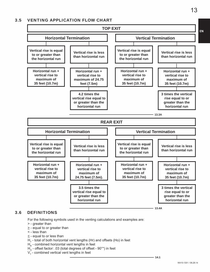

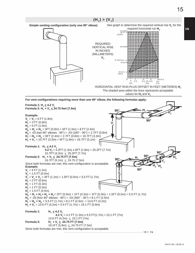


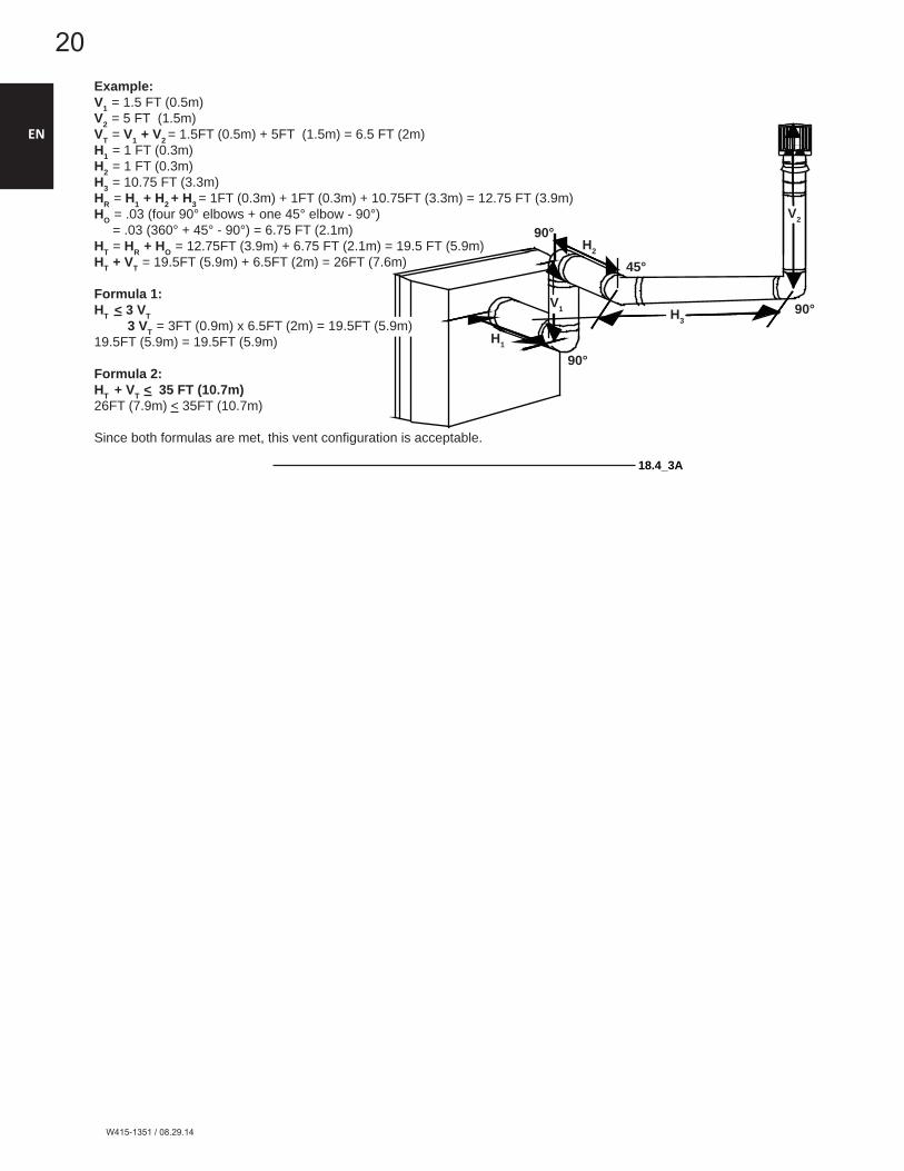


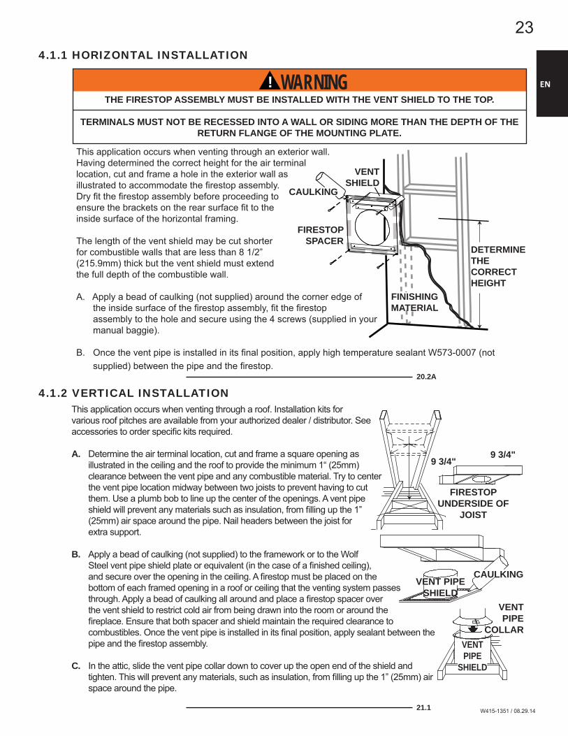


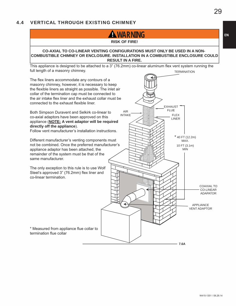


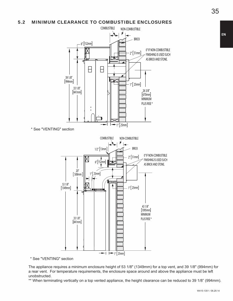


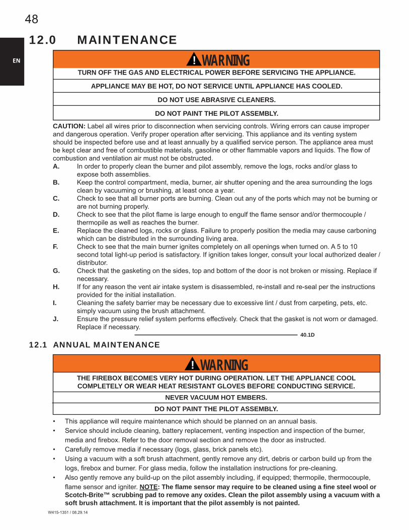
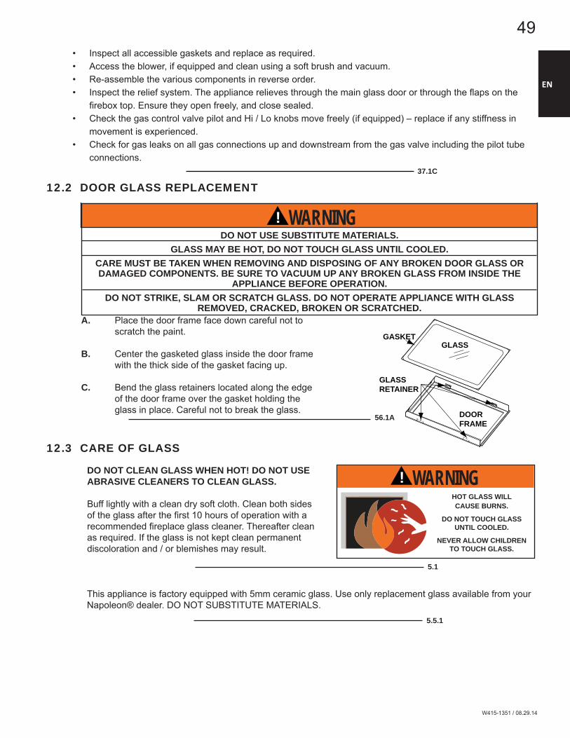


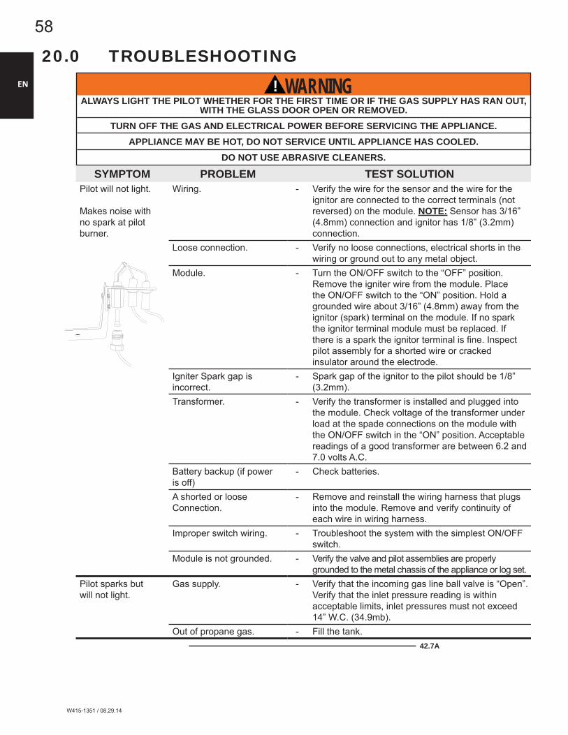


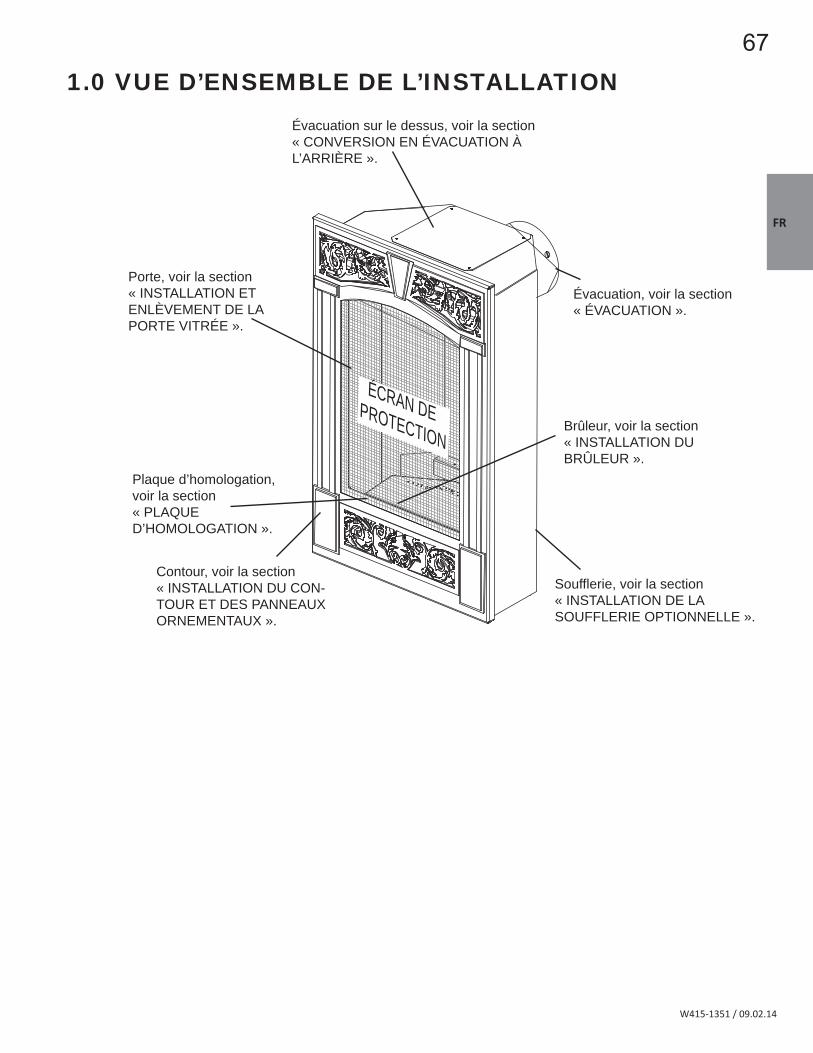


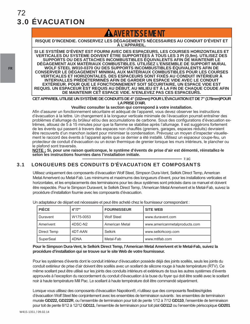

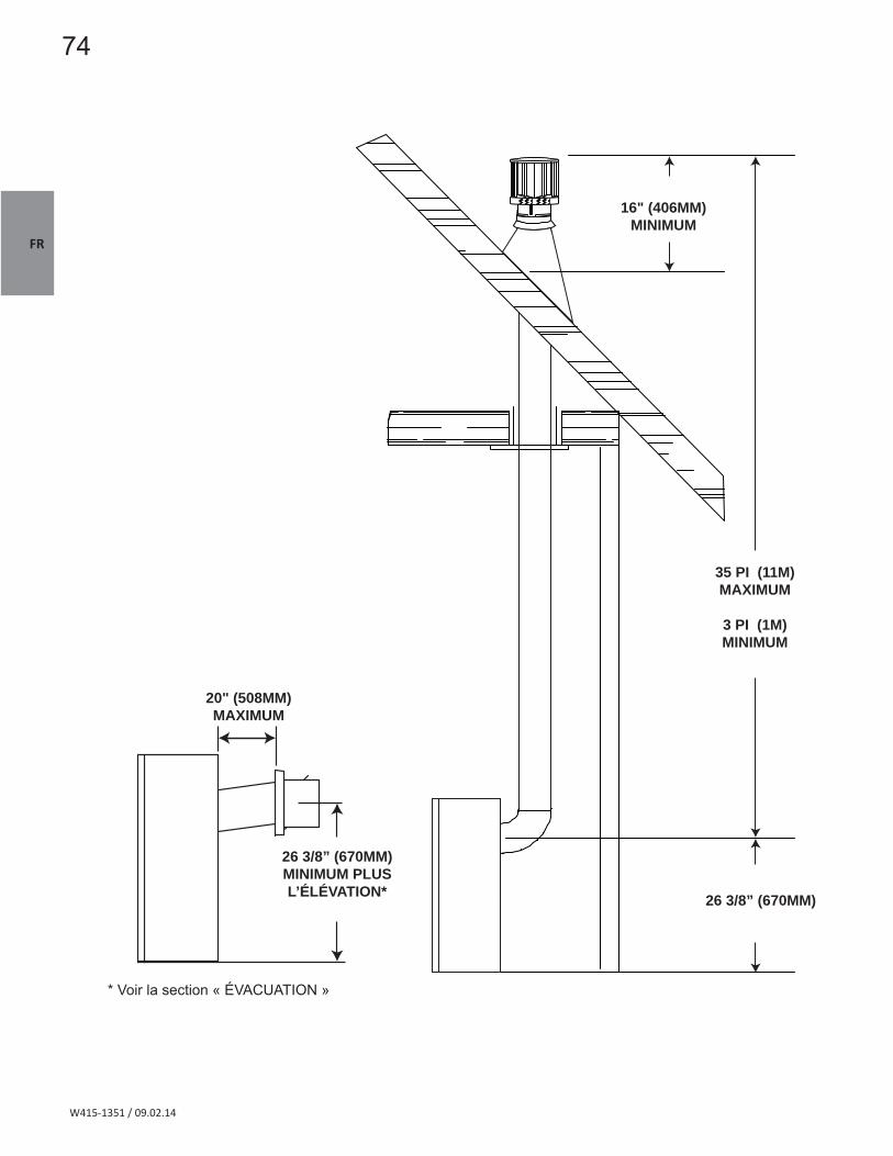


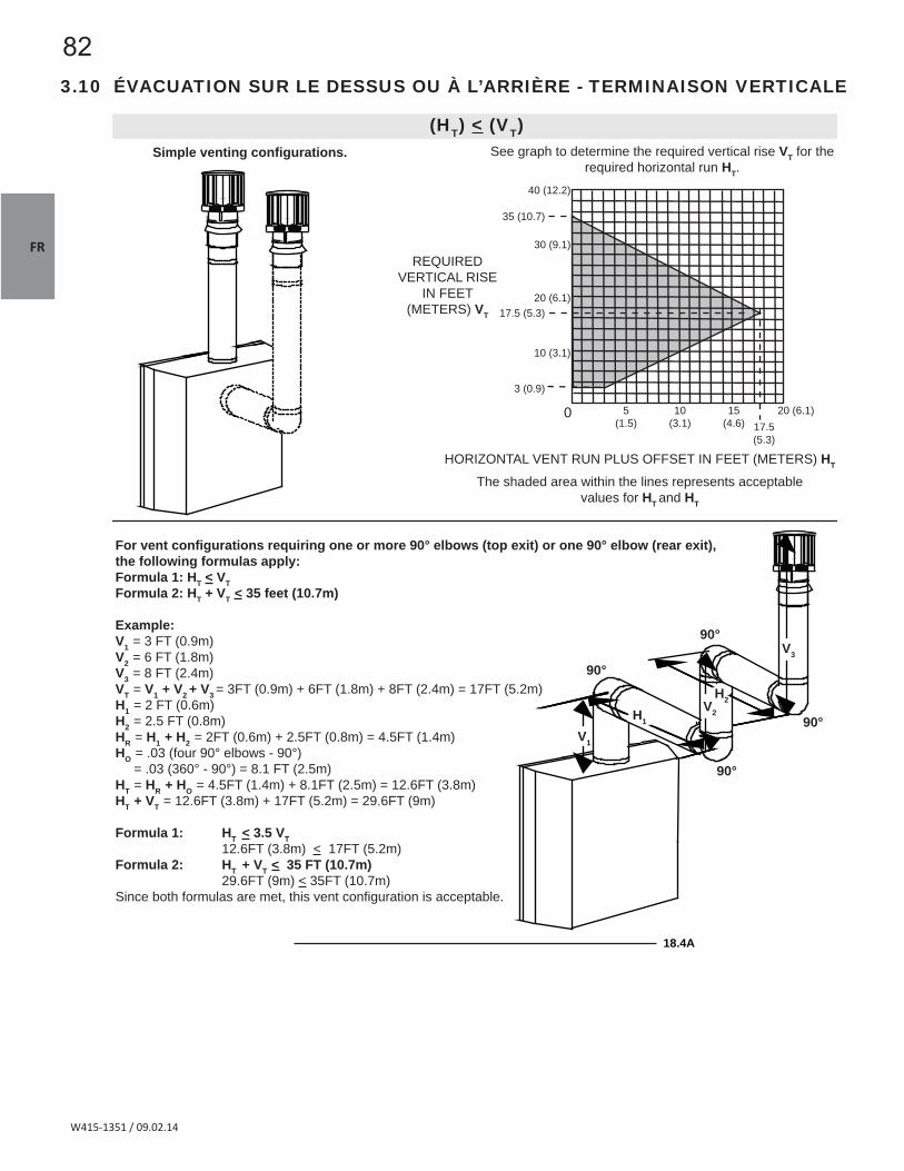

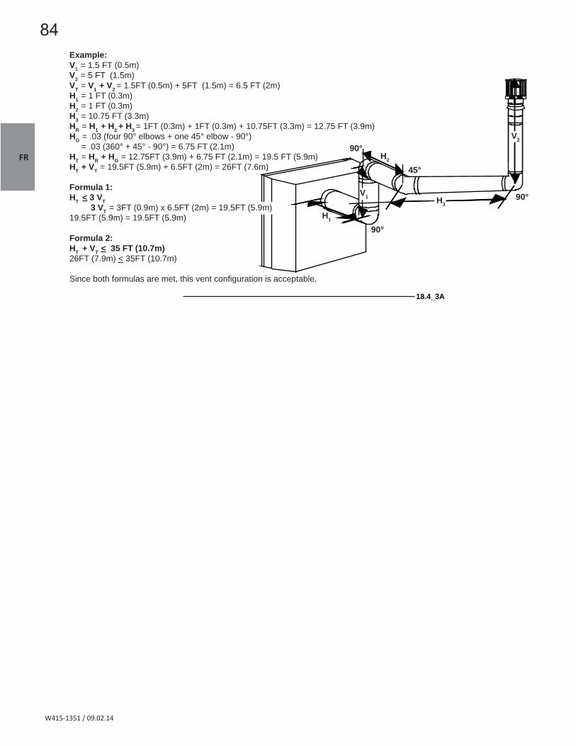


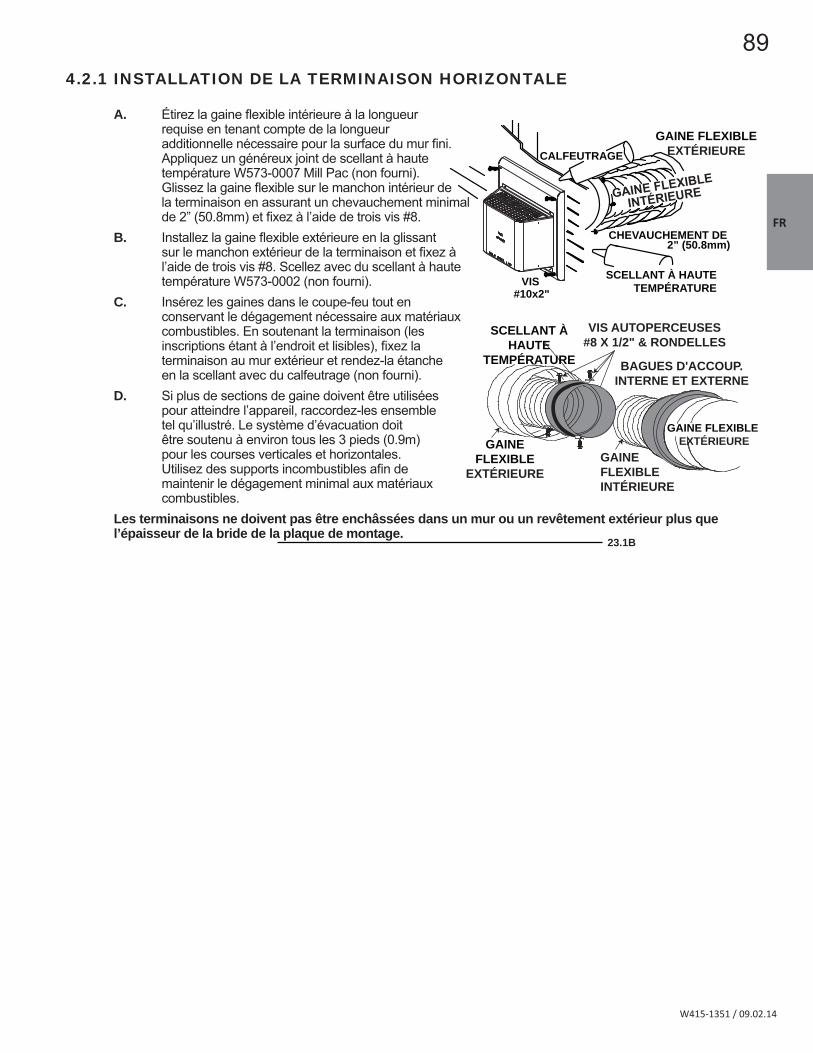
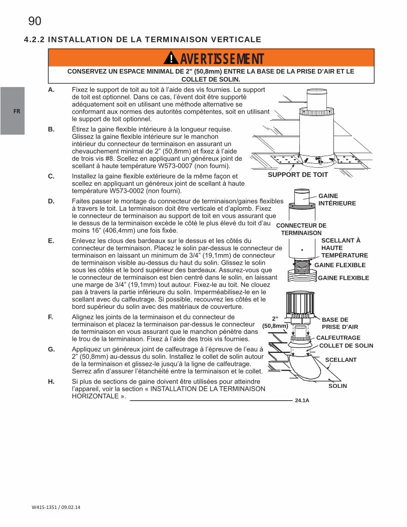


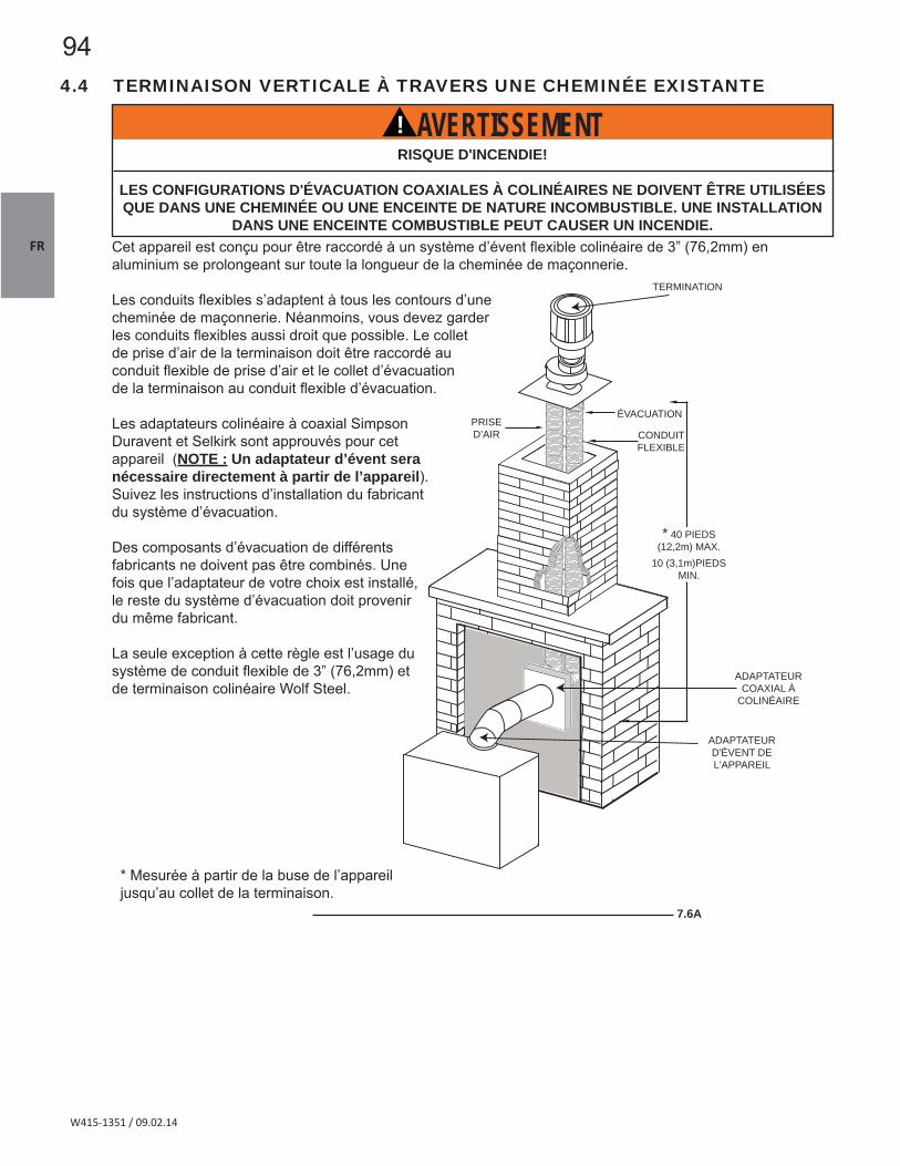


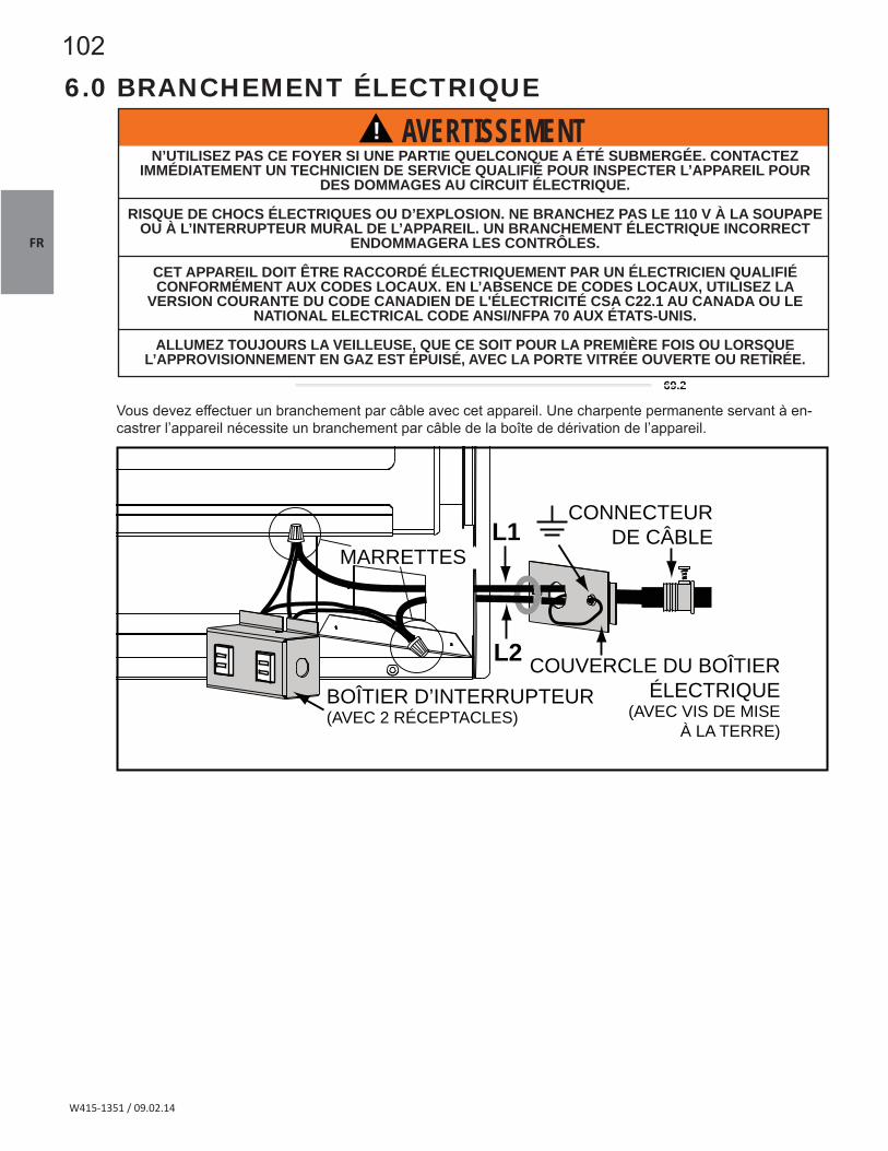
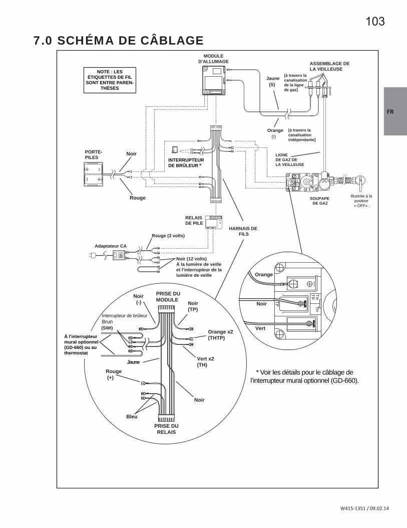


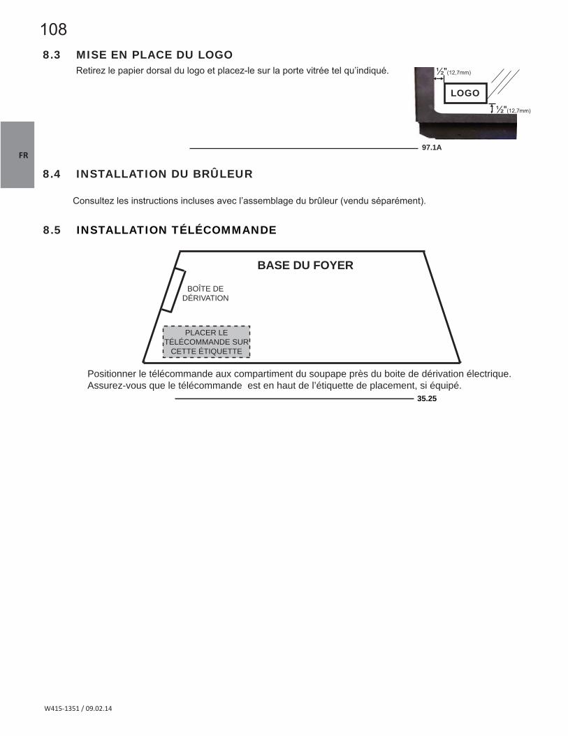


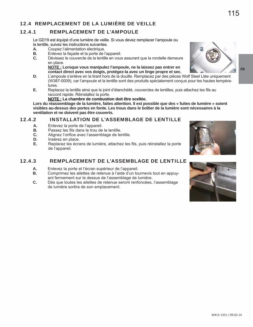
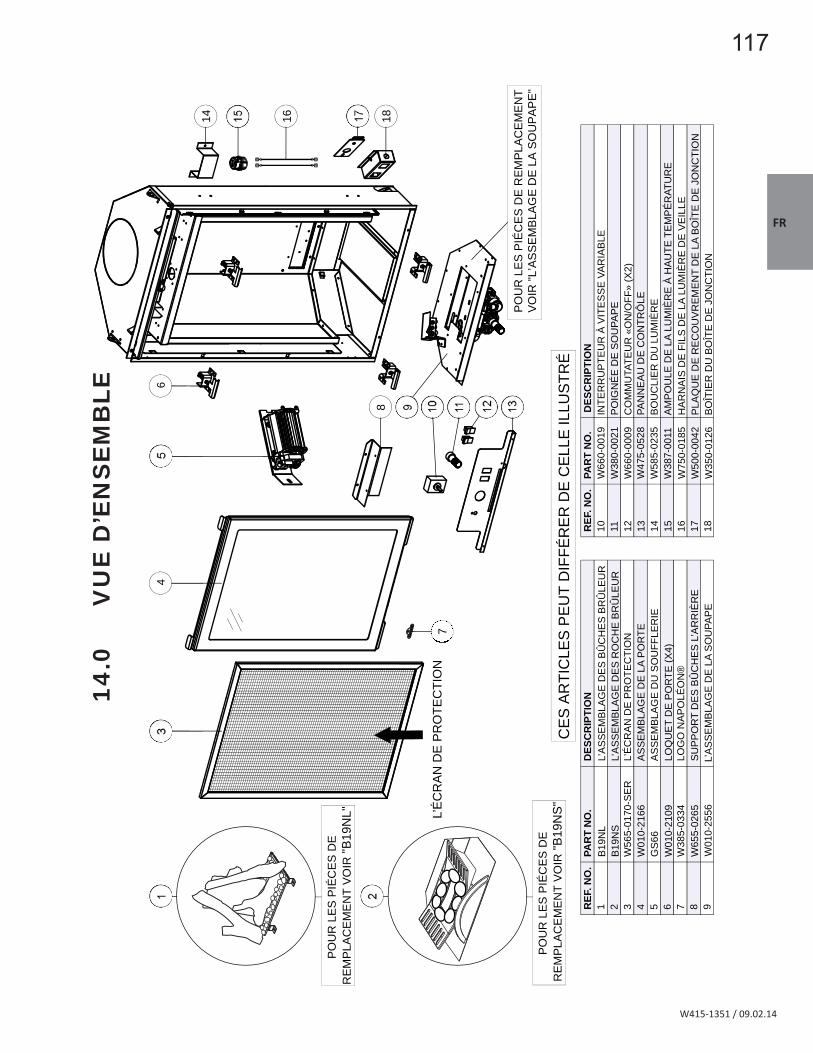


![8.6 - Airbag [OCR]](https://static.documents.pub/doc/80x56/577cc3b21a28aba71196e312/86-airbag-ocr.jpg)


