ST AND ARD AIR LIFT INSTRUCTIONS PARTS DRAWING PARTS LIST WARNING: READ INSTRUCTIONS BEFORE OPERATING 1. Center load on table - 1000 lb. maximum. 2. Connect to 100 psi maximum shop air. 3. Keep safety bar in position at all times - except when lowering. 4. Keep hands and tools from under carriage. 5. Do not mount table when in elevated position. 6. Do not ride vehicle onto lift. 7. Lift must be in the lowered position when moving. 8. Only trained persons should operate Air Lift. 9.The working area should be sufficiently lit. 10. Foot controller should be at least 3 feet away from Air Lift during raising and lowering operation. 11. Recommended for indoor use only. HANDY DIVISION OF JADEIM, LLC 401 South 2nd. Marshalltown, IA 50158 Ph: 855-752-5446 Fax 641-752-1205 www.handyindustries.com PN# 10740 -16749 -16600 - 10741
Transcript
STANDARD AIR LIFTINSTRUCTIONS l PARTS DRAWING l PARTS LIST
WARNING: READ INSTRUCTIONS BEFORE OPERATING
1. Center load on table - 1000 lb. maximum.
2. Connect to 100 psi maximum shop air.3. Keep safety bar in position at all times - except
when lowering.4. Keep hands and tools from under carriage.5. Do not mount table when in elevated position.6. Do not ride vehicle onto lift.7. Lift must be in the lowered position when moving.8. Only trained persons should operate Air Lift.9.The working area should be sufficiently lit.
10. Foot controller should be at least 3 feet away fromAir Lift during raising and lowering operation.
11. Recommended for indoor use only.
HANDY DIVISION OF JADEIM, LLC401 South 2nd. Marshalltown, IA 50158 Ph: 855-752-5446 Fax 641-752-1205 www.handyindustries.com
PN# 10740 -16749 -16600 - 10741
NOTE: READ ENTIRE MANUAL TO COMPLY WITH ALL SAFETY AND SERVICE PRECAUTIONS. DEATH, PERSONALINJURY AND/OR PROPERTY DAMAGE MAY OCCUR UNLESS INSTRUCTIONS ARE FOLLOWED CAREFULLY.
INSTRUCTIONS
UNPACKING AND SET-UP
1. Open carton, then remove ramp, and shipping boards.
2. CAREFULLY TURN TABLE UPRIGHT INTO OPERATING POSTION BEFORE REMOVING SHIPPING
CABLE RESTRAINT FROM SCISSOR MECHANISM.
3. Connect foot-operated air valve to 100 psi air supply. The lift may be damaged and/or
personal injury may result if the pressure exceeds the maximum 100 psi rating.
4. Stand clear of lift table and depress the UP side of foot valve to raise table.
5.To lower table, lift detent bar from safety latch and lower to next position or to floor.
6. Insert ramp mounting pins into holes at either end of table to mount ramp.
NOTE: If cycle vise is being installed, ramp must be mounted opposite the cycle vise.
OPERATION
1. Loads must be centered on table at all times.
2. Loads must be firmly positioned and secured on table at all times.
3. All moving parts have been lubricated at the factory and should be re-lubricated every 6
months to prevent galling. Grease zerks are located at each end of frame pivot shaft and at
top ends of inside frame assembly.
4. Lightly oil cylinder rod when it becomes dry.
5. Squirt some oil through air bleed hole in plate end of cylinder to lubricate piston and its
seal every 6 months.
6. Pivot shaft set screws should be checked frequently to be sure they are tight.These are
located at the top end of the inside frame assembly.
OTHER OPTIONS AVAILABLE
Separate installation instructions included with each option.
PART # DESCRIPTION
14476 CV-17 CYCLE VISE – Vise with removable wheel stop built into vise
10728 12” SIDE EXTENSIONS (2) – Expands width of lift from 24” to 48” includes stabilizer bar
16011 13” FRONT EXTENSION – Extends lift top to 93” for longer wheel base motorcycles
10736 13” REAR EXTENSION – Extends lift top to 93” for longer wheel base motorcycles
15566 RAMP END EXTENSIONS – Attaches to end of lift ramp for a more gradual incline to prevent bigger bikes from dragging bottom.
10737 SNOWMOBILE WING KIT – Used when lifting snowmobiles
16355 CE FOOT PEDAL – Covered foot pedal
10732 LIFT DOLLY – Helps move lift while in down position
Handy Industries Division of Jadeim LLC, warrants to the original purchaser of this product, all parts to be free from defects
in manufacture for a period of one (1) year from date of delivery. Notice of a defective part must be received in writing at
Handy Industries within one (1) year of purchase. All defective parts must be returned to Handy Industries and which,
upon our examination any parts which are defective in manufacture or workmanship, will be replaced or put in good oper-
ating condition. This warranty does not apply to damage resulting from accident, improper installation, repair, operation
or maintenance, negligence or neglect. THE COST OF SUCH REPLACEMENT OR REPAIR SHALL BE EXCLUSIVE REMEDY FOR
ANY BREACH OF ANY WARRANTY AND HANDY INDUSTRIES SHALL NOT BE LIABLE TO ANY PERSON FOR CONSEQUENTIAL DAM-
AGE, OR INJURY, OR COMMERCIAL LOSS RESULTING FROM ANY BREACH OF WARRANTY. HANDY INDUSTRIES MAKES NO
WARRANTY OR MERCHANTABILITY, MAKES NO WARRANTY OF FITNESS FOR A PARTICULAR PURPOSE AND MAKES NO OTHER
WARRANTY EXPRESSED OR IMPLIED, INCLUDING IMPLIED WARRANTY ARISING FROM THE COURSE OR DEALING OR USAGE
OF THE TRADE.
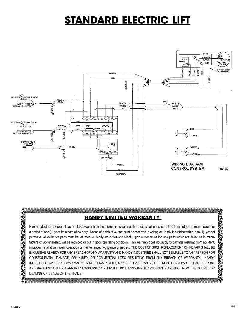
STANDARD ELECTRIC LIFTWITH PUSHBUTTON CONTROL
1.This is for the operation on a 115 volt, 60 Hz. circuit only.2. Do not remove ground prong from plug.3. Center load on table - 1000 lb. maximum.4. Keep hands and tools from under carriage.5. Do not mount table when in elevated position.6. Do not ride vehicle onto lift.7. Lift must be in the lowered position when moving.8. Only trained persons should operate Electric Lift.9.The working area should be sufficiently lit.
10. Recommended for indoor use only.
WARNING: READ INSTRUCTIONS BEFORE OPERATING
P/N 10742
HANDY DIVISION OF JADEIM, LLC401 South 2nd. Marshalltown, IA 50158 Ph: 855-752-5446 Fax 641-752-1205 www.handyindustries.com
l INSTRUCTIONS l PARTS DRAWING l PARTS LIST
STANDARD ELECTRIC LIFT
NOTE: THIS SYMBOL MEANS WARING OR CAUSTION: DEATH, PERSONAL INJURYAND/OR PROPERTY DAMAGE MAY OCCUR UNLESS INSTRUCTIONS ARE FOLLOWEDCAREFULLY. READ ENTIRE
POWER SUPPLY
This lift is for operation on 115 volt, 60 Hz current only. Check outlet voltage before plugging in equipment.WARNING: This lift is equipped with a 3-prong plug which must be plugged into a grounded 115 volt, 60 Hz power supply for your safety. Removing ground prong from plug or failure to plug into a grounded receptacle may result in a fatal electric shock.
UNPACKING AND SET-UP
1. Open carton, then remove ramp and shipping boards.2. Keeping hands free of lift mechanisms to avoid personal injury-CAREFULLY turn left over.3. Insert ramp mounting pins into holes at either end of table to mount ramp. NOTE: If cycle vise
is being installed, ramp must be mounted opposite the cycle vise.
OPERATION-LUBRICATION
1. Loads must be centered on table at all times.2. Loads must be firmly positioned on table at all times.3. All moving parts have been lubricated at the factory and should be re-lubricated occasionally to pre
vent galling. Grease zerks are located at each end of frame pivot shaft and at top ends of inside frame assembly.
4.The drive screw, motor and gear box were factory lubricated, and this lubrication should last for the life of the lift. Should re-lubrication be necessary, use a No. 9 multi-purpose gear oil in gear box and an “O”grade gear grease on drive screw.
5. Frame/motor pivot shaft set screws should be checked frequently to be sure they are tight.These are located at the top of the inside frame.
INSTALLING
The drive train components have been burnished in to give a tight, well working fit and will be stiff for thefirst few cycles. If drive screw should seize, put a few drops of oil on screw and reverse a few times. If
motor should pull down or hum,TURN OFF IMMEDIATELY. Check to see if drive screw is free.
Other Options
Available
Separate installationinstructions included
with each option
PART # DESCRIPTION
14476 CV-17 CYCLE VISE – Vise with removable wheel stop built into vise
10728 12” SIDE EXTENSIONS (2) – Expands width of lift from 24” to 48” includes stabilizer bar
16011 13” FRONT EXTENSION – Extends lift top to 93” for longer wheel base motorcycles
10736 13” REAR EXTENSION – Extends lift top to 93” for longer wheel base motorcycles
15566 RAMP END EXTENSIONS – Attaches to end of lift ramp for a more gradual incline to prevent bigger bikes from dragging bottom.
10737 SNOWMOBILE WING KIT – Used when lifting snowmobiles
10732 LIFT DOLLY – Helps move lift while in down position
16010 TOOL TRAY – Keeps tools organized and Handy
STANDARD ELECTRIC LIFT
ITEM PART NO DESCRIPTION QTY ITEM PART NO DESCRIPTION QTY
1 15685 ASSY TOP SAM 1 16 11315 BEARING CAM ROLLER 5304-2RS 4
2 11123 ASSY RAMP WELDED 1 17 11316 SPACER CAM BRG 13/16 X 1/8 X 1-1/2 FW 1