103

2

Warning!Hazardous Voltage: Can Cause Serious Injury or Death.
Disconnectpoweratmainpanelbeforeconnectingelectricalpowersupplyto PurWaterunitpanelorworkingonelectricalconnections.
WirePurWaterunitforcorrectvoltage.See“Installation&Operating Instructions”labelontheelectricalpanelcover.
MeetNationalElectricalCodeandlocalcodesforwiring.
FollowwiringinstructionsinthismanualwhenconnectingthePurWaterunit tothepowersource.
Caution! This Reclaim Unit has been evaluated for usewith water only.
ForAssistance,ContactPurWater800-882-8854
1

2
3
Reclaim Water Systems 5
Pre-Installation 7
Part 1
System Installation 11
System Installation - Extras 16
Wiring 21
Part 2
Quickstart Guide 23
System Start-up 25
Part 3
System Operation 31
Off Submenu 32
Auto Submenu 33
Operating the Reclaim Unit 41
Part 4
Maintenance Schedule 45
Part 5
System Troubleshooting 53
Troubleshooting Without a Fault on the HMI 70
VFD Faults 72
Part 6
Appendix 75
Warranty & RGA Information 99
Table of Contents

4
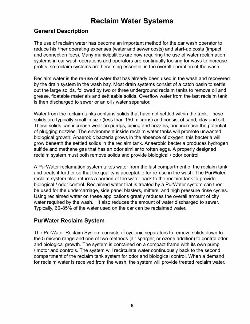
General Description
The use of reclaim water has become an important method for the car wash operator to reduce his / her operating expenses (water and sewer costs) and start-up costs (impact and connection fees). Many municipalities are now requiring the use of water reclamation systems in car wash operations and operators are continually looking for ways to increase profits, so reclaim systems are becoming essential in the overall operation of the wash.
Reclaim water is the re-use of water that has already been used in the wash and recovered by the drain system in the wash bay. Most drain systems consist of a catch basin to settle out the large solids, followed by two or three underground reclaim tanks to remove oil and grease, floatable materials and settleable solids. Overflow water from the last reclaim tank is then discharged to sewer or an oil / water separator.
Water from the reclaim tanks contains solids that have not settled within the tank. These solids are typically small in size (less than 150 microns) and consist of sand, clay and silt. These solids can increase wear on pumps, piping and nozzles, and increase the potential of plugging nozzles. The environment inside reclaim water tanks will promote unwanted biological growth. Anaerobic bacteria grows in the absence of oxygen, this bacteria will grow beneath the settled solids in the reclaim tank. Anaerobic bacteria produces hydrogen sulfide and methane gas that has an odor similar to rotten eggs. A properly designed reclaim system must both remove solids and provide biological / odor control.
A PurWater reclamation system takes water from the last compartment of the reclaim tank and treats it further so that the quality is acceptable for re-use in the wash. The PurWater reclaim system also returns a portion of the water back to the reclaim tank to provide biological / odor control. Reclaimed water that is treated by a PurWater system can then be used for the undercarriage, side panel blasters, mitters, and high pressure rinse cycles. Using reclaimed water on these applications greatly reduces the overall amount of city water required by the wash. It also reduces the amount of water discharged to sewer. Typically, 60-85% of the water used on the car can be reclaimed water.
PurWater Reclaim System
The PurWater Reclaim System consists of cyclonic separators to remove solids down to the 5 micron range and one of two methods (air sparger, or ozone addition) to control odor and biological growth. The system is contained on a compact frame with its own pump / motor and controls. The system will recirculate water continuously back to the second compartment of the reclaim tank system for odor and biological control. When a demand for reclaim water is received from the wash, the system will provide treated reclaim water.
Reclaim Water Systems
5

PW 050/100/200/300/350/400-M5 Series Systems
The PW 050/100/200/300/350/400-5M series systems consist of high efficiency cyclonic separators, a pump / motor, controls and one of two odor control systems, either an air sparger, or ozone addition. The standard systems are designed to treat 30, 60, 90 and 120 Gallons Per Minute (GPM) of reclaim water. The new generation of high efficiency cyclones will remove down to 5 micron solids, so that the treated water can be used by high pressure touchless or friction in-bay automatics as well as tunnel wash applications. The system utilizes a Variable Frequency Drive (VFD) on the pump motor which is controlled by the wash demand, to vary the amount of water that is treated and delivered. Water is recirculated back to the reclaim tanks. This is a continuous process both when water is demanded by the wash and when there is no demand. Up to three different activation inputs from the wash can be incorporated into the control box. The PW050/ 100/200/300/350/400-5M system piping also incorporates a city water intake line for use as: 1) a bypass solenoid to meet wash water demands in case the system is not operating due to a system fault; and 2) an automatic pump prime operation for system start-up.
Air Sparger
Biological and odor control are accomplished by using one of two methods, depending upon the model number supplied. The first method uses an air sparger (models ending in 5MAS), which is mounted within the reclaim tank above the water level. The air sparger will bring in air as water is passed through the sparger. The aerated water will add oxygen to the tank water which will control the anaerobic bacteria growth.
Ozone
The other method utilizes ozone to kill the bacteria (models ending in 5M06O, 5M12O or 5M24O). Ozone is a contact killing agent, similar to chlorine used in city water. Ozone (O3) is generated by concentrating the oxygen (O2) in ambient air and passing the concentrated oxygen through a high voltage electric current to produce ozone. The ozone laden gas is then inducted into the recirculation water stream and into the reclaim tank to kill the bacteria.
Caution: Inhaling concentrated ozone can create severe breathing problems. Precautions must be made to prevent exposure to
concentrated ozone.
6
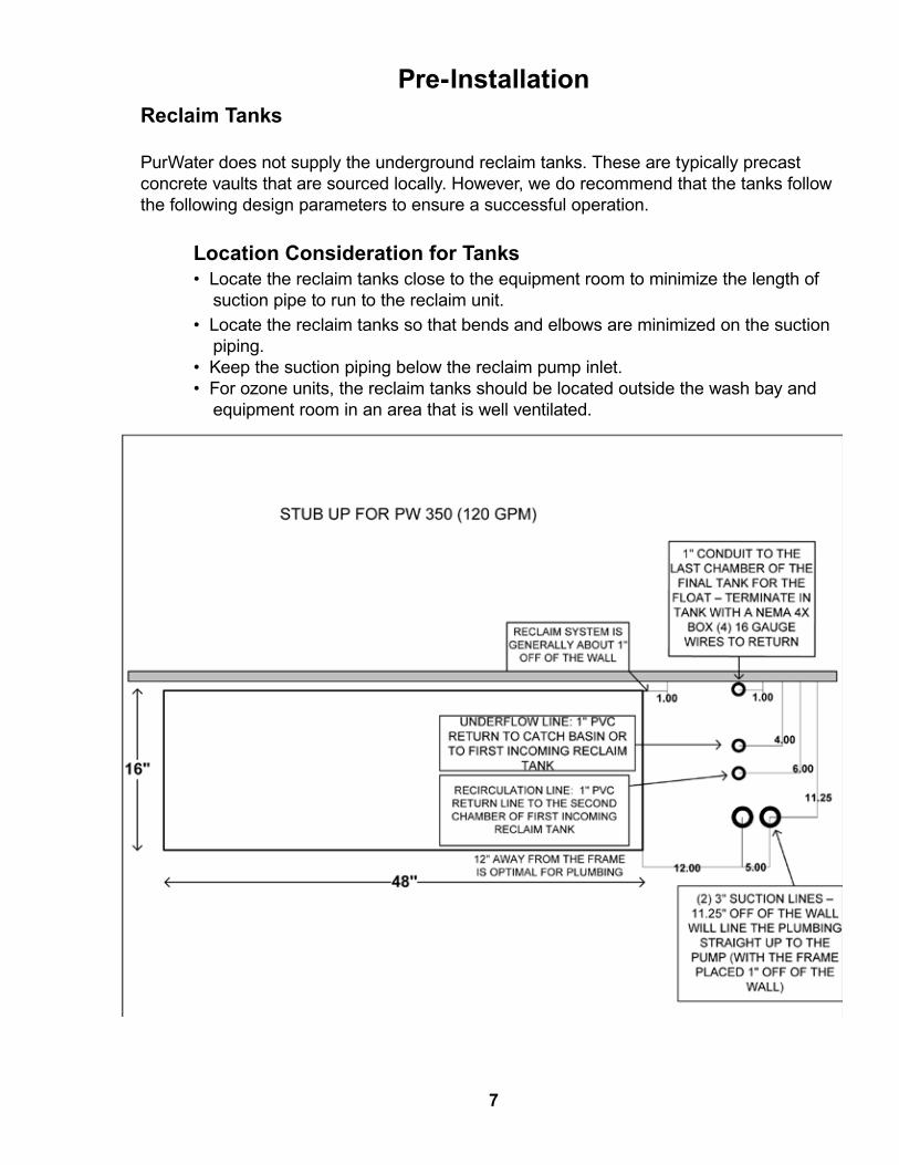
Reclaim Tanks
PurWater does not supply the underground reclaim tanks. These are typically precast concrete vaults that are sourced locally. However, we do recommend that the tanks follow the following design parameters to ensure a successful operation.
Location Consideration for Tanks • Locate the reclaim tanks close to the equipment room to minimize the length of suction pipe to run to the reclaim unit. • Locate the reclaim tanks so that bends and elbows are minimized on the suction piping. • Keep the suction piping below the reclaim pump inlet. • For ozone units, the reclaim tanks should be located outside the wash bay and equipment room in an area that is well ventilated.
Pre-Installation
7
Interconnecting Piping • The piping between the tanks/compartments will set the liquid level in each tank. The elevation and downward elbow help prevent floating material and settled solids from moving to the next tank. • For the PW050/100 / 200 / 300 series, the interconnecting piping needs to be a minimum of 4”. For larger units, the minimum is 6”. Sewer Overflow • The sewer overflow connection is above the normal liquid level and will normally overflow while washing vehicles. • The sewer connection should slope downward to the main sewer line. • There must be a backflow preventer installed between the reclaim tanks and the main sewer line to prevent sewage from entering the reclaim tanks.
Low Level Switch • PurWater will supply one two-wire (yellow float) level switch, (Float is not required in standard underground setups.) • The float should be wired into a water-tight junction box within the reclaim tank and wired through the 1” conduit to the PurWater unit. • The float should be installed a minimum of 9” above the bottom of the check valve when the float is in the down position.
Misc. Items - Reclaim Tank Plumbing • Piping and conduit materials should be PVC. PurWater recommends using schedule 80 pipe as it is more durable than schedule 40. • All piping to/from the PurWater Unit should be accessible from a manway for frequent maintenance and troubleshooting. • All floor drains emptying into the reclaim tanks should be piped to go below the water level within the tanks. This prevents any gas from backing up through the line into the bay or the equipment room. This is especially important for ozone units. • The following should not be piped into the reclaim system: Domestic sewer lines (sinks/toilets); backwash from carbon tanks; regeneration from softeners; blowdown from compressors or boilers; drains from service/ detail bays / areas where tire shine is applied. • If self serve bays are to be piped into the reclaim tanks, a separate reclaim tank should be used. Contact PurWater for details.
8

A
B
FRO
M
CA
R W
ASH
TO REC
LAIM
SYST
EM
END
OF
SPA
RGER
SHO
ULD
BE A
T LE
AST
6"
BUT
NO
MO
RE T
HAN
12"
FRO
M S
URFA
CE
OF
WA
TER
LEV
EL IN
TA
NK
DETA
IL A
SC
ALE
1 :
15
(2) 2
" OR
3" S
UCTIO
N
LIN
ES W
ITH F
ULL
FLA
PPER
C
HEC
K V
ALV
ES.
BOTT
OM
OF
VA
LVE
16" A
BOV
E FL
OO
RO
F TA
NK
DETA
IL B
SC
ALE
1 :
25
3 Ta
nk C
onfig
urat
ion
for A
ir Sp
arge
r Equ
ippe
d R
ecla
im S
yste
ms
9

A
B
TO
RECLA
IMSYSTEM
FROM
CA
RW
ASH
DETAIL A
SC
ALE 1 : 25
1" OZO
NE
RECIRC
ULATIO
N LIN
E.LO
CA
TE AT 24"
OR HA
LF OF W
ATER
LEVEL
DETAIL B
SCA
LE 1 : 25
(2)- 2" OR 3" SUC
TION
LINES W
ITH FULL FLAPPER
CHEC
K VA
LVE.
LOC
ATE BO
TTOM
OF
VA
LVE 16" FRO
M TA
NK
FLOO
R. 3 Tank Configuration for O
zone Equipped Reclaim
System
10

PurWater systems are designed for easy installation. However, if you should have any questions please contact us at (916) 978.9990 or (800) 882.8854 in Sacramento, CA. Our office hours are 7am to 5pm PST, Monday through Friday.
For All PW050/100/200/300/350/400-5M Series Reclaim Systems
Frame
The system is to be installed in a clean, dry, temperature controlled and covered area. It is not designed to be in the wash bay or outdoors. The frame requires a floor space of 48” wide by 16” deep with a height of 75” (86” for ozone units). PW400 systems require a floor space of 60” wide by 24” deep with a height of 76” (88” with ozone).The system also requires a minimum clearance of 18” along the sides, front and top of all frames to allow for routine maintenance and inspection. The floor frame should be placed with its back along a wall and should be secured to the wall to prevent movement of the frame. The area should be free of excessive moisture which can cause extreme corrosion or electrical failure.
Piping
Fittings on these systems have some threaded connections which can come loose during shipment. There are two unions used on the motorized ball valve on the inlet piping, on the cyclone overflow piping, on the recirculation line, and on the Mazzei eductor (for ozone units) on the recirculation line. There are also two unions on the underflow flush (U/F flush) motorized ball valve. Re-tighten all union connections and any other threaded connections prior to introducing water into the system. PurWater recommends using Schedule 80 PVC for all connections to the reclaim unit.
System Installation
11

1. Treated Water LineThis line is to be connected to the wash where the unit is being used. Solenoid valves need to be installed and controlled by the wash controller when water is demanded by the wash. Do not reduce the line size until reaching the wash equipment to prevent flow restriction and pressure reduction. (See page 17 on direct feed for high pressure pumps.)
2. City Water LineCity water is to be connected, which will then provide fresh water for a bypass function to the wash and the pump prime sequence. The city water supply line needs to be 1” for the PW100 series and 2” for larger units to ensure enough presure and flow are available. City water should not exceed a pressure of 100 psi.
Cyclonic Separators
Pump/Motorand Basket
Strainer
1. Treated WaterLine
2. City Water Line
3. Recirculation Line
4. Pump Suction Line
5. Underflow Line
Ozone Generator
Oxygen Concentrator
12

3. Recirculation LineThis 1” line provides a return line of treated water back into the second compartment of the first reclaim tank. A solenoid valve (normally open) on this line closes only during the pump prime sequence.
Air Sparger Units (Models ending in -5MAS) See photo below
The recirculation line is connected to the air sparger within the reclaim tank. (See below for air sparger assembly installation.) Air Sparger Assembly The air sparger assembly is installed into the first reclaim tank (see drawing page 9). It should be located so that it is accessible from the manway as frequent inspection and maintenance are required. Ensure the wall mount bracket is placed to allow the assembly to be removed easily. The assembly consists of the air sparger, mounting brackets and inlet piping with a union. The bottom of the sparger nozzle should be set 6-12” above the water level and pointed downward. If this is not possible, mount the sparger horizontally so that it sprays against a side wall. The top opening on the sparger body should have clearance to allow air flow into the sparger. The union on the inlet allows the assembly to be easily pulled out of the tank for maintenance and inspection.
Air Sparger Assembly
Air Intake Opening (on top)
Air Sparger
Sparger Nozzle
Sparger Water Inlet
Wall Mount Bracket
PurWater System with Air Sparger
Sparger Water Outlet
13

Ozone Units (Models ending in -5M06O -5M12O or -5M24O) The recirculation line will be supplied with a Mazzei eductor connected to an ozone generation system. The line in the tank should extend and terminate in a tee to split the flow (see page 10). The tee should be placed 20-24” off tank floor or half of the water depth. An air sparger is not required with an ozone system. All piping containing ozone must be PVC.
PurWater System with Ozone
4. Pump Suction LineConnect the suction line from the last compartment of the last reclaim tank into the basket strainer inlet on the reclaim unit. Keep the size of the line 2” for the PW100 / 200 units and 3” for larger units. Piping between the tank and reclaim system should have a minimal amount of bends, threaded connections and should never go higher than the basket strainer inlet. The inlet pipe within the tank should have a flapper type foot valve at the very end of it and a quick disconnect or union for maintenance. Unions must be above the water level to allow removal of the suction line from the manway to access foot valves without draining the tank. Unions must be tight to prevent suction loss. PurWater supplies two PVC flapper check valves to attach to the suction lines. The bottom of the valve in the tank should be a minimum of 16” above the bottom of the tank floor. Do not use spring loaded check valves or valves with screens on the suction line. Pressure testing of both suction lines is recommended before connecting to the reclaim unit. Two suction lines are recommended. One is for use and one is a spare.
14

5. Underflow LineConnect the 1” line from the bottom of the cyclones to the catch basin or trench. An underflow flush (or U/F flush) motorized ball valve assembly is installed on this line between two unions. Once per day the system will flush the underflow for one minute by opening the valve. The underflow line should be level or sloping downward to prevent solids build-up in the piping or cyclones.
Underflow orifice assembly with 1” motorized ball valve
15

Some reclaim systems are ordered with extra features. This manual covers the most common ones. If installing something that does not pertain to these three, check the back of this manual for any site specific diagrams or instructions.
AquaLink (AOS)The 2.0 Reclaim is set up for simple and quick installation of the AOS system add-on. Plumb the system as follows: 1) Glue the male adaptor (supplied) to the recirculation line output as indicated in the picture. 2) Plumb from the male adaptor to the AOS inlet port (top fitting) 3) Plumb the AOS outlet port (bottom) to the recirculation line “stub up” on the equipment room floor. There is no wiring required, simply unscrew the black cover from the AOS receptacle and screw in the yellow cable from the AOS control box (see photos below). Please note: There is a finder pin in the receptacle and cable so there is only one way it will screw together. Verify the dip switch settings and that the pump runs when it should.
System Installation - Extras
AOS receptacle on reclaim control box closed (left) and open (right)
Yellow cable from AOS
Recirculation Line Output
Male Adaptor
Trench FlushPlumb the solenoid so it is teed on the product line and the output is going to where it is spraying down the trench. Wire the solenoid to the blue terminals as shown on the electrical diagram that corresponds with that control box (see wiring diagrams, page 73).
Chain RinsePlumb the solenoid so it is teed on the product line and the output is going to where it is spraying water on the conveyor chain. Wire the solenoid to the yellow terminals as shown on the electrical diagram that corresponds with that control box (see wiring diagrams, page 73).
16

PURW
ATE
R RE
CLA
IM S
YSTE
MFR
ESH
WA
TER
HEA
DER
FRES
H W
ATE
R FI
LLM
ECHA
NIC
AL
FLO
AT
CO
NTR
OLL
ED
REC
LAIM
SYS
TEM
PRO
DUC
T LI
NE
DIR
ECT
FEED
TO
PUM
P ST
AN
D
REC
LAIM
SYS
TEM
SUC
TION
LIN
E FR
OM
U/G
TA
NKS
REC
LAIM
SYS
TEM
UN
DER
FLO
WLI
NE
TO U
/G T
AN
KS O
R C
AR
WA
SH P
IT
OV
ERFL
OW
TO
SEW
ER
FRES
H W
ATE
RHO
LDIN
G T
AN
K
FRES
H W
ATE
RBY
PASS
OZO
NE
REC
IRC
ULA
TION
LIN
ETO
U/G
TA
NKSPU
RWA
TER
REC
LAIM
SYS
TEM
FRES
H W
ATE
R FI
LLM
ECHA
NIC
AL
FLO
AT
CO
NTR
OLL
ED
OV
ERFL
OW
TO
SEW
ER
FRES
H W
ATE
RHO
LDIN
G T
AN
K
FRES
H W
ATE
RBY
PASS
3315
Ora
nge
Gro
ve A
veN
orth
Hig
hlan
ds,
CA
956
60A
PPRO
VE
DA
TE:
REV
. BY:
DRA
WIN
G N
O.
APP
ROV
ED B
Y:D
ATE
:D
RAW
N B
Y:SC
ALE
: NO
NE
REV
ISIO
N D
ESC
RIPT
ION
REV
ISIO
N
N/A
2-22
-201
1JO
2-22
-201
1JO
Recl
aim
Dire
ct F
eed
to P
ump
Stan
dPW
-REC
LMD
F
CO
MM
ENTS
:
MA
TERI
AL
/ FI
NIS
H:
THE
INFO
RMA
TION
CO
NTA
INED
IN T
HIS
DRA
WIN
G IS
THE
SO
LE P
ROPE
RTY
OF
NEW
WA
VE
IND
USTR
IES.
AN
Y RE
PRO
DUC
TION
IN P
ART
OR
AS
A W
HOLE
WITH
OUT
THE
WRI
TTEN
PER
MIS
SIO
N O
FN
EW W
AVE
IND
USTR
IES
IS P
ROHI
BITE
D.
PRO
PRIE
TARY
AN
D C
ON
FIDE
NTIA
L
SHEE
T:1
OF
1
17

18

Warning!Hazardous Voltage: Can Cause Serious Injury or Death.
Please use caution when servicing the control box.
Disconnectpoweratmainpanelbeforeconnectingelectricalpowersourceto PurWaterunitpanelorworkingonelectricalconnections.
WirePurWaterunitforcorrectvoltage.See“Installation&Operating Instructions”labelontheelectricalpanelcover.
Thesupplyvoltagemustbewithin10%ofthedesignatedreclaimunitvoltage asshownonthe“Installation&OperatingInstructions”labelontheelectrical panelcover.IncorrectvoltagecancausefireorseriouslydamageReclaimunit andvoidwarranty.Consultalicensedelectricianbeforeapplyingpowertothe Reclaimsystem.
FollowwiringinstructionsinthismanualwhenconnectingthePurWaterunit tothepowersupply.
Caution! This Reclaim Unit has been evaluated for usewith water only.
ForAssistance,ContactPurWater800-882-8854
19

20

Wire the system according to the customer connections diagram below:
Please note: This diagram shows the standard reclaim wiring setup without any extra features. If the reclaim control box you are working on looks different, go to electrical schematics in the Appendix on page 73.
0 OFF
ABBK 10 AS 201
- 230 / 400
0 OFF0 OFF 0 OFF
ABBS 203K 30 A- 400
3
4
1
2
Bussmann t ON
CDNF32(N)7L
4
(N)8T4
33.9
AB
DC +L1 L2 L3 T1 T2 T3
DC- BR+ BR-
01 02 03 04 05 06 07 08 0911 12 13 14 15 16 17 18 19
R1R2R3
SIEMENS
LOGO!
OUTPUT 4 X RELAY/10A
Q1 Q2 Q4
I5 I6 I7 I8I1 I2 I4I3L1 N
Q3
ESC OK
LOGO!
Q1 Q2
Q4
I1 I2 I4I3L1 N
Q3
RUN/STOP
LOGO!
Q1 Q2
Q4
I1 I2 I4I3L1 N
Q3
RUN/STOP
SIEMENS
L1 N
+ - -
24VDC
110 V AC COMMPrime
O2/O3
Ground
A1
A2
14
11
12
100-125
A1
A2
14
11
12
100-125
A1
A2
14
11
12
100-125
A1
A2
14
11
12
100-125
A1
A2
14
11
12
100-125
A1
A2
14
11
12
100-125
1 2 63 4 5 6 7 8
Float
Act 1
Act 2
Act 3
Act 1 relay
Act 2 relay
Act 3 relay
3 Phase***
1 Phase**
Relays 1-6****
White wire
Float/ Activation terminals*
PURWATER STANDARD 5 MICRON RECLAIMCONTROL PANEL CUSTOMER CONNECTIONS
*Float not required to run system but is recommended if it can be installed where it can be accessed later should it need to be replaced. Float is normally closed. One activation is required, the other two are provided in case multiple washes or applications are being used. If ordered, trench flush terminals are always blue and chain rinse terminals are always yellow and not numbered but always are to the right of numbered terminals.**Single phase 110v shown is the standard in the United States. Outside of the US, voltage, wiring and wire color may vary.***3 phase 208v shown. In US 3 phase may be 480 with brown orange and yellow wires instead of black red blue. Outside of US may vary.****Relays are identified as 1 through 6 from left to right and are as follows: 1=2" motorized ball valve, 2=1" motorized ball valve, 3=Bypass (Runs bypass if de-energized) 4-6=activation relays. 1-3 are always 110v (in US) 4-6 are the voltage they were ordered for the wash and can be 110v or 24v (in US). Verify act relays are the correct voltage for the carwash by reading the number above the indicator light.
Wiring
21
Single phase (110V) must be wired to a 20 amp dedicated circuit breaker. Three phase must be wired to a 30 amp (208) or 15 amp (460) dedicated circuit breaker. PW400 systems require a 40 amp (208) or a 20 amp (460). Float is not required but if used, it should be installed where it can be replaced if necessary. Only one activation is required; however, three are supplied by PurWater in case they are needed.
Examples for Activation
A signal indicating the tunnel conveyor is on or a signal indicating there is a car in the automatic bay is sufficient and simple. If that is not an option, use the signal that opens the solenoid for each application you are using reclaim for (one for mitters, another for undercarriage, etc.). All activations send a signal to run the pump on the transducer, therefore there is no difference between acts 1, 2 or 3.
Please note: If your control box has more terminals than the 1-8 shown in the diagram, go to electrical schematics in the Appendix on page 73 to find the correct diagram. For more information on the relay bank and how each relay operates within the system, go to the Operation section on page 31.
22

1. Verify that the system is plumbed and wired according to drawings and schematics. 2. Set the clock on the HMI. Refer to the set clock guide.
3. In the Startup Menu press F4 to check pump rotation.
4. Go to Hand and run wash, 2nd line down should change to “Wash Act On” when the car wash comes on. This will also run the bypass solenoid. Please note: You must press and hold the Hand button until you see a change in the screen, this is true for all HMI function buttons.
5. Verify underground tanks are full, press Auto on the HMI.
6. If no faults show on screen, start prime sequence by following HMI prompt and immediately press Prime.
7. Loosen the lid on the basket strainer and wait for water to come out. 8. Once water comes out, tighten lid back down. After 30-45 seconds pump should turn on.
9. If pump does not come on within said time press Off and then Auto, let pump run and verify pump is holding steady roughly 15-20 psi. 10. If pump is not holding 15-20 psi, you may have to run the prime sequence a few more times to get the air out of the suction line.
11. If you try the prime mode multiple times and cannot catch prime contact PurWater.
12. Check for leaks and verifiy ozone or sparger is operating properly.
Please refer to the detailed instructions on the following pages for clarification on the above steps. If you need further assistance, please
contact PurWater at 800.882.8854.
Quickstart Guide
23

24
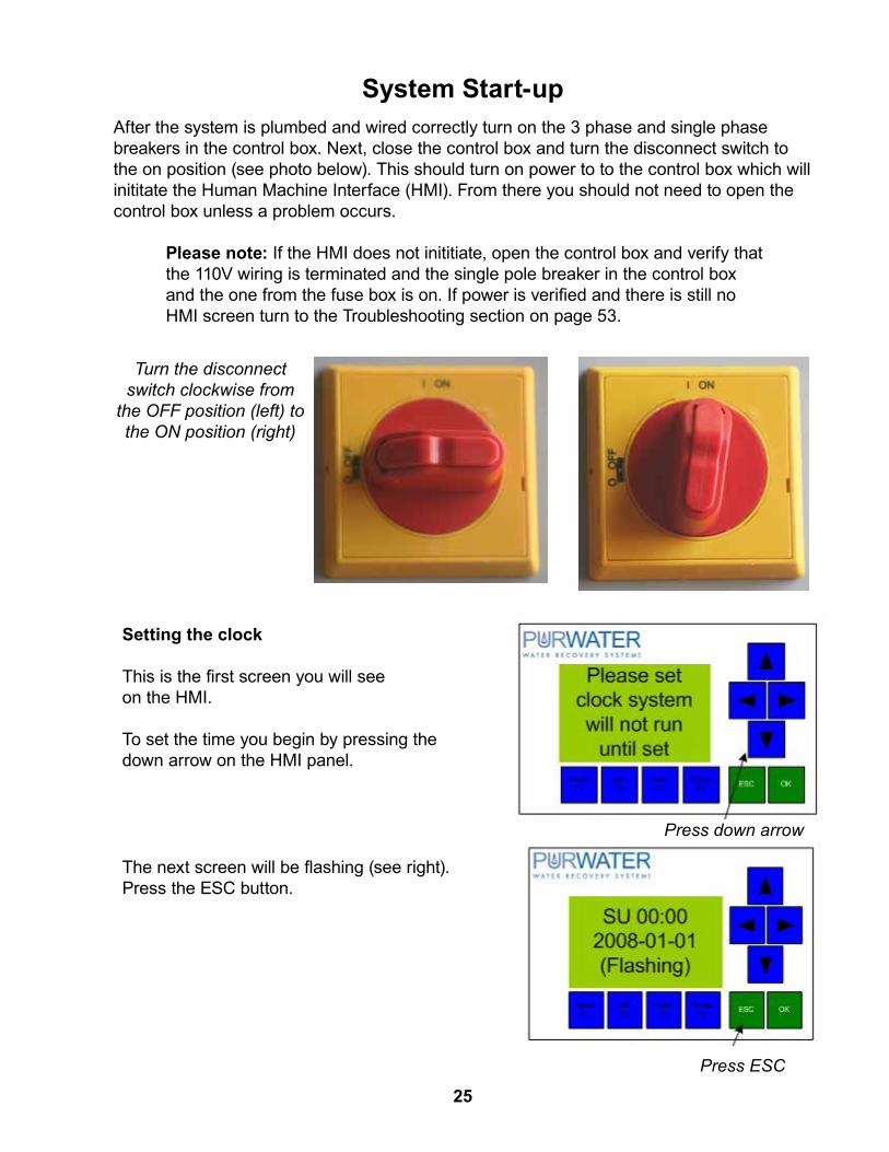
After the system is plumbed and wired correctly turn on the 3 phase and single phase breakers in the control box. Next, close the control box and turn the disconnect switch to the on position (see photo below). This should turn on power to to the control box which will inititate the Human Machine Interface (HMI). From there you should not need to open the control box unless a problem occurs.
Please note: If the HMI does not inititiate, open the control box and verify that the 110V wiring is terminated and the single pole breaker in the control box and the one from the fuse box is on. If power is verified and there is still no HMI screen turn to the Troubleshooting section on page 53.
Setting the clock
This is the first screen you will see on the HMI.
To set the time you begin by pressing the down arrow on the HMI panel.
Press down arrow
Press ESC
The next screen will be flashing (see right). Press the ESC button.
Turn the disconnect switch clockwise from
the OFF position (left) to the ON position (right)
System Start-up
25

Press arrow down until Set..
Next, scroll through the menu to the “Set” option by using the down arrow on the HMI panel. Press OK.
The next screen should look like this. Press OK two times.
Press OK X2
Use the up and down arrows to change and the left and right arrows to move to the next/last. Press OK when finished.Please note that the clock uses military time. (Ex: If the time is 1:00PM - the clock will read 13:00.)
Please make sure you set the correct time or it will affect the operation of the system. For further assistance, contact PurWater.
To exit out of the set time menu, press ESC three times then the up arrow to enter the next section.
Please note: Buttons are called out sometimes as F1, F2, F3 and F4. They are called out by their F numbers when they are not used for their primary functions. Example: Press F3 in Auto mode; the system is already in Auto, the button then serves as a different function, F3. However, Off and Hand still will serve as Off and Hand if the system is in Auto. It is not necessary to hold ESC or OK when pressing these buttons to make them F#. The prime button is called out as Prime only when it is used to prime the system, all other times it is F4. Press and hold Hand Off Auto and Prime buttons firmly until you see desired action or change in screen. When scrolling through menus, wait 5 seconds between pressing buttons, an easy way to be sure of the time is to wait until prompted to press a button by the HMI. If system is left in any screen other than the default for two minutes without a button being pressed, the program will revert it back to the default screen for that mode.
26

Once you have set the time, the HMI screen should look like this.The system is in Off. Press F2 for the Start Menu.
System offAuto=PumpHand=BypassF2=Startmenu
System off Hand=Bypass mode Auto=Reclaim F4=Rotate pump
Press and hold F4 to check the pump rotation. It will run the pump for 2 seconds so you may need to release and then press F4 again if you do not see the first time. The easiest way to check motor rotation is to put your finger on the motor shaft while it is turning (see photo). If the pump is not rotating in the correct direction, reverse the motor leads in the motor junction box and repeat to verify.
In Hand or Auto the reclaim will need a signal from the wash
After verifying the motor rotation make sure the wash activation is reaching the reclaim system. This can be done in Off, Hand or Auto. To do it in Hand, press Hand (bypass will come on with act). In Auto, do so after priming the system (see instructions below). If you need to keep the system in Off mode press F2 again.
Wash Act OffWash signal will change status to on……..
Then press F4.Run carwash, Wash Act Off will change to Wash Act On, if you have multiple activations be sure to verify them all.
Once motor rotation and wash activation are verified, and if reclaim tanks are filled with water, you are ready to prime the reclaim system.
Auto: Press prime now if you need to
prime system
First, make sure the city water is connected and the valve is open. Next press Auto, and the screen looks like this, immediately press prime.
Checking standard motor rotation PW400 motor on page 29
27

If the HMI screen reads anything other than Press Prime Now after pressing Auto, go to the Troubleshooting guide on page 53.
After you press Prime the screen should change to this.
Loosen the lid on the basket enough to where air can be released from the suction line, removal of the lid is unnecessary. When water starts squirting out of the basket strainer tighten the lid back down. Depending on the city water pressure, the pump should turn on automatically within a minute of tightening the lid back down. If it does not, press Off and then Auto to run the pump. Otherwise it will time out after 5 minutes (new to 2012). You may need to run the prime sequence multiple times to get all of the air out of the suction line. After priming is complete pump should be holding 15-20 psi.
Auto: System runs 24/7 if not faultedWash Act Off
After prime is achieved, run wash to check wash act if you have not already, also verify there is enough reclaim water to feed the carwash and double check for leaks. The screen should be showing this.
Activation will change to Wash Act On, if any other screen is displayed, refer to Troubleshooting guide on page 53.
If reclaim system has ozone, check that cell pressure is showing 8-8.5 psi (without closing the valve) and blue light is on (if the light is not on, visit the Troubleshooting section on page 53). If reclaim is a sparger unit, verify airflow through the sparger hole out in the first reclaim tank. There should be suction at port on top of sparger.
Air Sparger Assembly
Air Intake Opening (on top)
Blue light indicates
ozone output
28
Prime: Loosenbasket lidlet air outOnce water

System Start-up continued...
Leak Check After the pump has caught prime and is flowing water through the system, check for leaks in the piping and around the cyclones. A leak check should be done both when the system is running in recirculation only and when running with wash demand. Re-tighten any threaded connections on the piping and double check all unions. The cyclones are made in several pieces and the connection of these pieces can come loose during shipment. For leaks around the victaulic (orange metal clamps) connections of the metal band around the mid-section, re-tighten the connection (careful not to over-tighten). If the leak persists, the connection will need to be loosened and re-seated. For leaks around the bottom of the cyclone, the hose clamps can be re-tightened. There is also an inter-locking piece on the bottom cyclone piece which can be pushed up and turned to tighten. If further assistance is required, please contact PurWater.
Cyclonic Separators
Checking motor rotation on a PW400
29

30

OverviewThe PurWater Reclaim System 2.0 is designed to run in Auto. In Auto the pump runs continuously if no major faults are present. If a major fault is present the system turns the bypass on when the wash activation comes on. The pump runs on the Variable Frequency Drive (VFD) in one of two ways, either Recirculation or Wash. In Recirculation the pump runs at a preset speed, the recirc motorized ball valve (except on PW050 and PW100 units) is closed to run water through one cyclone only and the system constantly runs treated water back into the tank. During Wash Cycle, the pump speed varies as the VFD tries to maintain 40 psi on the treated water line, the recirc valve is opened to run water through all cyclones and the pump still recirculates some treated water back into the tanks. In both cycles the pump runs to the cyclonic separators to separate the solids from the water, keeping the treated water to use for the wash or to recirculate back to the first tank and isolating the solids to the catch basin or trench.
The major faults that will shut the pump down and open the bypass solenoid (with/on Wash Activation) are if the VFD is off, faulted or failed, the low level float (if installed) is down or if the pump runs under 7 psi for more than 10 seconds continuously. If a major fault clears on its own the system will go back to running the pump. Minor faults include if either of the ball valves will not open or close and require being acknowledged by pressing F4 (Prime). If the system has ozone installed, faults will shut only the ozone generator down and may clear on their own and the system will go back to running the ozone generator.
Hand and Off mode are available in the event you can not or do not want to run the reclaim system. For example, if you had a leak in the product line and it were being repaired, you would turn the system to Off. Or, when you are cleaning the basket strainer you would turn the system to Hand so you could run in bypass to keep the wash running.
System Operation
31

System off Hand=Bypass mode
Auto =Reclaim F2=More info
In Hand or Auto the reclaim will need a
signal from the wash…...
Recirc OpenShould show open If not look at port…...
F2
Wash Act OffWash signal will change status to
on……..
Startup/ Troubleshooting
Tutorial
F2
F4
Run wash/ Watch for status change
F2
F4Press & hold/ check
pump rotation
System off Auto=Pump
Hand=Bypass F2=Startmenu
F4Press & hold for 2 secs after cleaning
basket strainer
F2
In Hand the unit will open the bypass
when the wash act is on……..
If faults occur in Auto display flashes & fault
shows here on…...
F2
F2
Flush Closed Closed? If not look at
port If so……..
Press and hold buttons firmly until you see desired change in screen. Wait 5 seconds
between pressing buttons, an easy way to be sure of the
time is to wait until prompted to press a button by the HMI.
F2
F4If message says
Recirc open press F4 to close for 30 secs
If message says Flush Closed press F4 to open for 30 secs
F2
F4
F4
Off Submenu
32

Auto Submenu
33

Programmable Logic Controller (PLC)The Siemens PLC is mounted inside the control box and operates the system by providing control of various functions of the reclaim unit. The PLC is programmed at the factory and does not generally require any field adjustment. The PLC displays status and error messages through the Human Machine Interface (HMI). The PLC also takes Hand, Off, Auto and Prime commands from the HMI as opposed to a traditional switch as was done previously. The PLC (and extensions) do not have a definite approximate running life.
Human Machine Interface (HMI)The HMI is mounted on the control box door and allows the operator of the system to view the status of the reclaim system without opening the control box. There are 3 different modes the system can be in - Off, Hand or Auto. There are submenus and status indicators that can be read depending on the mode the system is in. The easiest way to navigate through each is by reading the message in full and then following what the message prompts you to do. Be aware the majority of the messages scroll so you may have to wait briefly to read the entire message. For more on operating the reclaim using the HMI go to page 41. The HMI has a reported approximate running life of 6 years, depending on ambient conditions like heat and humidity. If in extremely hot or humid situations, the lifespan of the HMI can be reduced significantly.
Before operating the PurWater System, it is helpful to identify and understand the major electrical components and controls.
Electrical Component / Control Functions
Human Machine Interface Screen
Programmable Logic Controller
34

Variable Frequency Drive (VFD)The VFD is located within the control box in the upper left corner. See drawing on page 78. The VFD controls the pump motor speed by varying the Hz supplied by the motor. The VFD allows the reclaim system to operate at a low motor speed and water output from the pump when it is in recirculation mode and an increased speed and water output with a wash activation signal. The VFD utilizes a pressure transducer which sends a signal to the VFD to ramp up or slow down the pump based on the pressure of the product line.The default display on the VFD shows the current operating Hz of the pump - if it shows an F code (see image to the right) go to the Trouble Shooting section on page 53. The VFD running life can vary greatly depending on multiple different factors, the biggest one being heat. The standard life of the VFD can range from 2-5 years depending on the heat inside of the drive and how busy the wash is. This equates to how often the VFD spends ramped up which puts more stress on the drive and also generates more heat.
Recirc ValveThe Recirc Ball Valve is controlled by the PLC and closes when the pump is on in Auto and a wash signal is not present. That way, when the system is recirculating water, it is running through one cyclone only. It also closes in prime mode to provide backpressure to help turn on the pressure switch easier. This valve is equipped with a position switch to indicate to the PLC if it is open or closed. (There is no recirc valve on the PW050 or PW100.)
U/F Flush ValveThe Underflow Flush or U/F Flush valve is controlled by the PLC and opens once daily to flush out the cyclones. This can also be done in the Auto menu if no faults are present. The purpose of this daily flush is to keep solids from backing up at the bottom of the cyclones and hardening. This valve is equipped with a position switch to indicate to the PLC if it is not open or closed. U/F Flush Valve
Recirc Ball Valve
VFD Default Screen (top) and F code (bottom)
35

RelaysThe relays in the control box control specific vital functions of the system. Relays identified as 1-6 operate the following functions: (1) 2” recirc motorized ball valve wired as normally open so the relay powers on to close the valve. (This relay is included but the valve is not on the PW050 or PW100.) Relay is controlled by PLC. This is always a 110VAC relay (in the USA).(2) 1” underflow flush (U/F flush) valve wired as normally closed so the relay powers on to open valve. Relay is controlled by PLC. This is always a 110VAC relay (in the USA).(3) Bypass solenoid wired as normally closed so the relay powers on to prevent solenoid from opening when needed. Relay is controlled by PLC. This is always a 110VAC relay (in the USA). (4,5,6) Activation relays, jumpered together so if one or all are on a signal is sent to Input 3 on the PLC and the common on the bypass is powered. Voltage varies based on wash needs, either 110V or 24V AC or DC (in the USA). Relays controlled by car wash controller. Relays are reported to be good for approximately 10 million cycles of being energized and de-energized.
Jumpers
Coil Voltage
Status Indicator
1 2 3 4 5 6
Relays Showing Status Indicators Illuminated
36
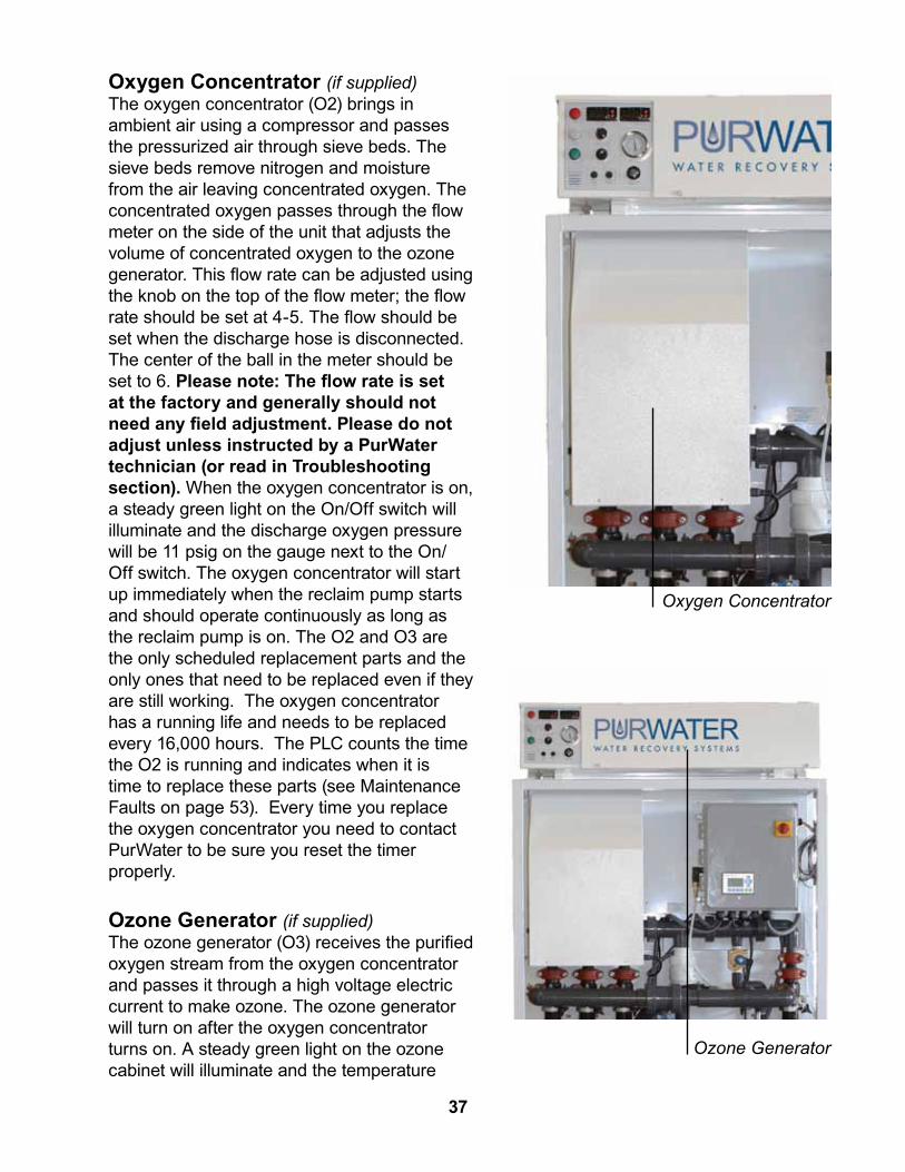
Oxygen Concentrator (if supplied)The oxygen concentrator (O2) brings in ambient air using a compressor and passes the pressurized air through sieve beds. The sieve beds remove nitrogen and moisture from the air leaving concentrated oxygen. The concentrated oxygen passes through the flow meter on the side of the unit that adjusts the volume of concentrated oxygen to the ozone generator. This flow rate can be adjusted using the knob on the top of the flow meter; the flow rate should be set at 4-5. The flow should be set when the discharge hose is disconnected. The center of the ball in the meter should be set to 6. Please note: The flow rate is set at the factory and generally should not need any field adjustment. Please do not adjust unless instructed by a PurWater technician (or read in Troubleshooting section). When the oxygen concentrator is on, a steady green light on the On/Off switch will illuminate and the discharge oxygen pressure will be 11 psig on the gauge next to the On/Off switch. The oxygen concentrator will start up immediately when the reclaim pump starts and should operate continuously as long as the reclaim pump is on. The O2 and O3 are the only scheduled replacement parts and the only ones that need to be replaced even if they are still working. The oxygen concentrator has a running life and needs to be replaced every 16,000 hours. The PLC counts the time the O2 is running and indicates when it is time to replace these parts (see Maintenance Faults on page 53). Every time you replace the oxygen concentrator you need to contact PurWater to be sure you reset the timer properly.
Ozone Generator (if supplied)The ozone generator (O3) receives the purified oxygen stream from the oxygen concentrator and passes it through a high voltage electric current to make ozone. The ozone generator will turn on after the oxygen concentrator turns on. A steady green light on the ozone cabinet will illuminate and the temperature
Oxygen Concentrator
Ozone Generator
37

switch display(s) will turn on when the generator is on. If no faults are present, 15 seconds after power is on a blue light will illuminate when it is making ozone. The blue light on the ozone cabinet will be lit and get more or less bright as the potentiometer switch is adjusted to make more or less ozone. The ozone generator will not operate unless there is enough inlet pressure from the oxygen concentrator (a min. of 7-8 psig).
The inlet pressure is adjusted using the needle valve and is shown by the gauge on the ozone cabinet - do not close this valve all the way. Also, the ozone generator will only operate if there is enough vacuum draw from the Mazzei eductor, the ozone cell
Mazzei EductorThe vacuum created by the Mazzei eductor draws ozone in from the ozone generator to mix with the recirculation water going back to the reclaim tanks. If there is not enough vacuum draw, the ozone generator will not operate.
Inlet(marked on body)
Outlet(marked on body)
Ozone InletTubing Connection
Mazzei check valve
Plumbing / Misc Components
temperature is below 150 degrees Farenheit and the internal ozone diagnostics are satisfied. The ozone generator will operate continuously when all of these conditions are met. The ozone generator has a running life and needs to be replaced every 16,000 hours. The PLC counts the time the O3 is running and indicates when it is time to replace these parts. Every time you replace the cell(s) you need to contact PurWater to be sure you reset the timer properly.
38

Sparger (if supplied)If the reclaim does not have ozone, it comes equipped with an air sparger which is located in the second chamber of the first tank. The sparger draws in air through the top port to mix oxygen with the reclaim water which aerates the water to control the anaerobic bacteria growth in the reclaim tanks. The sparger operates continuously, whether the system is washing cars or recirculating, as long as the pump is running.
Cyclonic SeparatorsAll 5 micron reclaims come with one or more cyclonic separators, or cyclones, for short. The cyclones take the water at the inlet in the middle, spin the water in a vortex forcing the heavy material (solids) to the bottom and the lighter material (water) to the top, which becomes the product water and also the water that gets recirculated back to the first tank.
AIr Sparger Assembly
Cyclonic Separator
Air Sparger Assembly
39

40

OffOff is the mode the system starts in whenever the Siemens LOGO is powered off and then back on. It is also the mode it is locked in if the time and date are not set on the HMI. For instructions on setting the clock go to Start-Up on page 25. The Startup menu is the first screen that comes up when power is applied and the clock is set on the PLC. The Startup menu can also be accessed by pressing F2 (Off) in the default Off screen which is the first screen displayed when the system is taken out of Hand or Auto. You can exit Off mode whether you are in the setup menu or not at any time by pressing Hand or Auto. When in the startup menu if there are no buttons pressed for two minutes the program rolls back to the default message shown below. Please note: You must press and hold the buttons on the HMI firmly and release only after you see the display change on the screen.
System off Auto=Pump
Hand=Bypass F2=Startmenu
System off Auto=Pump
F4=Reset the basket timer
Default Off Message Default Off Message Scrolled
In the default off screen you can either enter the Startup menu or clear the basket strainer timer. Press F2 (Off) to enter the Startup Menu, press F4 (Prime) if you just cleaned the basket strainer to reset the timer. Please visit the Startup Menu on page 25 for help navigating through the options in Off mode.
The function of each mode and the purpose they serve are as follows:
Please note: Buttons are called out sometimes as F1 F2 F3 and F4. They are called out by their F numbers when they are not used for their primary functions. Example: Press F3 in Auto mode; the system is already in Auto, the button then serves as a different function, F3. However, Off and Hand still will serve as Off and Hand if the system is in Auto. It is not necessary to hold ESC or OK when pressing these buttons to make them F#. The prime button is called out as Prime only when it is used to prime the system, all other times it is F4. Press and hold Hand Off Auto and Prime buttons firmly until you see desired action or change in screen. When scrolling through menus wait 5 seconds between pressing buttons. An easy way to be sure of the time is to wait until prompted to press a button by the HMI. If the system is left in any screen other than the default for two minutes without a button being pressed, the program will revert it back to the default screen for that mode.
Operating the Reclaim Unit
41

Hand In hand the reclaim will open the bypass solenoid when a car wash activation is sent to the reclaim panel. Hand is the mode that you would turn the system to if the reclaim water was unavailable for use in the wash. Some examples of when you would run in Hand is if you had a seal burn out on the reclaim pump and could not run the pump without flooding the equipment room, if you had a critical part on the system fail and you were waiting for a replacement, or if there were an ozone system failure and the odor of the reclaim water had become unbearable while waiting for replacement parts. There is no sub-menu in Hand and the screen does not scroll. In Hand the HMI screen looks like this:
Hand Mode:Wash Act OffBypass on ifWash act on
Hand Mode:Wash Act OnBypass on ifWash act on
Hand w/o Wash Active Hand w/ Wash Active
The wash act on/off section is for the operator to quickly determine if the bypass should be energized or not, speeding along the troubleshooting process should it be required.
AutoAuto is the mode the system needs to be in to operate the pump and all other applications included with the system. Faults only register on the HMI in Auto as they are irrelevant in Off or Hand. If no major faults are active the pump will run constantly. If there is ozone on the system it will run in Auto if no faults with the pump system or ozone system are present. All faults are displayed on the HMI and are prioritized to show in sequence of importance. For example, if the VFD is faulted and the recirc ball valve is out of position, the HMI will display the VFD fault and disregard the ball valve fault until the VFD problem is fixed. Every morning at 2 AM the system will run the underflow flush (or U/F flush) if the pump is running. The first Auto screen that will display if there are no faults will be:
Auto: Press prime now if you need to
prime system
When you see this screen you can press prime to begin the priming mode.
42

After the press prime screen, if still no faults are present you will see this screen:
Auto: Systemruns 24/7 if not faulted
Wash Act Off
Or this one if there is a carwash activation present:
Auto: Systemruns 24/7 if not faulted
Wash Act On
From here you can navigate through the Auto submenu to run the underflow flush, shown on the HMI screen as a U/F flush. You can also view the system add-ons such as the ozone, AOS, trench flush, or chain rinse. To learn more about navigating through the Auto Submenu go to page 33. To learn more about faults, causes and fixes visit the Troubleshooting section on page 53.
43

ExtrasAqualinks (AOS) The Aqualink (also known as AOS) is an add on system to help improve the quality of the recirculation water. The AOS system operates a chemical pump injecting a peroxide solution into the bio-ball system helping to break down the soap and surfactants. The addition of the peroxide helps the remains of the bacteria the ozone has killed to drop out improving the overall visual quality of the reclaim water. The AOS operates whenever the system is in Auto and the pump is running.
Trench FlushThe trench flush is an optional solenoid controlled by the PLC. It will help keep the trench clear of solids it runs for a default 45 seconds after the wash signal is turned off to the reclamation system.
Chain RinseThe chain rinse is also an optional solenoid controlled by the PLC which runs when the pump is running and the wash is active to rinse off the chain of the tunnel conveyor. It is designed to keep debris from collecting on the chain. It can help prolong the life of the conveyor chain.
44
Maintenance Task Daily Weekly Monthly Quarterly Every 6 Mos. Every 12-18 Mos. Est. Time RequiredFOR ALL PW UNITSCheck HMI Screen • <1 MinCheck Pump Pressure • <1 MinClean Basket Strainer • <1 Min
Verify Flow Through U/F valve • <1 MinPump Out Settling Tanks • 1 dayFOR OZONE UNITSVerify Ozone Production (Blue Light) • 5 Min
Clean Oxygen Concentrator and Ozone Generator Filters
• 5 Min
Clean the Mazzei Eductor • 10 Min
Replace Oxygen Concentrator and Ozone Cells
• 60 Min
FOR SPARGER UNITSCheck Sparger Operation • 5 MinRemove and Clean Sparger • 30 Min
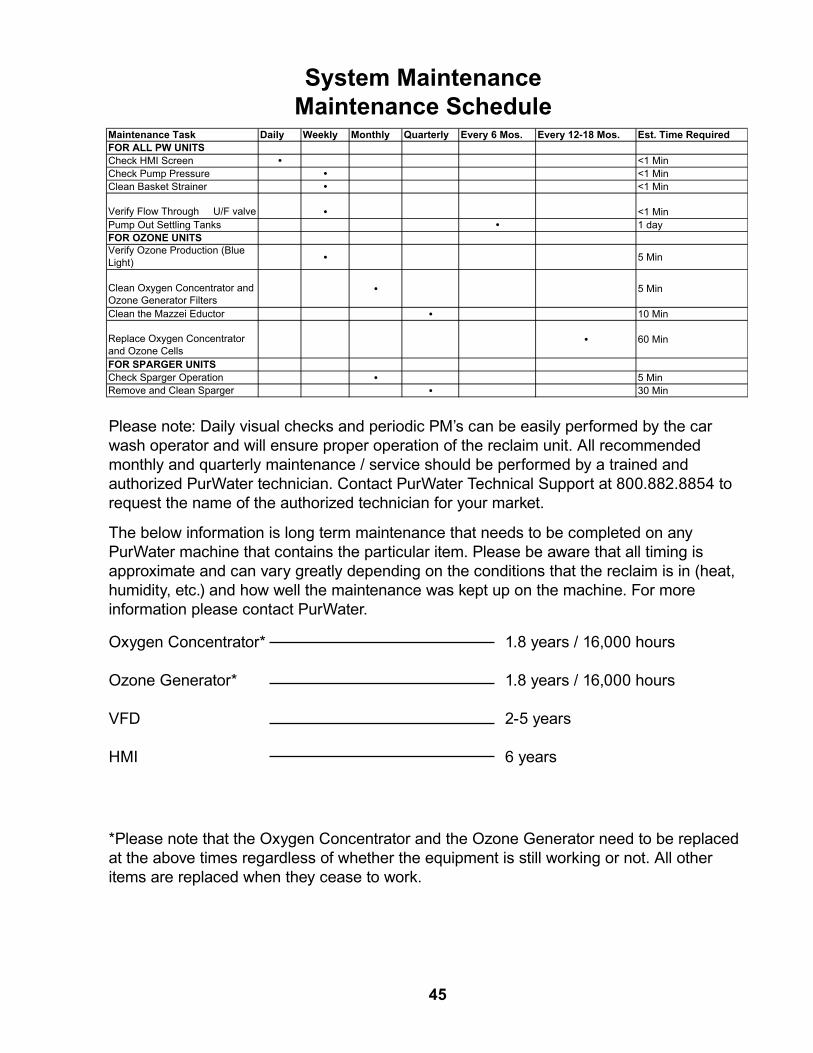
System MaintenanceMaintenance Schedule
Please note: Daily visual checks and periodic PM’s can be easily performed by the car wash operator and will ensure proper operation of the reclaim unit. All recommended monthly and quarterly maintenance / service should be performed by a trained and authorized PurWater technician. Contact PurWater Technical Support at 800.882.8854 to request the name of the authorized technician for your market.
The below information is long term maintenance that needs to be completed on any PurWater machine that contains the particular item. Please be aware that all timing is approximate and can vary greatly depending on the conditions that the reclaim is in (heat, humidity, etc.) and how well the maintenance was kept up on the machine. For more information please contact PurWater.
Oxygen Concentrator*
Ozone Generator*
VFD
HMI
1.8 years / 16,000 hours
1.8 years / 16,000 hours
2-5 years
6 years
*Please note that the Oxygen Concentrator and the Ozone Generator need to be replaced at the above times regardless of whether the equipment is still working or not. All other items are replaced when they cease to work.
45

Check HMI Screen• If possible, to avoid running in bypass mode for prolonged periods of time without realizing it, take a quick look at the HMI screen. • If the screen is not flashing there is no fault that needs to be addressed. • If the screen is flashing, press F3 to see the fault message that is displayed.
Note: If you can not tell if the screen is flashing press F3 to be sure. Check the troubleshooting section for a better understanding of the cause and solution of the fault messages.
Check Pump Pressure• The pump pressure gauge should show pressure when the motor is running. • This pressure will vary depending upon whether the wash is on or not and the mode of operation of the reclaim unit. - In the low frequency recirculation mode the pressure should be about 15-20 psig - At higher pump speeds, when there is a demand signal from the car wash, the pump pressure may read as high as 50-55 psig. • If there is no pressure please turn to the Troubleshooting section on page 53.
Pump pressure gauge:
15-55 psig depending on Wash Activation
46

Clean Basket Strainer • Turn the system to Hand mode. This will put the system in bypass mode so that the wash does not need to be closed. • Loosen the dogear bolts holding down the strainer basket housing lid. • Remove one of the two dogear bolts closest to you. • Rotate the strainer basket housing lid counter clockwise and slide the lid off the strainer basket housing. • If the lid does not rotate or slide, remove all the dogear bolts and gently pry the lid from the strainer basket housing. • Reach into the housing, grasp the strainer basket handle and twist the basket enough to break it free in the event it is lodged. Lift the strainer basket in a twisting motion and remove it from the housing. • Remove and properly dispose of any large particulates that may have accumulated in the strainer basket. • Rinse the basket with fresh water. • Once the basket is clean, replace the basket into the housing. • Inspect basket strainer lid O-Ring for debris. • Replace the lid and the dogear bolts. • Tighten the dogear bolts in a cross pattern to ensure the strainer basket housing lid is evenly seated on the housing. • Press Off, when screen says F4= Reset basket timer press F4 for 2 seconds • When you press F4 the screen will say you have reset the basket timer.
• If needed, prime the pump (See page 28 ).
Basket Strainer with on ‘dog ear’ removed and lid rotated for
removal
Basket Strainer lid removed
Strainer basket being removed
Basket Strainer with one dogear bolt removed and
lid rotated for removal
Basket Strainer lid removed
Basket Strainer being removed
47

Verify Flow Through U/F Valve• Verify underflow is not backed up by loosening the front side union while the pump is running in Auto. • If you have a slight stream going through the valve, that is all you need to do. • If there is no flow, force a U/F flush (See auto sub) and once the U/F flush is finished, repeat. • If the U/F flush did not break the solids free, turn the system to Hand, disconnect the entire valve by loosening both unions and find out where the blockage is.• This is important because if solids get trapped behind the valve for too long it can clog up the cyclones and be extremely difficult to impossible to unclog.
U/F Flush Valve with Water Flowing Through
Pump Out Settling Tanks• Call a company that pumps out septic tanks and have them pump out the tanks.• For best results, wash tank walls down while empy and have the septic company pump that out too. • If possible, use the time the tanks are empty to inspect foot valves and recirc line.• Refill tanks before turning the system back to Auto.
48

Verify Ozone Production (Blue Light)With the power on and the system operating in Auto, check for ozone production (blue light should be illuminated). • Remove the manhole cover over the underground reclaim tank where ozone gas is injected. An odor of ozone should be present.
Caution: Inhaling concentrated ozone can create severe breathing problems. Precautions must be made to prevent exposure to concentrated ozone.
Clean Oxygen Concentrator and Ozone Generator FiltersWith the power On and system operating in Hand: • Remove the air filters on the oxygen concentrator and ozone generator. - To remove the filter from the ozone unit, first remove the outer filter housing to expose the filter for removal. Do not reach into the fan. - The filter for the oxygen unit can be removed by gently pulling the filter element from the side of the oxygen concentrator. • Shake the filters or use dry air to blow the dirt out of the filters. If needed, the filters can be washed with mild detergent and water, but they need to be completely dry before reinstalling. • Reinstall the filters.If either filter element becomes frayed or damaged, replace immediately. Contact PurWater for replacements.
Disregarding maintenance of these filters will result in the system overheating and possible failure.
Oxygen Concentrator Air FilterOzone Generator Filter (one on each side)
Ozone Output Light:illuminated to show ozone
production
49
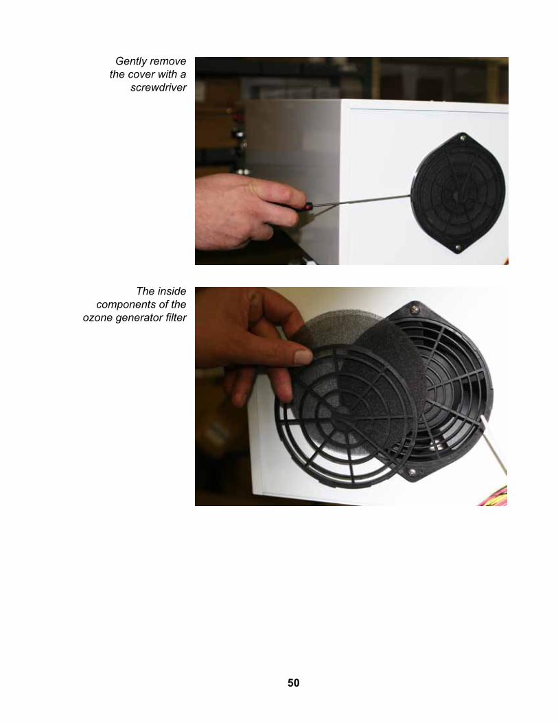
Gently remove the cover with a
screwdriver
The inside components of the
ozone generator filter
50

Clean the Mazzei Eductor • Turn the system into Hand mode. This will put the system in bypass mode so that the wash does not need to be closed. • Remove the Mazzei eductor from its unions. • Visually inspect both the body of the Mazzei eductor and the nozzle / ball check valve assembly to ensure that it is not clogged. Clean if necessary and replace the check valve components. • Replace the Mazzei eductor and ensure that the inlet end (marked on the body) is pointed up.
Please note: When removing the cap from the Mazzei eductor nozzle / ball check assembly be careful not to lose the plastic seat, ball and spring. The spring is compressed and may have enough force to launch the plastic seat and ball and spring free from the Mazzei body when the nozzle cap is removed.
Venturi throat Mazzei Eductor
nozzle/ball check valve assembly
Mazzei Venturi Throat Mazzei Eductor Assembly
Nozzle / Ball Check Valve Assembly
Inside the Mazzei
Eductor Body
Replace the Oxygen Concentrator and Ozone Cells • Every 18-24 months, the oxygen concentrator and ozone cells will need to be replaced with rebuilt components. - The oxygen concentrator will need to be removed in its entirety from the frame and replaced with a rebuilt concentrator. - The ozone cells will need to be removed and replaced with rebuilt cells. • Contact PurWater regarding our rebuild program to exchange the concentrator and cells with factory rebuilt products. • Please note that both of these should be changed at the same time.
51

Check Sparger Operation • Remove the manhole cover over the underground reclaim tank where the sparger is located. • Check to see if there is a stream of water flow from the end of the sparger mixing tube. • Place your finger over the air intake port on top of the sparger and check for suction. • Clean the sparger if there is no stream of water from the end of the mixing tube or if there is no suction from the air intake. (See next section.)
Remove and Clean Sparger • Put the system into Hand mode. This will put the system in bypass mode so that the wash does not need to be closed. • Remove the sparger assembly from the tank by sliding the assembly out of the wall bracket and disconnecting the recirculation water inlet at the union. • Check the air intake port on the sparger and ensure it is not clogged. Flush with water to clear any debris . • Check the recirculation water inlet and ensure it is not clogged. Flush with water to clear any debris. • Check the sparger nozzle outlet and ensure it is not clogged. Flush with water to clear any debris. • If flushing with water does not clear the debris, the air intake and sparger nozzle pieces can be removed from the main sparger body for better cleaning access. • Before attaching the cleaned air sparger, prime the reclaim system and allow it to run for 1-2 minutes to flush out the recirculation line between the reclaim unit and the tank. • Again, place the system in Hand mode. Re-install the sparger onto the wall bracket and replace the recirculation line plumbing. Be sure the top air intake port is not obstructed. • Re-prime and restart the reclaim system. Check that the sparger is flowing water and drawing air.
Air Sparger Assembly
Air Intake Opening (on top)
Air Intake Sparger Body
Sparger Nozzle
Air Intake
SpargerBody
Sparger Nozzle
52

The PurWater 2.0 Reclaim System was designed with easy troubleshooting in mind. The first step is typically to determine what the HMI says. If the screen is flashing, press and hold F3 briefly and the screen will stop flashing. All faults are displayed on the HMI and are prioritized to show in sequence by importance. For example, if the VFD is faulted and the recirc ball valve is out of position, the HMI will display the VFD fault and disregard the ball valve fault until the VFD problem is fixed. From there, read the message and then find the cause and solution on the next few pages. If the screen is not displaying a fault, go to page 68.
System Troubleshooting
53
When contacting PurWater’s Technical Support department, it is often necessary to have your PurWater serial number available. On the Pro Series systems, the serial number is located in the middle of the frame between the contol box and the oxygen concentrator.
Pro Series serial number
location

54
Maintenance FaultsMaintenance faults are not technically faults in that they do not necessarily indicate a problem. Instead, it is indicative of an action required or a warning of upcoming maintenance needed. Looking just like a fault, the screen will flash and you can press F3 to stop the screen from flashing to read the fault. Maintenance faults only appear in Auto.
Please clean basket then press F4 in Off to reset
Cause: This is the most common of the maintenance faults and is simply a reminder to clean or check the basket strainer once a week. There is a default of 168 hours of the pump running, equal to 7 days. This is a conservative number but it is always best to check the basket too often rather than not often enough. Even if the basket is clean to start with, over time the basket will inevitably need to be cleaned more often between the tanks being freshly
Solution: Clean the basket strainer (see maintenance page 47). After cleaning the basket, remember to press F4 in the default Off screen (see below) and the timer will be reset.
F4 not pressed
pumped out and as the date approaches of them needing to be pumped out again.
System offAuto = PumpBasket timeris now reset
System off Auto=Pump
F4=Reset the basket timer
F4 pressed

O2/O3 half life warning8XXX hoursF3 5 secs to
Cause: The purpose of the reminder is so that someone is aware (or otherwise notified when the fault shows up) that the ozone and oxygen components will require replacing at 16000 hours. Note: The 8XXX indicates what will most likely be showing, as the fault comes on at 8000 hours and does not go away without being acknowledged.
Solution: The oxygen and ozone half life fault requires no other action other than to press and hold the F3 (Auto) button for five seconds to be cleared.
O2/O3 fulllife warning16XXX hoursCheck manual
Cause: The oxygen and ozone full life indicates that it is time to replace the oxygen concentrator and the ozone cells. The fault cannot be acknowledged until the parts are replaced.
Solution: Contact PurWater or your PurWater distributor for information on ordering the parts and how to clear this maintenance fault once the parts have been installed.
55

Minor System FaultsAll minor system faults are relevant to the motorized ball valve positions. The 2” is referred to as the recirc, both on the HMI and in the troubleshooting guide. The 1” ball valve is referred to as the underflow or U/F valve, but only the U/F valve on the HMI. The minor system faults can cause a lack of water to the wash or through the recirc line, but will not disable the reclaim pump.
U/F valve on bottom of machine won’t open
Cause: The 1” valve on the underflow is or was out of position. Locate the view port (see photo) and determine if the valve is currently open or closed. Note: Unless it is 2 AM, the clock is set wrong, or someone just tried to force the U/F flush via the Auto submenu this valve should be closed.
Solution: After checking view port, if the valve is closed (red for closed) press F4. This will clear the fault. Wait 10 seconds to see if fault reappears. If it does not, force an underflow flush through the Auto submenu (see page 33 or 76) and check the view port to see if the valve opens. If it does open (green for open) check the HMI to see if fault comes back. If fault comes back and the valve is opening, contact PurWater for further assistance.
If the valve does not open, turn the system to Hand to place it in bypass and remove valve by loosening the two unions. Inspect the valve for debris built up on or in it, also check the underflow line to see if there are solids backed up there. If the wash can be briefly shut down from washing cars go to Off mode, then through the startup menu
and try to force the valve open while disconnected from the plumbing. If it still will not open, contact PurWater for further assistance. If the valve will open when disconnected from the plumbing, after it closes re-attach it to the plumbing and try again. If it does open, turn the system back to Auto and try it again under pressure through the Auto submenu.
Valve Motor
56

U/F valve on bottom of machine wont close
Cause: The 1” valve on the underflow is or was out of position. Locate the view port (see photo) and determine if the valve is currently open or closed. Note: Unless it is 2 AM, the clock is set wrong, or someone just tried to force the U/F flush via the Auto submenu this valve should be closed.
Solution: After checking view port, if the valve is open (green for open) and should not be press Hand to place the system in bypass mode and remove valve by loosening the two unions. Inspect the valve for debris built up on or in it, also check the underflow line to see if there are solids backed up in the line. If removing the valve from the underflow line does not close it, remove the two bolts that hold the motor to the valve. Unbolt the motor and try to force the valve closed by hand. Note: This will most likely turn the motor portion to the correct closed position, when it’s time to re-attach to try and close valve you will need to go to Off Startup
Menu and force the motor to line up with the valve. If possible, spray the valve portion once disconnected with a pressure washer gun or blow compressed air through plumbing and orifice hole. After cleaning, go to Startup menu and force motor to line up with valve, re-attach and see if it will now open.If it does not, unbolt the motor and try to force the valve closed by hand. If it still will not close, contact PurWater for further assistance. If at any point the valve closes when disconnected from the plumbing, re-attach it to the plumbing and force a U/F flush (see auto submenu) to be sure it opens and closes properly on its own.
U/F Valve View Port: Red for Closed (top) Green for Open (bottom)
Valve and collar must line up before reattaching (top).Blowing compressed air through valve (left)
Use 7/16” wrench and socket (front and back) to disassemble valve from motor
57
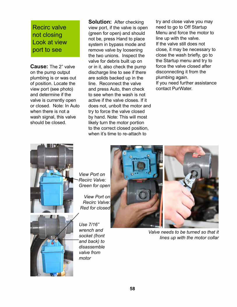
Recirc valve not closingLook at viewport to see
Cause: The 2” valve on the pump output plumbing is or was out of position. Locate the view port (see photo) and determine if the valve is currently open or closed. Note: In Auto when there is not a wash signal, this valve should be closed.
Solution: After checking view port, if the valve is open (green for open) and should not be, press Hand to place system in bypass mode and remove valve by loosening the two unions. Inspect the valve for debris built up on or in it, also check the pump discharge line to see if there are solids backed up in the line. Reconnect the valve and press Auto, then check to see when the wash is not active if the valve closes. If it does not, unbolt the motor and try to force the valve closed by hand. Note: This will most likely turn the motor portion to the correct closed position, when it’s time to re-attach to
try and close valve you may need to go to Off Startup Menu and force the motor to line up with the valve. If the valve still does not close, it may be necessary to close the wash briefly, go to the Startup menu and try to force the valve closed after disconnecting it from the plumbing again. If you need further assistance contact PurWater.
View Port on Recirc Valve:
Red for closed
View Port on Recirc Valve: Green for open
Valve needs to be turned so that it lines up with the motor collar
Use 7/16” wrench and socket (front and back) to disassemble valve from motor
58

Recirc valve not openingLook at viewport to see
Cause: The 2” valve on the pump output plumbing is or was out of position. Locate the view port (see photo) and determine if the valve is currently open or closed. Note: In Auto when there is not a wash signal, this valve should be closed.
Solution: After checking view port, if the valve is closed (red for closed) and should not be press Hand to place system in bypass mode and remove valve by loosening the two unions. Inspect the valve for debris built up on or in it, also check the pump discharge line to see if there are solids backed up in the line. If removing the valve from the line does not open it, remove the two bolts that hold the motor to the valve. Note: This will most likely turn the motor portion to the correct open position, so when it’s time to re-attach to try and close valve you will need to go to Off Startup Menu and force the motor to line up with the valve.
If possible, spray the valve portion once disconnected with a pressure washer gun or blow compressed air on both sides of the valve. After cleaning, try to force the valve open by hand. If it still will not open, go to Startup menu and force motor to line up with valve, re-attach and see if it will now open. If it still will not open, contact PurWater for further assistance. If at any point the valve opens when disconnected from the plumbing, re-attach it to the plumbing and verify it closes and opens properly with the system running.
View Port on Recirc Valve:
Red for closed
View Port on Recirc Valve: Green for open
59
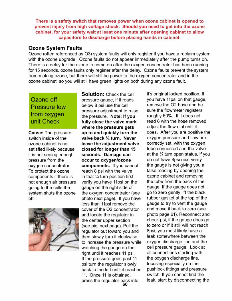
There is a safety switch that removes power when ozone cabinet is opened to prevent injury from high voltage shock. Should you need to get into the ozone cabinet, for your safety wait at least one minute after opening cabinet to allow
capacitors to discharge before placing hands in cabinet.
Ozone System FaultsOzone (often referenced as O3) system faults will only register if you have a reclaim system with the ozone upgrade. Ozone faults do not appear immediately after the pump turns on. There is a delay for the ozone to come on after the oxygen concentrator has been running for 15 seconds, ozone faults only register after the delay. Ozone faults prevent the system from making ozone, but there will still be power to the oxygen concentrator and in the ozone cabinet, so you will still have green lights on both during any ozone fault.
Ozone off Pressure low from oxygen unit Check
Cause: The pressure switch inside of the ozone cabinet is not satisfied likely because it is not seeing enough pressure from the oxygen concentrator. To protect the ozone components if there is not enough air pressure going to the cells the system shuts the ozone off.
Solution: Check the cell pressure gauge, if it reads below 8 psi use the cell pressure adjustment to raise the pressure. Note: If you fully close the valve mark where the pressure gets up to and quickly turn the valve back ¼ turn. Never leave the adjustment valve closed for longer than 15 seconds. Damage can occur to oxygen/ozone components. If you cannot reach 8 psi with the valve in that ¼ turn position first verify you have 11psi on the gauge on the right side of the oxygen concentrator (see photo next page). If you have less than 11psi remove the cover of the O2 concentrator and locate the regulator in the center upper section (see pic, next page). Pull the regulator out toward you and then slowly turn it clockwise to increase the pressure while watching the gauge on the right until it reaches 11 psi. If the pressure goes past 11 psi turn the regulator slowly back to the left until it reaches 11. Once 11 is obtained, press the regulator back into
it’s original locked position. If you have 11psi on that gauge, remove the O2 hose and be sure the flowmeter registers roughly 60%. If it does not read 6 with the hose removed adjust the flow dial until it does. After you are positive the oxygen pressure and flow are correctly set, with the oxygen tube connected and the valve at the ¼ turn open status, if you do not have 8psi next verify the gauge is not giving you a false reading by opening the ozone cabinet and removing the tube from the back of the gauge. If the gauge does not go to zero gently lift the black rubber gasket at the top of the gauge to try to vent the gauge and move it back to zero (see photo page 61). Reconnect and check psi, if the gauge does go to zero or if it still will not reach 8psi, you most likely have a leak somewhere between the oxygen discharge line and the cell pressure gauge. Look at all connections starting with the oxygen discharge line, focusing especially on the pushlock fittings and pressure switch. If you cannot find the leak, start by disconnecting the
60

oxygen inlet pushlock fitting on the bottom left hand side of the ozone cabinet and putting your finger over the end of it, watch the ball on the oxygen flowmeter and watch to see if it drops to zero. Do not cut off flow for more than 15 seconds at a time. If the ball drops to zero, move on to the next fitting, disconnect and see if the ball drops to zero with your finger over it until you find the leak.
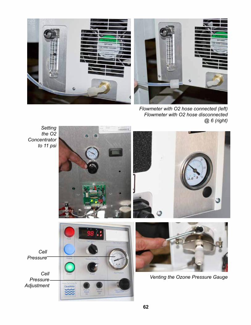
Flowmeter with O2 hose connected (left)Flowmeter with O2 hose disconnected
@ 6 (right)Setting the O2
Concentrator to 11 psi
Cell Pressure
Cell Pressure
Adjustment
62
Venting the Ozone Pressure Gauge
Ozone off No vacuum at black mazzei inject point
Cause: The vacuum switch is registering that there is not enough vacuum from the mazzei eductor to run the ozone generator. As water runs through the mazzei, it creates a vacuum to draw in ozone, if it fails to do so the system shuts down ozone production.
Solution: Check cell pressure is 8 psi and pump pressure is above 15 psi. Remove the ozone line from the mazzei at the stainless steel compression fitting. Put your finger over the hole and see if it is pulling any vacuum (see photo next page). If it is pulling vacuum go to Step 2 (below). If it is not, turn the system to bypass by pressing hand, disassemble the suction portion (See maintenance, page 45) check for debris and clean. After cleaning, verify the flow arrow is pointing downward when re-attaching and try again. If still no vacuum on the suction port verify there is good water
flow through the mazzei by disconnecting the bottom union and turning it so the outlet of the mazzei can free flow onto the floor. While free flowing onto the floor, check the suction port and see if it is pulling vacuum. If so, there is blockage downstream on the recirc line and it may require pumping out the tanks. If it is still not pulling in vacuum it will be necessary to replace the mazzei.
Step 2If you are getting good vacuum at the mazzei but still getting the no vacuum fault locate the stainless steel check valve up in the ozone cabinet near to the right hand cooling fan. Disconnect the inlet compression fitting (the one closer to the front of the machine) and feel if the same vacuum is pulling through the check valve. If no, remove the check valve, run a small piece of wire through it, reconnect and run same test again. If the check valve will not work correctly, replace it. If you are getting good suction through the check valve, re-attach and try to run ozone again.
If you are getting good vacuum all the way through the check valve and are still getting the no vacuum fault, it’s time to adjust the vacuum switch. Do so by loosening the brass locking ring, then turning the black part on the left with the cord counter-clockwise ¼ turn and then loosely turning the brass ring tight to avoid it spinning loose. Close the ozone box and see if the fault is still present. If not, try adjusting the switch another ¼ turn. If it does not clear, replace the vac switch. If adjusting the vac switch clears the fault and the blue light comes on, remove the hose from the mazzei to verify it was not adjusted too far and that it will still shut the ozone off if no vacuum is present. If removing the hose does not shut the ozone off, turn the vacuum switch back a little bit until you find a spot the ozone will run when connected and not when disconnected. Contact PurWater for more information.
63

Vaccum Switch
Check Valve
64

Ozone off Temperature trip Check digital temp
Solution: First, verify the temperature switch is displaying above 140 degrees F. If it is not, go to Step 2 (below). If the temperature is above 140 verify that the fans are running, and that the filters are clean and not impeding the fans airflow. If all of that is checked, be sure that the fan blades are not broken, bent or damaged in some way.
Cause: The temperature switch is indicating the temperature is too high so the system has shut down the ozone to protect the ozone components.
Step 2If the temp switch is reading less than 140, verify the setpoint is correct on the temp switch(es). Press and hold the set button on the temp switch for 8 seconds and release when the display changes. The first display will show 0. Press set again, the display will show SP for set point. Press the up or down arrow to make it 140 if it is not already. When done press set and SP will display. Note: If it will not let you set it at 140, go to the other settings first and then go back to SP.
While in the menu scroll though the other settings used by the ozone in the temp switch to verify they are also correct. Press the up arrow once and the display will read Ro. Press set, if it does not show 10, change it to 10 and then press set. Press the up arrow to get to R2 and press set, if it does not show 170 press up arrow until it does and then press set. Up to To, set to 200. Leave screen without pressing anything for 2 minutes to return to the temperature display.
65

Ozone off Fault with components in cabinet
Cause: The circuit board(s) inside the ozone cabinet is sending a signal to the reclaim system indicating there is a fault with one or more of the ozone components. This fault has many possible causes, the two most common causes include if the drive board or control board is faulty.
Solution: Open the ozone cabinet then disconnect the white wire from the drive board (see photo). Either place a wire nut over the white wire or secure it in a way that there is no chance it will arc against the frame. Close the lid on the ozone and see if the ozone fault still exists. If that fixes it the control board is most likely the problem. If it does not,push down safety switch and verify there are two green lights on the power supply and that the ground wires are securely connected. If there is not two green lights on power supply, replace the fuse for the side that is not lit and apply power. Contact PurWater for more info.
White wire from the drive board
Transformer Input
Red Fault Light
66

CellBlack Insulator
Transformer Output
Power Supply
Drive BoardControl Board
Pressure Switch
Power Supply
(green lights)
Control Board
67
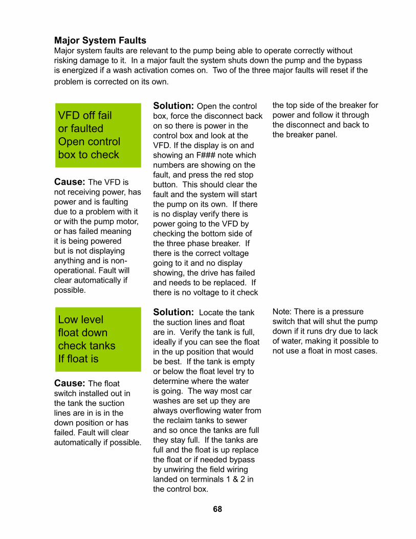
Major System FaultsMajor system faults are relevant to the pump being able to operate correctly without risking damage to it. In a major fault the system shuts down the pump and the bypass is energized if a wash activation comes on. Two of the three major faults will reset if the problem is corrected on its own.
VFD off fail or faulted Open control box to check
Cause: The VFD is not receiving power, has power and is faulting due to a problem with it or with the pump motor, or has failed meaning it is being powered but is not displaying anything and is non-operational. Fault will clear automatically if possible.
Solution: Open the control box, force the disconnect back on so there is power in the control box and look at the VFD. If the display is on and showing an F### note which numbers are showing on the fault, and press the red stop button. This should clear the fault and the system will start the pump on its own. If there is no display verify there is power going to the VFD by checking the bottom side of the three phase breaker. If there is the correct voltage going to it and no display showing, the drive has failed and needs to be replaced. If there is no voltage to it check
the top side of the breaker for power and follow it through the disconnect and back to the breaker panel.
Low level float down check tanks If float is
Cause: The float switch installed out in the tank the suction lines are in is in the down position or has failed. Fault will clear automatically if possible.
Solution: Locate the tank the suction lines and float are in. Verify the tank is full, ideally if you can see the float in the up position that would be best. If the tank is empty or below the float level try to determine where the water is going. The way most car washes are set up they are always overflowing water from the reclaim tanks to sewer and so once the tanks are full they stay full. If the tanks are full and the float is up replace the float or if needed bypass by unwiring the field wiring landed on terminals 1 & 2 in the control box.
Note: There is a pressure switch that will shut the pump down if it runs dry due to lack of water, making it possible to not use a float in most cases.
68
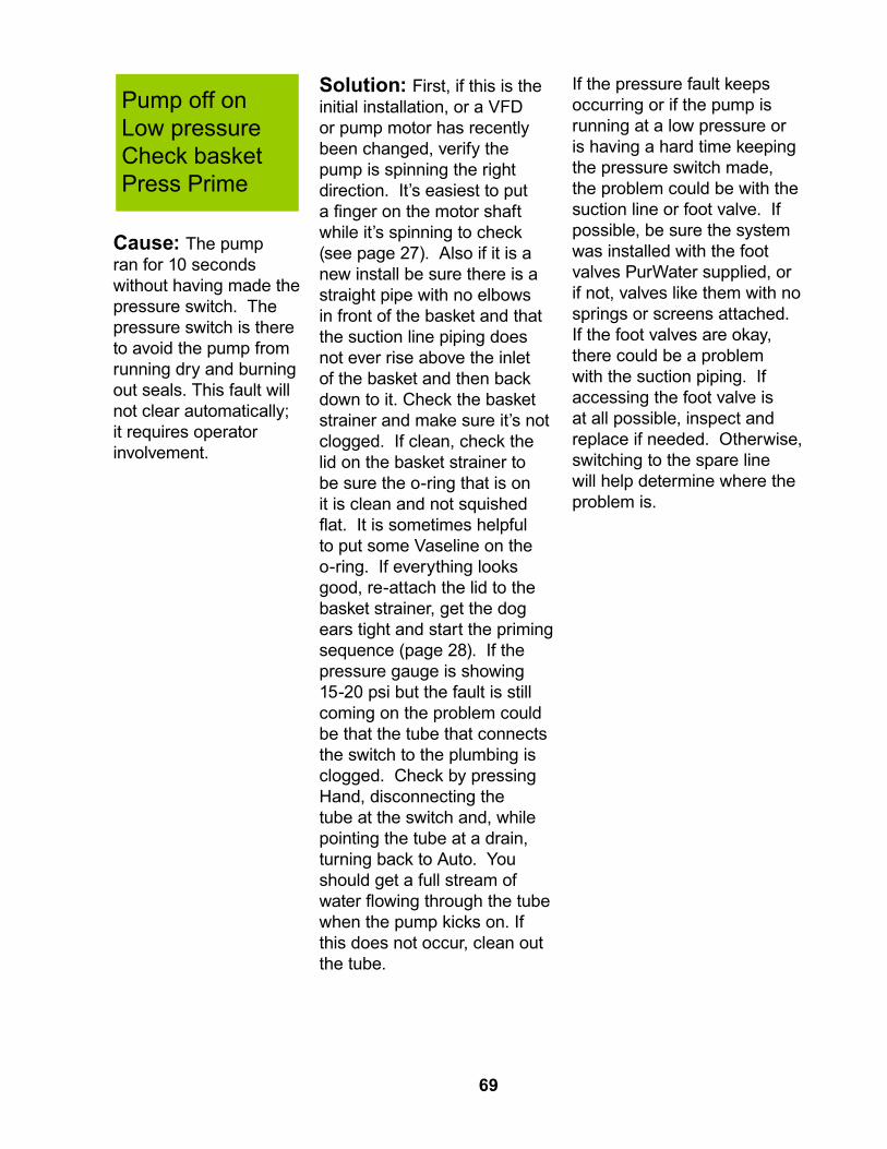
Pump off onLow pressureCheck basketPress Prime
Cause: The pump ran for 10 seconds without having made the pressure switch. The pressure switch is there to avoid the pump from running dry and burning out seals. This fault will not clear automatically; it requires operator involvement.
Solution: First, if this is the initial installation, or a VFD or pump motor has recently been changed, verify the pump is spinning the right direction. It’s easiest to put a finger on the motor shaft while it’s spinning to check (see page 27). Also if it is a new install be sure there is a straight pipe with no elbows in front of the basket and that the suction line piping does not ever rise above the inlet of the basket and then back down to it. Check the basket strainer and make sure it’s not clogged. If clean, check the lid on the basket strainer to be sure the o-ring that is on it is clean and not squished flat. It is sometimes helpful to put some Vaseline on the o-ring. If everything looks good, re-attach the lid to the basket strainer, get the dog ears tight and start the priming sequence (page 28). If the pressure gauge is showing 15-20 psi but the fault is still coming on the problem could be that the tube that connects the switch to the plumbing is clogged. Check by pressing Hand, disconnecting the tube at the switch and, while pointing the tube at a drain, turning back to Auto. You should get a full stream of water flowing through the tube when the pump kicks on. If this does not occur, clean out the tube.
If the pressure fault keeps occurring or if the pump is running at a low pressure or is having a hard time keeping the pressure switch made, the problem could be with the suction line or foot valve. If possible, be sure the system was installed with the foot valves PurWater supplied, or if not, valves like them with no springs or screens attached. If the foot valves are okay, there could be a problem with the suction piping. If accessing the foot valve is at all possible, inspect and replace if needed. Otherwise, switching to the spare line will help determine where the problem is.
69

Troubleshooting Without a Fault on the HMI
Not enough water going out to feed wash
Check to see what the VFD is displaying while feeding car wash. During wash, the VFD operates based on the product line pressure. Using the transducer it tries to maintain 40 psi on the line. If the product line is displaying less than 40 psi, the VFD should be showing 60.0 hz. If so, contact PurWater for more info on the flows you can expect to get from that particular model.
Water smells Verify there is a check valve on the sewer discharge line to prevent sewage from backing up into the reclaim tanks. If the tanks have not been pumped out in the last 6 months it is time to pump them out.If sparger unit, see below. If ozone unit, is the blue light on up at the ozone cabinet? If not, open and inspect ozone cabinet for a blown fuse or for other problems. (See fuses blowing below if needed.) If blue light is on, be sure the ozone output is set to 100% and the cell pressure adjustment is not closed all the way shut. With ozone set at 100, the blue light on, and the cell pressure adjustment not fully closed ozone should be entering the tanks on a constant basis. Further check by opening the 2nd compartment of the 1st tank and look for the small ozone bubbles and a slight ozone smell in the tanks.
If the ozone is working but there is still a smell on a single cell (12 gram) ozone system, it is possible to upgrade to a dual cell (24 gram) to double the ozone output. Also, if it is determined that the ozone is working properly and there is still a problem with the water smelling, it is possible to upgrade to an AOS system which will assist the ozone in further removing the reclaim water smell. Contact PurWater for more information about the AOS system and how it works.
The air sparger system does not compare to an ozone system as far as eliminating bacteria growth and smell in the water. If sparger unit, verify sparger is drawing in air like it is supposed to and consider other bacterial management methods. Sparger units are built to be capable of upgrading to an ozone system in the field, contact PurWater for more information.
PurWater AquaLink System (AOS)
70

No display on HMI If the HMI has no display showing, open the cabinet and force the disconnect to the on position to verify the 110v power source is active in the control box. Next, check the two wires on the green connector on the HMI for 24VDC. If you do not have 24VDC at the green connector, check the power supply for a green light and for 24VDC. If there is not 24 volts and no green light on the power supply, replace the power supply. If there is 24 volts to the HMI replace the HMI and contact PurWater for instructions on running the reclaim system without the HMI until the new one arrives.
Ozone fuses blowing
If you have two drive boards determine if one or both fuses are blown. Open the cabinet so the power is removed from the ozone cabinet. Put new fuse in and disconnect the transformer connection on the right (see photo). Close cover which will reapply power in the ozone cabinet. Open cabinet back up and see if the fuse blew with the transformer disconnected. If the fuse did blow, replace the drive board. If the fuse did not blow pull the black insulator up and disconnect the white high voltage cable from the transformer. Set cable in a way it will not arc to transformer or any other electrical connection. Close cover, and see if the fuse blew. If so, replace transformer. If it did not blow, replace the cell.
Transformer connection
Fuse
Drive Board
Green connector on the HMI
Lights illuminated
on the drive board
indicate that the system is creating
ozone (right)
71
Ozone Output Light

VFD FaultsThe VFD has a number of different fault codes that will make it inoperable until the fault is cleared. Some faults the VFD will clear by itself some require the operator to clear manually. If you need to clear a fault manually, first take note of which number the fault code is and then press the red stop button. If the fault no longer exists, the fault will clear and the VFD will turn the pump back on. If the fault is still present pressing the red stop button will not change anything.
These are the faults that are the most likely to be seen on the VFD for a PurWater reclaim system. If you see any other fault code be sure to note the number before resetting. If you are having repeated faults or can not clear one of the faults listed contact PurWater for assistance.
F003Description: Excessive DC bus voltage ripple. Translation: Most likely a problem with the incoming power.Solution: Check incoming power at the bottom of the three phase breaker both to each other and each leg to ground for an inconsistent reading between power legs, a low voltage reading or a reading that jumps around erratically. Contact an electrician if needed.This fault will not automatically reset.
F004Description: Undervoltage fault.Translation: The line power is less than the required power to run the VFD. Note: This fault will appear briefly after the power has been removed from the VFD while the capacitors discharge. Solution: Check incoming power at the bottom of the three phase breaker both to each other and each leg to ground. Contact an electrician if needed.This fault will automatically reset.
F005Description: Overvoltage fault.Translation: The line power is more than the allowed power to run the VFD or the motor is decelerating too fast causing motor regeneration.Solution: Check incoming power at the bottom of the three phase breaker both to each other and each leg to ground. Contact an electrician if needed. If power seems ok, verify that parameter P040 (decel speed 1) is not set below 2.0.This fault will automatically reset.
72
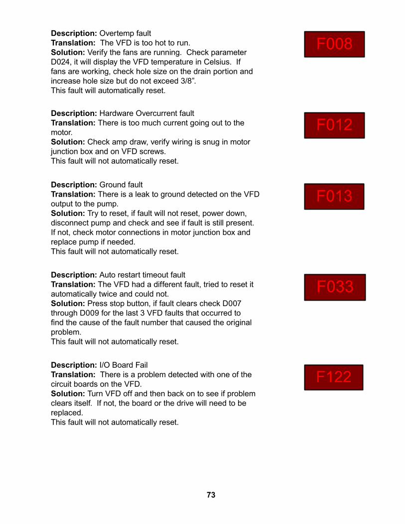
F008Description: Overtemp faultTranslation: The VFD is too hot to run.Solution: Verify the fans are running. Check parameter D024, it will display the VFD temperature in Celsius. If fans are working, check hole size on the drain portion and increase hole size but do not exceed 3/8”. This fault will automatically reset.
Description: Hardware Overcurrent faultTranslation: There is too much current going out to the motor.Solution: Check amp draw, verify wiring is snug in motor junction box and on VFD screws.This fault will not automatically reset.
F012
F013Description: Ground faultTranslation: There is a leak to ground detected on the VFD output to the pump.Solution: Try to reset, if fault will not reset, power down, disconnect pump and check and see if fault is still present. If not, check motor connections in motor junction box and replace pump if needed.This fault will not automatically reset.
F033Description: Auto restart timeout faultTranslation: The VFD had a different fault, tried to reset it automatically twice and could not.Solution: Press stop button, if fault clears check D007 through D009 for the last 3 VFD faults that occurred to find the cause of the fault number that caused the original problem.This fault will not automatically reset.
F122Description: I/O Board FailTranslation: There is a problem detected with one of the circuit boards on the VFD.Solution: Turn VFD off and then back on to see if problem clears itself. If not, the board or the drive will need to be replaced. This fault will not automatically reset.
73

74

Appendix
75

System off Hand=Bypass mode
Auto =Reclaim F2=More info
In Hand or Auto the reclaim will need a
signal from the wash…...
Recirc OpenShould show open If not look at port…...
F2
Wash Act OffWash signal will change status to
on……..
Startup/ Troubleshooting
Tutorial
F2
F4
Run wash/ Watch for status change
F2
F4Press & hold/ check
pump rotation
System off Auto=Pump
Hand=Bypass F2=Startmenu
F4Press & hold for 2 secs after cleaning
basket strainer
F2
In Hand the unit will open the bypass
when the wash act is on……..
If faults occur in Auto display flashes & fault
shows here on…...
F2
F2
Flush Closed Closed? If not look at
port If so……..
Press and hold buttons firmly until you see desired change in screen. Wait 5 seconds
between pressing buttons, an easy way to be sure of the
time is to wait until prompted to press a button by the HMI.
F2
F4If message says
Recirc open press F4 to close for 30 secs
If message says Flush Closed press F4 to open for 30 secs
F2
F4
F4
Off Submenu
76
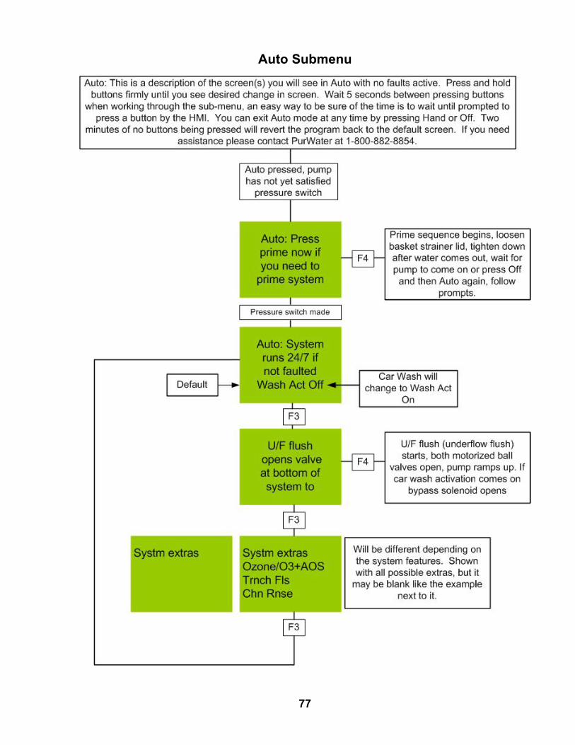
Auto Submenu
77

0 OFF
ABBK 10 AS 201
- 230 / 400
0 OFF0 OFF 0 OFF
ABBS 203K 30 A- 400
3
4
1
2
Bussmann t ON
CDNF32(N)7L
4
(N)8T4
33.9
AB
DC +L1 L2 L3 T1 T2 T3
DC- BR+ BR-
01 02 03 04 05 06 07 08 0911 12 13 14 15 16 17 18 19
R1R2R3
PURWATER STANDARD 5 MICRON RECLAIM CONTROL PANEL VFD CONTROL WIRE CONNECTIONS
01 (OR 11): 24 VDC TO RED TERMINAL STRIP, RED WIRE02: VFD RUN SIGNAL FROM PLC Q1 TERMINAL 2, ORANGE WIRE05: VFD SPEED SIGNAL FROM Q2 TERMINAL 2, ORANGE WIRE14: 24 VDC NEGATIVE TO POWER SUPPLY, BLACK WIRE15: 4-20 MA PRESSURE SIGNAL FROM TRANSDUCER, BLACK WIRER1: 110 VAC TO I1 ON PLCR2: 110 VAC FROM BLACK TERMINAL STRIP
SIEMENS
LOGO!
OUTPUT 4 X RELAY/10A
Q1 Q2 Q4
I5 I6 I7 I8I1 I2 I4I3L1 N
Q3
ESC OK
LOGO!
Q1 Q2
Q4
I1 I2 I4I3L1 N
Q3
RUN/STOP
LOGO!
Q1 Q2
Q4
I1 I2 I4I3L1 N
Q3
RUN/STOP
SIEMENS
L1 N
+ - -
24VDC
110 V AC COMMPrime
O2/O3
Ground
Transducer
78
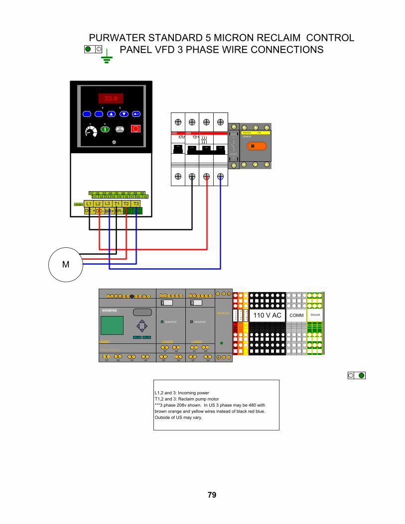
0 OFF
ABBK 10 AS 201
- 230 / 400
0 OFF0 OFF 0 OFF
ABBS 203K 30 A- 400
3
4
1
2
Bussmann t ON
CDNF32(N)7L
4
(N)8T4
33.9
AB
DC +L1 L2 L3 T1 T2 T3
DC- BR+ BR-
01 02 03 04 05 06 07 08 0911 12 13 14 15 16 17 18 19
R1R2R3
PURWATER STANDARD 5 MICRON RECLAIM CONTROL PANEL VFD 3 PHASE WIRE CONNECTIONS
L1,2 and 3: Incoming power T1,2 and 3: Reclaim pump motor***3 phase 208v shown. In US 3 phase may be 480 with brown orange and yellow wires instead of black red blue. Outside of US may vary.
SIEMENS
LOGO!
OUTPUT 4 X RELAY/10A
Q1 Q2 Q4
I5 I6 I7 I8I1 I2 I4I3L1 N
Q3
ESC OK
LOGO!
Q1 Q2
Q4
I1 I2 I4I3L1 N
Q3
RUN/STOP
LOGO!
Q1 Q2
Q4
I1 I2 I4I3L1 N
Q3
RUN/STOP
SIEMENS
L1 N
+ - -
24VDC
110 V AC COMMPrime
O2/O3
Ground
M
79

InputsTerm
inated atD
escriptionC
omm
entsA
ll inputs are 110vacI1
VFD
R1
A positive signal indicating the V
FD is pow
ered on and not faultedI2
Pressure sw
itchA
n absence of signal indicating the pump is running above required pressure
I3A
ctivation relaysA
positive signal indicating one of the three act relays is energizedI4
Recirc ball valve
A positive signal indicating the valve has opened absence indicates closed
Jumper from
terminal 12 on recirc relay if P
W100
I5U
/F ball valveA
positive signal indicating the valve has opened absence indicates closedI6
O2 press sw
itchA
n absence of signal indicating there is enough pressure to run ozone O
nly if ozone suppliedI7
O3 vac sw
itchA
n absence of signal indicating there is enough vacuum at m
azzei to run ozone O
nly if ozone suppliedI8
O3 tem
p switch
An absence of signal indicating the tem
perature is within operating range
Only if ozone supplied
I9O
3 fault indicatorA
n absence of signal indicating the ozone is not faultedO
nly if ozone suppliedI10
FloatA
n absence of signal indicating the water level in the reclaim
tanks is adequateIf installed
I11O
2/O3 Jum
perA
positive signal indicating the reclaim has an ozone upgrade
Only if ozone supplied
I12A
OS
Jumper
A positive signal indicating the reclaim
has an AO
S upgrade
All system
s have receptacle, dry contact in AO
S box activates jum
perI13
Trench flush jumper
A positive signal indicating the reclaim
has an trench flush solenoid upgradeI14
Chain rinse jum
perA
positive signal indicating the reclaim has a chain rinse solenoid upgrade
I15S
pareI16
Future useA
ll outputs close to send power from
terminal 1 to 2 on that Q
number
Outputs
Terminated at
Description
Com
ments
Q1
VFD
02A
positive signal giving the run comm
and to the VFD
24 vdc supplied from V
FDQ
2V
FD 05
A positive signal giving the recirculate com
mand to the V
FD24 vdc supplied from
VFD
Q3-11 110vac from
black terminal strip
Q3
Bypass relay A
1A
n absence of signal giving the bypass the ability to run with a w
ash activationQ
4Y
ellow term
inal stripA
positive signal giving the oxygen concentrator and ozone generator power
Pow
ers ozone but Q5 allow
s ozone productionQ
5O
zone run signalA
positive signal giving the ozone the comm
and to runQ
6O
range terminal strip
A positive siganl giving the prim
e solenoids power
Opens the 3/8" N
C solenoid closes the 1" N
O solenoid
Q7
Recirc valve relay A
1A
positive signal giving the recirc valve close comm
and, absence to openQ
8U
/F valve relay A1
A positive signal giving the U
/F valve open comm
and, absence to closeQ
9A
OS
pump
A positive signal giving the A
OS
pump a run com
mand
Optional A
dd-onQ
10Trench flush solenoid
A positive signal giving the trench flush solenoid an open com
mand
Optional A
dd-onQ
11C
hain rinse solenoidA
positive signal giving the chain rinse solenoid an open comm
andO
ptional Add-on
Q12
Spare
PLC Inputs / O
utputs
80
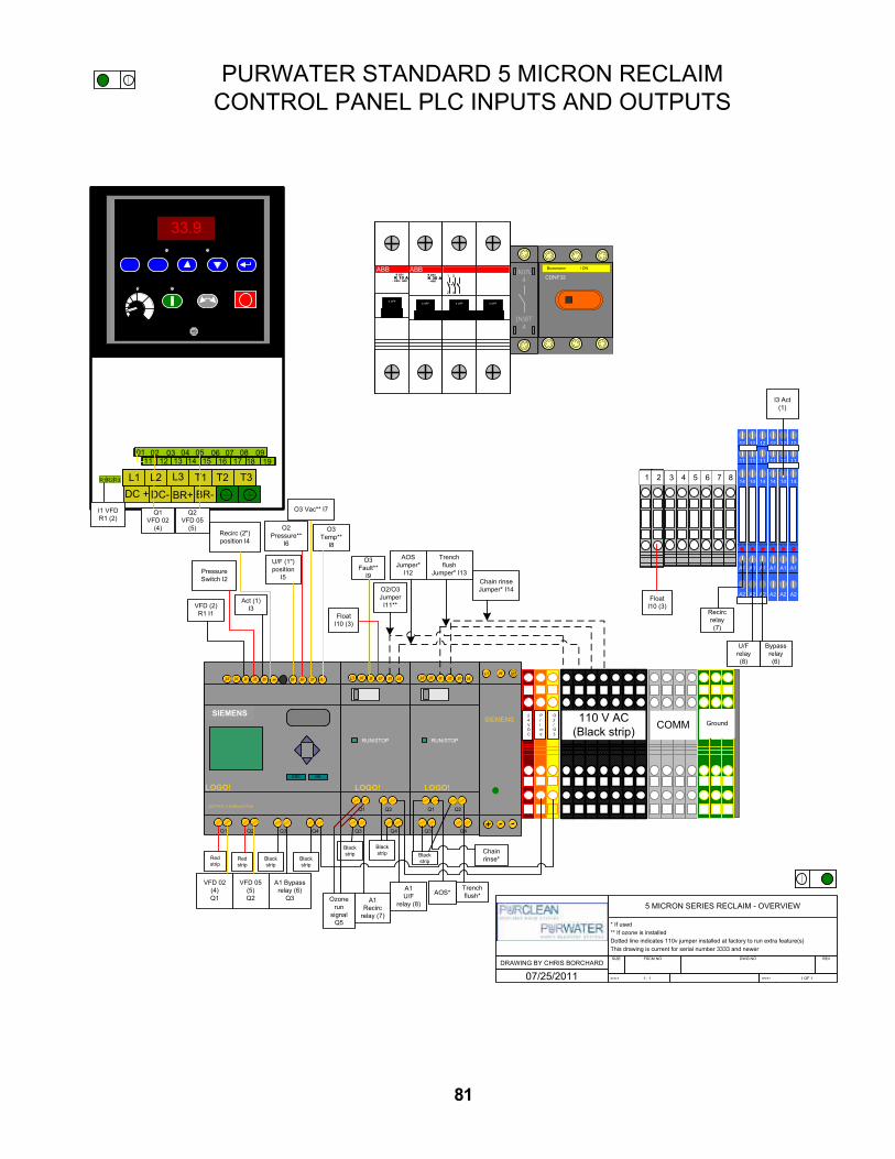
Black strip
5 MICRON SERIES RECLAIM - OVERVIEW
* If used** If ozone is installedDotted line indicates 110v jumper installed at factory to run extra feature(s)This drawing is current for serial number 3333 and newer
DRAWING BY CHRIS BORCHARD
07/25/2011
SIZE FSCM NO DWG NO REV
SCALE 1 : 1 SHEET 1 OF 1
0 OFF
ABBK 10 AS 201
- 230 / 400
0 OFF0 OFF 0 OFF
ABBS 203K 30 A- 400
3
4
1
2
Bussmann t ON
CDNF32(N)7L
4
(N)8T4
33.9
AB
DC +L1 L2 L3 T1 T2 T3
DC- BR+ BR-
01 02 03 04 05 06 07 08 0911 12 13 14 15 16 17 18 19
R1R2R3
SIEMENS
LOGO!
OUTPUT 4 X RELAY/10A
Q1 Q2 Q4
I5 I6 I7 I8I1 I2 I4I3L1 N
Q3
ESC OK
LOGO!
Q1 Q2
Q4
I1 I2 I4I3L1 N
Q3
RUN/STOP
LOGO!
Q1 Q2
Q4
I1 I2 I4I3L1 N
Q3
RUN/STOP
SIEMENS
L1 N
+ - -
24VDC
110 V AC(Black strip) COMM
Prime
O2/O3
Ground
A1
A2
14
11
12
100-125
A1
A2
14
11
12
100-125
A1
A2
14
11
12
100-125
A1
A2
14
11
12
100-125
A1
A2
14
11
12
100-125
A1
A2
14
11
12
100-125
1 2 63 4 5 6 7 8
O2 Pressure**
I6
O3 Vac** I7
O3 Temp**
I8
O3 Fault**
I9
O2/O3 Jumper
I11**
AOS Jumper*
I12
U/F (1") position
I5
Recirc (2") position I4
Act (1) I3
Pressure Switch I2
VFD (2)R1 I1
I3 Act (1)
I1 VFD R1 (2)
Trench flush
Jumper* I13Chain rinse Jumper* I14
Float I10 (3)
Float I10 (3)
VFD 02 (4)Q1
VFD 05 (5)Q2
A1 Bypass relay (6)
Q3
Black strip
Redstrip
Redstrip
Black strip
Ozone run
signal Q5
Black strip
A1Recirc
relay (7)
A1 U/F
relay (8)
Black strip
AOS*Trench flush*
Chain rinse*
Bypass relay (6)
Recirc relay (7)
U/Frelay (8)
Q1 VFD 02
(4)
Q2 VFD 05
(5)
81
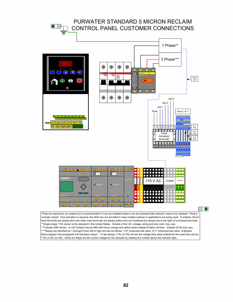
0 OFF
ABBK 10 AS 201
- 230 / 400
0 OFF0 OFF 0 OFF
ABBS 203K 30 A- 400
3
4
1
2
Bussmann t ON
CDNF32(N)7L
4
(N)8T4
33.9
AB
DC +L1 L2 L3 T1 T2 T3
DC- BR+ BR-
01 02 03 04 05 06 07 08 0911 12 13 14 15 16 17 18 19
R1R2R3
SIEMENS
LOGO!
OUTPUT 4 X RELAY/10A
Q1 Q2 Q4
I5 I6 I7 I8I1 I2 I4I3L1 N
Q3
ESC OK
LOGO!
Q1 Q2
Q4
I1 I2 I4I3L1 N
Q3
RUN/STOP
LOGO!
Q1 Q2
Q4
I1 I2 I4I3L1 N
Q3
RUN/STOP
SIEMENS
L1 N
+ - -
24VDC
110 V AC COMMPrime
O2/O3
Ground
A1
A2
14
11
12
100-125
A1
A2
14
11
12
100-125
A1
A2
14
11
12
100-125
A1
A2
14
11
12
100-125
A1
A2
14
11
12
100-125
A1
A2
14
11
12
100-125
1 2 63 4 5 6 7 8
Float
Act 1
Act 2
Act 3
Act 1 relay
Act 2 relay
Act 3 relay
3 Phase***
1 Phase**
Relays 1-6****
White wire
Float/ Activation terminals*
PURWATER STANDARD 5 MICRON RECLAIMCONTROL PANEL CUSTOMER CONNECTIONS
*Float not required to run system but is recommended if it can be installed where it can be accessed later should it need to be replaced. Float is normally closed. One activation is required, the other two are provided in case multiple washes or applications are being used. If ordered, trench flush terminals are always blue and chain rinse terminals are always yellow and not numbered but always are to the right of numbered terminals.**Single phase 110v shown is the standard in the United States. Outside of the US, voltage, wiring and wire color may vary.***3 phase 208v shown. In US 3 phase may be 480 with brown orange and yellow wires instead of black red blue. Outside of US may vary.****Relays are identified as 1 through 6 from left to right and are as follows: 1=2" motorized ball valve, 2=1" motorized ball valve, 3=Bypass (Runs bypass if de-energized) 4-6=activation relays. 1-3 are always 110v (in US) 4-6 are the voltage they were ordered for the wash and can be 110v or 24v (in US). Verify act relays are the correct voltage for the carwash by reading the number above the indicator light.
82

0 OFF
ABBK 10 AS 201
- 230 / 400
0 OFF0 OFF 0 OFF
ABBS 203K 30 A- 400
3
4
1
2
Bussmann t ON
CDNF32(N)7L
4
(N)8T4
33.9
AB
DC +L1 L2 L3 T1 T2 T3
DC- BR+ BR-
01 02 03 04 05 06 07 08 0911 12 13 14 15 16 17 18 19
R1R2R3
I1
SIEMENS
LOGO!
OUTPUT 4 X RELAY/10A
Q1 Q2 Q4
I5 I6 I7 I8I1 I2 I4I3L1 N
Q3
ESC OK
LOGO!
Q1 Q2
Q4
I1 I2 I4I3L1 N
Q3
RUN/STOP
LOGO!
Q1 Q2
Q4
I1 I2 I4I3L1 N
Q3
RUN/STOP
SIEMENS
L1 N
+ - -
24VDC
110 V AC COMMPrime
O2/O3
Ground
A1
A2
14
11
12
100-125
A1
A2
14
11
12
100-125
A1
A2
14
11
12
100-125
A1
A2
14
11
12
100-125
A1
A2
14
11
12
100-125
A1
A2
14
11
12
100-125
1 2 63 4 5 6 7 8
Float
Act 1
Act 2
Act 3
3 Phase***
1 Phase**
White wire
Float/ Activation terminals*
PURWATER 5 MICRON RECLAIM W/ CHAIN RINSECONTROL PANEL CUSTOMER CONNECTIONS
Act 1 relay
Act 2 relay
Act 3 relay
Relays 1-6****
Chain rinse solenoid
*Float not required to run system but is recommended if it can be installed where it can be accessed later should it need to be replaced. Float is normally closed. One activation is required, the other two are provided in case multiple washes or applications are being used. If ordered, trench flush terminals are always blue and chain rinse terminals are always yellow and not numbered but always are to the right of numbered terminals.**Single phase 110v shown is the standard in the United States. Outside of the US, voltage, wiring and wire color may vary.***3 phase 208v shown. In US 3 phase may be 480 with brown orange and yellow wires instead of black red blue. Outside of US may vary.****Relays are identified as 1 through 6 from left to right and are as follows: 1=2" motorized ball valve, 2=1" motorized ball valve, 3=Bypass (Runs bypass if de-energized) 4-6=activation relays. 1-3 are always 110v (in US) 4-6 are the voltage they were ordered for the wash and can be 110v or 24v (in US). Verify act relays are the correct voltage for the carwash by reading the number above the indicator light.
83
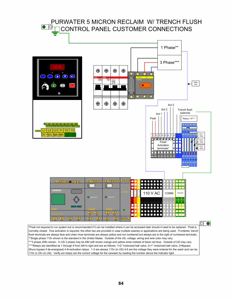
0 OFF
ABBK 10 AS 201
- 230 / 400
0 OFF0 OFF 0 OFF
ABBS 203K 30 A- 400
3
4
1
2
Bussmann t ON
CDNF32(N)7L
4
(N)8T4
33.9
AB
DC +L1 L2 L3 T1 T2 T3
DC- BR+ BR-
01 02 03 04 05 06 07 08 0911 12 13 14 15 16 17 18 19
R1R2R3
SIEMENS
LOGO!
OUTPUT 4 X RELAY/10A
Q1 Q2 Q4
I5 I6 I7 I8I1 I2 I4I3L1 N
Q3
ESC OK
LOGO!
Q1 Q2
Q4
I1 I2 I4I3L1 N
Q3
RUN/STOP
LOGO!
Q1 Q2
Q4
I1 I2 I4I3L1 N
Q3
RUN/STOP
SIEMENS
L1 N
+ - -
24VDC
110 V AC COMMPrime
O2/O3
Ground
A1
A2
14
11
12
100-125
A1
A2
14
11
12
100-125
A1
A2
14
11
12
100-125
A1
A2
14
11
12
100-125
A1
A2
14
11
12
100-125
A1
A2
14
11
12
100-125
1 2 63 4 5 6 7 8
Float
Act 1
Act 2
Act 3
3 Phase***
1 Phase**
White wire
Float/ Activation terminals*
PURWATER 5 MICRON RECLAIM W/ TRENCH FLUSH CONTROL PANEL CUSTOMER CONNECTIONS
Act 1 relay
Act 2 relay
Act 3 relay
Relays 1-6****
Trench flush solenoid
*Float not required to run system but is recommended if it can be installed where it can be accessed later should it need to be replaced. Float is normally closed. One activation is required, the other two are provided in case multiple washes or applications are being used. If ordered, trench flush terminals are always blue and chain rinse terminals are always yellow and not numbered but always are to the right of numbered terminals.**Single phase 110v shown is the standard in the United States. Outside of the US, voltage, wiring and wire color may vary.***3 phase 208v shown. In US 3 phase may be 480 with brown orange and yellow wires instead of black red blue. Outside of US may vary.****Relays are identified as 1 through 6 from left to right and are as follows: 1=2" motorized ball valve, 2=1" motorized ball valve, 3=Bypass (Runs bypass if de-energized) 4-6=activation relays. 1-3 are always 110v (in US) 4-6 are the voltage they were ordered for the wash and can be 110v or 24v (in US). Verify act relays are the correct voltage for the carwash by reading the number above the indicator light.
84

Relays removed for
drawing space only
0 OFF
ABBK 10 AS 201
- 230 / 400
0 OFF0 OFF 0 OFF
ABBS 203K 30 A- 400
3
4
1
2
Bussmann t ON
CDNF32(N)7L
4
(N)8T4
33.9
AB
DC +L1 L2 L3 T1 T2 T3
DC- BR+ BR-
01 02 03 04 05 06 07 08 0911 12 13 14 15 16 17 18 19
R1R2R3
SIEMENS
LOGO!
OUTPUT 4 X RELAY/10A
Q1 Q2 Q4
I5 I6 I7 I8I1 I2 I4I3L1 N
Q3
ESC OK
LOGO!
Q1 Q2
Q4
I1 I2 I4I3L1 N
Q3
RUN/STOP
LOGO!
Q1 Q2
Q4
I1 I2 I4I3L1 N
Q3
RUN/STOP
SIEMENS
L1 N
+ - -
24VDC
110 V AC COMMPrime
O2/O3
Ground
Float
Act 1
Act 2
Act 3
3 Phase***
1 Phase**
White wire
PURWATER 5 MICRON RECLAIM W/ TRENCH FLUSH & CHAIN RINSE CONTROL PANEL CUSTOMER
CONNECTIONS
Trench flush solenoid
*Float not required to run system but is recommended if it can be installed where it can be accessed later should it need to be replaced. Float is normally closed. One activation is required, the other two are provided in case multiple washes or applications are being used. If ordered, trench flush terminals are always blue and chain rinse terminals are always yellow and not numbered but always are to the right of numbered terminals.**Single phase 110v shown is the standard in the United States. Outside of the US, voltage, wiring and wire color may vary.***3 phase 208v shown. In US 3 phase may be 480 with brown orange and yellow wires instead of black red blue. Outside of US may vary.****Relays are removed for drawing space but are identified as 1 through 6 from left to right and are as follows: 1=2" motorized ball valve, 2=1" motorized ball valve, 3=Bypass (Runs bypass if de-energized) 4-6=activation relays. 1-3 are always 110v (in US) 4-6 are the voltage they were ordered for the wash and can be 110v or 24v (in US). Verify act relays are the correct voltage for the carwash by reading the number above the indicator light.
1 2 63 4 5 6 7 8
Float/ Activation terminals*
Chain rinse solenoid
85

StationarySeat
RotatingSeal
Spring
1419 1294
Figure 3
Service 9
REMOVAL OF OLD SEALRefer to Figure 3 for Mechanical Seal parts indentificaiton.
Step 1. Disconnect all power to pump.
Step 2. Close isolation valves to cut pump off from system.
Step 3. Drain pump; be sure to vent pump.
Step 4. Remove motor hold down bolts and bolts holding adapter/sealplate (Key No. 6, Page 11) to pump body (Key No. 20). Slidemotor, adapter/ seal plate and impeller (Key No. 12) backward toclear pump body.
Step 5. Remove impeller screw and washer from end of shaft and slideimpeller off of shaft.
Step 6. Unbolt adapter/seal plate from motor.
Step 7. Use two screwdrivers (Figure 4) or bearing puller to carefully sep-arate motor from adapter/seal plate, bringing rotating half of seal(Key No. 10) off with adapter/seal plate. Shaft sleeve (Key No. 2A)may come off with seal.
Step 8. Use hammer, if necessary, to drive shaft sleeve out of seal. Cleanup shaft sleeve with emery paper if necessary.
Step 9. Place adapter/seal plate face down on bench and drive old sta-tionary half of seal out of adapter/seal plate by carefully tapingwith screwdriver and hammer (Figure 5).
Step 10. Use a wire brush to thoroughly clean adapter/seal plate cavity. Besure all dust and grime are out of seal cavity before installing newseal.
1421 1294
Figure 5
If Gear Puller is used,place jackscrew here.Rotating Seat will come off
with adapter/sealplate.
1420 1294
Figure 4
8586

Service 10
INSTALLING NEW SEALStep 1. IMPORTANT: Seal faces are highly polished and lapped. Handle
with care. Any mar, nick or scratch on seal face will cause it toleak. BE SURE to install with polished faces toward each other.
Step 2. Clean polished surface of ceramic seat with clean cloth.
Step 3. Wet O-Ring around ceramic seat with liquid soap.
Step 4. Press stationary (ceramic) half of seal into cavity firmly and squarelywith thumb pressure. If it does not seal properly, remove and placeface up on bench. Re-clean adapter/seal plate cavity. Seal shouldnow seat correctly.
Step 5. If seal does not seat after recleaning adapter/seal plate cavity, placea cardboard washer over polished face of seal and carefully pressinto place using a piece of 1” standard pipe as a press. (Figure 6).NOTE: BE SURE you do not scratch seal face.
Step 6. Dispose of cardboard washer and recheck seal face to be sure it isfree of dirt, foreign particles, scratches and grease.
7. Inspect shaft and shaft sleeve to be sure they are clean.
8. Re-install O-Ring, shaft sleeve and slinger (Key No. 4) on shaft.NOTE: A small amount of grease or Never-Seez under shaft sleevewill help prevent shaft and sleeve from freezing together whenpump is in service.
9. Remount adapter/seal plate to motor, being careful not to scratchseal face.
Step 10. Apply liquid soap to inside diameter and outside face of rubberdrive ring on rotating half of seal.
Step 11. Slide seal assembly onto shaft sleeve (sealing face first) far enoughso that seal spring is located on shaft sleeve. NOTE: Be careful notto nick carbon seal face when passing it over end of shaft sleeve.
Step 12. Slide impeller and gaskets (Key Nos. 12 and 11) onto shaft withkey (Key No. 3) in position. Be sure to maintain proper order asshown in Exploded View, Page 11.
Step 13. Install washer, gaskets, and impeller screw (Key Nos. 14, 15, 16,17) on end of shaft and tighten screw until it is snug. This shouldlocate seal in place and bring seal faces together.
Step 14. Re-install motor, adapter and impeller assembly on volute, usingnew gasket (Key No. 7).
Step 15. Re-install motor hold-down bolts.
Step 16. Check all bolts for tightness.
Step 17. Pumps below water level: Close drains; open isolation valves tofill pump. Pumps above water level: Prime pump. Open isolationvalves if they were closed at disassembly.
Step 18. When pump is full, close air vents.
Step 19. Reconnect power to pump and system is ready for operation.
1" Standard Pipe
Stationary Seat
CardboardWasher
(Supplied with seal)
1422 1294
Figure 6
8687

24
MAINTENANCE
Disassembly – Motor Drive
Mechanical Seal Replacement
1135 0794
1137 0794
• Unfasten hardware holding volute to bracket.NOTE: For model B4EY, consult factory for specialinstructions.
• Remove volute case to expose impeller.
• Peel off old gasket or O-Ring and discard.
• Hold impeller stationary and remove impellerscrew and associated hardware.
• Remove capscrews holding bracket to motor.
• Install a standard gear puller to shaft end andmotor bracket placing puller fingers in the areashown.
• Rotate gear puller jackscrew until impeller clears
shaft. Mechanical shaft seal will come off withmotor bracket.
• If a seal retaining ring is part of the assembly, itwill need to be replaced.
Gear PullerFinger
Gear PullerFinger
Gear PullerJackscrew
Note:A hexnut placed between thejackscrew and shaft end willprevent damage to the shaftand impeller screw threads.
1138 0794
Key
ShaftSleeve
1139 0794
Procedure and parts willvary slightly depending
on pump style.
5
43
21
StationarySeat
1140 0794
StationarySeat
RotatingSeat
Spring
SpringRetainer
0794
• Push stationary seat out ofseal cavity from the backof bracket.
• Clean seal cavity in bracket thoroughly.
Typical Mechanical Seal
88

MAINTENANCE
25
Reassembly – Motor Drive
Mechanical Seal Replacement
• Place bracket on a smooth, flat surface, pump side up.
• Apply a small amount of mineral oil to O-Ring onstationary seat and press into seal cavity. Coverceramic face with cardboard washer and press
straight in using a piece of pipe or tubing.
• Reinstall bracket on motor using extreme care not toscratch or chip ceramic face of seal with shaft.
• Apply a small amount of mineral oil to inside dia-meter of rubber ring in rotating seat and outside ofshaft sleeve. Slide rotating seat onto shaft, pol-ished face first, until it is tight against ceramic face.
• Compress seal spring, and install retaining ring (ifused) in shaft sleeve groove.
• Place impeller key in motor shaft keyway. Slideimpeller on to shaft as far as possible.
• Apply non-permanent thread adhesive to impellercapscrew and shaft threads.
• Install impeller washer, shakeproof lockwasher,and capscrew.
Procedure and parts willvary slightly depending
on pump style.
4
1
Polished FaceCardboard washer(Supplied with seal)
1142 0794
If shaft is threaded, cover threadswith tape to protect seal duringinstallation.
1143 0794
2
Truarc
1144 0794
1145 0794
Key
3
1146 0794
5• Install new gasket or O-Ring and volute case onto
bracket.
• Install new O-Ring gasket and volute case on tobracket.
• Apply anti-seizing compound to capscrews andtighten securely.
Use Snap Ring Pliers to
Remove
89

90
Theory of Operation/Product Description
PurWater 4 & 8 Gram Ozone Manual
4 Gram Ozone System (CD12/AD)
8 Gram Ozone System (2- CD12/AD units)
The feed gas (Oxygen) is drawn through the ozone generator by the vacuum created at the ozone injector rather than by the pressure from the air preparation system compressors. As the feed gas enters the thermally-protected reaction chambers inside the ozone generator, some of the oxygen molecules are split while passing through the high voltage electrical field (the “corona”), forming single oxygen atoms (O1). These oxygen atoms then recombine with other oxygen molecules in the air stream, forming ozone.
The Ozone Generators are designed to produce Ozone for 30 minutes after first being powered up and then requires a 30 minute cool down period. This cycle is controlled by the Reclaim System’s PLC and the status of whether the Ozone is “On or Off” can be read on the display of the HMI screen, located on the Reclaim’s Main Control Box.
Many safety features are also built in, including main power fuses, thermal protection, cover safety switch, and back flow prevention.

91
Ozone Generator LED DisplayFigure 11
isot
LED Function CD10 CD10/AD CD12 CD12/ADOZONE The ten LEDs represent 0-100%, MAX MAX MAX MAX
OUTPUT minimum to maximum ozone output.Each LED i s e q u a l t o 1 0 % o u t p u t .These LEDs can be adjusted with themanual output control knob located atthe bottom of the ozone generator orautomatically w i t h a remote 4-20mA
OZONE OZONE OZONE OZONEOUTPUT OUTPUT OUTPUT OUTPUT
control signal.
POWER Main Power is “ON” to the ozonegenerator, when LED is illuminated.
HVDRIVE
EXTLOOP
Power is being sent to the high voltagedrive board, when the LED isilluminated.
MIN MIN MIN MIN
The External Loop has continuitythrough it when the LED is n
POWER
HV DRIVE
POWER
HV DRIVE
POWER
HV DRIVE 1
POWER
HV DRIVE 1
ot EXT LOOP EXT LOOP EXT LOOP HI TEMP 1illuminated, which indicates ozone is
being p r o d u c e d . The E x t e r n a l L o o p does n o t h a v e c o n t i n u i t y , w h e n t h e LED is illuminated, which indicates no ozone production.
HI TEMP HI TEMP
AIR PREP
DRYER 1
HI TEMP 1 HV DRIVE 2 HV DRIVE 2 HI TEMP 2
EXT LOOP
HI TEMP 2
EXT LOOP
AIR PREP
DRYER 1
DRYER 2
HIGH The High Temp LED will not beTEMP illuminated during normal operation. If
the ozone generator’s internaltemperature is in excess of 150˚F the
DRYER 2
High Temp LED will illuminate,which will also discontinue ozone production.
AIR CD10/AD and CD12/AD Only: ThePREP Dryer Timer LED will flash
continuously during normal operationand indicates that the dryer timer cycleis operating correctly.
DRYER 1 CD10/AD and CD12/AD Only:
DRYER 1 LED will be illuminated when dryer chamber #1 is heating.
DRYER 2 CD10/AD and CD12/AD Only:DRYER 2 LED will be illuminated when dryer chamber #2 is heating.
Note: There is a 30 minute period where Dryer #1 and Dryer #2 are off. This is normal. The dryers are ina cool down phase before switching.
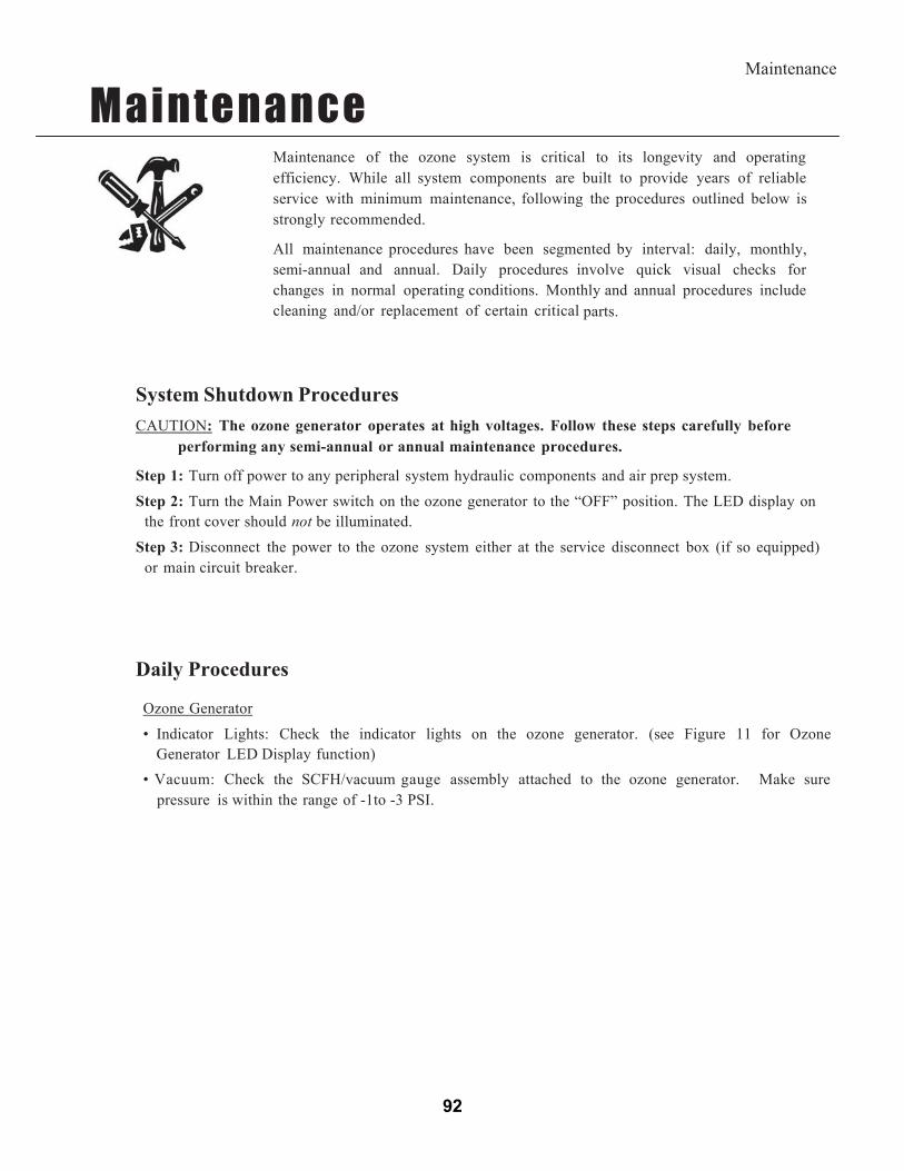
92
Maintenance
M a i n t e n a n c e
Maintenance of the ozone system is critical to its longevity and operating efficiency. While all system components are built to provide years of reliable service with minimum maintenance, following the procedures outlined below is strongly recommended.
All maintenance procedures have been segmented by interval: daily, monthly, semi-annual and annual. Daily procedures involve quick visual checks for changes in normal operating conditions. Monthly and annual procedures include cleaning and/or replacement of certain critical parts.
System Shutdown Procedures
CAUTION: The ozone generator operates at high voltages. Follow these steps carefully before performing any semi-annual or annual maintenance procedures.
Step 1: Turn off power to any peripheral system hydraulic components and air prep system.
Step 2: Turn the Main Power switch on the ozone generator to the “OFF” position. The LED display on the front cover should not be illuminated.
Step 3: Disconnect the power to the ozone system either at the service disconnect box (if so equipped) or main circuit breaker.
Daily Procedures
Ozone Generator
• Indicator Lights: Check the indicator lights on the ozone generator. (see Figure 11 for Ozone Generator LED Display function)
• Vacuum: Check the SCFH/vacuum gauge assembly attached to the ozone generator. Make sure pressure is within the range of -1to -3 PSI.
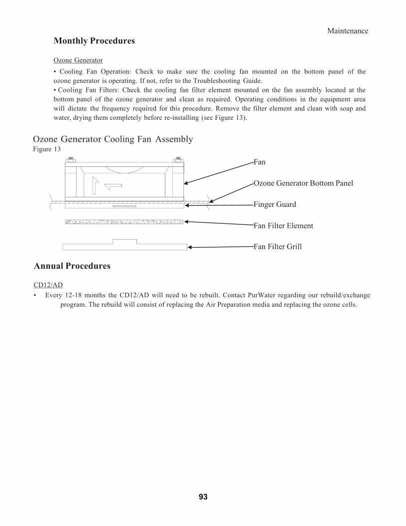
93
Maintenance
Monthly Procedures
Ozone Generator• Cooling Fan Operation: Check to make sure the cooling fan mounted on the bottom panel of the ozone generator is operating. If not, refer to the Troubleshooting Guide.• Cooling Fan Filters: Check the cooling fan filter element mounted on the fan assembly located at the bottom panel of the ozone generator and clean as required. Operating conditions in the equipment area will dictate the frequency required for this procedure. Remove the filter element and clean with soap and water, drying them completely before re-installing (see Figure 13).
Ozone Generator Cooling Fan AssemblyFigure 13
Fan
Ozone Generator Bottom Panel
Finger Guard
Fan Filter Element
Fan Filter Grill
Annual Procedures
CD12/AD• Every 12-18 months the CD12/AD will need to be rebuilt. Contact PurWater regarding our rebuild/exchange
program. The rebuild will consist of replacing the Air Preparation media and replacing the ozone cells.

94
TroubleshootingOzone Generator
Air Preparation – Heat Regenerative Dry Air
Problem/Symptom Possible Cause SolutionAir Prep LED not flashing -Air dryer board not functioning -Replace air dryer boardDryer 1 or 2 LED not illuminated
-Air dryer board not functioning-Dryer 1 LED will not illuminate whenDryer 2 LED is illuminated
-Dryer 1 is in cool down mode-Dryer 2 LED will not illuminate whenDryer 1 LED is illuminated
-Dryer 2 LED is in cool down mode
-Replace air dryer board-See “Theory of Operation and ProductDescription - Air Preparation System”
-See “Ozone Generator LED Display, Figure11”
Dryer chamber(s) notheating
-Heating element not functioning -Replace Heating element
Indicating desiccantcartridge has changed from blue & white to all pink or white. Moisture has enteredair prep system.
-Unit does not have constant power
-Excessive duty cycle
-Excessive relative humidity-Solenoid valve not operating-Air dryer board not functioning
-Unit must have constant power
-Duty cycle must not exceed 10 hours in a 24hour period
-Relative humidity must not exceed 75%-Replace solenoid valve-Replace air dryer board
Ozone Generator Problem/Symptom Possible Cause SolutionLow vacuum -Hydraulics/Pneumatics out of adjustment
-Defective check valve(s)-Loose internal fittings-Defective dielectrics
-See “Reclaim Manual – Low Vacuum Fault”-Replace check valves -Check all fittings, tighten as required-Check & replace as required
Unit flooded with water -Defective check valve(s)
-Assess damage, repair as required, replace check valve(s)
Ozone smell detected from or near ozone generator
-Insufficient vacuum at venturi
-Loose internal fittings-Defective O-ring seals in reaction chamber(s)
- See “Reclaim Manual – Low Vacuum Fault”
-Check all fittings, tighten as required-Check & replace as required

95
Troubleshooting
Ozone Generator
Problem/Symptom Possible Cause SolutionLED display is notilluminated
-No power to unit-Main power switch is in the “OFF”position
-Blown fuse(s)-Incorrect wiring
-LED display board ribbon cable isdisconnected from output control board
-Check circuit breakers-Turn switch to the “ON” positioning
-Replace fuse(s)-See PurWater Reclaim Control Panel W/ 4 Gram Ozone System Diagram & Logic Schematic-Connect ribbon cable (be sure all of the pins
l i t d i t th t t t l‘Main Power’ LED is not illuminated, but all otherLED’s are illuminated
-LED display board is inoperable -Replace LED display board
Circuit breaker trips -Incorrect wiring
-Circuit breaker amperage does not match draw
-Unit flooded with water
-See PurWater Reclaim Control Panel W/ 4 Gram Ozone System Diagram & Logic Schematic-Replace with correct circuit breaker
-Assess damage, correct cause and rebuild asrequired
‘HV Drive’ LED is not illuminated
-No power to the high voltage drive board -Check board to be sure it is attached securelyto the mother board
-Bad high voltage drive board, replace asrequired
‘External Loop’ LED is illuminated
-The external loop does not have continuity
-System is in a 30 minute cool down period
-Check HMI Screen on Reclaim Control Panel for fault status - Check HMI Screen on Reclaim Control Panel “Ozone On or Ozone Off” status
‘Ozone Output’ LED’s arenot illuminated
-The manual 0-100% output potentiometer is set to 0% output
-Adjust potentiometer clock wise to desired set point
‘Hi Temp’ LED illuminated -Unit is overheating -Check fan for proper operation and clean fanfilter
-Check operating temperature
Internal Mother Board‘Power’ LED not illuminated
-No power to mother board-Inoperable mother board-Blown mother board fuse
-See “Installation Procedures – Electrical”-Replacement Mother Board-Replace fuse
Receive an electrical shock upon touching the unit
-Incorrect wiring
-Unit not grounded-Unit flooded with water
-See PurWater Reclaim Control Panel W/ 4 Gram Ozone System Diagram & Logic Schematic-Ground unit according to local codes-Assess damage, correct cause and rebuild asrequired
Fan not operating -Debris caught in fan-Fan inoperable
-Remove debris-Replace fan
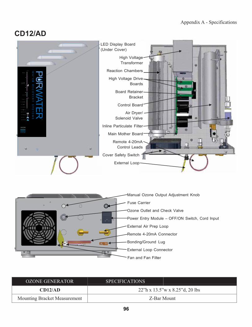
96-44
Appendix A - Specifications
CD12/AD
LED Display Board(Under Cover)
High VoltageTransformer
Reaction Chambers
High Voltage Drive
Boards
Board RetainerBracket
Control Board
Air Dryer/
Solenoid Valve
Inline Particulate Filter
Main Mother Board
Remote 4-20mA Control Leads
Cover Safety Switch
External Loop
Manual Ozone Output Adjustment Knob
Fuse Carrier
Ozone Outlet and Check Valve
Power Entry Module – OFF/ON Switch, Cord Input
External Air Prep Loop
Remote 4-20mA Connector
Bonding/Ground Lug
External Loop Connector
Fan and Fan Filter
OZONE GENERATOR SPECIFICATIONS
CD12/AD 22”h x 13.5”w x 8.25”d, 20 lbs
Mounting Bracket Measurement Z-Bar Mount

97
Black strip
5 MICRON SERIES RECLAIM – W/ 4 GRAM OZONE
* If used** If ozone is installedDotted line indicates 110v jumper installed at factory to run extra feature(s)This drawing is current for serial number 3333 and newer
DRAWING BY RICH CARPENTER
5/28/14
SIZE FSCM NO DWG NO REV
SCALE 1 : 1 SHEET 1 OF 1
PURWATER RECLAIMCONTROL PANEL
W/ 4 GRAM OZONE SYSTEM
0 OFF
ABBK 10 AS 201
- 230 / 400
0 OFF0 OFF 0 OFF
ABBS 203K 30 A- 400
3
4
1
2
Bussmann t ON
CDNF32(N)7L
4
(N)8T4
33.9
AB
DC +L1 L2 L3 T1 T2 T3
DC- BR+ BR-
01 02 03 04 05 06 07 08 0911 12 13 14 15 16 17 18 19
R1R2R3
SIEMENS
LOGO!
OUTPUT 4 X RELAY/10A
Q1 Q2 Q4
I5 I6 I7 I8I1 I2 I4I3L1 N
Q3
ESC OK
LOGO!
Q1 Q2
Q4
I1 I2 I4I3L1 N
Q3
RUN/STOP
LOGO!
Q1 Q2
Q4
I1 I2 I4I3L1 N
Q3
RUN/STOP
SIEMENS
L1 N
+ - -
24VDC
110 V AC(Black strip) COMM
Prime
O2/O3
Ground
A1
A2
14
11
12
100-125
A1
A2
14
11
12
100-125
A1
A2
14
11
12
100-125
A1
A2
14
11
12
100-125
A1
A2
14
11
12
100-125
A1
A2
14
11
12
100-125
1 2 63 4 5 6 7 8
O3 Vac** I7
O2/O3 Jumper
I11**
AOSJumper*
I12
U/F (1") position
I5
Recirc (2") position I4
Act (1) I3
Pressure Switch I2
VFD (2)R1 I1
I3 Act (1)
I1 VFD R1 (2)
Trench flush
Jumper* I13Chain rinse Jumper* I14
Float I10 (3)
Float I10 (3)
VFD 02 (4)Q1
VFD 05 (5)Q2
A1 Bypass relay (6)
Q3
Black strip
Red strip
Red strip
Black strip
Ozone run
signal Q5
Black strip
A1 Recirc
relay (7)
A1 U/F
relay (8)
Black strip
AOS*Trench flush*
Chain rinse*
Bypass relay (6)
Recirc relay (7)
U/Frelay (8)
Q1VFD 02
(4)
Q2VFD 05
(5)
Jumper from Input 4 to terminal 12 on Recirc relay if system is PW100 (No Recirc Ball Valve)
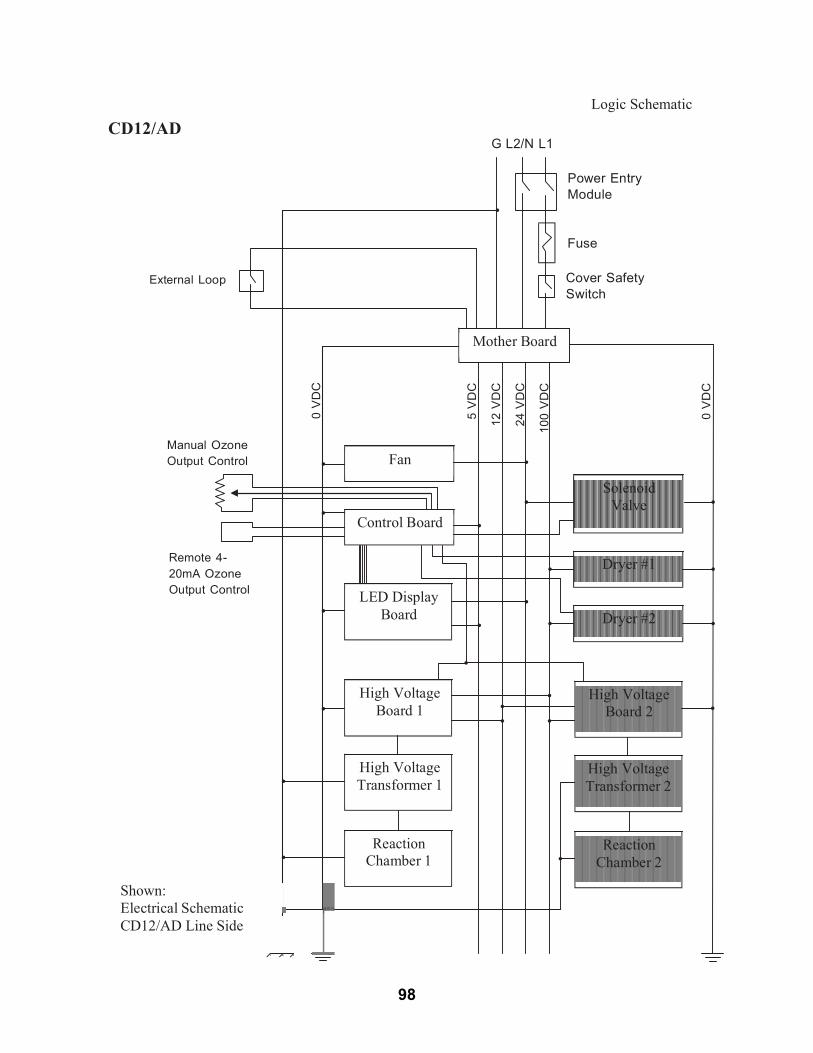
98
0V
DC
5V
DC
12
VD
C
24 V
DC
100
VD
C
0V
DC
CD12/AD
G L2/N L1
Logic Schematic
Power EntryModule
Fuse
External Loop Cover SafetySwitch
Mother Board
Manual OzoneOutput Control
Remote 4-20mA OzoneOutput Control
Fan
Control Board
LED Display
Board
Solenoid
Valve Dryer #1 Dryer #2
High VoltageBoard 1
High VoltageBoard 2
High VoltageTransformer 1
High VoltageTransformer 2
Shown:Electrical SchematicCD12/AD Line Side
ReactionChamber 1
ReactionChamber 2

WARRANTY
NEW WAVE INDUSTRIES, LTD. LIMITED WARRANTY
NEW WAVE INDUSTRIES, LTD. warrants to the original purchaser only, that all PUR-WATER RECLAIM SYSTEMS will be free of defects in materials and/or workmanship for a period of (1) one year from the date of delivery to the original customer, provided the enclosed instructions for operation, maintenance and care have been strictly complied with and the validation page has been sent to and received by NEW WAVE INDUSTRIES, LTD. This warranty is expressly limited to the repair or replacement of the defective component. Excluded from warranty are gauges, strainer baskets, and pump seals. This warranty does not extend to damages to person(s) or property or liabilities incidental, consequential or contingent. Purchaser shall notify NEW WAVE INDUSTRIES, LTD. in writing or by telephone should any defect appear or should any damage occur to the unit(s) for notification of valid warranty claim. NEW WAVE INDUSTRIES, LTD. will issue a Returned Goods Authorization (RGA) number for defective parts (see RGA Policy and Procedure Insert).
99
RETURN GOODS POLICY
NEW WAVE INDUSTRIES, LTD. RGA POLICY AND PROCEDUREPOLICY
All returns must be authorized by NEW WAVE INDUSTRIES, LTD. (Service Department) with a Returned Goods Authorization (RGA) form prior to return.
All returned goods must be received by NEW WAVE INDUSTRIES, LTD. within 30 days or you will not receive credit. All goods not received within 30 days will not receive credit.
Credit is contingent upon a credit evaluation inspection. 6Customer must prepay freight. PROCEDURE
Contact New Wave’s Service Department and give original invoice number and date of order to request an RGA.
New Wave’s Service Department will issue an RGA form and send it via fax or mail.
Include the RGA form inside the package and clearly write the RGA number on the outside of the package.
Customer must prepay freight. When returned parts are received by NEW WAVE INDUSTRIES, LTD., credit for
the parts is contingent upon credit evaluation inspection and warranty terms. If the customer wants to place an order for the part(s) during the return process,
then the customer is agreeing to purchase the replacement part(s) and pay the invoice when received. If the returned part(s) is found to be a warranty item NEW WAVE INDUSTRIES, LTD. will issue a credit redeemable in parts.
If New Wave Industries, LTD. sends a part that was not ordered by the customer, the customer needs to get an RGA number from NEW WAVE INDUSTRIES, LTD.
Include the RGA number clearly on the outside of the box and the part(s) to be returned.
NEW WAVE INDUSTRIES, LTD. will issue a call tag to the customer for pickup of the wrong part(s) and ship it back to New Wave’s factory, at New Wave’s expense.
NEW WAVE INDUSTRIES, LTD. will pay standard ground freight for warranty replacement parts. If the distributor/customer requires overnight/second day air delivery, shipping will be at customer’s expense.
100
START-UP WARRANTY VALIDATION
SITE: DATE:
COMPANY NAME:
MODEL # SERIAL #
MODEL # SERIAL #
MODEL # SERIAL #
ADDITIONAL INFORMATION
SOLD TO:
ADDRESS:
CITY: STATE: ZIP:
PHONE: CONTACT:
COMPLETE AND RETURN FOR WARRANTY CONSIDERATION
PLEASE RETURN VIA FAX TO: (916) 978-9995
101


