www.americanautowire.com 856-933-0801 510317 STOP WARNING: This harness is intended to be used in a modified vehicle. Please read this sheet thoroughly and be sure that you understand everything explained on it prior to opening any of the enclosed packages, or before attempting to install any of the components. Once this kit has been opened or a component installed, the kit is not returnable. Some early Broncos had rectangular holes in the firewall behind the engine and a small round hole in the upper driver side of the firewall. For your new AAW kit, you will need to open up the driver’s side hole to 1 1/2” and you will need to make a new 1 1/2” hole on the passenger side as well. The center rectangular hole will not be used at all and should be closed up in some way. New grommets to line these two new 1 1/2” holes have been pro- vided for you in the 510323 grommet and parts kit. 1. This kit should be used in a MODIFIED application only. You will need to purchase a new plastic glovebox liner assembly without the factory fusebox hole cut into it (these are available from various sources) as the new AAW fusepanel harness mounts inside the left hand side of the glovebox area where the factory dash speaker was originally located. You cannot use a stock radio speaker when using this kit. 2. This kit only supports the use of a higher current self-exciting 1 wire, or other style internally regulated alternator. An adapter may be necessary for certain applications. The use of a stock, low amperage alternator is seriously discouraged as they cannot handle the higher current requirements of updated ignition systems, electric fans, aftermarket A/C systems, stereo systems, air ride suspensions, and other power hungry accessories and will ultimately create performance issues with the system. 3. This kit WILL NOT support the use of a factory ammeter. All AAW kits are engineered to supply the optimum charge to the battery. To achieve this performance, we route our 8ga. charge wire directly from the alternator output terminal to the starter solenoid. Due to the path of the charge being altered from the stock configuration, the gauge can no longer see a charge vs. a discharge, so it will not work properly. When ammeters were originally used, most generator or alternator current outputs were rated at maximum of about 25-60 amps. Modified vehicles being built today typically utilize a 100 amp or higher output alternator. With these higher current units, ammeters, generally speak- ing, become a safety hazard. Ammeters are usually wired in parallel to the charging circuit, are typically unfused, and can short very easily causing a fire. A voltmeter is recommended as a good alternative. 4. This kit IS NOT set up with a resistance wire or a ballast resistor for a standard, points type ignition system. It is wired with a full 12 volt primary ignition feed that is hot in both the start and run positions. It will support HEI, MSD, other electronic ignition systems, as well as computerized Fuel Injection systems. If you wish to run a points type system, there are illustrations on the engine connection pages to do so. Extra parts that are not included in this kit will be required to complete that operation. page 1 92970070 instruction sheet Rev 1.0 8/30/2012
Transcript
www.americanautowire.com 856-933-0801
510317
STOP
WARNING: This harness is intended to be used in a modified vehicle. Please read this sheet thoroughly and be sure that you understand everything explained on it prior to opening any of the enclosed packages, or before attempting to install any of the components. Once this kit has been opened or a component installed, the kit is not returnable. Some early Broncos had rectangular holes in the firewall behind the engine and a small round hole in the upper driver side of the firewall. For your new AAW kit, you will need to open up the driver’s side hole to 1 1/2” and you will need to make a new 1 1/2” hole on the passenger side as well. The center rectangular hole will not be used at all and should be closed up in some way. New grommets to line these two new 1 1/2” holes have been pro-vided for you in the 510323 grommet and parts kit.
1. This kit should be used in a MODIFIED application only. You will need to purchase a new plastic glovebox liner assembly without the factory fusebox hole cut into it (these are available from various sources) as the new AAW fusepanel harness mounts inside the left hand side of the glovebox area where the factory dash speaker was originally located. You cannot use a stock radio speaker when using this kit.
2. This kit only supports the use of a higher current self-exciting 1 wire, or other style internally regulated alternator. An adapter may be necessary for certain applications. The use of a stock, low amperage alternator is seriously discouraged as they cannot handle the higher current requirements of updated ignition systems, electric fans, aftermarket A/C systems, stereo systems, air ride suspensions, and other power hungry accessories and will ultimately create performance issues with the system.
3. This kit WILL NOT support the use of a factory ammeter. All AAW kits are engineered to supply the optimum charge to the battery. To achieve this performance, we route our 8ga. charge wire directly from the alternator output terminal to the starter solenoid. Due to the path of the charge being altered from the stock configuration, the gauge can no longer see a charge vs. a discharge, so it will not work properly. When ammeters were originally used, most generator or alternator current outputs were rated at maximum of about 25-60 amps. Modified vehicles being built today typically utilize a 100 amp or higher output alternator. With these higher current units, ammeters, generally speak-ing, become a safety hazard. Ammeters are usually wired in parallel to the charging circuit, are typically unfused, and can short very easily causing a fire. A voltmeter is recommended as a good alternative.
4. This kit IS NOT set up with a resistance wire or a ballast resistor for a standard, points type ignition system. It is wired with a full 12 volt primary ignition feed that is hot in both the start and run positions. It will support HEI, MSD, other electronic ignition systems, as well as computerized Fuel Injection systems. If you wish to run a points type system, there are illustrations on the engine connection pages to do so. Extra parts that are not included in this kit will be required to complete that operation.
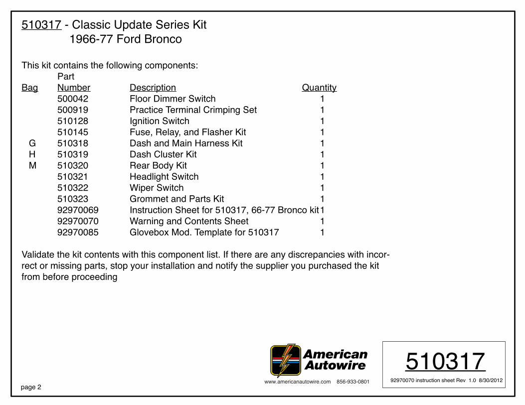
510317 - Classic Update Series Kit 1966-77 Ford Bronco
This kit contains the following components: Part Bag Number Description Quantity 500042 Floor Dimmer Switch 1 500919 Practice Terminal Crimping Set 1 510128 Ignition Switch 1 510145 Fuse, Relay, and Flasher Kit 1 G 510318 Dash and Main Harness Kit 1 H 510319 Dash Cluster Kit 1 M 510320 Rear Body Kit 1 510321 Headlight Switch 1 510322 Wiper Switch 1 510323 Grommet and Parts Kit 1 92970069 Instruction Sheet for 510317, 66-77 Bronco kit 1 92970070 Warning and Contents Sheet 1 92970085 Glovebox Mod. Template for 510317 1 Validate the kit contents with this component list. If there are any discrepancies with incor-rect or missing parts, stop your installation and notify the supplier you purchased the kit from before proceeding
Connect the Dimmer Switch wires as shown above.1. The top center terminal of the Dimmer Switch is connected to the Headlight switch.2. The terminal on the right side is connected to your headlight high beam terminal.3. The terminal on the left side is connected to your headlight low beam terminal.
150 Heller Pl #17 W Bellmawr, NJ 08031 856-933-0801
GM COLUMN MOUNTDASH MOUNTUNIVERSAL
PART #
DESCRIPTION:DIMMER SWITCH
50004292964573 instruction sheet Rev 3.0 6/29/99
Connect the Dimmer Switch wires as shown above.1. The top center terminal of the Dimmer Switch is connected to the Headlight switch.2. The terminal on the right side is connected to your headlight high beam terminal.3. The terminal on the left side is connected to your headlight low beam terminal.
Connect to your headlight high beamConnect to your headlight switchConnect to your headlight low beam
150 Heller Pl #17 W Bellmawr, NJ 08031 856-933-0801
Connect to your headlight high beamConnect to your headlight switchConnect to your headlight low beam
We Make Wiring Easy!!
another wiring product by...
We Make Wiring Easy!!
another wiring product by...
GM COLUMN MOUNTDASH MOUNTUNIVERSAL
PART #
DESCRIPTION:Ignition Switch 1964-66
Mustang &1966-77 BroncoClassic Update Series
510128
92969235 instruction sheet rev 1.0 6/12/2012
150 Heller Pl #17 W Bellmawr, NJ 08031 856-933-0801150 Heller Pl #17 W Bellmawr, NJ 08031 856-933-0801
SolenoidSolenoid
IgnitionIgnition
BatteryBattery
AccessoryAccessory
GM COLUMN MOUNTDASH MOUNTUNIVERSAL
PART #
DESCRIPTION:Ignition Switch 1964-66
Mustang &1966-77 BroncoClassic Update Series
510128
92969235 instruction sheet rev 1.0 6/12/2012
Bulb check (used only in the 66 - 77
Bronco kit. Plug the connector containing wires 33 & 33B onto this blade assembly)
Bulb check (used only in the 66 - 77
Bronco kit. Plug the connector containing wires 33 & 33B onto this blade assembly)
Page 1
STEP 1: DISCONNECT YOUR BATTERY:Disconnect the battery before installing the wiring kit to prevent any accidental shorting caused by loose bare wire ends.
STEP 2: START INSTALLING KIT: This kit is broken down into individual steps that are identified by a letter printed on the instruction sheets visible through each bag. These letters are the order of operation for installaing your kit. Start with bag letter G, then H, etc. The order ofinstallation is shown below. Use this main instruction sheet, 92970069, to complete the installation process.
STEP 3: RECONNECT YOUR BATTERY:When you have completed the installation and are ready to reconnect the battery, make sure that the following electrical system grounds are in place:
A. Battery is grounded to the ENGINE BLOCK.B. Battery is grounded to the frame.C. Engine block is grounded to the frame.D. Body is grounded to the frame.
STEP 4: CHECK ALL ELECTRICAL FUNCTIONS:Any non-functioning items should be checked for proper installation. Any problems with your wiring and electrical circuit functions should be addressed to American Autowire Systems, Inc. as soon as possible to avoid any warranty problems.
If you have any questions concerning this or any of our products, please feel free to call us at 1-856-933-0801.
AMERICAN AUTOWIRE MAKES IT EASY !!
Classic Update Series1966 - 1977 Ford Bronco
We carry many accessories for your 1966-77 Ford Bronco
INSTALLATION INSTRUCTIONS
end view of terminal proper crimp of terminal
wire core
510317
Classic Update Series
START HERE !PLEASE READ THIS BEFORE STARTING INSTALLATION !
AS THIS HARNESS IS DESIGNED FOR USE IN A MODIFIED TRUCK REQUIRING A HIGHER RATE OF CHARGE, IT DOES NOT SUPPORT THE USE OF A STOCK (ORIGINAL) ALTERATOR OR GENERATOR. IT IS DESIGNED FOR USE WITH AN INTERNALLY REGULATED GM “SI” STYLE OR SINGLE WIRE STYLE ALTERNATOR. ADAPTERS (WHICH ARE NOT INCLUDED WITH THIS KIT) THAT ARE AVAILABLE FROM SEVERAL SOURCES WILL BE NECESSARY TO USE ANY ALTERNATOR OTHER THAN A 1 WIRE UNIT.
www.americanautowire.com 856-933-0801
This wiring kit is designed for ease of installation. Please read the guidelines below, BEFORE STARTING your installation to guarantee a successful job. Use an appropriate crimping tool which folds the wings of the open barrell terminals down into the wire as shown below. ALL TERMINALS THAT YOU INSTALL SHOULD BE PROPERLY SOLDERED. Our factory crimped terminations are installed by GM approved five ton presses, and soldering these terminations is not necessary. AAW offers a great terminal crimping video entitled “Proper Crimping Video”. It can be viewed by visting YouTube. Type the following address into your web browser to go directly to the video: www.youtube.com/watch?v=8u_EkMsioMy.
1966-1977 Ford Bronco
Page 2
PART #
DESCRIPTION:
1966-77 Ford BroncoClassic Update Series Kit
510317
92970069 instruction sheet rev. 0.0 6/4/2012
Main Power Fusible Link Assembly
Alternator Power Wire and Fusible Link Assembly
Courtesy Light Extensions(extensions use (2) #631 bulbs not included in this kit)
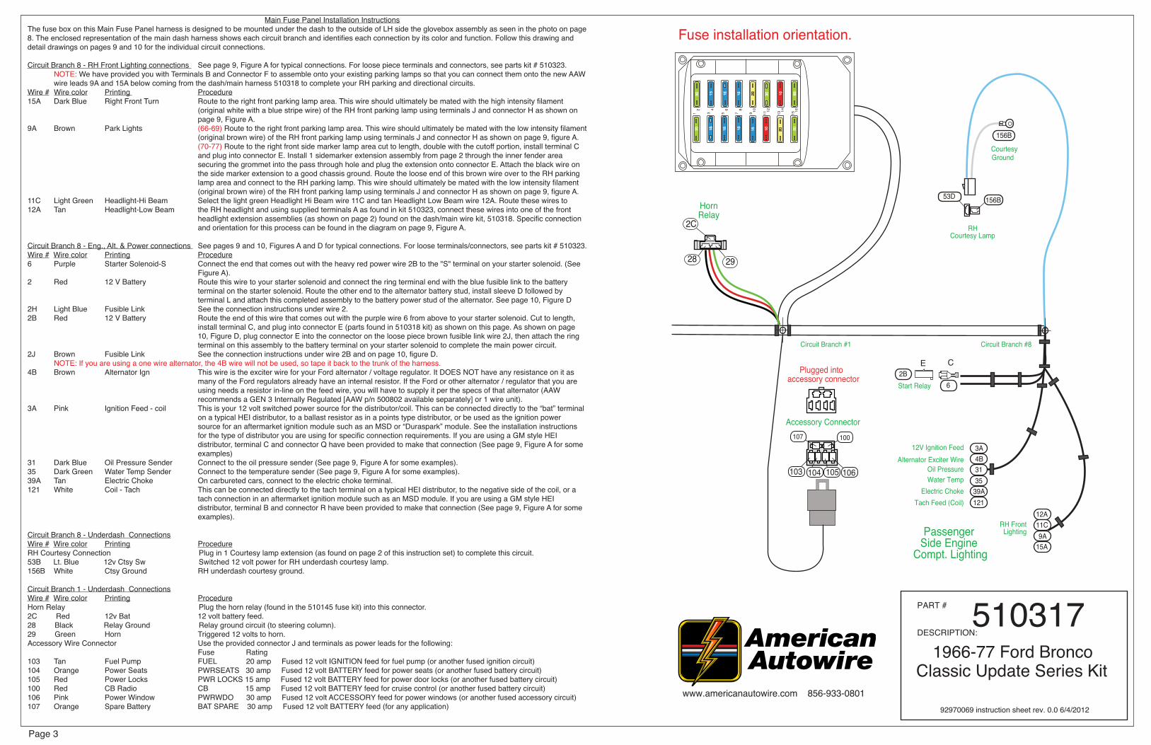
Main Fuse Panel Installation InstructionsThe fuse box on this Main Fuse Panel harness is designed to be mounted under the dash to the outside of LH side the glovebox assembly as seen in the photo on page 8. The enclosed representation of the main dash harness shows each circuit branch and identifies each connection by its color and function. Follow this drawing and detail drawings on pages 9 and 10 for the individual circuit connections.
Circuit Branch 8 - RH Front Lighting connections See page 9, Figure A for typical connections. For loose piece terminals and connectors, see parts kit # 510323. NOTE: We have provided you with Terminals B and Connector F to assemble onto your existing parking lamps so that you can connect them onto the new AAW wire leads 9A and 15A below coming from the dash/main harness 510318 to complete your RH parking and directional circuits.Wire # Wire color Printing Procedure15A Dark Blue Right Front Turn Route to the right front parking lamp area. This wire should ultimately be mated with the high intensity filament (original white with a blue stripe wire) of the RH front parking lamp using terminals J and connector H as shown on page 9, Figure A.9A Brown Park Lights (66-69) Route to the right front parking lamp area. This wire should ultimately be mated with the low intensity filament (original brown wire) of the RH front parking lamp using terminals J and connector H as shown on page 9, figure A. (70-77) Route to the right front side marker lamp area cut to length, double with the cutoff portion, install terminal C and plug into connector E. Install 1 sidemarker extension assembly from page 2 through the inner fender area securing the grommet into the pass through hole and plug the extension onto connector E. Attach the black wire on the side marker extension to a good chassis ground. Route the loose end of this brown wire over to the RH parking lamp area and connect to the RH parking lamp. This wire should ultimately be mated with the low intensity filament (original brown wire) of the RH front parking lamp using terminals J and connector H as shown on page 9, figure A.11C Light Green Headlight-Hi Beam Select the light green Headlight Hi Beam wire 11C and tan Headlight Low Beam wire 12A. Route these wires to 12A Tan Headlight-Low Beam the RH headlight and using supplied terminals A as found in kit 510323, connect these wires into one of the front headlight extension assemblies (as shown on page 2) found on the dash/main wire kit, 510318. Specific connection and orientation for this process can be found in the diagram on page 9, Figure A.
Circuit Branch 8 - Eng., Alt. & Power connections See pages 9 and 10, Figures A and D for typical connections. For loose terminals/connectors, see parts kit # 510323. Wire # Wire color Printing Procedure6 Purple Starter Solenoid-S Connect the end that comes out with the heavy red power wire 2B to the "S" terminal on your starter solenoid. (See Figure A).2 Red 12 V Battery Route this wire to your starter solenoid and connect the ring terminal end with the blue fusible link to the battery terminal on the starter solenoid. Route the other end to the alternator battery stud, install sleeve D followed by terminal L and attach this completed assembly to the battery power stud of the alternator. See page 10, Figure D2H Light Blue Fusible Link See the connection instructions under wire 2.2B Red 12 V Battery Route the end of this wire that comes out with the purple wire 6 from above to your starter solenoid. Cut to length, install terminal C, and plug into connector E (parts found in 510318 kit) as shown on this page. As shown on page 10, Figure D, plug connector E into the connector on the loose piece brown fusible link wire 2J, then attach the ring terminal on this assembly to the battery terminal on your starter solenoid to complete the main power circuit. 2J Brown Fusible Link See the connection instructions under wire 2B and on page 10, figure D. NOTE: If you are using a one wire alternator, the 4B wire will not be used, so tape it back to the trunk of the harness.4B Brown Alternator Ign This wire is the exciter wire for your Ford alternator / voltage regulator. It DOES NOT have any resistance on it as many of the Ford regulators already have an internal resistor. If the Ford or other alternator / regulator that you are using needs a resistor in-line on the feed wire, you will have to supply it per the specs of that alternator (AAW recommends a GEN 3 Internally Regulated [AAW p/n 500802 available separately] or 1 wire unit).3A Pink Ignition Feed - coil This is your 12 volt switched power source for the distributor/coil. This can be connected directly to the “bat” terminal on a typical HEI distributor, to a ballast resistor as in a points type distributor, or be used as the ignition power source for an aftermarket ignition module such as an MSD or “Duraspark” module. See the installation instructions for the type of distributor you are using for specific connection requirements. If you are using a GM style HEI distributor, terminal C and connector Q have been provided to make that connection (See page 9, Figure A for some examples)31 Dark Blue Oil Pressure Sender Connect to the oil pressure sender (See page 9, Figure A for some examples).35 Dark Green Water Temp Sender Connect to the temperature sender (See page 9, Figure A for some examples).39A Tan Electric Choke On carbureted cars, connect to the electric choke terminal.121 White Coil - Tach This can be connected directly to the tach terminal on a typical HEI distributor, to the negative side of the coil, or a tach connection in an aftermarket ignition module such as an MSD module. If you are using a GM style HEI distributor, terminal B and connector R have been provided to make that connection (See page 9, Figure A for some examples).
Circuit Branch 8 - Underdash ConnectionsWire # Wire color Printing ProcedureRH Courtesy Connection Plug in 1 Courtesy lamp extension (as found on page 2 of this instruction set) to complete this circuit.53B Lt. Blue 12v Ctsy Sw Switched 12 volt power for RH underdash courtesy lamp.156B White Ctsy Ground RH underdash courtesy ground. Circuit Branch 1 - Underdash ConnectionsWire # Wire color Printing ProcedureHorn Relay Plug the horn relay (found in the 510145 fuse kit) into this connector.2C Red 12v Bat 12 volt battery feed.28 Black Relay Ground Relay ground circuit (to steering column).29 Green Horn Triggered 12 volts to horn.Accessory Wire Connector Use the provided connector J and terminals as power leads for the following: Fuse Rating 103 Tan Fuel Pump FUEL 20 amp Fused 12 volt IGNITION feed for fuel pump (or another fused ignition circuit)104 Orange Power Seats PWRSEATS 30 amp Fused 12 volt BATTERY feed for power seats (or another fused battery circuit)105 Red Power Locks PWR LOCKS 15 amp Fused 12 volt BATTERY feed for power door locks (or another fused battery circuit)100 Red CB Radio CB 15 amp Fused 12 volt BATTERY feed for cruise control (or another fused battery circuit)106 Pink Power Window PWRWDO 30 amp Fused 12 volt ACCESSORY feed for power windows (or another fused accessory circuit)107 Orange Spare Battery BAT SPARE 30 amp Fused 12 volt BATTERY feed (for any application)
PART #
DESCRIPTION:
1966-77 Ford BroncoClassic Update Series Kit
510317
92970069 instruction sheet rev. 0.0 6/4/2012
Accessory Connector
103 104 105 106
100107
2C
28 29
HornRelay
Circuit Branch #1 Circuit Branch #8
Start Relay
12V Ignition FeedAlternator Exciter Wire
Oil PressureWater Temp
Electric ChokeTach Feed (Coil)
RH FrontLightingPassenger
Side Engine Compt. Lighting
156B
156B53D
GroundCourtesy
RHCourtesy Lamp
2B
3A4B3135
39A
12A11C9A
15A
121
6
Fuse installation orientation.
1 3 5 7 9 11 13 15
2 4 6 8 10 1 2 14 16
3030 15
1515
15 15
15 15
30
20
20
10
10 3030
accessory connectorPlugged into
E C
Page 4
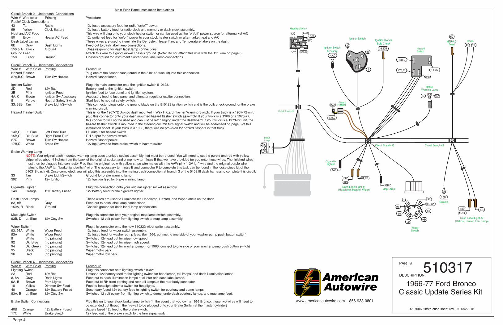
Main Fuse Panel Installation InstructionsCircuit Branch 2 - Underdash ConnectionsWire # Wire color Printing ProcedureRadio/ Clock Connections43 Tan Radio 12v fused accessory feed for radio “on/off” power. 99 Yellow Clock Battery 12v fused battery feed for radio clock and memory or dash clock assembly.Heat and A/C Feed This wire will plug onto your stock heater switch or can be used as the “on/off” power source for aftermarket A/C50 Brown Heater AC Feed 12v switched feed for “on/off” power to your stock heater switch or aftermarket heat and A/C. Dash Label Lamps These wires are used to illuminate the Defroster, Heater Fan, and Temperature labels on the dash.8B Gray Dash Lights Feed out to dash label lamp connections.150 & A Black Ground Chassis ground for dash label lamp connections.Ground Lead Attach this wire to a good known chassis ground. (Note: Do not attach this wire with the 151 wire on page 5) 150 Black Ground Chassis ground for instrument cluster dash label lamp connections.
Circuit Branch 3 - Underdash ConnectionsWire # Wire Color Printing ProcedureHazard Flasher Plug one of the flasher cans (found in the 510145 fuse kit) into this connection.27A,B,C Brown Turn Sw Hazard Hazard flasher leads.
Ignition Switch Plug this main connector onto the ignition switch 510128. 2D Red 12v Bat Battery feed to the ignition switch.3B Pink Ignition Feed Ignition feed to fuse panel and ignition system.4A, C Brown Ignition Sw Accessory Accessory feed to fuse panel and altenator regulator exciter connection.5 Purple Neutral Safety Switch Start feed to neutral safety switch.33, 33B Tan Brake Light/Switch This connector plugs onto the ground blade on the 510128 ignition switch and is the bulb check ground for the brake warning circuit.Hazard Flasher Switch This is for the 1967-72 Bronco dash mounted 4 Way Hazard Flasher Warning Switch. If your truck is a 1967-72 unit, plug this connector onto your dash mounted hazard flasher switch assembly. If your truck is a 1966 or a 1973-77, this connector will not be used and can just be left hanging under the dashboard. If your truck is a 1973-77 unit, the hazard flasher switch is mounted in the steering column turn signal switch and will be addressed on page 5 of this instruction sheet. If your truck is a 1966, there was no provision for hazard flashers in that truck.14B,C Lt. Blue Left Front Turn LH output for hazard switch.15B,C Dk. Blue Right Front Turn RH output for hazard switch.27C Brown Turn Sw Hazard Hazard flasher power.17B,C White Brake Sw 12v input/overide from brake switch to hazard switch.
Brake Warning Lamp NOTE: Your original dash mounted warning lamp uses a unique socket assembly that must be re-used. You will need to cut the purple and red with yellow stripe wires about 4 inches from the back of the original socket and crimp new terminals B that we have provided for you onto those wires. The finished wires must then be plugged into connector F so that the original red with yellow stripe wire mates with the AAW pink “12V ign” wire and the original purple wire mates to the AAW tan “brake light/switch” wire. The necessary terminals B and connector F to complete this task can be found in the loose piece kit of the 510318 dash kit. Once completed, you will plug this assembly into the mating dash connection at branch 3 of the 510318 dash harness to complete this circuit.33 Tan Brake Light/Switch Ground for brake warning lamp.39D Pink 12v Ignition 12v Ignition feed for brake warning lamp.
Cigarette Lighter Plug this connection onto your original lighter socket assembly.140 Orange 12v Battery Fused 12v battery feed for the cigarette lighter.
Dash Label Lamps These wires are used to illuminate the Headlamp, Hazard, and Wiper labels on the dash.8A, 8B Gray Feed out to dash label lamp connections.150A, B Black Ground Chassis ground for dash label lamp connections.
Map Light Switch Plug this connector onto your original map lamp switch assembly.53B, D Lt. Blue 12v Ctsy Sw Switched 12 volt power from lighting switch to map lamp assembly.
Wiper Switch Plug this connector onto the new 510322 wiper switch assembly.93, 93A White Wiper Feed 12v fused feed for wiper switch assembly.93A White Wiper Feed 12v fused feed for washer pump lead. (for 1966, connect to one side of your washer pump push button switch) 91 White (no printing) Switched 12v lead out for wiper low speed.92 Dk. Blue (no printing) Switched 12v lead out for wiper high speed.94 Dk. Green (no printing) Switched 12v lead out for washer pump. (for 1966, connect to one side of your washer pump push button switch)95 Black (no printing) Wiper motor park.96 Red (no printing) Wiper motor low park.
Circuit Branch 4 - Underdash ConnectionsWire # Wire Color Printing ProcedureLighting Switch Plug this connector onto lighting switch 510321.2A Red 12v Bat Unfused 12v battery feed to the lighting switch for headlamps, tail lmaps, and dash illumination lamps.8, 8A Gray Dash Lights Feed out to dash illumination lamps at cluster and dash label lamps.9A, B Brown Park Lights Feed out to RH front parking and rear tail lamps at the rear body connector.10 Yellow Dimmer Sw Feed Feed to headlight dimmer switch for headlights.40 Orange 12v Batttery Fused Secondary fused 12v battery feed to lighting switch for courtesy and dome lamps.53A, B Lt. Blue 12v Ctsy Sw Switched 12 volt power from lighting switch to dome, underdash courtesy lamps, and map lamp feed.
Brake Switch Connections Plug this on to your stock brake lamp switch (In the event that you own a 1966 Bronco, these two wires will need to be extended out through the firewall to be plugged onto your Brake Switch at the master cylinder)40B Orange 12v Battery Fused Battery fused 12v feed to the brake switch.17C White Brake Switch 12v feed out of the brake switch to the turn signal switch.
Main Fuse Panel Installation Instructions ProcedureCircuit Branch 4 - Underdash ConnectionsWire # Wire Color Printing ProcedureTurn Signal Switch Connection Plug into steering column turn signal connection. If you are using a stock Ford steering column on your vehicle, refer to “Table A - AAW turn signal wires to stock turn signal switch wires” on page 8 for proper mating directions. This kit is designed to function with a GM style turn signal switch. Our connector mates to a 3 7/8 inch long plug used on 1969-1974 GM, IDIDIT, many other aftermarket steering columns. Starting from 1975 on up, the GM switch changed and began using a 4 1/4 inch connector. That connector is from the same family and uses the same terminals. By using the supplied mating connector and terminals located in the loose piece kit bag of this dash harness (510318), it is easy to adapt any steering column to the kit. The function of the wires are as follows:14A, B Lt. Blue Left Front Turn LH front turn signal feed out to front light and dash cluster connections.15A, B Dk. Blue Right Front Turn RH front turn signal feed out to front light and dash cluster connections.16B Purple Turn Switch Feed Turn signal 12v feed into column from flasher.17A Lt. Blue Third Brake Lt. 12v feed for third brake light to rear body connector.17B White Brake Sw 12v input from brake switch to turn switch for rear brake lights.18 Yellow Left Rear Turn LH rear turn signal feed out to rear body connection.19 Dk. Green Right Rear Turn RH rear turn signal feed out to rear body connection.27B Brown Turn Sw Hazard Hazard switch 12v feed into column from flasher.28 Black Horn Relay Ground Steering column horn ground to horn relay.28A Black Horn Relay Ground Steering column horn ground to horn relay. Attach this wire to a good known chassis ground.
Circuit Branch 5 - Underdash ConnectionsWire # Wire color Printing ProcedureLH Courtesy Connection Plug in 1 Courtesy lamp extension (as found on page 2 of this instruction set) to complete this circuit.53A,C Lt. Blue 12v Ctsy Sw Switched 12 volt power for LH underdash courtesy lamp and feed to RB harness for dome lamp.156A White Ctsy Ground LH underdash courtesy ground.
Ground Lead Attach this wire to a good known chassis ground. (Note: Do not attach this wire with the 150 wire on page 4) 151 Black/White Speedo Ground Chassis ground for instrument cluster electric speedo connection.
Flasher Plug the other of the flasher cans (found in the 510145 fuse kit) into this connection.16A, B Purple Turn Switch Feed Turn signal flasher leads.
Instrument Cluster Connections These connections will plug into the Cluster Connection Kit, 510319. Specific connections are addressed in that kit.4C Brown (no printing) 12v accessory feed to the cluster for the constant voltage unit for use with stock gauges.8 Gray Dash Lights Feed out from the lighting switch for dash illumination lamps to cluster connection.11B Lt. Green Hi Beam Indicator Light 12v feed to dash cluster for high beam indicator lamp to cluster connection.14C Lt. BLue Left Turn Ind 12v feed to dash cluster for left front turn indicator lamp to cluster connection.15C Dk. Blue Right Turn Ind 12v feed to dash cluster for right front turn indicator lamp to cluster connection.30 Tan Gas Gauge Fuel sender signal from rear body harness or dual tank switch connection to cluster connection.31 Dk. Blue Oil Pressure Oil pressure signal from engine harness lead to cluster connection.35 Dk. Green Temp Sender Temperature sender signal from engine harness lead to cluster connection.39B,C Pink 12v Ign Fused Fused 12v Ignition feed to cluster connection for any aftermarket 12v gauges, then on to the back up switch.121 White Coil Tach Tach sender signal wire from engine harness lead to the cluster connection.139 Pink/White Speedo Power Fused 12v Ignition feed for electric speedometer to cluster connection.150B Black Ground Gauge cluster ground to cluster connection.151 Black Ground Electric speedometer ground to cluster connection.400 Yellow VSS Ground VSS ground from engine harness to cluster connections for electric speedometer.401 Purple VSS Signal VSS signal from engine harness to cluster connections for electric speedometer. 402 Purple/White VSS Power VSS 12v fused power from cluster connections to engine harness leads for electric speedometer.
Fuel Tank Switch If your truck has dual fuel tanks, plug the three fuel tank switch connectors onto your selector switch as shown in Figure F at the top of this page, then install the tank selector switch back into your dashboard. This connection will allow you to switch your gas gauge from one tank sending unit to the other and get an accurate reading. If your truck only has a single fuel tank, plug the tan 30B wire with the black connector into the mating black connector on the tan 30A wire. No other connections are necessary.30 Tan Gas Gauge Gas gauge feed to the dash cluster connector.30A Tan Gas Gauge Gas gauge jumper feed wire from dash cluster connector to main sending unit feed wire in rear body connector.30B Tan Gas Gauge Main gas gauge sending unit feed wire to dual tank switch or to tan 30A jumper feed wire from rear body connector.30C White Gas Gauge Aux Tank Auxiliary gas gauge sending unit feed wire to dual tank switch from rear body connector.
Circuit Branch 6 - Underdash ConnectionsWire # Wire Color Printing ProcedureRear Body Connection This connector will plug into the Rear Body Kit, 510320. Specific connections are addressed in that kit. These wires will pass out to the engine bay through the LH driver’s side firewall grommet as seen on page 10, Figure C.9B,C Brown Rear Running Lights Feed out from headlight switch for tail and tag lamps and feed out to the LH front parking lamp. 17A Lt. Blue Third Brake Light Feed from the brake lamp switch for optional 3rd brake lamp.18 Yellow Left Rear Turn Feed out to the LH rear stop and turn lamp from the turn signal switch.19 Dk. Green Right Rear Turn Feed out to the RH rear stop and turn lamp from the turn signal switch.24 Lt. Green Back Up Lt Sw Feed out to the back up lamps (if so equipped) from the back up switch.30B Tan Gas Gauge Main fuel tank sender signal wire between the rear body and cluster connections.30C Tan Gas Gauge Aux Tank Auxiliary fuel tank sender signal wire between the rear body and cluster connections.40A Orange 12v Battery Fused 12v battery feed for LED lamps.53C Lt. Blue 12v Ctsy Sw 12v switched courtesy feed from the lighting switch for the dome lamp. www.americanautowire.com 856-933-0801
Note:This VSS requires a lead wire from the red wire to a 12 volt ignition source. This wire is notincluded in the kit.
VEHICLE SPEED SENSOR (16000 pulse)
30
3539B,C
31
150
121401402
401402
400
8
pink(12V ignition)
LEFT TURN IND HIGH BEAM IND RIGHT TURN IND
GRD IGRD
S
I
GRD
TYPICAL BLADE TYPE GAUGE CONNECTIONS
GRD GRD
S S
I I
GRDS
I
LAMP CONNECTIONS
white purple(tach - coil) (VSS Signal)
purple/white(VSS Power)
dk blue(oil pressure)
(fuel gauge)
black(ground)
black(ground)
SI
tan
Tachometer Speedometer Oil
Oil Fuel
FuelWater
Volts
Volts
Water SpeedometerTachometer
dk green(temperature)
black(ground)
black(ground)
gray(dash lights)
gray(dash lights)
Blac
kW
hite
Black
Red
pink(12V ignition)
www.americanautowire.com 856-933-0801
White
Circuit Branch 5 - Instrument Cluster WiringShown is a typical installation with electric gauges and an electronic speedometer and tachometer.
Mechanical speedometers will only require the light leads. The VSS lead wires can be ignored for
mechanical speedometers. Always check the manu-facturers instructions for specific requirements.
Branch 5Circuit
VSS Ground VSS Signal
VSS Power
Note: Your VSS Signal and Ground wires have been twisted together from the
factory and must remain this way to shield out any outside
electrical interference that may create an issue with the
proper operation of your electric speedometer.
Ground151
14C139 151 15C11B
PART #
DESCRIPTION:
1966-77 Ford BroncoClassic Update Series Kit
510317
92970069 instruction sheet rev. 0.0 6/4/2012
(electric speedo)
Cluster Connections
139
150B151 402 401
400
PACK CONPACK CON
x
84C
14C11B
15C121
3135
3039B,C
Page 7www.americanautowire.com 856-933-0801
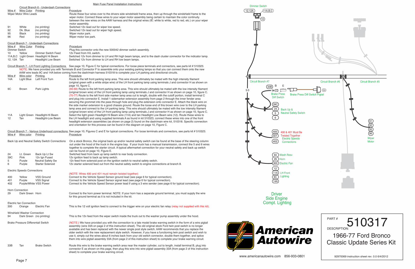
Main Fuse Panel Installation Instructions Circuit Branch 6 - Underdash Connections Wire # Wire Color Printing ProcedureWiper Motor Wire Leads Route these four wires over to the drivers side windshield frame area, then up through the windshield frame to the wiper motor. Connect these wires to your wiper motor assembly being certain to maintain the color continuity between the new wires on the AAW harness and the original wires (IE: white to white, red to red, etc.) on your wiper motor assembly.91 White (no printing) Switched 12v lead out for wiper low speed.92 Dk. Blue (no printing) Switched 12v lead out for wiper high speed.95 Black (no printing) Wiper motor park.96 Red (no printing) Wiper motor low park.
Circuit Branch 7 - Underdash ConnectionsWire # Wire Color Printing ProcedureDimmer Switch Plug this connector onto the new 500042 dimmer switch assembly.10 Yellow Dimmer Switch Feed 12v Feed from H/L switch.11A,B,C Light Green Headlight Hi Beam Switched 12v from dimmer to LH and RH high beam lamps, and to the dash cluster connector for the indicator lamp. 12, 12A Tan Headlight Low Beam Switched 12v from dimmer to LH and RH low beam lamps.
Circuit Branch 7 - LH Front Lighting Connections See page 10, Figure C for typical connections. For loose piece terminals and connectors, see parts kit # 510323. NOTE: We have provided you with Terminals B and Connector F to assemble onto your existing parking lamps so that you can connect them onto the new AAW wire leads 9C and 14A below coming from the dash/main harness 510318 to complete your LH parking and directional circuits.Wire # Wire color Printing Procedure14A Light Blue Left Front Turn Route to the left front parking lamp area. This wire should ultimately be mated with the high intensity filament (original green with a white stripe wire) of the LH front parking lamp using terminals J and connector H as shown on page 10, figure C.9C Brown Park Lights (66-69) Route to the left front parking lamp area. This wire should ultimately be mated with the low intensity filament (original brown wire) of the LH front parking lamp using terminals J and connector H as shown on page 10, figure C. (70-77) Route to the left front side marker lamp area cut to length, double with the cutoff portion, install terminal C and plug into connector E. Install 1 sidemarker extension assembly from page 2 through the inner fender area securing the grommet into the pass through hole and plug the extension onto connector E. Attach the black wire on the side marker extension to a good chassis ground. Route the loose end of this brown wire over to the LH parking lamp area and connect to the LH parking lamp. This wire should ultimately be mated with the low intensity filament (original brown wire) of the LH front parking lamp using terminals J and connector H as shown on page 10, figure C.11A Light Green Headlight-Hi Beam Select the light green Headlight Hi Beam wire (11A) and tan Headlight Low Beam wire (12). Route these wires to 12 Tan Headlight-Low Beam the LH headlight and using supplied terminals A as found in kit 510323, connect these wires into one of the front headlight extension assemblies (as shown on page 2) found on the dash/main wire kit, 510318. Specific connection and orientation for this process can be found in the diagram on page 10, Figure C.
Circuit Branch 7 - Various Underhood connections See page 10, Figures C and E for typical connections. For loose terminals and connectors, see parts kit # 510323. Wire # Wire color Printing Procedure
Back Up and Neutral Safety Switch Connections On a stock Bronco, the original back up and/or neutral safety switch can be found at the base of the steering column out under the hood of the truck in the engine bay. If your truck has a manual transmission, connect the 5 and 6 wires together to complete the starter circuit. A typical aftermarket connection for your neutral safety and back up switch can be found on page 10, Figure E.24 Lt. Green Back Up Lt Sw Switched feed from back up lamp switch to rear body connection. 39C Pink 12v Ign Fused 12v ignition feed to back up lamp switch.5 Purple Neutral Safety Sw 12v feed from solenoid post on the ignition switch to neutral safety switch.6 Purple Starter Solenoid 12v starter solenoid feed out from the neutral safety switch to engine connections at branch 8.
Electric Speedo Connections (NOTE: Wires 400 and 401 must remain twisted together)400 Yellow VSS Ground Connect to the Vehicle Speed Sensor ground lead (see page 6 for typical connection).401 Purple VSS Signal Connect to the Vehicle Speed Sensor signal lead (see page 6 for typical connection).402 Purple/White VSS Power Connect to the Vehicle Speed Sensor power lead if using a 3 wire sender (see page 6 for typical connection).
Horn Connection29 Dark Green Horn Connect to the horn power terminal. NOTE: If your horn has a separate ground terminal, you must supply the wire for this ground terminal as it is not included in the kit.
Electric fan Connection300 Orange Electric Fan This is the 12 volt ignition feed to connect to the trigger wire on your electric fan relay (relay not supplied with this kit).
Winshield Washer Connection94 Dark Green (no printing) This is the 12v feed from the wiper switch inside the truck out to the washer pump assembly under the hood.
Brake Pressure Differentail Switch (NOTE:) We have provided you with the connection to a late model brake warning switch in the form of a wire pigtail assembly (wire 33A on page 2 of this instruction sheet). The old original stock Ford twin post switch is no longer available and has been replaced with the newer single post style switch. AAW recommends that you replace the older switch with the new replacement style switch. However, if you have a functioning twin post switch and wish to use it, simply cut the wires about 6 inches back from your old switch connector, double them together, and splice them into wire pigtail assembly 33A (from page 2 of this instruction sheet) to complete your brake warning circuit.
33B Tan Brake Switch Route this wire to the brake warning switch area near the master cylinder, cut to length, install terminal B, plug into connector E as shown on this page, then plug this wire into wire pigtail assembly 33A (from page 2 of this instruction sheet) to complete your brake warning circuit.
NOTE: On this page, you will find a photograph of the completed fusebox and dash harness assembly as it would install in your vehicle. This harness cannot be used with
the stock dash speaker as the new AAW fuse panel installs in the same location as the stock radio speaker does. You will need to purchase and modify a new glovebox
assembly from the Bronco Graveyard, their part number 17155 (or equilalent), in order to mount this harness in your truck. A template (92970085) to modify the new glove
box asssembly has been included with this kit. We have provided 4 attaching nuts for you to affix the fusebox to the inside of the glove box. They can be found in the
510318 loose piece dash kit. With the new fuse panel assembly mounted inside the glovebox liner, the main bundle or trunk of the new AAW dash harness assembly
should be heading toward the firewall away from the front of the dashboard assembly.
FUSEBOX MOUNTING LOCATION ON THE LH INSIDE OF THE GLOVEBOX
PART #
DESCRIPTION:
1966-77 Ford BroncoClassic Update Series Kit
510317
92970069 instruction sheet rev. 0.0 6/4/2012
AAW AAW AAW FordWire # Wire color Wire Printing Wire Color14A,B Light Blue Left Front Turn Green with white stripe.15A,B Dark Blue Right Front Turn White with blue stripe.16B Purple Turn Switch Feed Blue.17A,B Blue & White Brake Switch Red with black stripe.18 Yellow Left Rear Turn Yellow.19 Dark Green Right Rear Turn Dark Green.27B Brown Turn Sw - Hazard Not applicable.28 Black Horn Relay Ground Yellow.28A Black Horn Relay Ground Blue with yellow stripe.
AAW AAW AAW FordWire # Wire color Wire Printing Wire Color
“Table A” AAW Turn Signal Switch wires to
stock 1972-77 Ford Bronco turn signal switch.
“Table A” AAW Turn Signal Switch wires to
stock 1966-71 Ford Bronco turn signal switch.
NOTE: Ford originally switched 12v power to the horns through the steering column horn button during these years. The AAW kit switches ground through the steering column horn button which
grounds a horn relay that switches the power to the horns.
14A,B Light Blue Left Front Turn Green with white stripe.15A,B Dark Blue Right Front Turn White with blue stripe.16B Purple Turn Switch Feed Blue.17A,B Blue & White Brake Switch Red with black stripe.18 Yellow Left Rear Turn Yellow.19 Dark Green Right Rear Turn Dark Green.27B Brown Turn Sw - Hazard White with red stripe.28 Black Horn Relay Ground Blue with yellow stripe.28A Black Horn Relay Ground Not applicable.
NOTE: The 1972-77 Bronco steering column did not switch power through the column. The steering column horn button switched ground to a horn relay which switches power to the horns just as your new AAW harness does, therefore the 28A
wire is not needed, nor will it be used in this application.
right turn signal lead(not included)
D
G
B F H J
J
NOTE: After making a new 1 1/2” hole in the passenger side of the firewall, install one of
the (2) large main grommets G that have been included in the 510323 kit into that new
firewall pass thru opening, then pass the wiring from branch 8 thru that opening with the grommet installed in it. After completing these
tasks, apply silicone sealer to this area to make a weather tight seal.
RH head lamp, RH parking lamp, engine, main power, alternator ignition, and starter solenoid connections.
NOTE: The terminals and connectors listed on this page and denoted with UPPER CASE LETTERS to help you complete the various connections to your
lamps, engine connections, switches, etc. can be found in your loose piece clamp, grommet, and parts kit, P/N
510323.
The identifications, colors, and functions for all of the wires listed in “Figures A and B” on this page can be found on page 3, branch 2 and branch 8 of this main instruction set (9270069). AAW suggests and recom-
mends using pages 3 and 9 to complete the installation of the foward lamp, engine, alternator ignition, starter
solenoid, and heater connections.
This AAW kit is engineered to work with most aftermar-ket manufacturer’s heating and air conditioning sys-
tems. As such, we have provided a keyed 12-volt feed to use as the “OFF / ON” (AAW brown 50 wire) power source for whatever system you choose to purchase. The manufacturer will supply you with a harness for
their system and instructions on how to connect it. In the event you are utilizing a stock heater system in your truck, we have also provided wires that will run from
your heater switch to your heater resistor and then on to your blower motor. See “Figure B” below for complete
installation instructions.
www.americanautowire.com 856-933-0801
Page 9
(optional)
N
K
choke feed
ballastresistor
(resistor not included.
(this wire not supplied)
(optional typical points type system shown here)
Used on point type and someaftermarket ignition systems)oil sending
to coil “+” side coil
electric
P B
unit
CC Q
E
S IS I
purple
P B
B R(optional)
N
dk blue
brown
Figure “B”, Stock Heater Switch,
Heater Resistor
Heater Switch
High SpeedConnection
Low SpeedConnection
Loose AAW Heater Wire Extensions from Page 2
AAW wire 50, 12 volt feed wire from page 3, branch 2
production heatercable assembly (located on top of heater
plenum behind glovebox)
(production blower motor wire assembly, this lead is not
included with this kit)
Heater switch wire connections as viewed from the back of the stock Ford heater switch.
Resistor, and Blower Motor Connections
H
B
L
PART #
DESCRIPTION:
1966-77 Ford BroncoClassic Update Series Kit
510317
92970069 instruction sheet rev. 0.0 6/4/2012
Figure “A”, Branch #8 Passenger’s Side Location
lt green
tan
black
right headlight
AA
lt greentan
red
to TACH “-” location on coil
white
pink
white
distributor
to BAT “+”location on coil
alternator
alternatorignition wire
brown brown dk bluedk blue
temperature sending unit
dk greendk green
These wires are all found at
branch 8, page 3
Plug this completed
red wire into 2J in Figure D
on page 10
tan
(1970-77 only)right side marker
completed side marker extension assembly from page 2E C
(optional GM HEI)
(optional GM HEI)
to horn
to electric fan
to windshieldwasher pump
to brakewarning switch
recommended fan relay(not included in this kit)
(from rear body kit 510320)
(completed brake switch warning
BP
www.americanautowire.com 856-933-0801
Rear Body Leads
Page 10
Figure “E”
Neutral safety and back up switch connections.
Neutral safety
Shown is a typical NSS and Back Up Switch.Back up
wire 6 from branch 7, page 7wire 39C from branch 7, page 7wire 24 from branch 7, page 7 wire 5 from branch 7, page 7
NOTE: The terminals and connectors listed on this page and denoted with UPPER CASE LETTERS to help you complete the various connections to your lamps, horn, brake warning switch, electric fan, back up and neutral safety switch, washer pump, etc. can be found in your loose piece clamp, grommet, and parts kit, P/N 510323. No terminals have been pro-vided for the neutral safety or back up connections.
The identifications, colors, and functions for all of the wires listed in “Figures C, D, and E” on this page can be found on page 7, branch 7, and page 3, branch 8 of this main instruction set (92970069). AAW sug-gests and recommends using pages 3, 7, and 10 to complete the installation of the forward lamp, horn, brake warning switch, electric fan, neutral safety and back up switch, washer pump, and alternator power connections.
AAW kits are all engineered to be used in conjunction with a high output, later model internally regulated, or one wire alternator. We do not suggest or support the use of a stock low amperage generator or alternator as they do not supply sufficient current to recharge the battery in a highly modified truck such as this kit was designed for. AAW suggests Ford Gen III (AAW p/n 500802), GM “SI”, or 1 wire type alternators as good choices to use. Adpaters to complete the con-nection to these style alternators may be purchased separately if needed. Contact AAW for your needs.
Figure “D”
Fusible Link
StarterSolenoid
To alternator ”BAT” stud
"BAT"
(positive cable
Main system power feed and alternator power feed connections.
2J
2H
2
Fusible Link S I
here also)attaches
stud
Main Power and
"BAT"
to starter output stud
S I
D L (large)
Connect to 2B from branch 8, page 3. Wire 2B comes thru the firewall with the engine
wires from branch 8 as shown in Figure A on page 9.
Alternator Wiring
PART #
DESCRIPTION:
1966-77 Ford BroncoClassic Update Series Kit
510317
92970069 instruction sheet rev. 0.0 6/4/2012
alternator
left turn signal lead(not included)
(1970-77 only)left side marker
G
B F H J
J
NOTE: After opening up a 1 1/2” hole in the driver’s side of the firewall, install one of the (2) large main grommets G that have been included in the 510323 kit into that firewall pass thru opening, then pass the wiring from branch 7 as well as
the wiring from the 510320 rear body kit thru that opening with the grommet installed in it. After completing these tasks, apply
silicone sealer to this area to make a weather tight seal.
LH head lamp, LH parking lamp, horn, washer, electric fan relay trigger, brake switch, neutral safety, and back up connections.
BE
E C
lt blue
brown
lt green
tan
black
left headlight
AA
lt greentan
orange
dk green
yellowpurpleto VSS
(electronic speedo only)
(VSS ground)(VSS signal)
(VSS power)
yellowpurple
purplepurple/ white
to VSS(electronic
speedo only)
(VSS ground)(VSS signal)
(VSS power)
tan
These wires are all found at
branch 7, page 7
The yellow and purple wires must stay twisted together as shown above to create a co-ax that will filter any outside interference to the signal on your electric speedometer.
completed side marker extension assembly from page 2
Figure “C”, Branch #7 Driver’s Side Location to neutral safety and
back up lamp switch connections (see detail Figure E
MAIN HARNESS KIT1966-77 Ford Bronco,Classic Update Series
bag
G
51031892970072 instruction rev 0.0 5/30/2012
MAIN HARNESS KIT1966-77 Ford Bronco,Classic Update Series
bag
G
51031992970076 instruction rev 0.0 5/24/2012
Classic Update SeriesINSTRUMENT
66-77 FORD BRONCOHbag
sheet 1
Cla
ssic
Upd
ate
Serie
s
www.ameriacnautowire.com 856-933-0801
CLUSTER KIT
CONNECTOR A (sheet 2)
BROWN Accessory Feed This wire is used to connect 12v switched power to the factory constant voltage unit. After installing the feed wire onto the constant voltage unit, use the remaining wire to connect from the constant voltage unit to the factory fuel, oil, and temperature gauge unit power studs where your original black w/ green stripe wire attached.PINK 12v ignition If your truck is equipped with aftermarket gauges, plug this loose wire into Connector A maintaining color continuity with the mating connector on your dash harness, install components shown on sheet 2, and connect to the proper aftermarket gauges.GREY Instrument Lamps Install components shown on sheet 2, and plug into the instrument lamp holes in the cluster.BLACK Ground Install components shown on sheet 2, and connect to the back of the instrument cluster housing.
CONNECTOR B (sheet 3)DK BLUE Right Turn Indicator Install components shown on sheet 3, and plug into the right turn hole in the cluster.LT BLUE Left Turn Indicator Install components shown on sheet 3, and plug into the left turn hole in the cluster.LT GREEN Hi Beam Indicator Lamp Install components shown on sheet 3, and plug into the high beam indicator hole in the cluster.DK BLUE Oil Gauge Install components shown on sheet 3, and attach onto the oil gauge sender stud where your original white w/ red stripe wire attached.DK GREEN Temp Gauge Install components shown on sheet 3, and attach onto the temperature gauge sender stud where your original red w/ white stripe wire attached. TAN Fuel Gauge Install components shown on sheet 3, and attach onto the fuel gauge sender stud where your original orange wire attached. WHITE Tach (loose wire) If your truck is equipped with an aftermarket tach, plug this loose wire into Connector B maintaining color continuity with the mating connector on your dash harness, install components shown on sheet 3, and plug onto the tachometer.CONNECTOR C (sheet 4) This connector is used when using an aftermarket electronic speedometer only. Follow the manufacturer's instructions when installing these wires. If you are using the stock speedometer, then discard this connector. See page 4 for wire descriptions and typical connections.
*** These are special instructions for connecting your wiring system to a stock instrument cluster. ***
Note: If you are using aftermarket gauges, follow the instructions included in the 92965220 Gauge Connection Kit along with the specific gauge manufacturers instructions for connection of their gauges.If you are using the stock gauges and warning lamps, refer to the diagrams on the following pages for your application. Use the enclosed parts and information below for wire termination, gauge, and lamp connections. Connectors A, B, and C will plug into your dash harness at branch 5 as noted on the Dash Harness instruction (92970069, bag G) sheet. Connection C will only be used in the event that you are using an electric speedometer.
sheet 2 92970076 instruction rev 0.0 5/24/2012
1966-1977 FORD
instrument lamps
CONNECTOR A
CONNECTOR A (sheet 2)
BROWN Accessory Feed This wire is used to connect 12v switched power to the factory constant voltage unit. After installing the feed wire onto the constant voltage unit, use the remaining wire to connect from the constant voltage unit to the factory fuel, oil, and temperature gauge unit power studs where your original black w/ green stripe wire attached.PINK 12v ignition If your truck is equipped with aftermarket gauges, plug this loose wire into Connector A maintaining color continuity with the mating connector on your dash harness, install components shown on sheet 2, and connect to the proper aftermarket gauges.GREY Instrument Lamps Install components shown on sheet 2, and plug into the instrument lamp holes in the cluster.BLACK Ground Install components shown on sheet 2, and connect to the back of the instrument cluster housing.
CONNECTOR B (sheet 3)DK BLUE Right Turn Indicator Install components shown on sheet 3, and plug into the right turn hole in the cluster.LT BLUE Left Turn Indicator Install components shown on sheet 3, and plug into the left turn hole in the cluster.LT GREEN Hi Beam Indicator Lamp Install components shown on sheet 3, and plug into the high beam indicator hole in the cluster.DK BLUE Oil Gauge Install components shown on sheet 3, and attach onto the oil gauge sender stud where your original white w/ red stripe wire attached.DK GREEN Temp Gauge Install components shown on sheet 3, and attach onto the temperature gauge sender stud where your original red w/ white stripe wire attached. TAN Fuel Gauge Install components shown on sheet 3, and attach onto the fuel gauge sender stud where your original orange wire attached. WHITE Tach (loose wire) If your truck is equipped with an aftermarket tach, plug this loose wire into Connector B maintaining color continuity with the mating connector on your dash harness, install components shown on sheet 3, and plug onto the tachometer.CONNECTOR C (sheet 4) This connector is used when using an aftermarket electronic speedometer only. Follow the manufacturer's instructions when installing these wires. If you are using the stock speedometer, then discard this connector. See page 4 for wire descriptions and typical connections.
Cla
ssic
Upd
ate
Serie
s
xx
12v ignition feed used
BRONCO
(not supplied with kit)
to cluster housing(ground)
to constant
constant voltage unitcustomer’s original
keyed 12v feed
feed from constant
voltage unit
voltage unit to factoryfuel, temp, and oil gauges tach and/or gauges
only with aftermarket
greypink
brown
brown
black
sheet 3 92970076 instruction rev 0.0 5/24/2012
tan
dk green
LH turnRH turn hi beam
lt bluelt greendk blue
Tach feed wire
Cla
ssic
Upd
ate
Serie
s
CONNECTOR B
wire in HEREplug white tach
xx
(aftermarket) (original orange wire)to fuel gauge sender post
(original white/red stripe wire) (original red/white stripe wire)to temp gauge sender post to oil gauge sender post
white
dk blue
1966-1977 FORDBRONCO
sheet 4 92970076 instruction rev 0.0 5/24/2012
Cla
ssic
Upd
ate
Serie
s
TYPICAL ELECTRICSPEEDO CONNECTIONS
x
A B C D E F
Below are some general instructions for hooking up an electric speedometer. This connector and these instructions will ONLY be used in the event that you are utilizing an aftermarket electric speedometer. If your car does NOT have an electric speedometer, this connection will NOT be used and should not be plugged onto your dash harness. It is best to consult the speedometer manufacturer’s instructions if you have any questions.
Yellow VSS Ground Connect to VSS “-” on speedometer.
Purple VSS Signal Connect to VSS input on speedometer.
Purple/White VSS Power Connect to 12V power on speedometer.
Black/White Speedo Ground Connect to ground on speedometer.
Pink/White Speedo Power Connect to 12v power on speedometer. NOTE: This wire will double onto the same stud as the purple/white VSS power wire from above.
CONNECTOR C
pinkblack
purplewhite
white
white
yellowyellow
purple
sheet 1
Clas
sic U
pdat
e Se
ries
www.americanautowire.com 856-933-0801510320
92970080 instruction rev 0.0 5/25/2012
REAR BODY KIT
1966-1977 Ford Mbag
Classic Update Series
dk green
brown
brown
lt green
lt green
yellow
lt blue
black
F G
GF
E
D
E
D or E
brown
brown
to standard tank
large sleeve
small sleeve
to dome light
D
Dtan to rh back
up lamp
to lh back up lamp
tail
stop and turn
back up lamp leads
factory RH taillamp leads
1966-1977 Ford Bronco
L K
Q
S
R
tail
stop and turn
H
H
C
C
C
C
C
C
J
JD H
(“12 volt battery fused” - only used with LED tail lamps)Plug into the main connector and maintain continuitywith dash harness.
orange
(“Third brake light” - only used when needed)Plug into the main connector and maintain color andfunction continuity with dash harness. See below for
to third brake light
12v Batteryconstant feed
lt blue
(“12V CTSY SW” - dome lamp feed. Only used when needed)Plug into the main connector and maintain color and function
lt blue
(“Gas gauge aux tank. ” - only used when needed)
white
D H B
A
continuity with dash harness. See below for suggested
suggested connection.
connection.
to license plate lamp
orange
Bronco
factory LH taillamp leads
fuel sender
to auxiliary tankfuel sender
MN
LH sidemarker
(’70-’77 only)
M
P
RH sidemarker
(’70-’77 only)
LK
Plug into the main connector and maintain color and function continuity with dash harness. See below for suggested connection.
lt blue
Clas
sic U
pdat
e Se
ries
sheet 2
92970080 instruction rev 0.0 5/25/2012
NOTE: We have provided you with 2 new factory reproduction rear body inner panel pass through grommets which are located in the loose piece kit contained inside this rear body harness kit (510320). We suggest that before you install any of the new wiring from this rear body kit, that you remove the old grommets from the inner rear tail lamp area of your truck and replace them with the new ones included in this kit to ensure that the wires do not get chaffed when passing them through the inner LH and RH openings inside of the body.
Connect this main connector to the mating connector on the dash harness 510318, bag G. Route the tail lamp, back up lamp, and fuel tank wires out through the LH grommet and hole in the firewall, down the firewall, and to the back of the truck along the inner side of the driver’s frame rail.
LIGHT BLUE Third Brake Light Plug this loose wire into the main connector maintaining color and function continuity with the dash harness (510318), then connect the other end to the third brake lamp if so equipped.
NOTE: You have been provided with molded fuel tank sending unit extensions for both the main (item A) and auxiliary (item B ) fuel tanks which are fully terminated and are ready for installation. Once you have completed the routing and termination of the tan and white (if you have a second tank) fuel tank wires below, plug these extensions A and B onto the tan and white wires per the instructions to complete your fuel tank sender circuits.
TAN Gas Gauge Route this wire to the main fuel tank sending unit, cut to length, install terminal D, plug into connector H as shown on sheet 1, and plug into the tan fuel tank sender extension A from above. Install the completed tan fuel tank sender extension A onto the sender of the main tank and then ground the ring terminal on the black wire of the tan fuel tank extension A to the frame to complete the main fuel tank sender connection.
WHITE Gas Gauge Aux Tank If your truck has an auxiliary fuel tank, plug this loose wire into the main connector maintaining color and function continuity with the dash harness (510318), route the wire to the auxiliary fuel tank sending unit, cut to length, install terminal D, plug into connector H as shown on sheet 1, and plug into the white fuel tank sender extension B from above. Install the completed white fuel tank sender extension B onto the sender of the auxiliary tank and then ground the ring terminal on the black wire of the white fuel tank extension B to the frame to complete the auxiliary fuel tank sender connection.
NOTE: There are 2 different ways to connect the brown wires. The 1966-69 Broncos did not use side marker lamps, whereas the 1970-77 Broncos did use side marker lamps. We have provided 2 side marker lamp pigtails M with ground wire and ring terminal fully terminated that are ready for installation. Please take note of your application and connect the brown wires accordingly.
BROWN Running Lamps (1966-69 Bronco without side marker lamps) Route this wire to the LH tail lamp area, cut to length, double this wire with the cut off portion, install terminal E and plug into connector F in the location shown on sheet 1. Route the loose end of this brown wire to the license lamp area, cut to length, double this wire with the cut off portion, install terminal K and slide rubber sleeve L back over terminal K as shown on sheet 1. Route the loose end of this brown wire to the RH tail lamp area, cut to length, install terminal D and plug into connector F in the location shown on sheet 1.
(1970-77 Bronco with side marker lamps) Route this wire to the LH side marker lamp area, cut to length, double this wire with the cut off portion, install terminal N and plug into into the empty cavity of one of the side marker pigtails M shown on sheet 1. Route the loose end of this wire to the LH tail lamp area, cut to length, double this wire with the cut off portion, install terminal E and plug into connector F in the location shown on sheet 1. Route the loose end of this brown wire to the license lamp area, cut to length, double this wire with the cut off portion, install terminal K and slide rubber sleeve L back over terminal K as shown on sheet 1. Route the loose end of this brown wire to the RH tail lamp area, cut to length, install terminal E and plug into connector F in the location shown on sheet 1. Route the loose end of this brown wire to the RH side marker lamp area, cut to length, install terminal P and plug into into the empty cavity of the other side marker pigtail M shown on sheet 1.
J
C
H
N
D
E
F
A
B
G
P
KL
1966-1977 Ford Bronco
Q
RS
M
92970080 instruction rev 0.0 5/25/2012
NOTE: We have provided you with 2 new factory reproduction rear body inner panel pass through grommets which are located in the loose piece kit contained inside this rear body harness kit (510320). We suggest that before you install any of the new wiring from this rear body kit, that you remove the old grommets from the inner rear tail lamp area of your truck and replace them with the new ones included in this kit to ensure that the wires do not get chaffed when passing them through the inner LH and RH openings inside of the body.
Connect this main connector to the mating connector on the dash harness 510318, bag G. Route the tail lamp, back up lamp, and fuel tank wires out through the LH grommet and hole in the firewall, down the firewall, and to the back of the truck along the inner side of the driver’s frame rail.
LIGHT BLUE Third Brake Light Plug this loose wire into the main connector maintaining color and function continuity with the dash harness (510318), then connect the other end to the third brake lamp if so equipped.
NOTE: You have been provided with molded fuel tank sending unit extensions for both the main (item A) and auxiliary (item B ) fuel tanks which are fully terminated and are ready for installation. Once you have completed the routing and termination of the tan and white (if you have a second tank) fuel tank wires below, plug these extensions A and B onto the tan and white wires per the instructions to complete your fuel tank sender circuits.
TAN Gas Gauge Route this wire to the main fuel tank sending unit, cut to length, install terminal D, plug into connector H as shown on sheet 1, and plug into the tan fuel tank sender extension A from above. Install the completed tan fuel tank sender extension A onto the sender of the main tank and then ground the ring terminal on the black wire of the tan fuel tank extension A to the frame to complete the main fuel tank sender connection.
WHITE Gas Gauge Aux Tank If your truck has an auxiliary fuel tank, plug this loose wire into the main connector maintaining color and function continuity with the dash harness (510318), route the wire to the auxiliary fuel tank sending unit, cut to length, install terminal D, plug into connector H as shown on sheet 1, and plug into the white fuel tank sender extension B from above. Install the completed white fuel tank sender extension B onto the sender of the auxiliary tank and then ground the ring terminal on the black wire of the white fuel tank extension B to the frame to complete the auxiliary fuel tank sender connection.
NOTE: There are 2 different ways to connect the brown wires. The 1966-69 Broncos did not use side marker lamps, whereas the 1970-77 Broncos did use side marker lamps. We have provided 2 side marker lamp pigtails M with ground wire and ring terminal fully terminated that are ready for installation. Please take note of your application and connect the brown wires accordingly.
BROWN Running Lamps (1966-69 Bronco without side marker lamps) Route this wire to the LH tail lamp area, cut to length, double this wire with the cut off portion, install terminal E and plug into connector F in the location shown on sheet 1. Route the loose end of this brown wire to the license lamp area, cut to length, double this wire with the cut off portion, install terminal K and slide rubber sleeve L back over terminal K as shown on sheet 1. Route the loose end of this brown wire to the RH tail lamp area, cut to length, install terminal D and plug into connector F in the location shown on sheet 1.
(1970-77 Bronco with side marker lamps) Route this wire to the LH side marker lamp area, cut to length, double this wire with the cut off portion, install terminal N and plug into into the empty cavity of one of the side marker pigtails M shown on sheet 1. Route the loose end of this wire to the LH tail lamp area, cut to length, double this wire with the cut off portion, install terminal E and plug into connector F in the location shown on sheet 1. Route the loose end of this brown wire to the license lamp area, cut to length, double this wire with the cut off portion, install terminal K and slide rubber sleeve L back over terminal K as shown on sheet 1. Route the loose end of this brown wire to the RH tail lamp area, cut to length, install terminal E and plug into connector F in the location shown on sheet 1. Route the loose end of this brown wire to the RH side marker lamp area, cut to length, install terminal P and plug into into the empty cavity of the other side marker pigtail M shown on sheet 1.
sheet 3
Clas
sic U
pdat
e Se
ries
YELLOW LH Stop / Tail Route this wire to the LH tail lamp area, cut to length, install terminal D and plug into the empty cavity of connector F as shown on sheet 1. Terminals C and connector G have been provided for you to crimp onto your stop and tail lamp leads to complete the connection to the LH stop, turn, and tail assembly.
DK GREEN RH Stop / Tail Route this wire to the RH tail lamp area, cut to length, install terminal D and plug into the empty cavity of connector F as shown on sheet 1. Terminals C and connector G have been provided for you to crimp onto your stop and tail lamp leads to complete the connection to the RH stop, turn, and tail assembly.
LIGHT GREEN Back Up Lamp Feed Route this wire to the LH back up lamp area, cut to length, double this wire with the cut off portion, install terminal E, and plug into connector H as shown on sheet 1. Route the loose end of this lt green wire over to the RH back up lamp area, cut to length, install terminal D, and plug into connector H as shown on sheet 1. Terminals C and connectors J have been provided for you crimp onto your back up lamp leads to complete the connection to the LH and RH assemblies.
NOTE: The 66 through 74 Broncos had a dome lamp that was grounded through the dome lamp housing which did not require a separate ground wire. The 75 through 77 Broncos did require a separate ground wire. We have provided you with a switched 12v feed wire (light blue) which will be used in either application. We have also provided a separate black ground wire for use with the 74 through 77 Broncos only. Please follow the dome lamp connections that apply to your application as outlined below and in the drawing on sheet 1.
LIGHT BLUE 12V Courtesy Switched (These directions apply to both the 66-74 and 75-77 applications). If your truck utilizes a dome lamp assembly, plug this loose wire into the main connector maintaining color and function continuity with the dash harness (510318), then route this wire up through the windshield frame to the dome lamp unit. If you are using the aftermarket unit that mounts in the back of the truck, you will have to route this wire to the back of the truck as well. Cut the wire to length, slide the larger rubber sleeve L onto the wire, crimp terminal K onto the wire and slide the rubber sleeve back over the terminal to protect the terminal from shorting out against any sheet metal. Install the completed wire assembly onto the dome lamp unit. If your truck is a 66-74 model, your dome lamp circuit is now completed. (This is your dome lamp 12 volt feed wire). If your truck is a 75-77 model, continue onto the next step with the black ground wire.
BLACK Ground (These directions apply to 75-77 applications only, as the 66-74 dome lamp assembly typically has a ground wire attached to it, or is self grounding, so this wire is not used in those applications). If your truck utilizes a dome lamp assembly, route the loose end of wire S up through the windshield frame to the dome lamp unit. If you are using the aftermarket unit that mounts in the back of the truck, you will have to route this wire to the back of the truck as well. Cut the wire to length, slide the smaller rubber sleeve Q onto the wire, then crimp terminal R onto the wire. Slide the rubber sleeve up to the bottom of the terminal so that the bullet end is left exposed. Install this end of your completed wire assembly onto the dome lamp unit assembly pigtail. Attach the other end of this wire (with the ring terminal on it) that comes out the bottom of the windshield frame to a known good chassis ground to complete your dome lamp circuit.
ORANGE 12 Volt Battery Fused If your truck has LED tail lamps that require a full time 12 volt battery feed for memory purposes, plug this loose wire into the main connector maintaining color and function continuity with the dash harness (510318), route this wire to the LH stop, turn, and tail assembly, attach it to the LH lamp assembly per the manufacturer’s instructions, then continue the orange wire on over to the RH stop, turn, and tail assembly and attach it to the RH lamp assembly per the manufacturer’s instructions.
1966-1977 Ford Bronco
J
C
H
N
D
E
F
A
B
G
P
KL
Q
RS
M
Clas
sic U
pdat
e Se
ries
sheet 4
92970080 instruction rev 0.0 5/25/2012
YELLOW LH Stop / Tail Route this wire to the LH tail lamp area, cut to length, install terminal D and plug into the empty cavity of connector F as shown on sheet 1. Terminals C and connector G have been provided for you to crimp onto your stop and tail lamp leads to complete the connection to the LH stop, turn, and tail assembly.
DK GREEN RH Stop / Tail Route this wire to the RH tail lamp area, cut to length, install terminal D and plug into the empty cavity of connector F as shown on sheet 1. Terminals C and connector G have been provided for you to crimp onto your stop and tail lamp leads to complete the connection to the RH stop, turn, and tail assembly.
LIGHT GREEN Back Up Lamp Feed Route this wire to the LH back up lamp area, cut to length, double this wire with the cut off portion, install terminal E, and plug into connector H as shown on sheet 1. Route the loose end of this lt green wire over to the RH back up lamp area, cut to length, install terminal D, and plug into connector H as shown on sheet 1. Terminals C and connectors J have been provided for you crimp onto your back up lamp leads to complete the connection to the LH and RH assemblies.
NOTE: The 66 through 74 Broncos had a dome lamp that was grounded through the dome lamp housing which did not require a separate ground wire. The 75 through 77 Broncos did require a separate ground wire. We have provided you with a switched 12v feed wire (light blue) which will be used in either application. We have also provided a separate black ground wire for use with the 74 through 77 Broncos only. Please follow the dome lamp connections that apply to your application as outlined below and in the drawing on sheet 1.
LIGHT BLUE 12V Courtesy Switched (These directions apply to both the 66-74 and 75-77 applications). If your truck utilizes a dome lamp assembly, plug this loose wire into the main connector maintaining color and function continuity with the dash harness (510318), then route this wire up through the windshield frame to the dome lamp unit. If you are using the aftermarket unit that mounts in the back of the truck, you will have to route this wire to the back of the truck as well. Cut the wire to length, slide the larger rubber sleeve L onto the wire, crimp terminal K onto the wire and slide the rubber sleeve back over the terminal to protect the terminal from shorting out against any sheet metal. Install the completed wire assembly onto the dome lamp unit. If your truck is a 66-74 model, your dome lamp circuit is now completed. (This is your dome lamp 12 volt feed wire). If your truck is a 75-77 model, continue onto the next step with the black ground wire.
BLACK Ground (These directions apply to 75-77 applications only, as the 66-74 dome lamp assembly typically has a ground wire attached to it, or is self grounding, so this wire is not used in those applications). If your truck utilizes a dome lamp assembly, route the loose end of wire S up through the windshield frame to the dome lamp unit. If you are using the aftermarket unit that mounts in the back of the truck, you will have to route this wire to the back of the truck as well. Cut the wire to length, slide the smaller rubber sleeve Q onto the wire, then crimp terminal R onto the wire. Slide the rubber sleeve up to the bottom of the terminal so that the bullet end is left exposed. Install this end of your completed wire assembly onto the dome lamp unit assembly pigtail. Attach the other end of this wire (with the ring terminal on it) that comes out the bottom of the windshield frame to a known good chassis ground to complete your dome lamp circuit.
ORANGE 12 Volt Battery Fused If your truck has LED tail lamps that require a full time 12 volt battery feed for memory purposes, plug this loose wire into the main connector maintaining color and function continuity with the dash harness (510318), route this wire to the LH stop, turn, and tail assembly, attach it to the LH lamp assembly per the manufacturer’s instructions, then continue the orange wire on over to the RH stop, turn, and tail assembly and attach it to the RH lamp assembly per the manufacturer’s instructions.
Part time front parking lamp feed out(not used in this kit)
(not used in this kit)
12 volt battery unfused feed in
12 volt battery fused feed fordome and courtesy
Switched 12 volt courtesy / dome feed out
Headlight feed out
Dash lamp feed out
AD1
D2H
PB
R
File shaft approximately as shown for proper fit on knob
Original dash bezel and nut(Not Included with this kit)
end view
1. Install the new switch into your dash using the original bezel and nut. It will be necessary too cut the shaft for a nice custom installation.2. Install the shaft in switch being certain that it is fully engaged inside the switch.Once the shaft is fully seated down inside the switch in the “off” position, place the knob on end of shaft. Measure how far away from the dash the bottom faceof the knob (closest to dash) is. Allow for 1/4'” or so extra so that the knob will notbottom out on dash once the shaft has been cut to length.3. Remove the shaft from the switch. To do this, pull the shaft completely out to the “on” postion. Reach up under the dash and depress the button on top of the switch and pull the shaft out of the switch. Cut the shaft based on your measurements. It may be necessary to file the end of the shaft once it has been cut in order to reinstall the knob onto the shaft.4. Attach the knob to the cut shaft and tighten the allen screw.5. Reinstall your newly customized shaft into your headlight switch assembly.
GM COLUMN MOUNTDASH MOUNT
PART #
DESCRIPTION:Wiper Switch
1966 - 77 Ford BroncoClassic Update Series
510322
92970087 instruction sheet rev 0.0 5/15/2012
www.americanautowire.com 856-933-0801
1. Install the new switch into your dash using your original bezel and nut. 2. Attach the knob to the shaft and tighten the locking screw.3. Plug the wiper connector from branch 3 of the 92970069 instruction set onto the wiper switch assembly now mounted in the dash to complete the switch installation.
GM COLUMN MOUNTDASH MOUNT
Wiper Switch1966 - 77 Ford BroncoClassic Update Series
510322
92970087 instruction sheet rev 0.0 5/15/2012
www.americanautowire.com 856-933-0801
1. Install the new switch into your dash using your original bezel and nut. 2. Attach the knob to the shaft and tighten the locking screw.3. Plug the wiper connector from branch 3 of the 92970069 instruction set onto the wiper switch assembly now mounted in the dash to complete the switch installation.
GM COLUMN MOUNTDASH MOUNTUNIVERSAL
PART #
DESCRIPTION: Clamp, Grommet, and Parts Kit
1966-77 Ford BroncoClassic Update Series
510323
92970089 instruction sheet rev 0.0 6/1/2012page 1
In this kit you will find the following:1. 2 Main firewall grommets.2. Misc. connectors and terminals to complete engine, alternator, and forward lamp connections.
Some early Broncos had rectangular holes in the firewall behind the engine and a small round hole in the upper driver’s side of the firewall. If your Bronco is configured this way, you will need to open up that driver’s
side hole to 1 1/2” and you will need to make a new 1 1/2” hole on the pasenger’s side as well before installing your new AAW Bronco Classic Update wiring harness. The later Broncos actually used this 1 1/2“ hole
on either side of the firewall configuration. The center rectangular hole will not be used at all and should be closed up in some way. The 2 new main firewall grommets listed above will be used to line the two new or existing
1 1/2” holes. Your LH and RH under hood branches of your dash/main harness (510318) will exit the cab of the truck through these 2 grommets
out into the engine bay. The various terminals and connectors that are included in this bag will be used to complete the many connections under the hood of your Bronco. These detailed installation instructions of how to route the harness and what connectors to install on which wires can be
found on pages 9 and 10 of the main instruction set (92970069).
92970089 instruction sheet rev 0.0 6/1/2012page 2
In the box below, you will find the legend for the misc. terminals, plastic connector bodies, and the main firewall grommets that will be used to complete your main power, forward lighting, engine, and alternator connections. They are itemized and referred to on this page just as they are on pages 9 and 10 of the Main instruction set (92970069).
B
A
F
H
J
M
P
G
N
K
DC
E
L
(smaller 56 series double female terminal)
(56 series single male terminal)
(smaller 56 series single female terminal)
(larger 59 series single female terminal)
(56 series single female conn. with lock wedge)
(56 series single female conn. with notch)
Q (56 series single female HEI power conn.)
R (56 series single female HEI tach conn.)
(”T” shaped 56 series double male connector)
(”T” shaped 56 series double female connector)
(large rubber sleeve)
(2 large main firewall grommets)
(small ring terminal for larger gauge wire)
(small ring terminal for smaller gauge wire)
(large ring terminal)
(small rubber sleeve)
2.67
2.95
TOP
BOTTOM
REAR
FRONT
Drill these four (4) new 3/16” (.1875) holes (marked in red) for
fuseblock attachment.
Cut out and remove white area inside the
red outlined box.
Existing factory hole for“U” Nut
(For reference)
instructions Rev 1.0 8/30/2012
www.americanautowire.com 856-933-0801
92970085
1. You cannot use this harness with a stock radio dash speaker as the new AAW fusepanel mounts in the area where the original speaker was located.2. You will need to purchase a new plastic glovebox liner assembly that does not have a stock fusebox hole in it to mount the new AAW harness into your vehicle.3. Attach this template to the outside of the driver’s side of the glovebox assembly (closest to where the production radio dash speaker was), cut out the white area bordered in red, and drill the four .1875 holes as marked on the template.4. Once your rectangular opening has been cut out and your 4 new holes are drilled, place the new AAW fusepanel thru the opening and attach the fusepanel into that opening using the 4 locking nuts included/supplied in the loose piece parts kit of the 510317 dash/main harness with the harness bundle facing toward the rear of the glovebox as shown above.
Harness bundle heading this direction once the
fusepanel is installed into the glovebox assembly.