36
Doug Traill, GTC17 WARPING & BLENDING FOR MULTI-DISPLAY SYSTEM USING NVIDIA DESIGNWORKS

Doug Traill, GTC17
WARPING & BLENDING FOR MULTI-DISPLAY SYSTEM USING NVIDIA DESIGNWORKS

2
THREE APIS
- Why use NVIDA WARP API
- Linux
- New filtering methods
How to String out a 50 minute talk
3
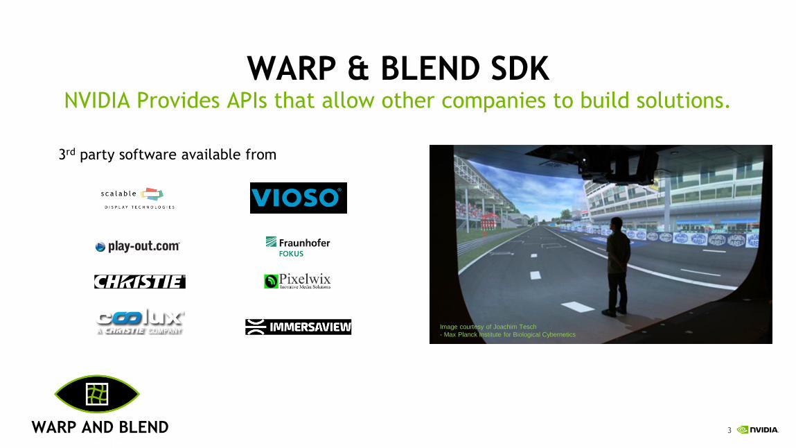
WARP & BLEND SDKNVIDIA Provides APIs that allow other companies to build solutions.
3rd party software available from
Image courtesy of Joachim Tesch
- Max Planck Institute for Biological Cybernetics
WARP AND BLEND

4
CUSTOM HMDS
EXAMPLE USE CASES Used in many different applications
PROJECTION ENVIRONMENTS
LARGE TILED WALLSPROJECTION MAPPING

5
THE CHALLENGEHow do we create a seamless image?
Projectors we can overlap the edges to hide the seams
6
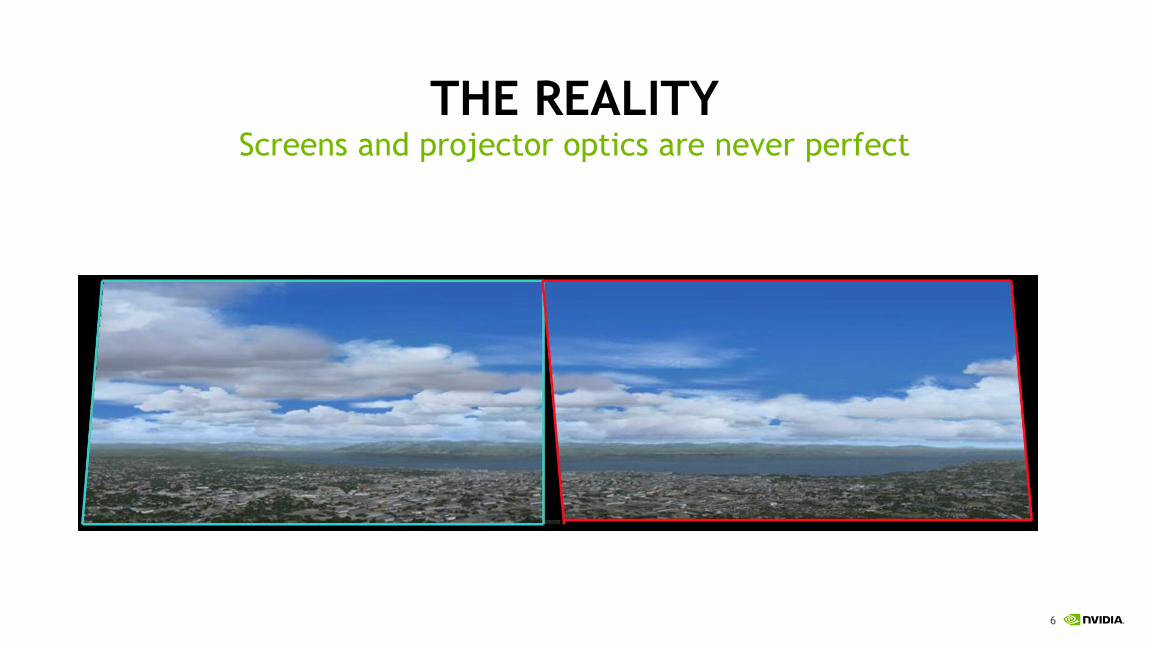
THE REALITYScreens and projector optics are never perfect
7
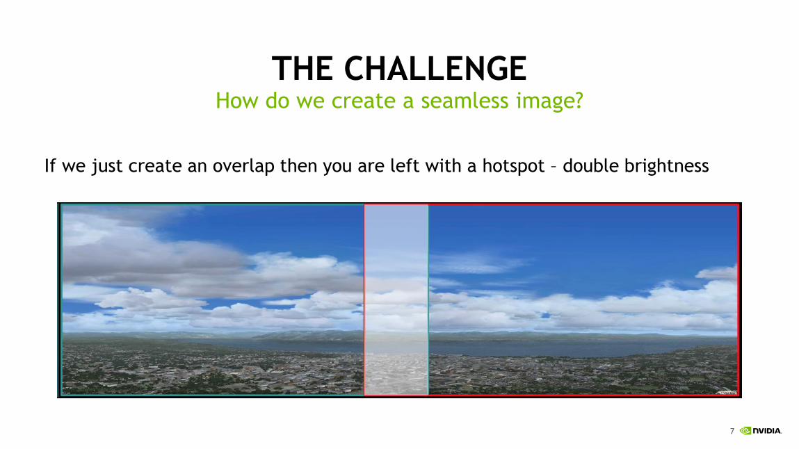
THE CHALLENGEHow do we create a seamless image?
If we just create an overlap then you are left with a hotspot – double brightness

8
NVIDIA SOLUTION
• MOSAIC
• ability to create a uniform desktop with overlap correction.
• overlap correction helps maintain the correct aspect ratio - so a circle looks like a circle
• WARP & Blend
• Warp – Geometry correction – so the projected image matches the display
• Blend – intensity adjustment
• Filtering – smooths aliasing caused by warping the image.
Aimed at developers – we don’t provide our own application

9
CUSTOM SOFTWARE
SPECIALIST PROJECTORS
DEDICATED H/W
HISTORICAL APPROACHES
Expensive
Limited bandwidth – DP1.2
Additional Complexity
Performance Delay
Sometimes built into an application
Performance hit as resolution increases
Not easy to implement –until now.
Limited Choice
Expensive

10
NVIDIA’S SOLUTION
• GPUs are inherently parallel and already have the pixel Information
• Fast for image processing operations
• GPUs are designed for imaging, texturing and raster operations (compared with external boxes using FPGAs)
• Perform the transformation in the display pipeline before the pixels get scanned out
• By doing this on the GPU, we have more flexibility: high quality filtering, integration with SLI Mosaic, etc.
We can do this on the GPU!

11
SUPPORTED ON
Video and basic 3D content
Low profile for SFF systems
Performance 3D content
Single slot FF with Sync support
Video and basic 3D content
Single slot FF with 8 display outputs
Demanding 3D content & Interactivity
Dual slot FF with Sync support
Ultimate 3D performance & Interactivity
Dual slot FF with Sync support
NVS 810
Quadro P1000
Quadro P4000
Quadro P5000
Quadro P6000
2-way SLI support
Quadro SyncII Support – 4 GPUs
Ultimate Double Precision performance
Dual slot FF with Sync support
Quadro GP100
2-way NV-Link

12
HOW ITS DONE: WARP & BLEND WORKFLOW
Different approaches
• Camera based calibration
• GUI alignment
• Pre-defined shapes
Define Warp Mesh
• Define your mesh
• Define the texture co-ordinates to implement distortion
Define the Warp + Blend zone
Typical Mesh is from “4” to “2 million” polygons
13
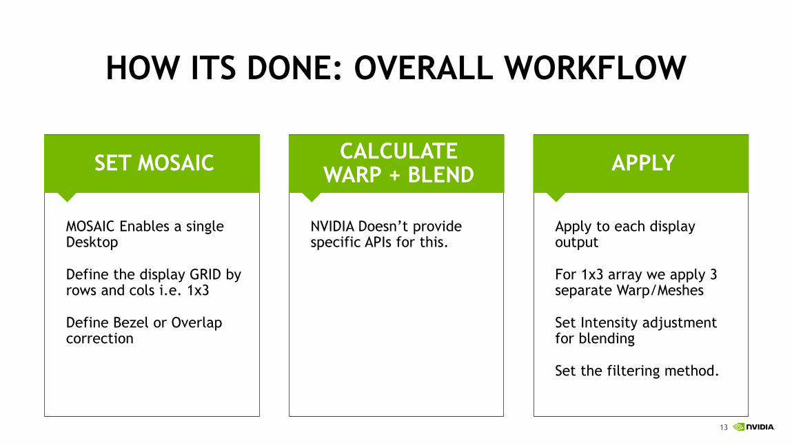
HOW ITS DONE: OVERALL WORKFLOW
APPLYCALCULATE
WARP + BLENDSET MOSAIC
MOSAIC Enables a single Desktop
Define the display GRID by rows and cols i.e. 1x3
Define Bezel or Overlap correction
Apply to each display output
For 1x3 array we apply 3 separate Warp/Meshes
Set Intensity adjustment for blending
Set the filtering method.
NVIDIA Doesn’t provide specific APIs for this.

14
NVAPI
Public & NDA Version
• Public – developer.nvidia.com
• Most functions available – MOSAIC, WARP etc NO Custom Resolution.
NDA – registered developer with NDA. NVIDIA provides access to partner network for download
• All functions available – including custom resolution
• More SDK examples
Structure versions
• Each structure in NVAPI contains a version field that must be set.
• NV_XXX.version = NV_XXX_VER;
displayIds – unique identifier for each display attached. Includes GPU info.
Programmatically on Windows

15
NV-CONTROL
Source code/samples: ftp://download.nvidia.com/XFree86/nvidia-settings/
Samples include:
- nv-control-targets.c - print out system info – including connected displays
- nv-control-dpy.c – different options including generating custom modelines and printing out current modeline in use
- nv-control-framelock.c - Quadro Sync II card setup and control
- nv-control-events.c – Events – including sync events
- nv-control-warpblend.c – Warp and blend sample
Programmatically on Linux
16
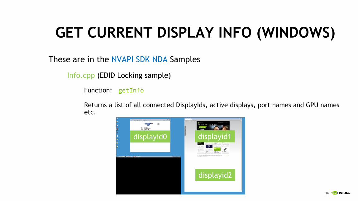
GET CURRENT DISPLAY INFO (WINDOWS)
These are in the NVAPI SDK NDA Samples
Info.cpp (EDID Locking sample)
Function: getInfo
Returns a list of all connected DisplayIds, active displays, port names and GPU names etc.
displayid0 displayid1
displayid2

17
GET CURRENT DISPLAY INFO (LINUX)
Query the number of Xscreens
Query attached displays per Xscreen.
Query attached displays per screen
ret = XNVCTRLQueryTargetBinaryData
(dpy,
NV_CTRL_TARGET_TYPE_GPU,
gpu, // target_id
0, // display_mask
NV_CTRL_BINARY_DATA_XSCREENS_USING_GPU,
(unsigned char **)&pData,
&len);
for (j = 1; j <= pData[0]; j++) {.
screen = pData[j];
ret = XNVCTRLQueryTargetBinaryData
(dpy,
NV_CTRL_TARGET_TYPE_X_SCREEN,
screen, // target_id
0, // display_mask
NV_CTRL_BINARY_DATA_DISPLAYS_ASSIGNED_TO_
XSCREEN,
(unsigned char **)&pDisplayData,
&len);
}
18
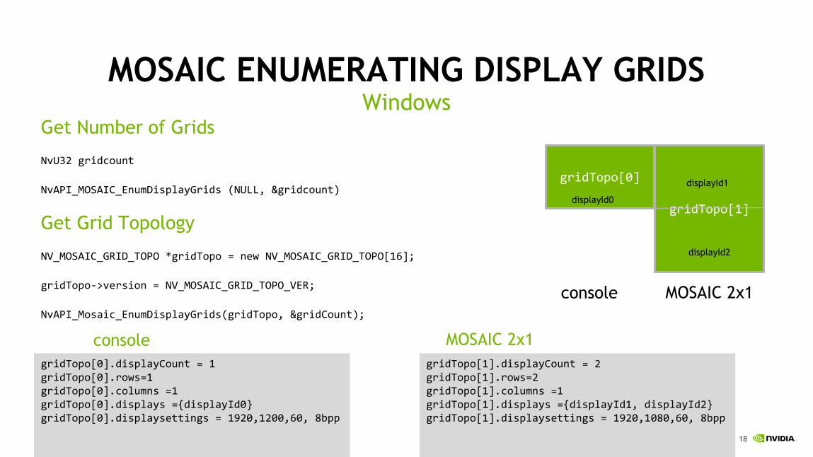
MOSAIC ENUMERATING DISPLAY GRIDS
Get Number of Grids
NvU32 gridcount
NvAPI_MOSAIC_EnumDisplayGrids (NULL, &gridcount)
Get Grid Topology
NV_MOSAIC_GRID_TOPO *gridTopo = new NV_MOSAIC_GRID_TOPO[16];
gridTopo->version = NV_MOSAIC_GRID_TOPO_VER;
NvAPI_Mosaic_EnumDisplayGrids(gridTopo, &gridCount);
Windows
gridTopo[0]
gridTopo[1]
console MOSAIC 2x1
gridTopo[0].displayCount = 1gridTopo[0].rows=1gridTopo[0].columns =1gridTopo[0].displays ={displayId0}gridTopo[0].displaysettings = 1920,1200,60, 8bpp
gridTopo[1].displayCount = 2gridTopo[1].rows=2gridTopo[1].columns =1gridTopo[1].displays ={displayId1, displayId2}gridTopo[1].displaysettings = 1920,1080,60, 8bpp
displayId0
displayId1
displayId2
console MOSAIC 2x1

19
MOSAIC – PSEUDO CODE
Enumerate current grids
Helpful to populate info
no_grid =2
Console display – Grid[0]
Create a 1 by 1 grid
Choose default timings
Grid[1] – this is MOSAIC layout
rows/columns i.e. 4 rows 1 cols (choose based on layout)
Set resolution based on custom timing
NvAPI_Mosaic_SetDisplayGrids(grid, no_grid, 0);
Some Pseudo Code Windows

20
MOSAIC TIPS
• Sort the GPUs based on PCIe slot info
• Enumeration of the GPUs returned by NVAPI is just a list – doesn’t indicate position.
• Enumeration position can change based on configuration.
• For PCIe info
• NvAPI_GPU_GetBusId & NvAPI_GPU_GetBusSlotId
• Validate the display Grid –returns list of failure codes
• NvAPI_Mosaic_ValidateDisplayGrids
• Check for non-mitigating applications
• Apps that are likely to crash when - Multi-GPU MOSAIC is set – general apps running OGL context.
• Includes Chrome browser etc.
• NvAPI_GPU_QueryActiveApps & NvAPI_QueryNonMigratableApps

21
MOSAIC ON LINUXxorg.conf
Single GPU
Option "MetaModes" "1920x1080 +0+0, 1920x1080 +1920+0, 1920x1080 +0+1080, 1920x1080 +1920+1080"Option "nvidiaXineramaInfo" "FALSE"
Dual GPU(no sync)
Option "BaseMosaic" "TRUE"Option "MetaModes" "GPU-0.DFP-0: 1920x1080 +0+0, GPU-0.DFP-1: 1920x1080 +1950+0, GPU-1.DFP-0: 1920x1080 +0+1100, GPU-1.DFP-1: 1920x1080 +1950+1100"Option "nvidiaXineramaInfo" "FALSE"
SLI, NVLINK or Quadro Sync II
Option "SLI" "MOSAIC"Option "MetaModes" "GPU-0.DFP-0: 1920x1080 +0+0, GPU-0.DFP-1: 1920x1080 +1820+0, GPU-1.DFP-0: 1920x1080 +0+1000, GPU-1.DFP-1: 1920x1080 +1820+1000"Option "nvidiaXineramaInfo"
(bezel or overlap)
(bezel or overlap)
(bezel)
22
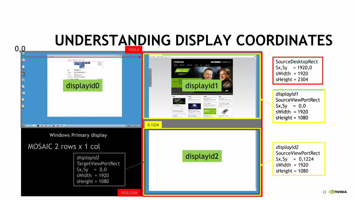
UNDERSTANDING DISPLAY COORDINATES0,0
Windows Primary display
displayid0 displayid1
displayid2
SourceDesktopRect
Sx,Sy = 1920,0
sWidth = 1920
sHeight = 2304
displayid2
SourceViewPortRect
Sx,Sy = 0,1224
sWidth = 1920
sHeight = 1080
displayid1
SourceViewPortRect
Sx,Sy = 0,0
sWidth = 1920
sHeight = 1080
displayid1
SourceViewPortRect
Sx,Sy = 0,0
sWidth = 1920
sHeight = 1080
1920,0
1920,2304
0,1224
MOSAIC 2 rows x 1 col
displayid2
TargetViewPortRect
Sx,Sy = 0,0
sWidth = 1920
sHeight = 1080

23
UNDERSTANDING DISPLAY COORDINATESNvAPI_GPU_GetScanoutConfigurationEx(displayId, scanInfo)
scanInfo.sourceDesktopRect – Sx, Sy, sWidth, sHeight
All displayId that are part of MOSAIC grid will return same sourceDesktopRect.
scanInfo.sourceViewPortRect – Sx, Sy, sWidth, sHeight
Gives the values related to the Desktop size.
scanInfo.targetViewPortRect – Sx, Sy, sWidth, sHeight
Gives the values related to the physical display.

24
LINUX SIMILAR CO-ORDS
Xscreen size
NV_CTRL_STRING_SCREEN_RECTANGLE
Display Size and coordinates
NV_CTRL_BINARY_DATA_DISPLAYS_ENABLED_ON_XSCREEN
// Get resolution of the Xcreen
ret = XNVCTRLQueryStringAttribute(
dpy,
screen,
0,
NV_CTRL_STRING_SCREEN_RECTANGLE,
&str);
ret = XNVCTRLQueryTargetBinaryData
(dpy,
NV_CTRL_TARGET_TYPE_X_SCREEN,
screen, // target_id
0, // display_mask
NV_CTRL_BINARY_DATA_DISPLAYS_ENABLED
_ON_XSCREEN,
(unsigned char **)&pDisplayData,
&len);
You use NVCNTRL to query layout

25
WARP EXAMPLE
26
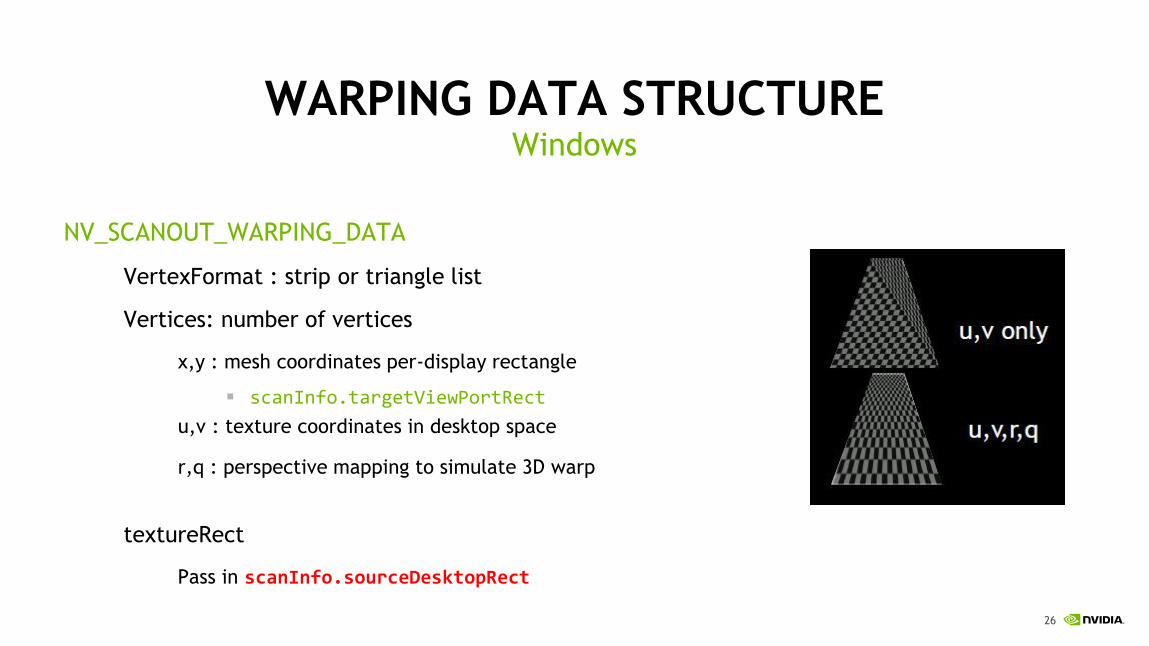
WARPING DATA STRUCTURE
NV_SCANOUT_WARPING_DATA
VertexFormat : strip or triangle list
Vertices: number of vertices
x,y : mesh coordinates per-display rectangle
▪ scanInfo.targetViewPortRect
u,v : texture coordinates in desktop space
r,q : perspective mapping to simulate 3D warp
textureRect
Pass in scanInfo.sourceDesktopRect
Windows
27
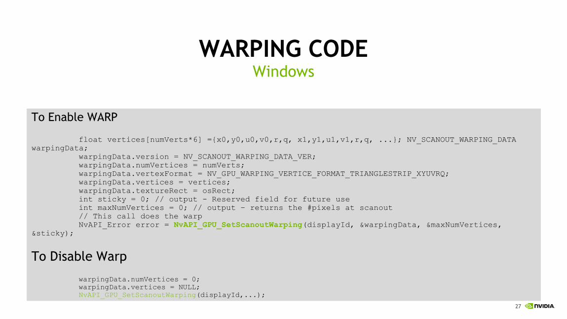
WARPING CODE
To Enable WARP
float vertices[numVerts*6] ={x0,y0,u0,v0,r,q, x1,y1,u1,v1,r,q, ...}; NV_SCANOUT_WARPING_DATA
warpingData;
warpingData.version = NV_SCANOUT_WARPING_DATA_VER;
warpingData.numVertices = numVerts;
warpingData.vertexFormat = NV_GPU_WARPING_VERTICE_FORMAT_TRIANGLESTRIP_XYUVRQ;
warpingData.vertices = vertices;
warpingData.textureRect = osRect;
int sticky = 0; // output - Reserved field for future use
int maxNumVertices = 0; // output – returns the #pixels at scanout
// This call does the warp
NvAPI_Error error = NvAPI_GPU_SetScanoutWarping(displayId, &warpingData, &maxNumVertices,
&sticky);
To Disable Warp
warpingData.numVertices = 0;
warpingData.vertices = NULL;
NvAPI_GPU_SetScanoutWarping(displayId,...);
Windows

28
WARPING CODE
All co-ordinates are normalized – 0.0f to 1.0f
// Prime the random number generator, since the helper functions need it.
srand(time(NULL));
// Apply our transformed warp data to the chosen display.
XNVCTRLSetScanoutWarping(xDpy, screenId, dpyId,
NV_CTRL_WARP_DATA_TYPE_MESH_TRIANGLES_XYUVRQ,
6, // 6 vertices for two triangles
(float *)warpData);
On Linux

29
BLENDING EXAMPLE

30
BLEND/INTENSITY ADJUSTMENTNV_SCANOUT_INTENSITY_DATA
• width, height
• Dimensions of blending texture
• Normally same dimensions as scanout rectangle
• If larger than scanout size, driver dynamically downsamples using box filter
• blendingTexture
• float[width*height*3], RGB with same storage layout as OpenGL
• Set to NULL for no adjustments
• offsetTexture
• Same dimensions as blendingTexture
• offsetTexChannels
• Number of components in the offsetTexture, 1 or 3

31
SAMPLE CODE
NV_SCANOUT_INTENSITY_DATA intensityData;
// simple 1x2 config, overlap region is modulated by 0.5
float intensityTexture[6] = {0.5f, 0.5f, 0.5f, 1.0f, 1.0f, 1.0f} ;
// overlapped region doesn’t require an offset
float offsetTexture[6] = {0.0f, 0.0f, 0.0f, 0.1f, 0.1f, 0.1f} ;
intensityData.version = NV_SCANOUT_INTENSITY_DATA_VER;
intensityData.width = 2;
intensityData.height = 1;
intensityData.blendingTexture = intensityTexture;
intensityData.offsetTexture = offsetTexture;
intensityData.offsetTexChannels =3
int sticky = 0; // output - Reserved field for future use
// This call does the intensity map
NvAPI_Status error = NvAPI_GPU_SetScanoutIntensity(displayId, &intensityData,
&sticky);
Windows

32
SAMPLE CODE
// Apply it to the display. blendAfterWarp is FALSE, so the
edges will be
// blended in warped space.
XNVCTRLSetScanoutIntensity(xDpy,
screenId,
nvDpyId,
blendPixmap,
False);
Linux

33
WARP 2.0
Selectable via NVAPI
• Bilinear
• BI-CUBIC Triangular
• BI-CUBIC Bell Shaped
• BI-CUBIC Bspline
• BI-CUBIC – Adaptive Triangular
• BI-CUBIC – Adaptive Bell Shaped
• BI-CUBIC Adaptive Bspline
New filtering methods NvAPI_GPU_SetScanoutCompositionParameter
Bi-linear filtering – WARP 1.0
Bi-cubic triangular filtering

34
CONCLUSIONS
• Disabling/enabling warp is expensive
• Requires modeset, lag in projector environments
• However, changing the warp mesh does not require modeset▪ Eg During calibration, use identity quad with warp call to simulate no warping
• Changing warp mesh is not deterministic
• Warp should not be changed for continuous updates
• Eg eye tracking at 60Hz, best to do that in the app
• OK to change it infrequently
• Eg during calibration

35
-SDKs for WARP are packaged and available for online users
- Past talks
- S5143 - Architectural Display Walls Using NVAPI – Doug Traill
https://developer.nvidia.com/warp-and-blend


