Warranty Information Operators Manual Installation Instructions GSI-DMC-GRAIN KING-MAYRATH HUTCHINSON 3 AND 4 WHEELED HOPPERS Rust Sales, Inc. 2964 164 th Ave SE Harwood, ND 58042 (800) 478-7801 (701) 282-9194 www.hopperwalker.com
Transcript
Warranty Information Operators Manual Installation Instructions GSI-DMC-GRAIN KING-MAYRATH HUTCHINSON 3 AND 4 WHEELED HOPPERS
Rust Sales, Inc. 2964 164th Ave SE Harwood, ND 58042 (800) 478-7801 (701) 282-9194 www.hopperwalker.com
Limited Warranty Statement
Rust Sales, Inc. warrants each new Hopper Walker to be free from defects in material and workmanship. This warranty is applicable only for the normal service life expectancy of the product or components, not to exceed 12 consecutive months from the date of the delivery of the Hopper Walker Product to the original purchaser, or the date the product is first put into service via a rental agreement or other means, whichever occurs first. This warranty coverage applies only to the original owner and is not transferable. Under no circumstances will it cover any merchandise or components thereof, which in the opinion of the company has been subject to misuse, unauthorized modification, alterations, improper installation, maintenance, an accident or if repairs have been made with parts other than those obtained through Rust Sales, Inc. Our obligation under this warranty shall be limited to repairing at our facility or replacing, free of charge to the original purchaser, any part that, in our judgment, shall show evidence of such defect, provided further that such part be returned within 30 days from the date of failure to Rust Sales, Inc. routed through the dealer from whom the purchase was made, transportation charges prepaid. Proof of purchase must also accompany the returning defective part. This warranty shall not be interpreted to render Rust Sales, Inc. liable for injury or damages of any kind or nature to person or property. This warranty does not extend to the loss revenue, extra labor cost associated with downtime, substitute machinery, rental or for any other reason. Except as set forth above, Rust Sales, Inc. shall have no obligation or liability of any kind on account of any of its equipment and shall not be liable for special or consequential damages. Rust Sales, Inc. makes no other warranty, express or implied, and specifically, Rust Sales, Inc. disclaims any implied warrant or merchantability or fitness for a particular purpose. Some states or provinces do not permit limitations or exclusions of implied warranties or incidental or consequential damages, so the limitations or exclusions in this warranty may not apply. This warranty is subject to any existing conditions of supply which may direct affect our ability to obtain materials or manufacture replacement parts. No one is authorized to alter, modify or enlarge this warranty nor the exclusion, limitations and reservations Rust Sales, Inc. reserves the right to make improvements in design or changes in specifications at any time, without incurring any obligation to owners of units previously sold.
SAFETY The safety guidelines are not intended to replace any rules or regulations or any applicable local, state, or federal governing laws. The following information is intended to be used in conjunction with other rules or regulations already in existence. It is important to read all safety information before operating any wireless radio remote control system. Only properly trained persons designated by management should be permitted to operate wireless radio controlled equipment. Wireless radio controlled equipment should not be operated by any person who cannot read or understand signs, notices and operating instructions that pertain to the equipment. Wireless radio controlled equipment should not be operated by any person with insufficient eyesight or hearing or by any person who may be suffering from a disorder or illness or is taking any medication that may impair judgment or the ability to operate equipment. Do not use this device during electrical storms or under conditions of electrical interference, due to the potential for equipment communication issues. Ensure transmitter batteries are in good condition and power for receiver is correct. Installation and maintenance should be done only while the controlled equipment main power and receiver’s power are off and locked out to prevent electrical shock. Any person operating wireless radio controlled equipment should possess the following knowledge and/or skills: *Knowledge of hazards peculiar to equipment operation *Knowledge of safety rules for radio controlled equipment *Knowledge of standard methods of hand and/or non-verbal signaling *Knowledge of the radio transmitter *Limit switch test procedure *Proper clearance of all moving parts on the radio controlled equipment *Proper storage space for radio control transmitter when not in use *Transferring radio control transmitter to another person *Reporting unsafe or unusual operating conditions *Remote controlled equipment capacity and limitations *Procedures for testing controlled equipment Radio controlled operators should always position themselves for the best view of the equipment they are controlling. The equipment should never be operated blindly. The operator should always remain at a safe distance, without losing line of sight with the equipment.
Transmitter switches should never be mechanically blocked ON or OFF for any equipment motion. When not in use turn the transmitter off (STOP). After daily operation, shut off main power. A secure storage space should be designated for the transmitter unit especially when not in use. This precaution is intended to prevent unauthorized use of the equipment. The equipment operator should keep all body parts away from any moving parts. The equipment has been tested for correct operation before delivery from the factory. However, it must not be used in critical or hazardous operation where incorrect operation may cause personal or equipment damage. If the equipment fails to respond or behaves improperly, the equipment operator should NOT operate the equipment AND should notify his/her supervisor immediately. When serious conditions are noticed (conditions that make the equipment unsafe to operate), the equipment should be shut down immediately and the supervisor notified.
CAUTION The receiver unit or relays are not rated as explosion proof. The receiver unit must not be installed or operated in explosive environments unless appropriate secondary enclosure measures are taken
WARNING The unit must be wired to the correct voltage; failure to do so may damage the system. **NOTE *** IN AN EMERGENCY, PUSH “STOP” TO STOP RADIO REMOTE CONTROLLED EQUIPMENT. Contact Rust Sales, Inc. with any questions or comments regarding the mounting or operation of the HOPPER WALKER. Rust Sales, Inc. 2964 164th Ave SE Harwood, ND 58042 (800) 478-7801 (701) 282-9194
Thank you for purchasing the HOPPER WALKER. First thing - Read and understand all owners manuals and safety guidelines for all parts included with the hopper walker. When performing any maintenance or adjustments always disconnect the power source from the main control box. When moving the hopper, you should always be in clear view of the hopper and the hopper path, so hopper will not hit anyone or anything. The motor used on this unit is powerful and should only be used by persons familiar and trained in the operations and functions of the power swing auger system. Keep children and other persons away from the swing hopper and all controls. Before using the hopper walker system, operators should understand the workings of the remote operations as well as the hard wired control box. The remote hand held controller has six functions
1. STOP BUTTON - used to stop movement and to de-energize the remotes transmitter. Once the remotes stop button has been pressed the remote will not be able to send a signal to the receiver and control box. If the stop button on the remote was used you can only move the hopper with the hard wired control box. The remote will only function again after the start button is pressed.
2. START BUTTON - used to energize the remote transmitter and receiver. Once pressed the remote transmitter can send the signal to the receiver to accept commands.
3. MANUAL LEFT - moves hopper left while button is pressed and held. Movement stops when the button is released. Press and hold button again and movement starts again. 4. MANUAL RIGHT - moves hopper right while button is pressed and held. Movement stops when the button is released. Press and hold the button again and movement starts again. 5. AUTOMATIC LEFT - moves hopper left automatically. When the button is pushed and released - the movement starts and continues automatically until the hopper reaches a predetermined limit switch stop, stop button is pressed, or the manual left or manual right buttons are pressed and released.
A. The remote system stays energized after the automatic movement stops from reaching the predetermined limit switch stops. B. The start button will have to be pressed to re-energize the remote system if the stop button was used to stop the automatic movement. C. The remote system stays energized when the manual left or manual right buttons are used to stop the automatic movement. **The remote is now ready for the nest command.
6. AUTOMATIC RIGHT - moves the hopper right automatically. When the button is pushed and released - the movement starts and continues automatically until the hopper reaches a predetermined limit switch stop, stop button is pressed, or the manual left or manual right buttons are pressed and released.
A. The remote system stays energized after the automatic movement stops from reaching the predetermined limit switch stops. B. The start button will have to be pressed to re-energize the remote system if the stop button was used to stop the automatic movement. C. The remote system stays energized when the manual left or manual right buttons are used to stop the automatic movement **The remote is now ready for the next command
**IMPORTANT** 1. The predetermined limit switch stops only stop the movement when the automatic left or automatic right buttons are used. The manual left and manual right buttons on the remotes or the hard wired control box, when pressed and held, will override the predetermined limit switch stops. 2. Make sure the adjustable limit switch stops are removed when moving the hopper to the opposite side of the main auger. This ensures that nothing is broken during moving. The stops will have to be reset after the hopper has been moved to the opposite side. 3. Limit switches must always be adjusted to ensure proper shut off when moving, using the automatic left and automatic right buttons. ** Use only the manual left and manual right buttons or the hard wired box buttons when moving the hopper over to the opposite side of auger. Never use the automatic controls.
HARD WIRED BOX This is the box with the red emergency stop button and also a left and right control button. This box will be located on the motor mounting clamp. The functions of this box:
- Red Emergency Stop Button - When button is pushed down, it stops any and all movement of the hopper. To stop movement, press down on top of the button. To resume movement from right or left buttons on this box or the remote this button needs to be in the up position. To place this button in the up position, twist and the button will pop up.
- Joy Stick – Hopper will move in the directions the joystick is moved.
IMPORTANT – Moving the joystick will override limit switch stops. NOTICE: Just an example of a working demo- You push “AUTO LEFT” to place hopper under grain trailer. Hopper will stop at a predetermined point when the limit stop whisker comes in contact with the stop tab on the limit switch stop. If you need to continue to the left you would need to push and hold manual left to override auto stop and hopper would move more to the left. Be aware if you continue to the left at some point the whisker of the limit switch will slip over the stop tab on the limit stop. If this happens you will not have any automatic shut off of movement to the left until hopper is brought back to the right so the whisker can be repositioned again to the correct side of the stop tab.
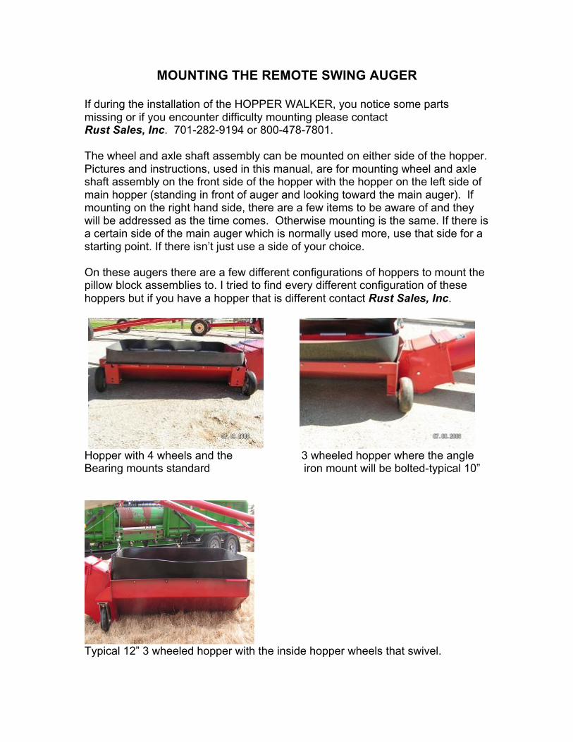
MOUNTING THE REMOTE SWING AUGER If during the installation of the HOPPER WALKER, you notice some parts missing or if you encounter difficulty mounting please contact Rust Sales, Inc. 701-282-9194 or 800-478-7801. The wheel and axle shaft assembly can be mounted on either side of the hopper. Pictures and instructions, used in this manual, are for mounting wheel and axle shaft assembly on the front side of the hopper with the hopper on the left side of main hopper (standing in front of auger and looking toward the main auger). If mounting on the right hand side, there are a few items to be aware of and they will be addressed as the time comes. Otherwise mounting is the same. If there is a certain side of the main auger which is normally used more, use that side for a starting point. If there isn’t just use a side of your choice. On these augers there are a few different configurations of hoppers to mount the pillow block assemblies to. I tried to find every different configuration of these hoppers but if you have a hopper that is different contact Rust Sales, Inc.
Hopper with 4 wheels and the 3 wheeled hopper where the angle Bearing mounts standard iron mount will be bolted-typical 10”
Typical 12” 3 wheeled hopper with the inside hopper wheels that swivel.
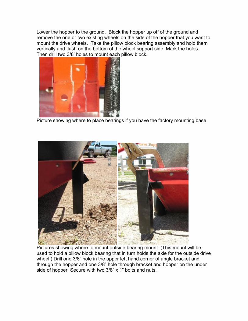
Lower the hopper to the ground. Block the hopper up off of the ground and remove the one or two existing wheels on the side of the hopper that you want to mount the drive wheels. Take the pillow block bearing assembly and hold them vertically and flush on the bottom of the wheel support side. Mark the holes. Then drill two 3/8’ holes to mount each pillow block.
Picture showing where to place bearings if you have the factory mounting base.
Pictures showing where to mount outside bearing mount. (This mount will be used to hold a pillow block bearing that in turn holds the axle for the outside drive wheel.) Drill one 3/8” hole in the upper left hand corner of angle bracket and through the hopper and one 3/8” hole through bracket and hopper on the under side of hopper. Secure with two 3/8” x 1” bolts and nuts.
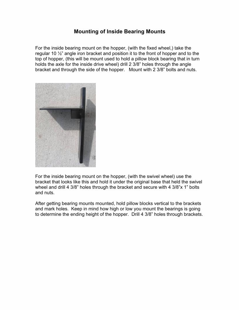
Mounting of Inside Bearing Mounts For the inside bearing mount on the hopper, (with the fixed wheel,) take the regular 10 ½” angle iron bracket and position it to the front of hopper and to the top of hopper, (this will be mount used to hold a pillow block bearing that in turn holds the axle for the inside drive wheel) drill 2 3/8” holes through the angle bracket and through the side of the hopper. Mount with 2 3/8” bolts and nuts.
For the inside bearing mount on the hopper, (with the swivel wheel) use the bracket that looks like this and hold it under the original base that held the swivel wheel and drill 4 3/8” holes through the bracket and secure with 4 3/8”x 1” bolts and nuts. After getting bearing mounts mounted, hold pillow blocks vertical to the brackets and mark holes. Keep in mind how high or low you mount the bearings is going to determine the ending height of the hopper. Drill 4 3/8” holes through brackets.
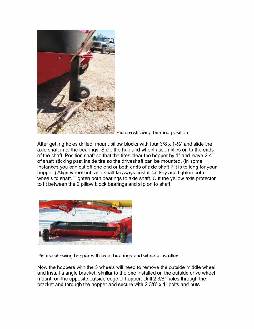
Picture showing bearing position After getting holes drilled, mount pillow blocks with four 3/8 x 1-½” and slide the axle shaft in to the bearings. Slide the hub and wheel assemblies on to the ends of the shaft. Position shaft so that the tires clear the hopper by 1” and leave 2-4” of shaft sticking past inside tire so the driveshaft can be mounted. (in some instances you can cut off one end or both ends of axle shaft if it is to long for your hopper.) Align wheel hub and shaft keyways, install ¼” key and tighten both wheels to shaft. Tighten both bearings to axle shaft. Cut the yellow axle protector to fit between the 2 pillow block bearings and slip on to shaft
. Picture showing hopper with axle, bearings and wheels installed. Now the hoppers with the 3 wheels will need to remove the outside middle wheel and install a angle bracket, similar to the one installed on the outside drive wheel mount, on the opposite outside edge of hopper. Drill 2 3/8” holes through the bracket and through the hopper and secure with 2 3/8” x 1” bolts and nuts.
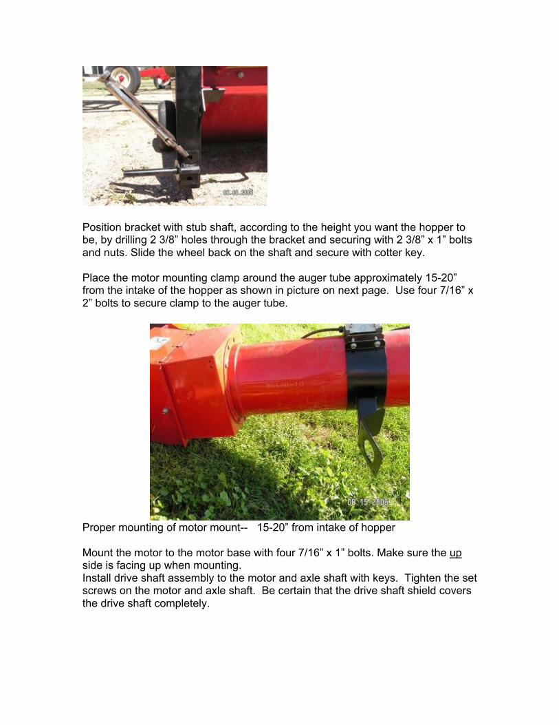
Position bracket with stub shaft, according to the height you want the hopper to be, by drilling 2 3/8” holes through the bracket and securing with 2 3/8” x 1” bolts and nuts. Slide the wheel back on the shaft and secure with cotter key. Place the motor mounting clamp around the auger tube approximately 15-20” from the intake of the hopper as shown in picture on next page. Use four 7/16” x 2” bolts to secure clamp to the auger tube.
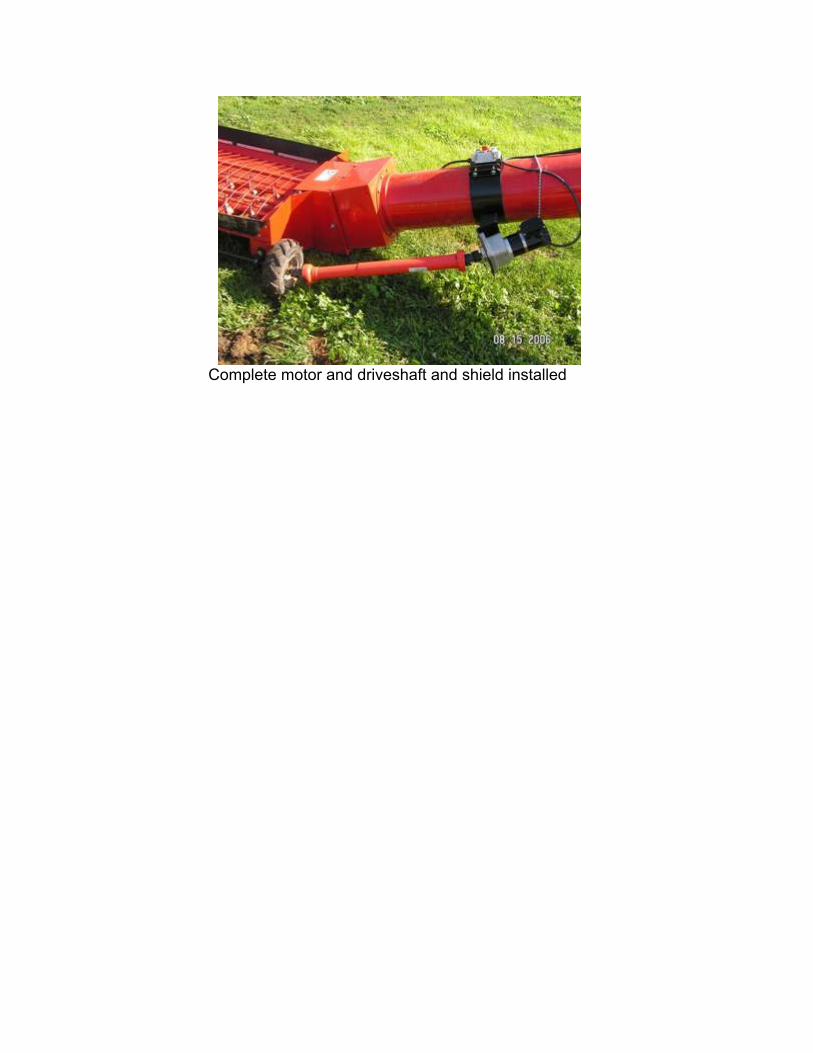
Proper mounting of motor mount-- 15-20” from intake of hopper Mount the motor to the motor base with four 7/16” x 1” bolts. Make sure the up side is facing up when mounting. Install drive shaft assembly to the motor and axle shaft with keys. Tighten the set screws on the motor and axle shaft. Be certain that the drive shaft shield covers the drive shaft completely.
Complete motor and driveshaft and shield installed
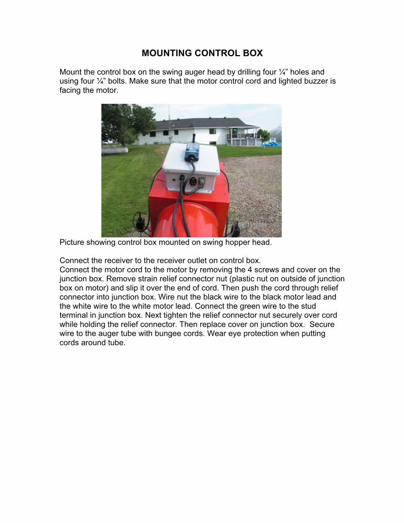
MOUNTING CONTROL BOX Mount the control box on the swing auger head by drilling four ¼” holes and using four ¼” bolts. Make sure that the motor control cord and lighted buzzer is facing the motor.
Picture showing control box mounted on swing hopper head. Connect the receiver to the receiver outlet on control box. Connect the motor cord to the motor by removing the 4 screws and cover on the junction box. Remove strain relief connector nut (plastic nut on outside of junction box on motor) and slip it over the end of cord. Then push the cord through relief connector into junction box. Wire nut the black wire to the black motor lead and the white wire to the white motor lead. Connect the green wire to the stud terminal in junction box. Next tighten the relief connector nut securely over cord while holding the relief connector. Then replace cover on junction box. Secure wire to the auger tube with bungee cords. Wear eye protection when putting cords around tube.
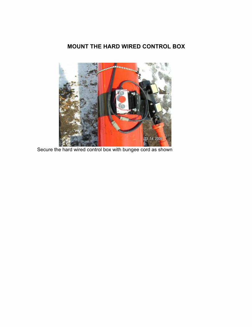
MOUNT THE HARD WIRED CONTROL BOX
Secure the hard wired control box with bungee cord as shown
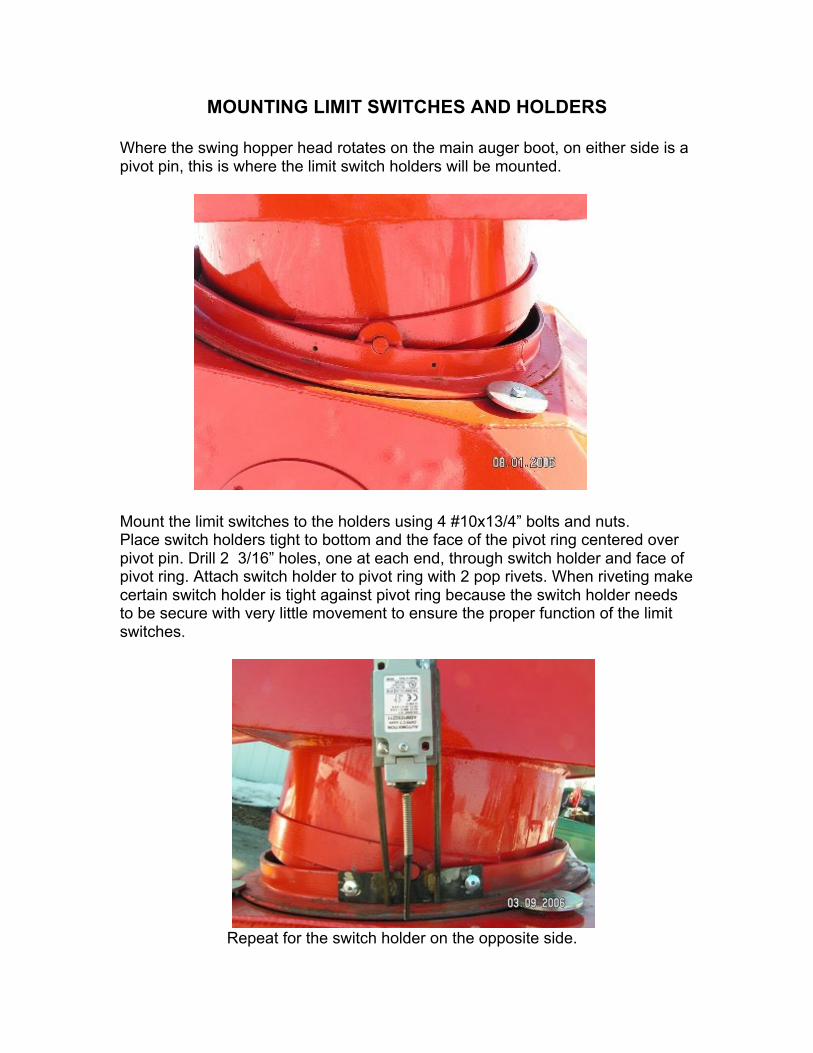
MOUNTING LIMIT SWITCHES AND HOLDERS Where the swing hopper head rotates on the main auger boot, on either side is a pivot pin, this is where the limit switch holders will be mounted.
Mount the limit switches to the holders using 4 #10x13/4” bolts and nuts. Place switch holders tight to bottom and the face of the pivot ring centered over pivot pin. Drill 2 3/16” holes, one at each end, through switch holder and face of pivot ring. Attach switch holder to pivot ring with 2 pop rivets. When riveting make certain switch holder is tight against pivot ring because the switch holder needs to be secure with very little movement to ensure the proper function of the limit switches.
Repeat for the switch holder on the opposite side.
MOUNTING LIMIT SWITCH STOP BRACKETS AND LIMIT SWITCH STOPS
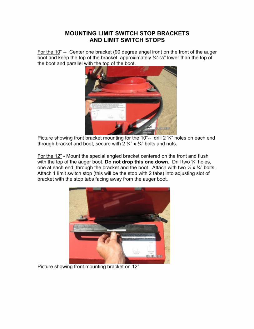
For the 10“ -- Center one bracket (90 degree angel iron) on the front of the auger boot and keep the top of the bracket approximately ¼“-½” lower than the top of the boot and parallel with the top of the boot.
Picture showing front bracket mounting for the 10”-- drill 2 ¼” holes on each end through bracket and boot, secure with 2 ¼” x ¾” bolts and nuts. For the 12” - Mount the special angled bracket centered on the front and flush with the top of the auger boot. Do not drop this one down. Drill two ¼’ holes, one at each end, through the bracket and the boot. Attach with two ¼ x ¾” bolts. Attach 1 limit switch stop (this will be the stop with 2 tabs) into adjusting slot of bracket with the stop tabs facing away from the auger boot.
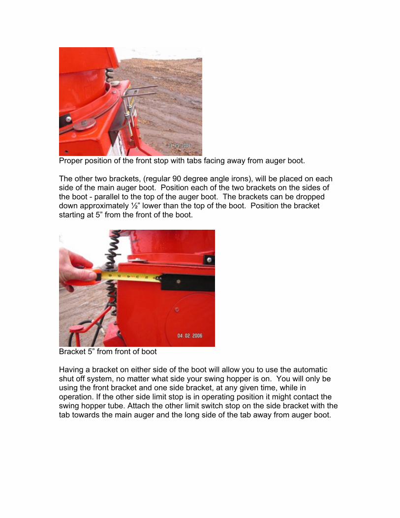
Picture showing front mounting bracket on 12”
Proper position of the front stop with tabs facing away from auger boot. The other two brackets, (regular 90 degree angle irons), will be placed on each side of the main auger boot. Position each of the two brackets on the sides of the boot - parallel to the top of the auger boot. The brackets can be dropped down approximately ½” lower than the top of the boot. Position the bracket starting at 5” from the front of the boot.
Bracket 5” from front of boot Having a bracket on either side of the boot will allow you to use the automatic shut off system, no matter what side your swing hopper is on. You will only be using the front bracket and one side bracket, at any given time, while in operation. If the other side limit stop is in operating position it might contact the swing hopper tube. Attach the other limit switch stop on the side bracket with the tab towards the main auger and the long side of the tab away from auger boot.
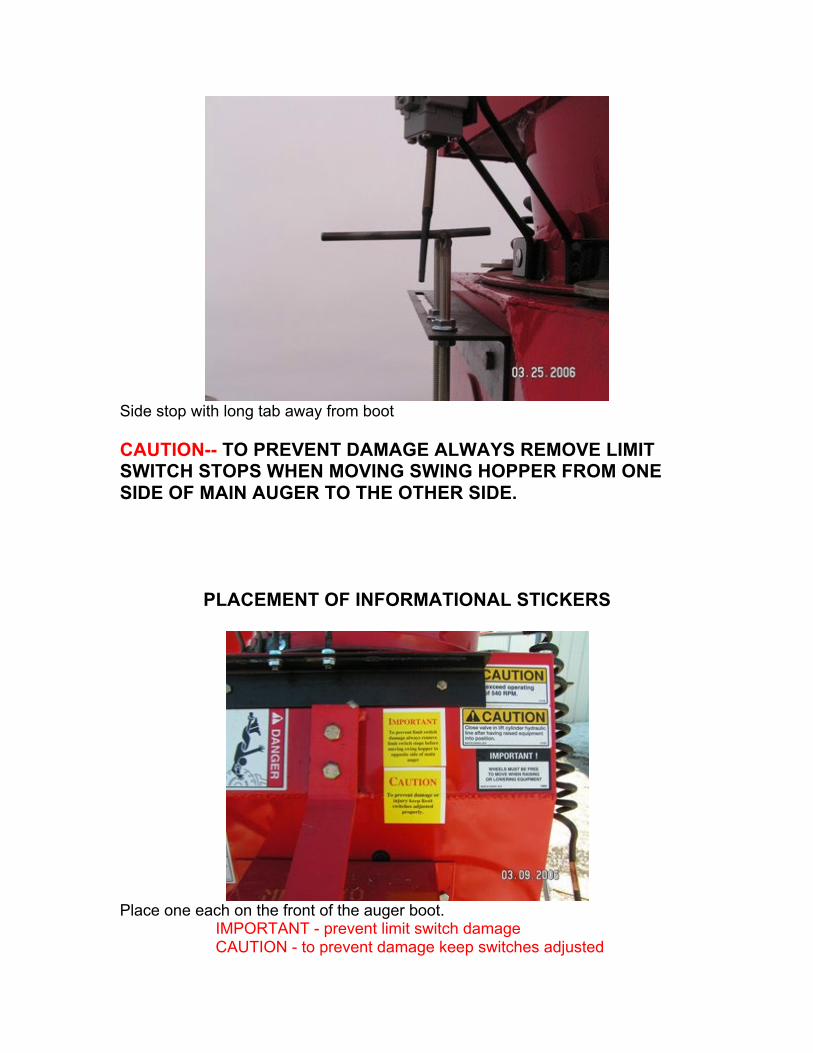
Side stop with long tab away from boot CAUTION-- TO PREVENT DAMAGE ALWAYS REMOVE LIMIT SWITCH STOPS WHEN MOVING SWING HOPPER FROM ONE SIDE OF MAIN AUGER TO THE OTHER SIDE.
PLACEMENT OF INFORMATIONAL STICKERS
Place one each on the front of the auger boot.
IMPORTANT - prevent limit switch damage CAUTION - to prevent damage keep switches adjusted
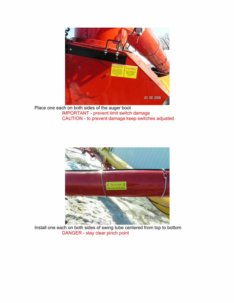
Place one each on both sides of the auger boot IMPORTANT - prevent limit switch damage CAUTION - to prevent damage keep switches adjusted
Install one each on both sides of swing tube centered from top to bottom
DANGER - stay clear pinch point
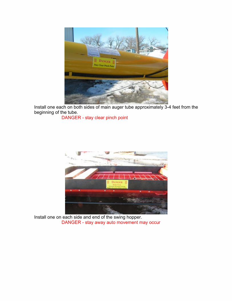
Install one each on both sides of main auger tube approximately 3-4 feet from the beginning of the tube.
DANGER - stay clear pinch point
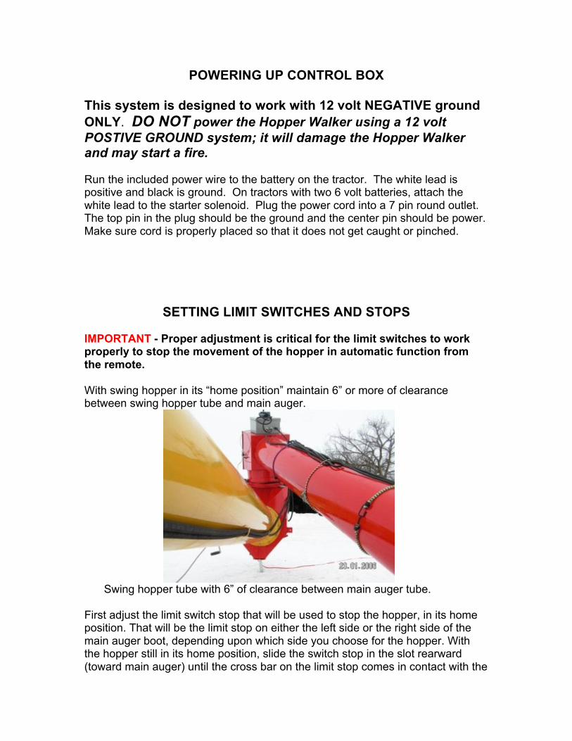
Install one on each side and end of the swing hopper.
DANGER - stay away auto movement may occur
POWERING UP CONTROL BOX
This system is designed to work with 12 volt NEGATIVE ground ONLY. DO NOT power the Hopper Walker using a 12 volt POSTIVE GROUND system; it will damage the Hopper Walker and may start a fire. Run the included power wire to the battery on the tractor. The white lead is positive and black is ground. On tractors with two 6 volt batteries, attach the white lead to the starter solenoid. Plug the power cord into a 7 pin round outlet. The top pin in the plug should be the ground and the center pin should be power. Make sure cord is properly placed so that it does not get caught or pinched.
SETTING LIMIT SWITCHES AND STOPS
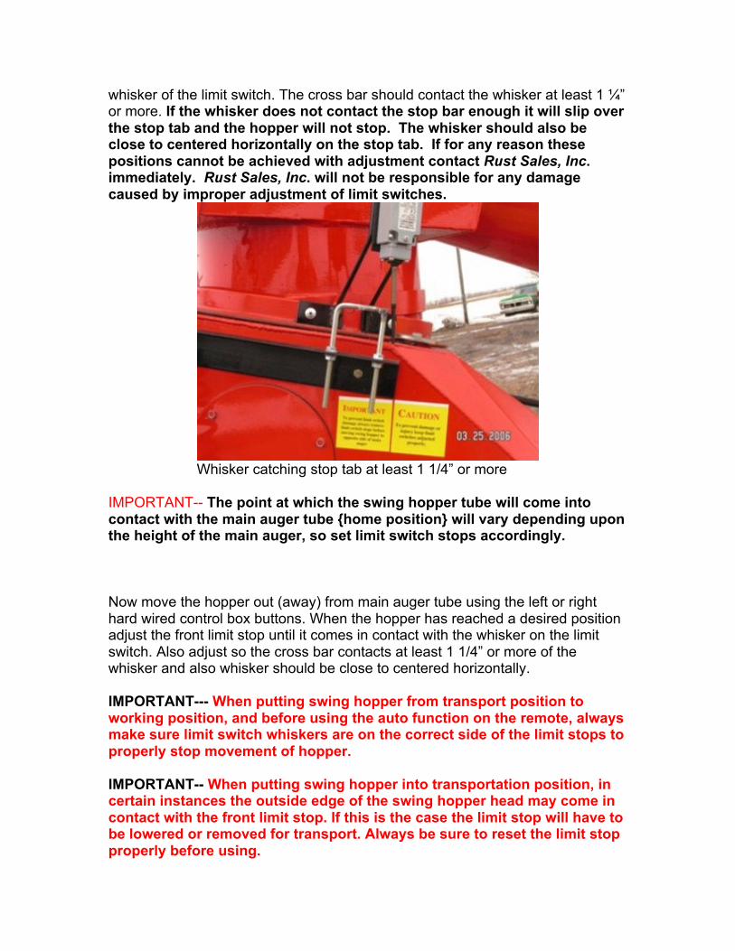
IMPORTANT - Proper adjustment is critical for the limit switches to work properly to stop the movement of the hopper in automatic function from the remote. With swing hopper in its “home position” maintain 6” or more of clearance between swing hopper tube and main auger.
Swing hopper tube with 6” of clearance between main auger tube. First adjust the limit switch stop that will be used to stop the hopper, in its home position. That will be the limit stop on either the left side or the right side of the main auger boot, depending upon which side you choose for the hopper. With the hopper still in its home position, slide the switch stop in the slot rearward (toward main auger) until the cross bar on the limit stop comes in contact with the
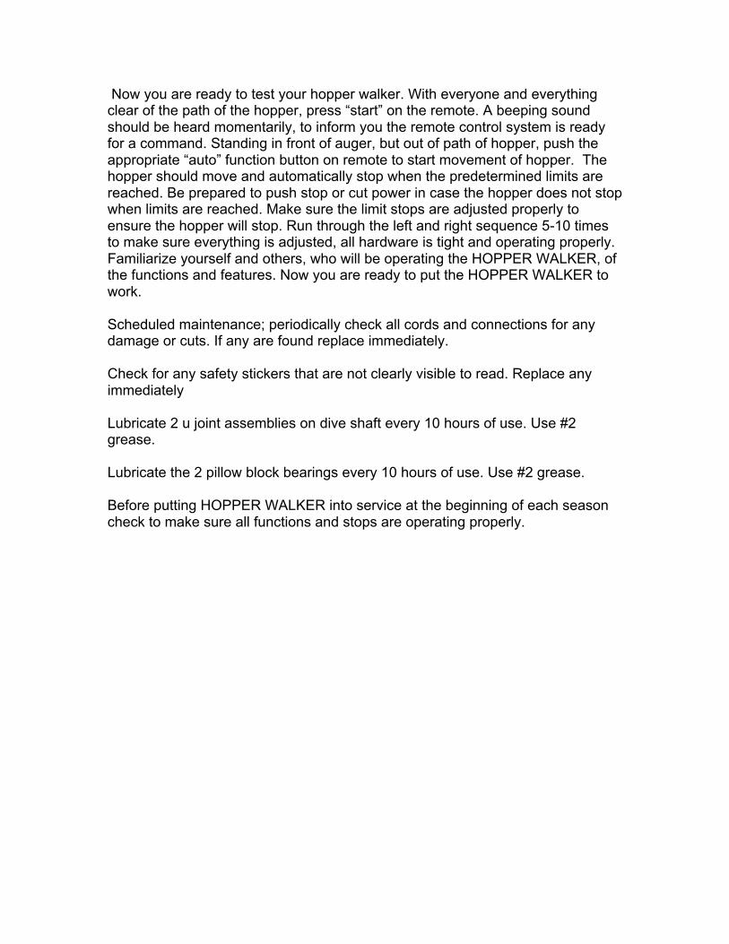
whisker of the limit switch. The cross bar should contact the whisker at least 1 ¼” or more. If the whisker does not contact the stop bar enough it will slip over the stop tab and the hopper will not stop. The whisker should also be close to centered horizontally on the stop tab. If for any reason these positions cannot be achieved with adjustment contact Rust Sales, Inc. immediately. Rust Sales, Inc. will not be responsible for any damage caused by improper adjustment of limit switches.
Whisker catching stop tab at least 1 1/4” or more IMPORTANT-- The point at which the swing hopper tube will come into contact with the main auger tube {home position} will vary depending upon the height of the main auger, so set limit switch stops accordingly. Now move the hopper out (away) from main auger tube using the left or right hard wired control box buttons. When the hopper has reached a desired position adjust the front limit stop until it comes in contact with the whisker on the limit switch. Also adjust so the cross bar contacts at least 1 1/4” or more of the whisker and also whisker should be close to centered horizontally. IMPORTANT--- When putting swing hopper from transport position to working position, and before using the auto function on the remote, always make sure limit switch whiskers are on the correct side of the limit stops to properly stop movement of hopper. IMPORTANT-- When putting swing hopper into transportation position, in certain instances the outside edge of the swing hopper head may come in contact with the front limit stop. If this is the case the limit stop will have to be lowered or removed for transport. Always be sure to reset the limit stop properly before using.
Now you are ready to test your hopper walker. With everyone and everything clear of the path of the hopper, press “start” on the remote. A beeping sound should be heard momentarily, to inform you the remote control system is ready for a command. Standing in front of auger, but out of path of hopper, push the appropriate “auto” function button on remote to start movement of hopper. The hopper should move and automatically stop when the predetermined limits are reached. Be prepared to push stop or cut power in case the hopper does not stop when limits are reached. Make sure the limit stops are adjusted properly to ensure the hopper will stop. Run through the left and right sequence 5-10 times to make sure everything is adjusted, all hardware is tight and operating properly. Familiarize yourself and others, who will be operating the HOPPER WALKER, of the functions and features. Now you are ready to put the HOPPER WALKER to work. Scheduled maintenance; periodically check all cords and connections for any damage or cuts. If any are found replace immediately. Check for any safety stickers that are not clearly visible to read. Replace any immediately Lubricate 2 u joint assemblies on dive shaft every 10 hours of use. Use #2 grease. Lubricate the 2 pillow block bearings every 10 hours of use. Use #2 grease. Before putting HOPPER WALKER into service at the beginning of each season check to make sure all functions and stops are operating properly.