100 WASHING MACHINE SERVICE MANUAL READ THIS MANUAL CAREFULLY TO DIAGNOSE PROBLEMS CORRECTLY BEFORE SERVICING THE UNIT. MODEL : WM2411HW/WM2011H*/WM1811CW WM2432HW/WM2032H*/WM1832CW WM0532HW/WD-10210BD/WD-12210(5)BD WM2444H*M/WM2442H*/WM2042CW WM0642H* CAUTION Website:http://www.LGEservice.com E-mail:http://www.LGEservice.com/techsup.html !
Transcript
100
WASHING MACHINESERVICE MANUAL
READ THIS MANUAL CAREFULLY TO DIAGNOSE PROBLEMS CORRECTLY BEFORE SERVICING THE UNIT.
MODEL : WM2411HW/WM2011H*/WM1811CWWM2432HW/WM2032H*/WM1832CWWM0532HW/WD-10210BD/WD-12210(5)BDWM2444H*M/WM2442H*/WM2042CW WM0642H*
OPERATIONAL WATER PRESSURE 4.5-145 psi (30-1000 kPa)
CONTROL TYPE Electronic
WASH CAPACITY 3.32 cu.ft (3.83 cu.ft.IEC)
DIMENSIONS 27”(W) X 29-1/2”(D) X 44”(H), 49-4/5”(D, door open)
DELAY WASH up to 12 hours up to 9 hours
DOOR SWITCH TYPE PTC + Solenoid
WATER LEVEL 10 steps (by sensor)
LAUNDRY LOAD SENSING Incorporated
ERROR DIAGNOSIS Incorporated
AUTO POWER OFF Incorporated
CHILD LOCK Incorporated
RLM ENABLE Incorporated -
ELECTRIC
POWER
CONSUMPTION
REVOLUTION SPEED
5
2. FEATURES & TECHNICAL EXPLANATION
2-1.FEATURES
Direct Drive SystemThe advanced Brushless DC motor directly drives the drum without belt and pulley.
Tilted Drum and Extra Large Door OpeningThe tilted drum and extra large door opening make it possible to load and unload easily.
Water Circulation Spray detergent solution and water onto the load repeatedly. Clothes are soaked more quickly and thoroughly during the wash cycle. Detergent suds are eliminated more easily by the water shower during rinse cycle. The water circulation system uses both water and detergent more efficiently.
RollerJets The washing ball enhances wash performance and reduces damage to clothing. The jets spray and help tumble clothes to enhancewashing performance while maintaining fabric care.
Built-in Heater The internal heater automatically heats the water to the optimumtemperature on selected cycles.
Child LockThe Child lock feature prevents children from pressing any buttons to change the settings during operation.
Using the RLM (Remote Laundry Monitor) The RLM monitors status of your washer and/or dryer. You can plug thedisplay unit into any power outlet in your home. The RLM Display Unit can be purchased separately for this washer.
6
2-2.FUZZY LOGIC WASHING TIME OPTIMIZATIONTo get the best washing performance, optimal time is determined by the water temperature,
the selected washing temperature, and the size of the load.
2-3.WATER LEVEL CONTROLThis model incorporates a pressure sensor which can sense the water level in the tub.
The water supply is stopped when the water level reaches the preset level, the washing
program then proceeds.
Spinning does not proceed until the water in the tub drains to a certain level.
2-4.DOOR CONTROLThe door can be opened by pulling the door handle whenever washer is not in operation.
When the cycle is completed, the DOOR LOCKED light will turn off.
If a power failure has occurred while in operation, the door will lock for 5 minutes.
Clicking sounds can be heard when the door is locked / unlocked.
FUZZYLOGIC
loadsize
selectedwashing
temperature
watertemperature
washing time
rinsing time
spin rhythm, time
the bestwashingperformance
SENSING PROCESSING DETERMINATION EFFECT
7
3. PARTS IDENTIFICATION
ACCESSORIES
(PLC Modem)
• If the supply cord isdamaged, it must bereplaced by themanufacturer or itsauthorized servicetechnician in order toavoid a hazard.
8
Before servicing, ask the customer what the trouble is.Check the setup (power supply is 120V AC, remove the transit bolts....).Check with the troubleshooting guide.Plan your service method by referring to the disassembly instructions.Service the unit.After servicing, operate the appliance to see whether it functions correctly.
STANDARD INSTALLATIONThe appliance should be installed as follows:
REMOVE THE TRANSIT INSTALL THE APPLIANCE ADJUST THE
BOLTS ON A FLAT AND FIRM SURFACE LEVELING
Remove the transit bolts Turn the leveling feet to adjust (4 EA: ) with the supplied wrench. the appliance horizontally.
Keep the transit bolts and
spanner for future use.
Insert the 4 caps
(provided) into the hole.
The appliance goes up by
rotating the feet clockwise.
The appliance come down by
rotating the feet counterclockwise.
4. INSTALLATION
9
HOW TO CONNECT THE INLET HOSE
Verify that the rubber washer is inside of the
valve connector.
Connect the inlet hose firmly to prevent leaks.
CONNECT THE DRAIN HOSE
CONNECT POWER PLUG
The end of the drain hose should be placed less than 96” from the floor.
Connect the power plug to the wall outlet. Avoid connecting several electric devices, asdoing so may cause a fire.
Make sure that the hose is not twisted. Avoid submerging the end of the hose.
10
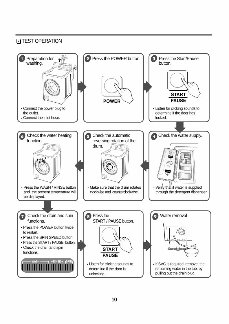
TEST OPERATION
Connect the power plug tothe outlet.Connect the inlet hose.
Press the POWER button twiceto restart.Press the SPIN SPEED button.Press the START / PAUSE button.Check the drain and spinfunctions.
Listen for clicking sounds todetermine if the door isunlocking.
Listen for clicking sounds todetermine if the door haslocked.
If SVC is required, remove theremaining water in the tub, bypulling out the drain plug.
Preparation for Press the POWER button. Press the Start/Pausewashing. button.
Press the WASH / RINSE button Make sure that the drum rotates Verify that if water is suppliedand the present temperature will clockwise and counterclockwise. through the detergent dispenser.be displayed.
Check the water heating Check the automatic Check the water supply.function. reversing rotation of the
drum.
Check the drain and spin Press the Water removal functions. START / PAUSE button.
11
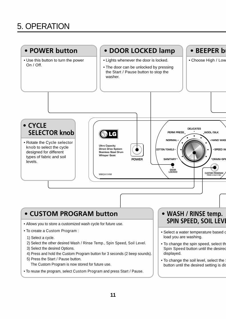
5. OPERATION
• Use this button to turn the power On / Off.
• Rotate the Cycle selectorknob to select the cycledesigned for differenttypes of fabric and soillevels.
• Allows you to store a customized wash cycle for future use.
• To create a Custom Program :
1) Select a cycle.2) Select the other desired Wash / Rinse Temp., Spin Speed, Soil Level.3) Select the desired Options.4) Press and hold the Custom Program button for 3 seconds (2 beep sounds).5) Press the Start / Pause button.
The Custom Program is now stored for future use.
• To reuse the program, select Custom Program and press Start / Pause.
• Lights whenever the door is locked.
• The door can be unlocked by pressingthe Start / Pause button to stop thewasher.
• Choose High / Low
• Select a water temperature based oload you are washing.
• To change the spin speed, select thSpin Speed button until the desireddisplayed.
• To change the soil level, select the Sbutton until the desired setting is dis
12
• Use this option to preventunwanted use of the washer.Press and hold Quick Cycle andDelay Wash button for 3 secondsto lock / unlock control.
• When Child lock is set, “ ” blinksand all buttons are disabled butthe Power button. You can thereby lock the washer while it is operating.
• Prewash : Use this option for loads that need pretreatment.It adds 16 minutes prewash and drain.
• Stain Cycle : Adds time to the wash and rinse cycles forbetter stain removal. Automatically provides arinse.
• Quick Cycle : The Quick cycle offers a quick cycle time.
• Extra Rinse : This option provides an additional rinse cycle.
• Rinse+Spin : Use this option to rinse and then spin.
• Delay Wash : Allows the start of any cycle to be delayed for1~19(12, 9) hours.
• Use this button to Start /Stop the washer.
/ Off.
on the type of
e setting is
Soil Levelsplayed.
• These lights show elapsed time of theselected cycle.
• This display shows :
a) the estimated time remaining in the cycle whenoperating.
7-1. BEFORE PERFORMING SERVICEBe careful of electric shock when disconnecting parts for while troubleshooting.
The voltage of each terminal is 120V AC and DC when the unit is plugged in.
7-2. QC TEST MODE.The washer must be empty and the controls must be in the off state.
¤¤ÁPress the SPIN SPEED and SOIL LEVEL buttons simultaneously.
¤¤ŁŁPress the Power button, while the above condition. Then buzzer sound twice.
¤¤ØØIn order to advance to the next step of test mode, press the START / PAUSE button once.
7-3. HOW TO CHECK THE WATER LEVEL FREQUENCYPress the SPIN SPEED and SOIL LEVEL button simultaneously.
So, for example a display indicating 241 : a Water level frequency of 241 x.1 kHz= 24.1 kHz
The digits indicate the water level frequency ( x.1 kHz ).
Check Point Display Status
None Turns on all lamps and locks the door.
1 time Tumble clockwise. rpm (40~50)
2 times Low speed Spin. rpm
3 times High speed Spin. rpm
4 times Inlet valve for prewash turns on. Water level frequency (25~65)
5 times Inlet valve for main wash turns on. Water level frequency (25~65)
6 times Inlet valve for hot water turns on. Water level frequency (25~65)
7 times Inlet valve for softener turns on. Water level frequency (25~65)
8 times Inlet valve for bleach turns on. Water level frequency (25~65)
9 times Tumble counterclockwise. rpm (40~50)
10 times Heater turns on for 3 sec. Water temperature
11 times Circulation pump turns on. Water level frequency (25~65)
12 times Drain pump turns on. Water level frequency (25~65)
13 times Power off and unlock the door. Turn off all lamps.
Number of times theStart/Pause button is pressed
WM2411HW WM2011HS / WM2011HW WM1811CW
WM2432HWWD-12210(5)BD
WM2032HS / WM2032HWWM0532HW / WD-10210BD
WM1832CW
20
7-4. ERROR DISPLAY
If you press the START/PAUSE button when an error is displayed, any error except willdisappear and the machine will go into the pause status.In case of if the error is not resolved within 20 sec., or the in case of other errors,if the error is not resolved within 4 min., power will be turned off automatically and the error code willblink. But in the case of , power will not be turned off.
ERROR SYMPTOM CAUSE
WATER INLETERROR
• Correct water level (2 level) is not reached within 8 minutesafter water is supplied or it does not reach the preset waterlevel within 25 minutes.
• The load is too small.• The appliance is tilted.• Laundry is gathered to one side.• Non distributable things are put into the drum.
1
2 IMBALANCEERROR
• Not fully drained within 10 minutes.3 DRAINERROR
• Water is overflowing (over 8 level).¡ If is displayed, the drain pump will operate to
the drain water automatically.4 OVER FLOW
ERROR
• The SENSOR SWITCH ASSEMBLY is out of order.5PRESSURE
SENSOR ERROR
• Door not all the way closed.• Loose electrical connections at Door switch and
PWB Assembly.• The DOOR SWITCH ASSEMBLY is out of order.
6 DOOR OPENERROR
• The THERMISTOR is out order.7 HEATINGERROR
21
ERROR SYMPTOM CAUSE
OVERCURRENT
ERROR
• MAIN PWB ASSEMBLY is out of order.
• Winding in the STATOR ASSEMBLY is short-circuited.
• The connector (3-pin, male, white) in the MOTORHARNESS is not connected to the connector (3-pin, female, white) of STATOR ASSEMBLY.
• The electric contact between the connectors (3-pin, male, white) in the MOTOR HARNESS and 4-pin, female, white connector in the MAIN PWBASSEMBLY is bad or unstable.
• The MOTOR HARNESS between the STATORASSEMBLY and MAIN PWB ASSEMBLY is cut (opencircuited).
• The hall sensor is out of order/defective.
8
9LOCKEDMOTORERROR
• Loose Ball Sensor Connector.• Ball Sensor is out of order.
¡ Displayed only when the START / PAUSE button is firstpressed in the QC Test Mode.
10 BALL SENSORERROR
• The washer experienced a power failure.12 POWERFAILURE
• EEPROM is out of order.¡ Displayed only when the START / PAUSE button is first
pressed in the QC Test Mode.11 EEPROM
ERROR
22
8-1.DIAGNOSIS AND SOLUTION FOR ABNORMAL OPERATION
8. ERROR DIAGNOSIS AND CHECK LIST
SYMPTOM GUIDE FOR SERVICE CALL
No power
Water inlet trouble
YES
YES
YES
NO
NO
YES
NO
NO
Is the power plug connected firmly to 120V AC outlet?
Power failure? or Breaker opened?Is the outlet controlled by a switch?
Visit to service.
Is displayed?
Is the tap opened?
Is the tap frozen?
Is the water supply shut-off?
Is filter in the inlet valve clogged withforeign material?
Visit to service.
Clean the filter ofinlet valve
23
SYMPTOM GUIDE FOR SERVICE CALL
Door error
Drain trouble
Was the load too large?
Visit to service.
Visit to service.
24
SYMPTOM GUIDE FOR SERVICE CALL
Suds overflow from theappliance.(In this condition, wash and spin do not operate normally)
No softening effect
YES
YES
YES
YES
Compartment forsoftener
Is a low-sudsing detergent used?
Is the proper amount of detergent used as recommended?
Recommend to reduce the amount of detergent.
Is softener put in the correct compartment ofthe dispenser?
Is the softener cap clogged?
Explain proper use of softener.
Clean the softener compartment
Visit to service.
LOW-SUDSING
This appliance has an automatic suds sensing function whichprevents overflow.When excessive suds are sensed, the suds removingimplementations such as drain, water input, pause will operate,without rotating the drum.
25
Connector
NO
YES
YES
YES
YES
NO
NO
NO
NO
YES
Is the supplied voltage 120V AC?
Is the voltage between the 2 FILTER ASSEMBLYconnectors 120V AC?
Is the LED(1) on?
Are the connectors(2) on the PWB loose?
Is wire of the DISPLAY PWB ASSEMBLY broken?
Replace DISPLAY PWB ASSEMBLY or repair wire.
Check the fuse or resetthe circuit breaker.
Replace the FILTERASSEMBLY (CIRC).
Replace MAIN PWBASSEMBLY.
Reconnect.
Replace the MAIN PWBASSEMBLY.
NO POWER
8-2.FAULT DIAGNOSIS AND TROUBLESHOOTING
1. Be careful of electric shock if disconnecting parts while troubleshooting.
2. First of all, check the connection of each electrical terminal with the wiring diagram.
3. If you replace the MAIN PWB ASSEMBLY, reinsert the connectors correctly.
CAUTION
26
NO
YES
NO
NO
YES
NO
YES
YES
NO
NO
YES
YES
YES
NO
NO
NO
YES
Is water supply shut-off?
Is the tap opened?
When you press both SPIN SPEED button andSOIL LEVEL button simultaneously, is the waterlevel frequency below 246?
Is the inlet valve filter clogged?
Is resistance between each terminal of INLETVALVE ASSEMBLY 0.8-1.2kΩ?
Verify the voltage of the inlet valve connector is
120V AC.
(Refer to 7-2 QC TEST MODE)
Is water supplied?
Are receptacles correctly connected to theterminals of the INLET VALVE ASSEMBLY?
Has detergent been put in the correct compartmentof the dispenser?
Is the detergent caked or hardened?
Open the tap.
Check the AIR CHAMBERand the tube (clogged).
Clean the filter.
Replace the INLET VALVEASSEMBLY.
Check electrical connection.Replace the MAIN PWBASSEMBLY.
Refer to NO WATER SUPPLY
Check the wiring.
Put the detergent in thecorrect place.
Clean the dispenser.
NO WATER SUPPLY
DETERGENT DOES NOT FLOW IN
27
ABNORMAL SOUND
SOFTENER / BLEACH DOES NOT FLOW IN
Secure the bolt.
Replace the STATORASSEMBLY or ROTORASSEMBLY.
Refer toNO WATER SUPPLY
Check the wiring on the dispenser.
Put it in the correctcompartment.
Clean the Cap andContainer.
Is the motor bolt loosened?
Is there friction noise coming from the motor?
Is water supplied?
Are the plugs correctly connected to the terminals ofthe INLET VALVE ASSEMBLY?
Is softener / bleach put in the correct compartment ofthe drawer?
Is the softener / bleach cap clogged?
28
NO
YES
YES
YES
YES
NO
NO
NO
NO
YES
YES
NO
Replace theSENSOR SWITCHASSEMBLY.
Replace the MAIN PWBASSEMBLY.
Repair the DRAIN HOSE ASSEMBLY.
Remove foreign material.
Reconnect or repair theconnector
Replace the DRAINPUMP ASSEMBLY.
Replace the MAIN PWB ASSEMBLY.
When pressing SPIN SPEED and SOIL LEVEL at thesame time after draining, is the water level frequency255? When pressing SPIN SPEED and SOIL LEVEL buttonsat the same time while wash, is the water levelfrequency between 230 - 243 ?
Check the voltage between two pins while pressingthe POWER button. Is the voltage 120V AC?
Is the drain hose twisted or frozen?
Is the impeller of the drain pump clogged?
Is the connector disconnected, disassembled?
Is the coil of the drain pump too high or low?(resistance of coil is 10-20Ω)
When checking voltage between connectors during
spin, is the voltage 120V AC as in the figure?
HEATING WITHOUT WATER
DRAIN MALFUNCTIONING
29
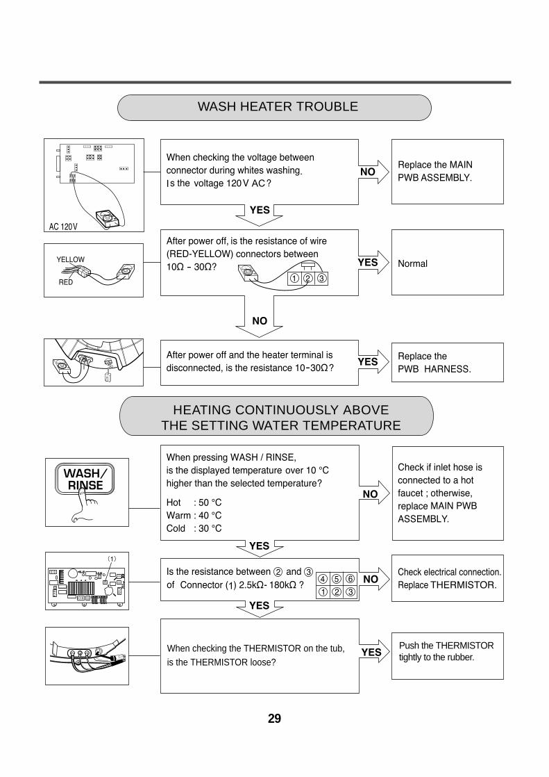
Push the THERMISTORtightly to the rubber.
When checking the THERMISTOR on the tub, is the THERMISTOR loose?
HEATING CONTINUOUSLY ABOVE THE SETTING WATER TEMPERATURE
WASH HEATER TROUBLE
30
YES
YES
YES
YESYES
NO
NO
NO
NO
NO
Hose
Connector
(White)
Connector
Connector
Hose
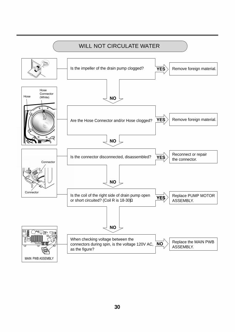
WILL NOT CIRCULATE WATER
Is the impeller of the drain pump clogged?
Are the Hose Connector and/or Hose clogged?
Is the connector disconnected, disassembled?
Is the coil of the right side of drain pump openor short circuited? (Coil R is 18-30Ω)
When checking voltage between the connectors during spin, is the voltage 120V AC,as the figure?
Remove foreign material.
Remove foreign material.
Reconnect or repair the connector.
Replace PUMP MOTORASSEMBLY.
Replace the MAIN PWBASSEMBLY.
31
SPIN TROUBLE
Check the SENSOR SWITCHASSEMBLY or HOSE (Pressure). If the problem is on the SENSORSWITCH ASSEMBLY or theHOSE, replace the SENSORSWITCH ASSEMBLY or theHOSE.
Normal
Correct the connection.
Replace the STATORASSEMBLY
Check during spin if the frequency of the waterlevel is 248 or more.
Press the START / PAUSE button 2 times in QCTest mode, is the drum spinning at low speed?
Is it disconnected, or disassembled?[Red:3pin (1), NA:4pin (2)]
Check the motor connector, Is the resistance ofthe terminal the same as the figure?MOTOR TERMINAL
Resistance of terminal: ¥L-¥M / ¥M-¥N / ¥N-¥L About 5Ω 15Ω
Replace the MAIN PWB ASSEMBLY
Does the spring of Latch Hook actuate?
Is there clicking sound once or twice when theSTART/PAUSE button is pressed to start the cycle?
Is DOOR SWITCH ASSEMBLY broken?
Replace Door Assembly.
Check the DOOR SWITCHASSEMBLY Connector andMAIN PWB ASSEMBLY(Red 4 pin and white 4 pinconnector (1)).
Replace the DOORSWITCH ASSEMBLY.
¥N ¥M ¥L
32
1. Unscrew 7 screws on the Rear Frame.
2. Disassemble the Rear Frame.
3. Pull the Control panel forward.
4. Disconnect connectors.
5. Unscrew 5 screws.
6. Disassemble the controller assembly.
1. Open the Lid.
2. Unscrew 4 screws.
3. Disassemble the Lid Assembly.
4. Pull down the Dispenser by pushing hooks.
5. Put a hand into the dispenser hole and hold the top plate.
6. Push backward using an opener and lift the top plate.
9. DISASSEMBLY INSTRUCTIONSƒR Disassemble and repair the unit only after pulling out power plug from the outlet.
LID
¡ Do first left side (¥L).
33
1. Disassemble the 5 hose clamps.
2. Release the 5 hoses.
3. Unscrew the nut at the lowerpart of the dispenser.


![WASHING MACHINE SERVICE MANUAL - Dryerdryernotheating.net/wp-content/uploads/2013/07/WM3431-LG-Compact... · WASHING MACHINE SERVICE MANUAL ... [For CANADA] ... The washer must be](https://static.documents.pub/doc/80x56/5ae3a1717f8b9ae74a8dfbe1/washing-machine-service-manual-machine-service-manual-for-canada-the.jpg)


