Publications Transmittal Transmittal Number Date PT 17-003 March 2017 Publication Distribution To: Hydraulics Manual holders Publication Title Publication Number Hydraulics Manual – March 2017 M 23-03.05 Originating Organization WSDOT Development Division – Design Office, Utilities, Railroads, and Agreements Section REMARKS AND INSTRUCTIONS Remove/Insert instructions for those who maintain a printed manual: CHAPTER REMOVE PAGES INSERT PAGES Title Page and Contents All 1-6 Chapter 10 N/A 10-i – 10-38 About revision marks: • Chapter 10 of this manual supersedes Instructional Letter IL 4076 Large Woody Material Structures Used in Water Bodies, dated March 3, 2016. • A new date appears in the footer of each division/appendix page that has changes. • Revision marks (underlines/sidebars) are used where new text has been added. They are a convenience to show designers what has changed. • When a chapter is new or completely rewritten, no revision marks are applied. Publications Services: To access the latest Utilities Accommodation Policy revision package or separate sections, or to get the latest information on individual WSDOT publications, go to the Publications Services website: www.wsdot.wa.gov/publications/manuals/ HQ Design Office Signature Phone Number:
Transcript
Publications Transmittal
Transmittal Number Date PT 17-003 March 2017
Publication Distribution To: Hydraulics Manual holders
Publication Title Publication Number Hydraulics Manual – March 2017 M 23-03.05
Originating Organization WSDOT Development Division – Design Office, Utilities, Railroads, and Agreements Section
REMARKS AND INSTRUCTIONS
Remove/Insert instructions for those who maintain a printed manual:
CHAPTER REMOVE PAGES INSERT PAGES
Title Page and Contents All 1-6
Chapter 10 N/A 10-i – 10-38
About revision marks:
• Chapter 10 of this manual supersedes Instructional Letter IL 4076 Large WoodyMaterial Structures Used in Water Bodies, dated March 3, 2016.
• A new date appears in the footer of each division/appendix page that has changes.• Revision marks (underlines/sidebars) are used where new text has been added.
They are a convenience to show designers what has changed.• When a chapter is new or completely rewritten, no revision marks are applied.
Publications Services: To access the latest Utilities Accommodation Policy revision package or separate sections, or to get the latest information on individual WSDOT publications, go to the Publications Services website: www.wsdot.wa.gov/publications/manuals/
Environmental and Engineering ProgramsHydraulics Office
Americans with Disabilities Act (ADA) InformationMaterials can be made available in an alternate format by emailing the WSDOT Diversity/ADA Affairs Team at [email protected] or by calling toll free, 855-362-4ADA (4232). Persons who are deaf or hard of hearing may make a request by calling the Washington State Relay at 711.
Title VI Notice to the PublicIt is Washington State Department of Transportation (WSDOT) policy to ensure no person shall, on the grounds of race, color, national origin, or sex, as provided by Title VI of the Civil Rights Act of 1964, be excluded from participation in, be denied the benefits of, or be otherwise discriminated against under any of its federally funded programs and activities. Any person who believes his/her Title VI protection has been violated may file a complaint with WSDOT’s Office of Equal Opportunity (OEO). For Title VI complaint forms and advice, please contact OEO’s Title VI Coordinator at 360-705-7082.
To get the latest information on WSDOT publications, sign up for individual email updates at www.wsdot.wa.gov/publications/manuals.
Washington State Department of Transportation Hydraulics Office PO Box 47329 Olympia, WA 98504
Appendix A Typical LWM Structures ............................................................................................. 10-24
Appendix B Example LWM Design Process for Fish Passage Projects in Western Washington ... 10-30
Appendix C Typical LWM Installations for Stream Habitat Restoration ....................................... 10-36
Large Woody Materials Chapter 10
Page 10-ii WSDOT Hydraulics Manual M 23-03.05 March 2017
WSDOT Hydraulics Manual M 23-03.05 Page 10-1 March 2017
Chapter 10 Large Woody Materials
10-1 Introduction
Large woody material (LWM; also known in the literature as large woody debris) plays a critical role in many Washington streams through its influence on aquatic habitat and stream geomorphic processes. In many forested streams, wood is a fundamental driver of stream morphology. The quantity, size, and function of LWM in many of these stream systems has been altered through decades of timber harvesting, channel clearing, snag removal, and human alteration to stream channels and riparian zones, resulting in changes to stream channel form and function and the degradation of aquatic habitat. Restoration of instream LWM has therefore become a common restoration practice in WA State and throughout the Pacific Northwest. Placement of LWM can achieve a variety of physical and biological benefits to stream morphology and aquatic habitat. Large wood projects can be used to directly provide habitat cover, complexity, and natural levels of streambank stability, or may provide indirect benefits through their influence on pool development, sediment trapping, hydraulic roughness, and lateral channel dynamics.
Over the past century or more, the role of large wood in forming and maintaining stream habitat was not understood or was largely ignored. As settlement and development increased so did the removal of large wood and boulders from the state’s waterways. Past logging practices often removed trees to the edge of the stream, limiting future wood input to the stream. In many cases, streams were also cleared of wood to conveyance or fish migration. Over time, these and other activities resulted in depletion of habitat and channel forming structure in many streams. The removal of in-stream features often altered channel form, and how large wood, and sediment moved through the river system.
Since natural process have been eliminated, altered, or reduced in many areas, aquatic habitat restoration activities are an important method for reintroducing the necessary structure to stream channels that have been simplified due to past management practices and/or disturbance events. Aquatic habitat restoration activities are also a key to the success of the Washington’s implementation of the Salmon Recovery Planning Act. Aquatic habitat restoration activities are generally intended to address the watershed functions necessary to support healthy watersheds. This includes improving water quality, water quantity, channel complexity, floodplain interaction and the quality of riparian vegetation.
Frequently the best approach for habitat restoration is to mimic natural events and processes like a windstorm or landslide to guide placement of large woody material. This approach is most effective when the site has all the components for good habitat except for key pieces of woody materials to develop complex habitat.
Large Woody Materials Chapter 10
Page 10-2 WSDOT Hydraulics Manual M 23-03.05 March 2017
10-1.1 Purpose and Need
Aquatic habitat enhancement and restoration is becoming one of the most important environmental stewardship functions that WSDOT performs as it seeks to eliminate fish passage barriers at the many stream crossing of the state highway system (See Chapter 7 Fish Passage). In addition, the use of LWM for bank stability can be self-mitigating incorporated with hard revetments such as rock or concrete. WSDOT is increasingly being encouraged to incorporate LWM into bank stability and scour protection projects as sustainable habitat features.
The purpose of this guidance is to assist a designer in determining when LWM is appropriate so these features can be incorporated into design at project initiation rather than a redesign later in the design process as a response to comments from Tribes and other stakeholders or permitting agencies.
Because of the vulnerability and critical nature of highway infrastructure, the incorporation of LWM into fish passage and other projects, either as mitigation or as functional project elements, can be very challenging. Consequently, guidelines and procedures are needed to facilitate project designs. Public safety concerns for recreational river users pose additional challenges to the proper utilization of LWM.
Therefore, in order to ensure the safety, stability and functionality of LWM, WSDOT has developed these guidelines.
10-1.2 Guidance for LWM Placement in Emergencies
Generally, failure of a culvert system or a bank failure requires rapid response to stabilize and prevent additional damage to WSDOT facilities and to restore a safe travel corridor. In these cases, Regional maintenance staff likely need to act without the benefit of a reach assessment and a new engineering design to replace damaged facilities in light of the altered conditions. Maintenance staff are left to stabilize or restore or the site to the previous design specifications, in likely adverse environmental conditions. In as much as engineering judgement calls are needed during such situations, LWM placement during emergency repairs should be done only with the consultation of Headquarters Hydraulics or Hydrology staff. Additionally, LWM should be part of an emergency action only if it is deemed warranted.
Typically, emergency actions still require permits from the regulatory agencies and those permits may be conditioned with mitigation requirements. In these cases, LWM placement should be considered as an element of the mitigation for aquatic habitat impacts.
10-1.3 Design Oversight
The design of projects including LWM or Engineered Log Jams (ELJ) requires expertise in hydrology, hydraulics, and geomorphology. Because of the risks involved, all LWM placements in bank protection and stream restoration projects shall be designed under the supervision of the Hydraulics Section as described in Section 1-2 of this manual.
Chapter 10 Large Woody Materials
WSDOT Hydraulics Manual M 23-03.05 Page 10-3 March 2017
10-2 Design Process
Design of LWM structures and placements shall follow a geomorphic and ecological assessment of the watershed and a similar, more detailed assessment of the reach or site to be treated including an analysis of existing conditions and anticipated responses related to stability. The LWM design process is multistep process shown in Figure 10-1:
• a reach assessment is prepared to describe the geomorphic conditions the site, describe existing LWM in the system and determine that the use of LWM is suitable for the site conditions;
• a recreational water safety assessment is made to identify potential risks to the public and provide guidance to reduce potential risks;
• design based project objectives are identified; and
• design using general and project specific design criteria.
LWM Design Process
Figure 10-1
Large Woody Materials Chapter 10
Page 10-4 WSDOT Hydraulics Manual M 23-03.05 March 2017
10-3 Reach Assessments
A reach assessment is required for all WSDOT projects that incorporate LWM. A reach assessment is a scalable report depending on the unique conditions of each site that may range from a few paragraphs in the Basis of Design to a stand-alone report. The level of effort for the reach assessment will be determined by the Hydraulics Section. Reach assessments provide important geomorphic and habitat information that is critical to successful design of LWM projects.
Generally a reach assessment should follow the outline of the Integrated Streambank Protection Guidelines (ISPG; WDFW 2002) and characterize the conditions not only at the project site, but also a larger representative reach of channel and the watershed. In addition to identifying problems at a site and possible solutions, the reach assessment should include:
• a description of LWM found at the project site and within the representativereach: its likely sources and its functions in the channel;
• a discussion of the potential for LWM to be recruited: bank erosion, masswasting, windthrow, etc.; and
• a discussion of the ability of the water course to transport LWM to theproject site.
The National Transportation Research Board’s Effects of Debris on Bridge Pier Scour (NCHRP Report 653) and the FHWA’s Debris Control Structures: Evaluation and Countermeasures (HEC-9) provide thorough discussions of the recruitment and transport of LWM.
Finally, the reach assessment should determine if the use of LWM is suited to the conditions found at the project site. The following locations and conditions should be discouraged or avoided for LWM placement:
• Channels that have a history and/or a near-future likelihood of material torrentsand other mass wasting activity.
• Locations immediately above permanent culverts or bridges unless LWM isincorporated and designed as a protective project element.
• Locations within or under culverts or bridges.
• Confined channels where the valley floor width is less than twice the bankfullchannel width.
• Alluvial streams with a gradient of more than two percent.
• Non-alluvial streams with a gradient of more than four percent.
The USDA’s National Engineering Handbook (Technical Supplement 14J: Use of large woody material for habitat and bank protection) provides additional discussion of the limitations on the applicability of using LWM.
WSDOT Hydraulics Manual M 23-03.05 Page 10-5 March 2017
10-4 Recreational Waters Safety Assessment
Like a reach assessment, a recreational waters safety assessment is a scalable report depending on the unique conditions of each site that may range from a few paragraphs in the Basis of Design to a stand-alone report. The assessment should identify the water body, the likely recreational activities that could occur at the site or in the project reach, identify the risks or hazards that LWM may pose to recreational users, and determine if LWM can be used with an acceptable level of risk.
The following types of water bodies are considered “recreational” by WSDOT for the purposes of this guidance.
• All rivers designated as “Wild and Scenic” rivers.
• All rivers and streams designated as navigational waters by the U.S. Coast Guard.
• All rivers and streams within State Parks, National Parks, National Monuments, National Recreation Areas, and Wilderness Areas.
• Rivers, streams, and other water bodies known to local law enforcement, fire departments, and other river rescue organizations to receive heavy recreational (boating/swimming) use. These organizations can be very helpful in determining the degree of recreational use and relative hazard.
• All streams with a bankfull channel width greater than 30 feet.
LWM may present risks to recreational users and these risks should be considered in in the assessment and later in the planning and design phases of project development. In general:
• Structures should not be constructed in confined channels.
• Structures should not be placed where there is poor visibility from upstream.
• Structures should not be put in channels that do not allow for circumnavigation.
• Larger LWM structures should not be constructed in close proximity to boat ramps.
Basic engineering standards require consideration of safety and risk, and that ultimately design decisions regarding the use of LWM in recreational waters must be left to State Hydraulic Engineer. The methods and assumptions used for the recreational water safety assessment analysis will be fully documented in the project’s Basis of Design.
Large Woody Materials Chapter 10
Page 10-6 WSDOT Hydraulics Manual M 23-03.05 March 2017
10-5 Design-Based Project Objectives
A type of LWM structure or placement should be selected using similar criteria that are employed for selecting any approach for stream stabilization or habitat rehabilitation:
• the LWM structure or placement should address the dominant erosion processes operating on the site,
• key habitat deficiencies (lack of pools, cover, woody substrate) should be addressed,
• the completed project should function in harmony with the anticipated future geomorphic response of the reach, and
• risks to safety for recreational use of the completed project are minimized.
FHWA has published several references that can aide in the selection of appropriate structures for scour and bank protection: Bridge Scour and Stream Instability Countermeasures Experience, Selection, and Design Guidance (HEC-23) and two companion documents, Evaluating Scour at Bridges (HEC-18) and Stream Stability at Highway Structures (HEC-20).
The Washington State Aquatic Guidelines Program has published Integrated Streambank Protection Guidelines (ISPG) and Stream Habitat Restoration Guidelines (SHRG) provides additional guidance for using LWM.
The balance of this chapter provides general design criteria that apply to all LWM projects and more project specific criteria related to using LWM in bridge scour and streambank protection projects, stream habitat restoration projects, and low energy environment projects. In addition, Appendices A, B, and C provide photographs and illustrations of typical LWM configurations as well as a brief narrative as to its application and limitations.
10-6 General Design Criteria
The following sections provide design criteria that apply to all LWM projects. The criteria cover:
• design life,
• wood selection,
• design flow,
• stability and anchoring,
• scour, and
• jurisdictional floodways
10-6.1 Design Life
One of the key elements in any project design is identifying the design life. Projects that include LWM are no different; however, LWM decays over time. The project objectives need to be considered when selecting LWM as a design element. LWM used to protect banks or redirect flow to protect critical infrastructure are usually intended to be functional for an extended period of time. LWM used primarily for habitat may have a considerable shorter design life as it is anticipated that the riparian corridor will contribute LWM in the future.
WSDOT Hydraulics Manual M 23-03.05 Page 10-7 March 2017
LWM varies by species in its durability and decay resistant properties. It is unlikely that deciduous woods can be relied on to last for more than 5 or 10 years at best. Cottonwood and alder, even in the large sizes needed for installations along major rivers, are the most rapidly decaying tree species. While maple will also decay fairly quickly, it is more durable than the other deciduous tree species; water saturated maple may last 10 to 20 years. For maximum longevity, it is best to use more resistant coniferous species whenever possible.
Of the conifers, hemlock is poorly suited because of its rapid decay rates. While very durable, Sitka spruce and Western Red Cedar have low densities and require more substantial anchoring.
Douglas fir has excellent durability, especially when maintained in a saturated condition; it is also the most abundant of the commercially managed softwoods. Douglas fir will generally survive for at least 25 to 50 years. Such longevity puts this species within the normal estimates of the functional design lifetime expected for conventional riverbank stabilization installations. (Johnson and Stypula, 1993)
The longevity of any wood will be greatly enhanced if it remains fully saturated (i.e., “waterlogged”). The maximum decay rate occurs with alternate wetting and drying, or consistently damp condition, rather than full saturation. Repetitive wetting and drying of LWM structures can shorten their life span. Logs that are buried or submerged in fresh water can last for decades or even centuries. Consequently, LWM structural elements should be placed as low as possible, preferably in locations where they remain submerged. This is also preferable for habitat logs.
10-6.2 Wood Selection
Both the strength and relative buoyancy of logs is determined chiefly by wood density. The physical characteristics of various tree species are presented in Table 10-1. The denser the wood used in the structure, the more strength and resiliency the structure has. Conifers are generally specified as preferable for use in LWM structures due to the following factors:
• Their density and resultant strength.
• Their relative uniformity of trunk shape (which makes them easier to construct with than deciduous species).
• A large ratio between diameter of the trunk at breast height (DBH) and root wad diameter (roots are shallow and radiate from the stem).
Of the conifer species that occur and are readily available in the Pacific Northwest, Douglas fir has the highest density and the best geometric properties for LWM structures (see Table 10-1). Other conifers such as western red cedar and Sitka spruce are resistant to decay, they have much lower densities and should be avoided if possible. Deciduous species generally have lower densities and should only be used for non-structural elements of LWM structures. As described previously, the longevity of any wood will be greatly enhanced if it remains fully saturated (i.e., “waterlogged”).
Large Woody Materials Chapter 10
Page 10-8 WSDOT Hydraulics Manual M 23-03.05 March 2017
Western Hemlock Tsuga heterophylla 0.42 4.60E+07 9.00E+06 0.45 7.80E+07 1.13E+07
Big Leaf Maple Acer macrophyllum 0.44 5.10E+07 7.60E+06 0.48 7.40E+07 1.00E+07
Douglas Fir Pseudotsuga menziesii 0.45 5.30E+07 1.08E+07 0.48 8.50E+07 1.34E+07
* specific gravity computed from oven-dry weight (0% moisture) and volume at 12% moisture content
Physical characteristics of woods found in the Pacific Northwest Table 10-1
Chapter 10 Large Woody Materials
WSDOT Hydraulics Manual M 23-03.05 Page 10-9 March 2017
10-6.3 Design Flow
When designing LWM placement, several flows must be considered. Because most LWM bank stabilization and flow directing structures are intended to function over a long project design life (50 years or longer), design flows equivalent to the 100-year recurrence flood must be used to estimate depth and channel velocity to estimate buoyancy and drag loads on LWM to ensure that they do not become mobilized during extreme floods or cause scour that may damage WSDOT facilities.
Although LWM for habitat projects may have a shorter design life, to reduce risks to WDSOT and other infrastructure and property, the 100-year recurrence flood flow should be used for stability and scour analyses. The mean annual discharge, more frequent flow should be considered for the purpose of placing the LWM in the channel so that it regularly interacts with the low flow channel to enhance or create habitat. Mobile woody materials (see section 10.8) may use a lower recurrence interval design flow, based on habitat objectives. Table 10-2 shows how using smaller design flows raises substantial risks of exceedance of design flows during the life of a project.
Recurrence Interval Flow (year)
Design Life (N) (years) 10 25 50 100
10 65.1% 92.8% 99.5% 100.0%
25 33.5% 64.0% 87.0% 98.3%
50 18.3% 39.7% 63.6% 86.7%
100 9.6% 22.2% 39.5% 63.4%
*Probability of a single exceedance over design life: P = 1 - (1 - 1/RI)^N
Risk of design flows occurring during project life Table 10-2
As described in Chapter 3, Hydrology, design flows can be determined from gauge data (preferred), regional regression analyses or hydrologic model (MGSFlood). The USGS StreamStats website has links to gauge and regression based flow data.
10-6.4 Stability and Anchoring
LWM structures are subjected to a combination of hydrodynamic, frictional, and gravitational forces that act either on the LWM or on its anchors. The principle forces acting on the structure and its anchors are:
• Vertical buoyancy force acting on the LWM and transferred to its anchors.• Horizontal fluid drag force acting on the LWM and transferred to the anchors.• Horizontal fluid drag force acting directly on the anchors.• Vertical lift force acting directly on the anchors.• Immersed weight of the anchor (if boulders are used as anchors).• Frictional forces at the base of the anchor which resist sliding (if boulders are
used as anchors) or being pulled out (if posts or pilings are used as anchors).
Page 10-10 WSDOT Hydraulics Manual M 23-03.05 March 2017
Generally, LWM placements should not obstruct more than 1/3 of the bankfull channel cross sectional area to minimize contraction scour that could destabilize the LWM or opposite channel banks. This should be measured from the bole/rootwad interface. Bank stabilization techniques should be considered whenever the bank opposite the LWM is made of fill or is unconsolidated natural material. In addition, in bank-based LWM placements, at least 2/3 of the bole length should be keyed into the bank to resist rotation that could destabilize the placement or increase the bankfull channel obstruction.
Wherever possible, redundant anchoring systems should be used. Examples of this include combining pilings or anchors with bank overburden partially burying the LWM in the bank. Anchoring systems should be designed with an appropriate factor of safety to account for uncertainty and risk, where the factor of safety is defined as the ratio of the resisting forces divided by the driving forces. WSDOT generally uses factors of safety of 1.5 to 2.0 depending on risk to infrastructure. The 100-year discharge is used as the design flow.
The Bureau of Reclamation (2014) has developed guidance on selecting safety factors to use for each of the forces described previously (Large Woody Material – Risk Based Design Guidelines) that considers the risks to public safety and property damage (Table 10-3).
A design that proposes factors of safety less than 1.5 shall be coordinated with and approved by the Hydraulics Section.
Public Safety Risk
Property Damage
Risk
Stability Design Flow
Criteria FOSdrag FOSbouyan
cy FOSmoment
High High 100-year 1.75 2.0 1.75
Low High 100-year 1.75 2.0 1.75
Source: Bureau of Reclamation, 2014.
Minimum recommended factors of safety Table 10-3
There are numerous guidance documents dealing with the stability analysis equations for estimating these forces. A description of applicable equations and their use can be found in NRCS (2007) and D’Aoust, S.G. and Millar, R.G. (2000), Large Woody Debris Fish Habitat Structure Performance and Ballasting Requirements. More recently, the US Forest Service has published Computational design tool for evaluating the stability of large wood structures (Rafferty, 2016). The Hydraulics Section also maintains a spreadsheet tool for stability calculations. An example of this tool is shown in Appendix B, under Stability Analysis and Anchor Design. This spreadsheet was developed by Headquarters Hydraulics Section staff and is based standard techniques and accepted references for these calculations (D’oust and Millar, 2000; NRCS, 2007; WDFW, 2012; Rafferty, 2016).
WSDOT Hydraulics Manual M 23-03.05 Page 10-11 March 2017
The buoyancy force Factor of Safety calculation is based on the following equation:
FOSbuoyancy = FD/FU
Where: FD = total downward force FU = total upward force
And where: FD = WO+Wanchor And: WO = weight of overbudren
Wanchor = weight of anchor
And where: FU = Broot + Bbole And: Broot = buoyancy of rootwad
Bbole = buoyancy of log bole
Appendix B contains the parameters and equations for calculating weight and buoyancy of the objects in an LWM structure. Note that this is just a framework and that the specific design of a structure may necessitate inclusion of calculations for logs that interact with each other, e.g., a structure with a footer log and a rack log. More complex structures will require multiple interrelated FOS calculations.
The FOSdrag (same as Bureau of Reclamation’s FOSsliding), is based on:
FOSdrag = Ff/FDr
Where: Ff = total friction force Fdr = total drag force
y = specific weight of water g = gravitational acceleration v = computed water velocity Artwd = projected area of rootwad
Moment force is not typically a concern for LWM structures in Washington streams, since the structures are usually long in the direction of flow, narrow in the direction perpendicular to flow, and are usually not very tall (Bureau of Reclamation, 2014). Nonetheless, the LWM spreadsheet tool calculates the moment forces. See Appendix B for more information.
The methods and assumptions used for stability analysis will be fully documented in the project’s Basis of Design Report.
Large Woody Materials Chapter 10
Page 10-12 WSDOT Hydraulics Manual M 23-03.05 March 2017
10-6.5 Scour
Scour at LWM placements creates important habitat features but can also cause undesirable movement or destabilization of logs and/or streambank. LWM placements shall therefore be designed to remain stable under anticipated scour conditions. The destabilizing effects of scour can be minimized by burying footer logs deeply in the streambed, and through substantial embedment of rack logs in the streambank. LWM shall also be located so it does not create scour that could undermine bridge members (e.g., piers, abutments) or road embankments.
Reliable methods for estimating scour at LWM placements have not yet been developed in either the engineering or the scientific communities. In some cases, equations developed for bridge piers and abutments have been used to predict scour, but these are overly conservative for gravel bed streams found in much of Washington and may not accurately represent the unique geometry of LWM. Scour analysis for LWM projects will therefore often rely heavily on engineering judgment and lessons learned from practical experience. The methods and assumptions used for this analysis will be fully documented in the project’s Basis of Design Report.
10-6.6 Jurisdictional Floodways
A jurisdictional floodway is the portion of a floodplain that is designated to carry the majority of flood flows through a particular area. Floodways are often intensively regulated in urbanized areas. The regulations often restrict or prevent additional fill being placed in the floodway in order to prevent worsening flood conditions due to development. In order to enforce this, many local flood authority jurisdictions have enacted “Zero Rise” flood regulations. This means that a project proponent shall demonstrate through hydrologic and hydraulic modeling that their project will not increase flood elevations.
Because of their size and strong hydraulic effects, large LWM structures should not be placed in “Zero Rise” jurisdictional floodways unless they can be designed to comply with local floodplain ordinances. If it is not practicable to design a project to comply with local floodplain ordinances, smaller structures that have less backwater effect (such as log toes, crib walls, etc.) should be considered in these areas. Because there is great variability in floodplain regulations between various jurisdictions, projects proposed for regulated floodways shall be considered on a case-by-case basis. If required, the methods and assumptions used for a zero-rise analysis will be fully documented in the project’s Basis of Design.
Chapter 10 Large Woody Materials
WSDOT Hydraulics Manual M 23-03.05 Page 10-13 March 2017
10-6.7 Recreational Safety
It is recognized that river recreation including: swimming, boating, fishing, carry varying degrees of risk. The level of risk is influenced by many factors, including the person’s level of experience, skill, and judgment, as well as conditions in the watercourse, such as, depth, turbulence, velocity, temperature, bank form (steep banks or beach), and instream elements, such as LWM.
Given that planning level recreation waters safety assessment (10-4), indicated that LWM would be an acceptable risk, LWM may still present residual risks to recreational users and these risks should be considered in design. In general:
• Structures should not be constructed in confined channels.
• Structures should be placed where there is good visibility from upstream (50 feetor three bankfull channel widths, whichever is larger).
• Structures should not be put in channels that do not allow for circumnavigation.Locations that include features such as gravel bars allow recreational users toland, walk around, and avoid the LWM structures.
• Larger LWM structures, such as ELJs, should not be placed on the outside of ameander bend where the curve (“tortuosity”) of the bend is less than 3 using theformula Rc/W<3, where Rc is the radius of the meander curve, and W is thebankfull channel width in the upstream riffle.
• Larger LWM structures should not be constructed in close proximity to boatramps (100 feet or three bankfull channel widths, whichever is larger).
• Signage should be addressed on a case-by-case basis, particularly whereupstream visibility is limited due to meandering channels, etc.
In addition to the safety considerations regarding placement of LWM structures, LWM structures should be designed with limited flow-through characteristics by including an impermeable core to prevent “straining.” Straining is a phenomenon by which swift water flowing through a LWM structure tends to draw floating objects toward and into it. The denser the core of the structure, the less this tends to occur.
At sites with large amount of recreational use, public notification and involvement may be desired to minimize the risks of LWM structures. Public notification should be handled on a case-by-case basis depending on the size and complexity of the project and the degree of public use of the water body. The public involvement procedures under the National Environmental Policy Act (NEPA) and State Environmental Policy Act (SEPA) should be used as the primary mechanism for informing the public about WSDOT LWM projects.
Guidance for these processes can be found in the Environmental Manual M 31-11, Chapter 400. Additional guidance for public involvement can be found in the WSDOT Design Manual M 22-01, Chapter 210.
Page 10-14 WSDOT Hydraulics Manual M 23-03.05 March 2017
10-7 Project Specific Design Criteria
10-7.1 Bridge Scour and Bank Stabilization
Bridge scour repair and bank stabilization is one of the most important preservation functions that WSDOT performs. These activities preserve the infrastructure, protect the public investment, provide that the bridge and highway functions properly for its design life, and protect the safety of the traveling public. In the simplest of terms, bridge scour consists of the undermining of bridge piers, abutments, and other structural components by the erosive forces of rivers. Bank scour may occur as part of bridge scour or independently at other locations along the highway embankment. As a result, bridge scour repairs, scour countermeasures, and bank stabilization inherently involve in-water work.
Because of the high impact that damage to bridge infrastructure can have, we must minimize the risks associated with incorporating LWM into projects. Public safety concerns for recreational users also pose additional risk in utilization of LWM. This is particularly true with regard to bridges for three reasons:
• Loading of LWM on bridge piers can place immense forces against the structure that can increase the likelihood of damage or failure. If a bridge is also experiencing scour problems, then these risks can mutually reinforce each other’s effects, dramatically increasing threat to the structure and the safety of the traveling public.
• Bridges often present preexisting obstructions to flow such as piers, abutments, etc., that affect various aspects of flow and sediment dynamics including velocity, flow directions, and backwater effects.
• Bridges located at the intersection of highways and rivers and highways adjacent to rivers often presenting the easiest way for the public to access the river for boat launches, fishing and swimming access, trails, etc. The public is naturally drawn to these highway/river interfaces thus public safety concerns are heightened.
In order to safeguard the stability and safety of Engineered Log Jams (ELJ) and other LWM structures for bridge scour projects it must be emphasized that design shall be coordinated through the Hydraulics Section (Chapter 1). The project objective, and the surrounding infrastructure, must be considered. Where LWM is to be incorporated into bank stability design, we must take into account the decay and degradation of the wood over time. Where needed, bank stabilization measures should contain redundancies (such as traditional “hard” structural measures).
Appendix A provides photographs and brief narratives of various types of LWM installations, While the primary intent of the appendix is as a guideline for siting and structure design, it may also help define parameters for permit conditions and for carrying out due diligence with regard to public safety concerns expressed by some recreational river users. In addition, resources such as the ISPG and HEC-23 are available to help guide selection of appropriate bridge scour and bank instability counter measures.
WSDOT Hydraulics Manual M 23-03.05 Page 10-15 March 2017
For smaller streams (less than 30 feet bankfull width), simple LWM structures for bank stabilization can be designed and constructed based on relatively straightforward geomorphic and basic hydraulic analysis. Most of these structures will be gravity-based, meaning that they rely on the weight of the structures and overburden to remain stable. While these may include vertical elements such as driven posts and horizontal elements such as cabling, they do not rely on the structural pilings for anchoring.
Large and complex LWM designs including anchoring systems are generally better suited to larger streams (greater than 30 feet bankfull channel width). This includes structures such as high crib walls, flow deflection jams, apex bar jams, and dolotimbers.
More sophisticated engineering, geomorphic, and hydraulic analysis is necessary to achieve stability and desired function for complex designs in larger streams. Single logs will have minimal effect on the larger streams. Additionally, large streams are more likely to be used by recreational users for swimming, rafting, boating, etc. Potential impacts to recreational users should be included in the design process. These more complex structures include ELJs which are structures that:
• Are modeled after log jams that are formed by natural riverine processes.
• Extend both below and above the bankfull water surface, similar to natural log jams.
• Can be designed either as a gravity structure, a piling anchored structure, or a combination of both depending on site conditions and intended function.
• Consist of 10 or more logs and are designed to be at least three layers of logs high. In plan view, these are usually configured in a triangular, square, fan, or crescent shape.
• Are designed to redirect flow for streambank protection and stability.
For WSDOT to use these large, complex designs, Hydraulics Section need to be involved early in the process and represented on the design team. Due to the specialty nature of these projects, this work may be contracted out to a consultant. In this case, the primary role of the WSDOT designer will be to provide informed comments on consultant work products. Consultant contracts shall be written and managed by the Hydraulics Section.
10-7.2 Stream Restoration
WSDOT often performs stream restoration to reconstruct stream corridors through new bridges or culverts. Stream restoration may also occur in road widening or re-alignment projects or as an element of wetland mitigation projects. Permitting agencies will often require WSDOT to incorporate LWM into these projects as sustainable habitat features. These features increase the channel complexity and diversity of habitat necessary to support a healthy aquatic ecosystem.
The concept of stream restoration refers to returning degraded ecosystems to a more stable, healthier condition. Many streams have been severely impacted by land clearing and urbanization, resulting in changes to their hydrologic and sediment regimes, loss of stream bank vegetation, and channel alterations.
Large Woody Materials Chapter 10
Page 10-16 WSDOT Hydraulics Manual M 23-03.05 March 2017
WSDOT stream restoration activities are limited in nature by both the limited amount of watershed area under WSDOT jurisdiction and the requirement that projects meet a useful life standard in a dynamic system. WSDOT stream restoration activities are mainly limited to the highway right-of-way and in some cases additional permanent easements along the stream channel to facilitate a transition between the upstream and downstream channel reaches. Temporary construction easements obtained to facilitate construction will be restored according to landowner agreements. WSDOT does not have regulatory influence over land use activities beyond its rights-of-way. Consequently, WSDOT’s stream restoration activities are limited to the modification of a disturbed condition to re-establish physical channel and bank features and riparian plant communities bordering a particular stream reach. These activities include:
• Constructing a channel with the appropriate channel grade, width and depth, and channel substrate defined in Chapters 4 and 7 of this manual (Open Channel Flow and Fish Passage, respectively).
• Re-vegetating disturbed floodplain and upland areas according to the WSDOT Roadside Manual M 25-30.
LWM is typically placed in WSDOT stream restoration projects to provide the habitat and geomorphic functions associated with key pieces. Key pieces are logs that are large enough to persist in the streambed through a wide range of flow conditions and provide the following functions, either directly or indirectly:
• Pool formation.
• Eddy creation and flow complexity.
• Deposition of finer sediments to create substrate diversity.
• Enhanced hyporheic flow.
• Cover for aquatic organisms.
• Woody substrate for invertebrates and other aquatic species.
• Accumulation of mobile wood and other organic debris.
WSDOT may install LWM to provide these functions where infrastructure or land use limits natural delivery of LWM, or where re-planted riparian zones are not expected to deliver LWM for many decades.
Reconstructed channels near WSDOT infrastructure require a level of predictability that will often limit the ability to place wood in a fully natural manner. In these cases, wood will be placed with anchoring systems that emulate natural key piece functions while limiting wood movement and hydraulic effects that would threaten public safety, infrastructure, or other resources.
LWM can enhance stream stability by deflecting erosive forces, dissipating energy, and encouraging deposition of bed material. WSDOT therefore may also strategically place LWM to improve the stability and to facilitate establishment of the designed channel banks and bed.
WSDOT Hydraulics Manual M 23-03.05 Page 10-17 March 2017
10-7.3 Habitat Design Process
The LWM habitat design process is multi-stepped. Assuming that a reach assessment and the recreational water safety assessments indicate LWM is suitable for a project site, the next steps are to:
• determine the bankfull channel width,
• identify the characteristics of the key pieces,
• identify the quantity of key pieces, and
• configure the key pieces.
The bankfull channel width is a determining factor identifying the size and number of key pieces that should be used. As described in Chapter 7 (Fish Passage), the WDFW Water Crossing Design Guidelines (WDFW, 2013) (Appendix C: Measuring Channel Width) describes in detail the procedures for determining bankfull channel width.
The following sections provide narratives of key piece characteristics, quantities and configurations. Appendix B works though an example of the design process for a western Washington fish passage project.
10-7.3.1 Key Piece Characteristics
Key pieces shall be composed of logs with sufficient structural integrity to resist decay, abrasion, and breakage. Although conifers are strongly preferred due to their higher resistance to decay, deciduous species may be considered if they naturally act as key pieces in the riparian community in the project area. Roots and bark shall be retained to the extent practicable to maximize habitat values. In order to be as effective as possible, rootwads must not be cut or broken off. Logs should arrive at the staging area with the rootwad fully intact.
The size of key pieces shall be sufficient to provide the mass needed for persistence and habitat formation. This is generally defined by the diameter at breast height (DBH), measured at a height of 4.5 feet above ground for standing trees. Table 10-4 provides typical DBHs of key pieces for various ranges of bankfull channel widths.
Bankfull Channel Width (feet)
Minimum Dbh (inches)
0 to 10 10
10 to 20 16
20 to 32 18
Over 32 22
Adapted from Oregon Department of Forestry and Oregon Department of Fish and Wildlife (1995).
Bankfull channel widths and minimum diameter of logs to be considered key pieces
Page 10-18 WSDOT Hydraulics Manual M 23-03.05 March 2017
10-7.3.2 Target Quantities of Key Pieces
Projects should seek to place key pieces in a manner that emulates natural delivery by bank erosion, wind throw, and landslides. Studies have found that natural streams in western Washington have a key piece density of about two to four pieces per hundred feet of channel for streams up to bankfull channel widths of 33 feet. For wider streams, the median number of key pieces is about 0.4 pieces for every 100 feet of channel (WDFW, 2013 Stream Habitat Restoration Guidelines). The Northwest Forest Plan uses a similar density as a criterion for habitat restoration in riparian reserves (USDA Forest Service, 1990).
To account for portions of the channel where infrastructure limits LWM placement (e.g., under a bridge), a higher density may be needed in some channel segments to achieve the target density for the entire restored segment. For culvert projects, however, the length of the culvert will not be used in the calculations. Lower densities of wood may be appropriate in terrain where LWM does not play a key role in habitat formation, such as sparsely forested areas in eastern Washington.
10-7.3.3 Configuration
Before laying out the LWM design it is important to have some understanding of the fishery and what habitat features the design will provide. The designer needs to know what kind of fish and what kind of habitat is needed. In addition to the resources in the following paragraphs, Region and ESO resource specialists are available to assist.
1. Is the stream fish bearing? The WDNR Forest Practices Application Mapping Tool identifies fish bearing streams. It is helpful to determine what fish species is in the reach since different species have different habitat preferences or needs. The WDFW SalmonScape web mapping tool identifies the presence of various salmonid species.
2. What is the habitat limiting factor that the project would address? Common limiting factors in Washington’s waterways include; water quality (temperature, sediment), stream flow, in-stream structure and complexity, pool size and/or frequency, spawning habitat, over-winter habitat, rearing habitat, and interaction with floodplain. Assessments identifying the limiting factors for a stream or basin have been completed for about half of Washington’s watersheds in accordance with the 1998 Washington State Watershed Management Act. Links to studies and reports for each Water Resources Inventory Area can be found at the Department of Ecology’s website.
Knowing the species life history and habitat needs, as well as an understanding of the stream system, helps identify an appropriate LWM configuration. For example, LWM located at the outer limits of the bankfull channel may provide high flow refuge, but provide little rearing habitat or summer thermal as it may be well away from the active low flow channel. Conversely, LWM placements low in the channel to enhance low flow habitat values may not provide high flow refuge.
WSDOT Hydraulics Manual M 23-03.05 Page 10-19 March 2017
Generally, LWM placed for stream restoration should attempt to mimic the natural processes, with one exception. Channel spanning wood, although natural, should be avoided because at some time in the future it is likely to become a barrier to fish passage and WSDOT would be obligated to revisit the project to restore fish passage.
Windthrow emulation duplicates delivery of wood to the stream by the uprooting of trees or groups of trees during a windstorm. Trees delivered by windthrow may have only part of the tree in the active channel, often with some of the trunk still on the stream bank. The weight of the log on the bank increases the stability and reduces downstream movement. In addition, one or more logs can be placed on top of another so the weight of the top log pins the lower log. Complex placements with multiple logs with interlocking pieces of wood provide better habitat and mimic wood accumulation over time.
Another method to recreate natural processes is to mimic the deposition of material that occurs during landslides. Slide emulation is the direct deposit of wood into the channel and achieves a stable position at constricted or shallow sections of the stream.
Whenever possible a tree with a rootwad attached should have the rootwad placed in the active channel. The roots create excellent hiding habitat for juvenile fish. The roots also add to the stability of the structure by maintaining contact with the stream bottom over a wider range of stream flows.
Appendix C provides some typical LWM layouts that are used commonly for stream restoration projects.
Dead and down woody materials are important components of wildlife habitats in western forests. These materials furnish cover and serve as sites for feeding, reproducing, and resting for many wildlife species. LWM can be placed in low energy aquatic environments such as wetlands and floodplain fringes where flooding is so shallow and slow moving that the LWM cannot be mobilized.
Source: Bartels.et al, 1985.
Large Woody Materials Chapter 10
Page 10-20 WSDOT Hydraulics Manual M 23-03.05 March 2017
10-8 Mobile Woody Materials
Clearing riparian areas for construction access will often result in the accumulation of downed woody material. This material is commonly left in slash piles or disposed of by the construction contractor. Woody debris is an important, but often neglected component of aquatic and terrestrial habitats with many crucial ecological functions: habitat for organisms, energy flow, and nutrient cycling. Consequently, permitting agencies are increasingly requiring WSDOT to redistribute this material as mobile woody material (MWM) within the stream corridor after construction is completed. The following sections describe the transport of MWM and guidelines for its placement.
10-8.1 Introduction
MWM is defined as meeting the minimum criteria for large woody material (LWM) as per WAC 220-660-220(1) (larger than 4 inches in diameter and 6 feet in length), while not meeting the size criteria for immobile LWM key pieces, as defined previously in in Section 10-7.3.
Studies on the transport of MWM in streams in the Pacific Northwest and Northern California emphasize the differences between two distinct wood transport regimes: uncongested and congested (Braudrick, et al, 1997). During uncongested transport, individual logs move without piece-to-piece interactions and generally occupy less than 10 percent of the active channel area. In congested transport, logs move together as a single coordinated mass or “raft” and can occupy more than 33 percent of the active channel area. Congested wood transport can result in stream channel blockages due to its large effective size relative to its individual members and can result in channel migration, bank erosion, and/or blockages of downstream road-stream crossings.
Studies of MWM blockages at culverts in small streams indicate that the plugging of culverts by MWM is typically initiated by one or more “initiator pieces” lodging across the culvert inlet during high flows (Furniss, et al, 1998 and Flanagan, 2005). The point of contact with the edge of the culvert barrel then becomes a nucleation site for the continued accumulation of finer material – both wood and sediment. Wood accumulating over multiple floods will eventually result in diminished culvert capacity or complete blockage. Based on the ratios of MWM initiator piece length to culvert diameter, no initiator pieces were found that had lengths less than 50% of the culvert width. Only 3.7 percent (2 out of 54) of initiator pieces in plugged culverts had lengths that were between 75% and 100% of the culvert width, and in both of those instances the initiator pieces had substantial root wads attached that had lodged themselves on the barrel edges of the culverts. This implies that if MWM is to be sized so that downstream culvert clogging is to be minimalized, then individual logs with root wads should be no longer than 50% of the downstream culvert diameter and MWM without root wads should be no longer than 75% of the downstream culvert diameter.
WSDOT Hydraulics Manual M 23-03.05 Page 10-21 March 2017
From: Woody Debris Transport at Road-Stream Crossings, Stream Systems Technology Center, Rocky Mountain Research Center, October 2005.
Ratio of MWM initiator log length to culvert diameter Figure 10-3
An additional study (Flanagan, 2003) indicates that 99.5% of fluvially transported pieces of MWM through low-order channels are shorter than the bankfull channel width of the stream.
10-8.2 Design Criteria
This section provides design criteria for redistributing the MWM collected during project construction to maintain ecologic functions in the stream corridor while minimizing downstream disturbances that could lead to property damage and tort liability.
• MWM should be placed in the riparian area cleared of trees between the edge of the active stream channel or floodway and the 100-year flood elevation.
• MWM shall be distributed as uniformly as possible throughout the impacted project area within the stream corridor.
• The MWM shall be distributed at a wide range of elevations in the impacted area to prevent mass mobilization of MWM in a single high flow event.
• When feasible, align the individual MWM members parallel to the active channel of the stream
• If there is no downstream culvert or bridge the length of each piece of MWM shall be less than the bankfull width of the downstream channel.
• If there is a downstream culvert or bridge the length of each piece of MWM shall be less than 50% of the effective culvert or bridge opening width if the MWM has an intact rootwad or less than 75% of the width if the rootwad is removed.
0
2
4
6
8
10
12
14
16
# O
bser
vatio
ns
L/d
Ratio of MWM Initiator Log Length to Culvert Diameter for Blocked Culverts in the Pacific Northwest
Large Woody Materials Chapter 10
Page 10-22 WSDOT Hydraulics Manual M 23-03.05 March 2017
In some cases, the clearing limits may extend further up-gradient of the 100-year flood boundary and within the stream corridor. Downed woody material can also be placed in those areas for habitat purposes, in accordance with landscape plans; however, it is not expected that it could mobilize.
10-9 Inspection and Maintenance
LWM structures, like other WSDOT facilities, need to be inspected and maintained. As wooded members decay, they lose strength and may ultimately fail and then be transported by the stream. LWM may also capture MWM transported from upstream in which the accumulation of wood becomes a hazard either by redirecting flow or constricting the channel. Although, LWM used for fish passage projects (Chapter 7) is intended to mimic natural channel wood, it may also be used to provide bank protection or bank stability and also needs to be inspected to ensure it provides the function intended and does not become mobilized or present a risk to infrastructure. Therefore, it is necessary to develop a site specific inspection and maintenance plan as part of each project.
• LWM projects shall be inspected by lead design personnel prior to completion of the project and demobilization of the contractor to verify that the LWM was installed in accordance with the plans. Because pieces of wood are somewhat irregular, field adjustments may be necessary.
• LWM projects shall be inspected after the first significant flood (2-year or greater) or one year, whichever is sooner, to verify that the LWM is functioning as it was initially placed.
• LWM projects shall be inspected every 5 years of service or more frequently if identified by Region maintenance staff of a performance issue. The LWM should be examined for rot, and the anchoring system (if used) should be inspected for pullout, corrosion, abrasion, or breakage.
• After 10 years of service, LWM projects shall be inspected and a brief memo report shall document the condition of the LWM and the establishment of native vegetation. The report shall recommend the need and frequency of future inspections, as well as any long-term maintenance, replacement, or abandonment activities that needed to be programed into the budget.
If a maintenance or repair need is identified, the Region shall coordinate with the Hydraulics Section to determine an appropriate course of action to repair, modify, replace, or abandon the LWM.
Chapter 10 Large Woody Materials
WSDOT Hydraulics Manual M 23-03.05 Page 10-23 March 2017
10-10 References Bureau of Reclamation, 2014, Large woody material – risk-based design guidelines. Knutson, P.E., and Fealko, P.E., co-authors, U.S. Department of the Interior Bureau of Reclamation Pacific Northwest Region Boise, Idaho, 115 p. Braudrick, C.A., Grant, G.E., Ishiharu, Y., and Ikeda, H. 1997. Dynamics of Wood Transport in Streams: A Flume Experiment. Earth Surface Processes and Landforms. 22: 669-683. D’Aoust, S.G. 1991, rev. 1999. Large Woody Debris Fish Habitat Structure Performance and Ballasting Requirements. Masters of Applied Science Thesis, University of Ottawa D’Aoust, S.G., and R.G. Millar. 2000. Stability of Ballasted Woody Debris Habitat Structures. Journal of Hydraulic Engineering. November 2000. http://www.civil.ubc.ca/people/faculty/millar/files/WoodyDebris.pdf Flanagan, S.A. 2003. How Culverts Fail. http://www.bof.fire.ca.gov/board_committees/monitoring_study_group/msg_archived_documents/msg_archived_documents_/samflanaganmspres.pdf Flanagan, S.A. October 2005. Woody Debris Transport at Road-Stream Crossings. Stream Notes. U.S. Department of Agriculture (USDA), Forest Service. Stream Systems Technology Center - Rocky Mountain Research Station. Fort Collins, Colorado Furniss, M.J., Ledwith, T.S., Love, M.A., McFadin, B.C., and Flanagan, S.A. 1998. Response of Road-Stream Crossings to Large Flood Events in Washington, Oregon, and Northern California. U.S. Department of Agriculture, Forest Service. San Dimas Technology and Development Center. San Dimas, California. Johnson and Stypula, 1993. Guidelines for Bank Stabilization Projects in the Riverine Environments of King County. King County Department of Public Works, Surface Water Management Division, Seattle, Washington. Natural Resources Conservation Service, 2007, Use of Large Woody Material for Habitat and Bank Protection, Technical Supplement TS14J, Engineering Handbook Part 654, Stream Restoration Design, United States Dept. of Agriculture, Washington, D.C. Rafferty, M. 2016. Computational Design Tool for Evaluating the Stability of Large Wood Structures. Technical Note TN-103.2. Fort Collins, CO: U.S. Department of Agriculture, Forest Service, National Stream & Aquatic Ecology Center. 27 p. U.S. Department of Agriculture, Forest Service. Pacific Northwest Region. 1990. Wenatchee National Forest Land and Resource Management Plan. Standards and Guidelines, page IV-86. Wenatchee, Washington. Washington Dept of Fish and Wildlife, 2002, Integrated Streambank Protection Guidelines, Olympia, WA, 625 p. Washington Dept of Fish and Wildlife, 2012, Stream Habitat Restoration Guidelines, Olympia, WA. Appendix G, Anchoring and Placement of Large Wood. Washington Dept of Fish and Wildlife, 2013, Stream Crossing Design Guidelines, Olympia, WA 300p.
Page 10-24 WSDOT Hydraulics Manual M 23-03.05 March 2017
Appendix A Typical LWM Structures 1. Rootwad Habitat Structures
As the name implies, these structures consist of logs with rootwads or series of logs with rootwads located to interact with the channel at low and high flows to provide habitat variability and structure in stream corridor.
Rootwad habitat structures Figure A-1
Chapter 10 Large Woody Materials
WSDOT Hydraulics Manual M 23-03.05 Page 10-25 March 2017
2. Wood Studded Revetments
As the name implies, wood studded revetments consist of a rock revetment studded with root wads to provide roughness, energy diffusion, and minor flow deflection.
Wood studded revetments Figure A-2
Large Woody Materials Chapter 10
Page 10-26 WSDOT Hydraulics Manual M 23-03.05 March 2017
3. High Crib Walls
High crib walls are constructed with pilings and a linear log matrix. They provide contiguous protection to the bank with a great deal of roughness and complexity. High crib walls are narrow in profile and minimize encroachment into the channel. They are especially useful in narrow channels/banks that cannot accommodate wider structures.
High crib walls Figure A-3
Chapter 10 Large Woody Materials
WSDOT Hydraulics Manual M 23-03.05 Page 10-27 March 2017
4. Flow Deflection Jams
Flow deflection jams consist of a series of logs with attached root wads (key members) and often include large volumes of material. These are sometimes linked with revetments or crib wall structures where contiguous protection is desired.
Flow deflection jams Figure A-4
Large Woody Materials Chapter 10
Page 10-28 WSDOT Hydraulics Manual M 23-03.05 March 2017
5. Apex Bar Jams
Apex bar jams are crescent or fan shaped structures constructed at the head of islands or gravel bars. Apex bar jams act to split and turn flows. Bars forming downstream of them tend to grow and become persistent. Apex bar jams recruit large volumes of additional wood. The potential for major changes in hydraulic and geomorphic functions resulting from wood recruitment is an important risk factor than must be considered in design.
Apex bar jams Figure A-5
Chapter 10 Large Woody Materials
WSDOT Hydraulics Manual M 23-03.05 Page 10-29 March 2017
6. Dolotimber
The use of Dolotimber structures, or other ballasted prefabricated LWM structure matrices, is an experimental technique. They may be considered in situations with extreme high flows and imminent danger to infrastructure.
Dolotimber structures Figure A-6
Page 10-30 WSDOT Hydraulics Manual M 23-03.05 March 2017
Appendix B Example LWM Design Process for Fish Passage Projects in Western Washington
This appendix presents an example LWM design for a fish passage project in western Washington. The example illustrates the typical design process used for LWM placement at WSDOT projects, including identifying project objectives for LWM, assessing reach conditions and recreational use, developing the LWM layout, and analyzing LWM stability.
Project Objectives for LWM
This project will replace an existing box culvert with a bridge that meets fish passage criteria. Replacing the culvert will require reconstruction of about 450 feet of stream channel to re-align the crossing and provide stable tie-ins upstream and downstream (Figure D-1). Project objectives for LWM include:
• Install key pieces of LWM in the reconstructed channel to provide aquatic habitat and geomorphic functions while the stream corridor recovers from construction. These functions include pool formation, flow complexity, enhanced hyporheic flow, cover, woody substrate, and recruitment of wood and organic debris.
• Place LWM to mimic natural delivery by bank erosion and wind-throw, at or near the 75 percentile key-piece density level found by Fox and Bolton (2007) in similar natural streams in the region. This 75 percentile density level is often recommended in reconstructed stream segments in western Washington where natural recruitment of LWM is limited.
• Provide habitat mitigation and flow deflection along the toe of an armored bank at the culvert inlet.
• Anchor LWM as needed to improve stability and minimize risks to infrastructure.
These are typical objectives for fish passage projects. Objectives for bank stabilization projects will generally place more emphasis on reducing erosive forces and providing habitat mitigation.
Reach Assessment
A reach assessment was performed to characterize the geomorphic and habitat functions of LWM in this system, and to identify any unique risks. The stream is moderately confined with a bankfull width of 29 feet and a 0.5 percent gradient. The channel upstream of the culvert has been channelized and flows past commercial development along the right bank that limits delivery of large wood. Road crossings limit the transport of LWM from upstream reaches. Riparian conditions are generally much better downstream of the culvert, with a mature forest that readily delivers LWM to the channel. Existing clusters of one- to three-logs create pool and side channel habitat.
Chapter 10 Large Woody Materials
WSDOT Hydraulics Manual M 23-03.05 Page 10-31 March 2017
Example layout of LWM Figure B-1
Recreational Use and Land Use Constraints
This reach does not see significant recreational use and is not large enough for boating. The nearest public access point is a city park about 800 feet upstream. The channel upstream of the bridge is confined by a levee protecting businesses along the right bank, so wood placements should avoid increasing erosion risks on this bank.
LWM Layout and Configuration
The design of LWM will usually start with a conceptual plan-view layout of logs that meets the project objectives and avoids constraints. Figure B-1 shows the resulting layout of LWM for this project. The project will place 14 key pieces within 450 feet of reconstructed stream channel, similar to the 75 percentile density level of 3.35 key pieces per 100 feet identified by Fox and Bolton (2007). Logs were distributed throughout the reconstructed channel to provide continuous habitat, with more complex placements at locations where risks to infrastructure are lower.
Two clusters of three logs will be placed in areas downstream of the culvert where there are few constraints that would limit use of complex structures. These structures mimic LWM accumulations typically found in smaller streams, and consist of a footer log placed in the bed parallel to the bank and held in place by two rack logs with stems buried in the bank. A third three-log structure will be placed on the left bank upstream of the culvert where a high bank allows good anchoring for stability.
Large Woody Materials Chapter 10
Page 10-32 WSDOT Hydraulics Manual M 23-03.05 March 2017
Single logs will be placed along the reconstructed banks to improve the distribution of habitat, particularly in areas like the highway median where more complex structures might incur more risk to bridge supports. These logs will be placed with stems embedded in the bank and the root in the stream to mimic a tree undercut by erosion and dislodged by wind.
Six additional logs will be embedded along the toe of the armored right bank at the bridge inlet to improve erosion resistance and aquatic habitat. These six logs are intended to improve bank armor, and therefore do not count towards the density needed to meet habitat and geomorphic objectives for restoration of the reconstructed channel.
LWM will not be installed in selected portions of the restored channel due to site-specific constraints. This includes areas directly under or adjacent to the bridges where LWM accumulation could block the bridge opening.
Stability Analysis and Anchor Design
A stability analysis was performed to confirm the log structures will be adequately anchored to resist buoyant and drag/sliding forces generated during the 100-year design flood. Force balances were calculated in the vertical direction for buoyant forces and the horizontal/downstream direction for sliding forces. Anchors were then sized so they would in combination with overburden weight provide design safety factors that exceed 2.0. Moments were also calculated to confirm logs will not rotate.
Figure B-2 illustrates the free body diagram and stability calculations performed using a spreadsheet developed by WSDOT’s Hydraulics Section for a single log with stem buried in the bank. We assumed the log stem will be embedded in a trench that is backfilled with coarse alluvial material. Buoyant forces will be resisted by the weight of the alluvial material placed on top of the log. We assumed all overburden soil, anchors, and logs will be fully submerged during the 100-year flood. The safety factor for vertical forces is then given by:
For moments each force was assumed to act at its centroid distance from the buried tip of the rack log, assuming the log could rotate upward about this pivot point. The structure will be stable if the downward moments generated by overburden and anchors are larger than the upward moments generated by the buoyant forces.
In this case there is not sufficient overburden to provide a factor of safety of 2.0, so an additional anchor force of 1550 lbs will be needed. This could either be the design pull-out force for a buried duckbill-type anchor, or the required submerged weight of anchor boulders cabled to the log stem.
Drag forces on the protruding rootwad will be resisted by the bearing strength of the soil surrounding the buried log stem. Project experience has shown that drag forces and moments will be adequately resisted if at least 2/3 of the total length of log is buried.
Chapter 10 Large Woody Materials
WSDOT Hydraulics Manual M 23-03.05 Page 10-33 March 2017
Example stability calculations for a single bank log Figure B-2
Example stability calculations for a rack log in a complex structure Figure B-3
Large Woody Materials Chapter 10
Page 10-34 WSDOT Hydraulics Manual M 23-03.05 March 2017
The three-log structures require a more complex stability analysis that accounts for the transfer of forces between the footer log and the overlying rack logs. Figure B-3 illustrates the free body diagram and calculations for one of the rack logs in these structures. We assumed the footer log buoyancy will be transferred equally to each of the two rack logs. The factor of safety for vertical buoyancy forces for each rack log is then:
FOSbuoyancy = FD/FU Where: FD = total downward force FU = total upward force
And where: FD = WO+Wanchor And: WO = weight of overbudren Wanchor = weight of anchor
And where: FU = Broot + Bbole And: Broot = buoyancy of rootwad Bbole = buoyancy of log bole
This type of structure will often need more anchoring because of the additional buoyancy of the footer log. In this case a total anchor force of 3300 lbs will be needed to obtain a safety factor of 2.0.
Figure B-4 illustrates the sliding force calculations for the footer log. The footer log is subject to drag on the upstream face of the rootwad. This is resisted by friction forces generated by the net downward normal force transferred onto the footer log by the overlying rack logs. The factor of safety for sliding is then given by:
FOSdrag = Ff/FDr Where: Ff = total friction force Fdr = total drag force
And where: Ff = -(FD – FU)*Crl riverbed-log friction coefficient
And: Cdr = unitless drag coefficient y = specific weight of water g = gravitational acceleration v = computed water velocity Artwd = projected area of rootwad
The drag force was calculated using the 100-year velocity from the project HECRAS model. This force was assumed to act on the projected area of the rootwad face perpendicular to flow. In this case, the anchor force needed to resist buoyant forces also provided a sufficient factor of safety for sliding forces.
Chapter 10 Large Woody Materials
WSDOT Hydraulics Manual M 23-03.05 Page 10-35 March 2017
The impacts of scour on structure stability were considered by burying the lower halves of rack log rootwads and most of the footer log in the streambed. These will be exposed by scour as the channel evolves to create the desired pool and cover habitat. Rack log stems and anchors will be embedded in the bank where they will not be exposed or undermined by scour
The project HEC-RAS model was used to simulate the effects of LWM on flood elevations. The effects of channel margin wood placements are usually simulated by increasing hydraulic roughness factors. The model demonstrated the LWM will not cause increases in 100-year flood elevations that would threaten the proposed bridge or violate local floodplain ordinances.
Example stability calculations for sliding forces on a footer log Figure B-4
Page 10-36 WSDOT Hydraulics Manual M 23-03.05 March 2017
Appendix C Typical LWM Installations for Stream Habitat Restoration
Single Bank Log
This is the simplest and generally most stable type of LWM placement, consisting of a single log with the stem buried in the bank and the root wad partially embedded in the streambed. This type of placement creates localized pool habitat, cover, and woody substrate on the margins of the channel while having minimal impacts on channel hydraulics and erosion. With sufficient overburden this type of placement may not require additional anchoring, but boulder anchors can be used to increase stability in situations with shallow burial depths.
Single bank log
Figure C-1
Chapter 10 Large Woody Materials
WSDOT Hydraulics Manual M 23-03.05 Page 10-37 March 2017
Toe Log Pinned by Two Rack Logs
This is a more complex placement that creates more habitat variability and greater contact with the streambed. It consists of a toe or footer log placed in the streambed parallel to the bank and pinned in place by two overlying rack logs that are buried in the bank. The LWM is anchored by burial of the rack logs in the streambank, but additional boulder anchors are generally needed to resist drag and buoyant forces exerted on the toe log.
Toe log pinned by two rack logs Figure C-2
Large Woody Materials Chapter 10
Page 10-38 WSDOT Hydraulics Manual M 23-03.05 March 2017
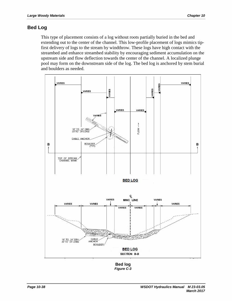
Bed Log
This type of placement consists of a log without roots partially buried in the bed and extending out to the center of the channel. This low-profile placement of logs mimics tip-first delivery of logs to the stream by windthrow. These logs have high contact with the streambed and enhance streambed stability by encouraging sediment accumulation on the upstream side and flow deflection towards the center of the channel. A localized plunge pool may form on the downstream side of the log. The bed log is anchored by stem burial and boulders as needed.