40
WASTE WATER TREATMENT Grease Separators • Hotels/restaurants • Canteens/self-service restaurants • Hospitals • Bakeries/Pastries • Butchers/delicatessen/ slaughterhouses • Fish stores, etc
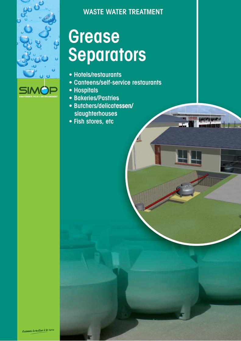
WASTE WATER TREATMENT
Grease Separators• Hotels/restaurants• Canteens/self-service restaurants• Hospitals• Bakeries/Pastries• Butchers/delicatessen/ slaughterhouses• Fish stores, etc
• Bakeries/Pastries• Butchers/delicatessen/ slaughterhouses

10 rue Richedoux 50480 SAINTE-MÈRE-ÉGLISE – FRANCE – Tél. +33 (0)2 33 95 88 00 – Fax +33 (0)2 33 21 50 75www.simop.com – e-mail : [email protected]
SIMOP
WHY CHOOSING SIMOP?
35 YEARS OF RESEARCH AND DEVELOPMENT !By choosing SIMOP, you will choose a strong business leader with 35 years
of experience and an international reputation. Our research department
impregnated with a strong spirit of innovation is constantly at the forefront
of new techniques and technologies. The strength of our research and
development allow us to continually evolve existing products launched on
the market regularly which have reliable and sustainable solutions which
contribute to improve the environment and its patented processes.
LARGE STOCKS AVAILABLE
4 INDuSTRIAL SITESFOR GREATER RESPONSIVENESS !Our French production is spread over four sites to ensure
manufacturing closest to you and delivery as soon as possible.
BORDEAUX
BOURG-DE-PÉAGE
LE HAM
MONTDIDIER
Le Ham Montdidier Bordeaux Bourg de Péage
10 rue Richedoux 50480 SAINTE-MÈRE-ÉGLISE – FRANCE – Tél. +33 (0)2 33 95 88 00 – Fax +33 (0)2 33 21 50 75www.simop.com – e-mail : [email protected] non contractuel. Les cotes (en mm) sont données à titre indicatif et peuvent être modifi ées sans préavis.
SIMOP1
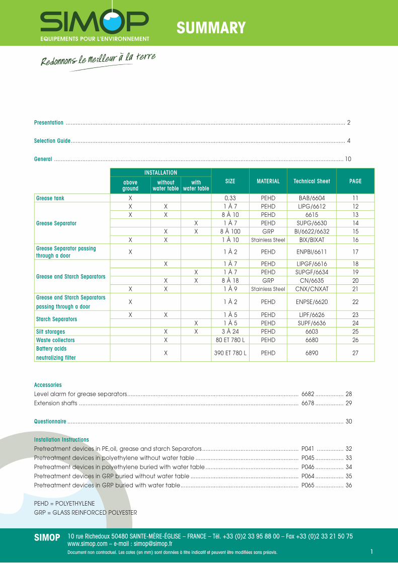
SUMMARY
Presentation ........................................................................................................................................................................ 2
Selection Guide ..................................................................................................................................................................... 4
General .............................................................................................................................................................................. 10
Accessories
Level alarm for grease separators ....................................................................................................... 6682 ................. 28
Extension shafts .................................................................................................................................... 6678 ................. 29
Questionnaire ...................................................................................................................................................................... 30
Installation Instructions
Pretreatment devices in PE,oil, grease and starch Separators .......................................................... P041 ................ 32
Pretreatment devices in polyethylene without water table .............................................................. P045 ................. 33
Pretreatment devices in polyethylene buried with water table ........................................................ P046 ................. 34
Pretreatment devices in GRP buried without water table ................................................................. P064 ................. 35
Pretreatment devices in GRP buried with water table ....................................................................... P065 ................. 36
PEHD = POLYETHYLENE
GRP = GLASS REINFORCED POLYESTER
INSTALLATIONSIZE MATERIAL Technical Sheet PAGEabove
groundwithout
water tablewith
water table
Grease tank X 0,33 PEHD BAB/6604 11
Grease Separator
X X 1 À 7 PEHD LIPG/6612 12X X 8 À 10 PEHD 6615 13
X 1 À 7 PEHD SUPG/6630 14X X 8 À 100 GRP BI/6622/6632 15
X X 1 À 10 Stainless Steel BIX/BIXAT 16Grease Separator passing through a door
X 1 À 2 PEHD ENPBI/6611 17
Grease and Starch Separators
X 1 À 7 PEHD LIPGF/6616 18X 1 À 7 PEHD SUPGF/6634 19
X X 8 À 18 GRP CN/6635 20X X 1 À 9 Stainless Steel CNX/CNXAT 21
Grease and Starch Separators
passing through a doorX 1 À 2 PEHD ENPSE/6620 22
Starch SeparatorsX X 1 À 5 PEHD LIPF/6626 23
X 1 À 5 PEHD SUPF/6636 24Silt storages X X 3 À 24 PEHD 6603 25Waste collectors X 80 ET 780 L PEHD 6680 26Battery acids
neutralizing filterX 390 ET 780 L PEHD 6890 27

10 rue Richedoux 50480 SAINTE-MÈRE-ÉGLISE – FRANCE – Tél. +33 (0)2 33 95 88 00 – Fax +33 (0)2 33 21 50 75www.simop.com – e-mail : [email protected] non contractuel. Les cotes (en mm) sont données à titre indicatif et peuvent être modifi ées sans préavis.
SIMOP2
A COMPANY AT THE CUTTING EDGE OF TECHNOLOGY
The widest range on the marketBased on our 35 years of technical and industrial experience, we offer polyethylene and polyester grease separators constituting the multi-line materials range the widest on the market.
1) Grease level sensor2) Remote drain system3) Sprinkler system for starch separator4) Interior view of a separator
An integrated test basePrior to be launched on the market, all devices are tested on our test base. This base allows the validation of the suitability of the products in their employment contexts (groundwater, backfi ll loads,...). Finally, our polyethylene and GRP devices are subject to quality control and traceability are guaranteed for 20 years against corrosion.
1
3
4
2

10 rue Richedoux 50480 SAINTE-MÈRE-ÉGLISE – FRANCE – Tél. +33 (0)2 33 95 88 00 – Fax +33 (0)2 33 21 50 75www.simop.com – e-mail : [email protected] non contractuel. Les cotes (en mm) sont données à titre indicatif et peuvent être modifi ées sans préavis.
SIMOP3
A MULTI-MATERIAL PRODUCTIONSimop offers a complete range of grease separators in polyester and polyethylene.Their production uses different technologies to meet your needs.
PolyethyleneSimop has 35 years of experience in the manufacture of rotational molding.Our industrial facilities allow us to manufacture the larger monobloc parts in Europe (35 m3).This ensures easy implementation and maintenance, perfect sealing of our devices and has the advantage of being recyclable.
WARRANTY20 YEARSAGAINST
CORROSION
Rotomolded partRotomolding
SeparatorFilament Winding
PolyesterOur method, based on the principle of fi lament winding, fully automated, provides continuity of production with a perfect control of the fi nished product and optimization of mechanical strength.
WARRANTY20 YEARSAGAINST
CORROSION
WARRANTY
10 YEARS AGAINST
CORROSION
Stainless steelWe offer stainless steel devices on demand for effl uents greater than 70 °.

10 rue Richedoux 50480 SAINTE-MÈRE-ÉGLISE – FRANCE – Tél. +33 (0)2 33 95 88 00 – Fax +33 (0)2 33 21 50 75www.simop.com – e-mail : [email protected] non contractuel. Les cotes (en mm) sont données à titre indicatif et peuvent être modifi ées sans préavis.
SIMOP4
SELECTION GUIDE
How to choose your separator depending on the premises?
Choosing your separator
*Preparing a meal gives out greasy, oily residues as well as solid matter.A potato peeler brings out foam and debris.
If these waste water are directly discharged to the drains, these discharges can not only cause blocking but also interfere with the proper functioning of the treatment water plants.
Food trade and industries professionals have, according to the type of the discharges due to their activity, to be equipped with a grease separator and/or starch separator with a silt storage.
Choosing a device adapted to the constraints of installation
(see summary)
Catering, workshops preparing meat
Determining the treatment type*
Dimensioning Calculation (Table pages 5 to 7)
Choosing a deviceadapted to the installation type
(see summary)
Backeries/pastries, fi sh stores, other agri-food
industries
Entering and sending aSIMOP questionnaire (page 30)
Dimensioning Calculation

10 rue Richedoux 50480 SAINTE-MÈRE-ÉGLISE – FRANCE – Tél. +33 (0)2 33 95 88 00 – Fax +33 (0)2 33 21 50 75www.simop.com – e-mail : [email protected] non contractuel. Les cotes (en mm) sont données à titre indicatif et peuvent être modifi ées sans préavis.
SIMOP5
TRADITIONAL FOODRESTAURANTS, HOTELS, HOSPITALSDIMENSIONING TABLE
*In principle, we consider the grease density is 0.94, the effl uent temperature is up to 60°C and the presence factor of detergents is 1.3 (occasionally or always).
If the density, temperature and detergents factor are different, send us back the questionnaire (page 30) completed.
Grease separators / grease starch separators
Starch separator
Hotel Restaurant 1 service Restaurant 2 services Hospital
Daily duration of activity 16h00 8h00 16h00 12h00
Size * Number of meals per day
1 1 to 89 1 to 53 1 to 105 1 to 111
2 90 to 178 54 to 105 106 to 209 112 to 222
3 179 to 266 106 to 157 210 to 313 223 to 444
4 267 to 355 158 to 209 314 to 418 334 to 444
5 356 to 444 210 to 261 419 to 522 445 to 554
6 445 to 532 262 to 313 523 to 626 555 to 665
7 533 to 621 314 to 365 627 to 730 666 to 776
8 622 to 709 366 to 418 731 to 835 777 to 887
9 710 to 798 419 to 470 836 to 939 888 to 997
10 799 to 887 471 to 522 940 to 1043 998 to 1108
11 888 to 975 523 to 574 1044 to 1147 1109 to 1219
12 976 to 1064 575 to 626 1148 to 1252 1220 to 1330
13 1065 to 1152 627 to 678 1253 to 1356 1331 to 1440
14 1153 to 1241 679 to 730 1357 to 1460 1441 to 1551
15 1242 to 1330 731 to 782 1461 to 1564 1552 to 1662
16 1331 to 1418 783 to 835 1565 to 1669 1663 to 1773
17 1419 to 1507 836 to 887 1670 to 1773 1774 to 1884
18 1508 to 1596 888 to 939 1774 to 1877 1885 to 1994
19 1597 to 1684 940 to 991 1878 to 1981 1995 to 2105
20 1685 to 1773 992 to 1043 1982 to 2086 2106 to 2216
Size Number of meals per day Mass of potatoes per day (kg)
1 350 75
2 930 200
3 2300 500
4 4600 1000
5 6900 1500

10 rue Richedoux 50480 SAINTE-MÈRE-ÉGLISE – FRANCE – Tél. +33 (0)2 33 95 88 00 – Fax +33 (0)2 33 21 50 75www.simop.com – e-mail : [email protected] non contractuel. Les cotes (en mm) sont données à titre indicatif et peuvent être modifi ées sans préavis.
SIMOP6
*In principle, we consider the grease density is 0.94, the effl uent temperature is up to 60°C and the presence factor of detergents is 1.3 (occasionally or always).
If the density, temperature and detergents factor are different, send us back the questionnaire (page 30) completed.
DINING AREAS,CANTEENS,SELF-SERVICE RESTAURANTS,OFFICES, FACTORIES...DIMENSIONING TABLE
Grease separator/ Grease and starch separator
Starch Separator
Self-service Heated kitchen
Daily duration of activity 18h00 8h00
Size * Number of meals per day
1 1 to 227 1 to 222
2 228 to 454 223 to 444
3 455 to 680 445 to 665
4 681 to 907 666 to 887
5 908 to 1133 888 to 1108
6 1134 to 1360 1109 to 1330
7 1361 to 1587 1331 to 1551
8 1588 to 1813 1552 to 1773
9 1814 to 2040 1774 to 1994
10 2041 to 2266 1995 to 2216
11 2267 to 2493 2217 to 2437
12 2494 to 2719 2438 to 2659
13 2720 to 2946 2660 to 2880
14 2947 to 3173 2881 to 3102
15 3174 to 3399 3103 to 3324
16 3400 to 3626 3325 to 3545
17 3627 to 3852 3546 to 3767
18 3853 to 4079 3768 to 3988
19 4080 to 4305 3989 to 4210
20 4306 to 4532 4211 to 4431
Size Number of meals per day Mass of potatoes per day (kg)
1 350 75
2 930 200
3 2300 500
4 4600 1000
5 6900 1500

10 rue Richedoux 50480 SAINTE-MÈRE-ÉGLISE – FRANCE – Tél. +33 (0)2 33 95 88 00 – Fax +33 (0)2 33 21 50 75www.simop.com – e-mail : [email protected] non contractuel. Les cotes (en mm) sont données à titre indicatif et peuvent être modifi ées sans préavis.
SIMOP7
BUTCHERS / DELICATESSENSLAUGHTERHOUSESDIMENSIONING TABLE
Daily duration of activity8 hours 16 hours 24 hours
Pig / week Cattle / week size* size* size*
LITTLE ENTER-PRISE**
2,5 1 1 – –5 2 2 – –
7,5 3 2 1 –10 4 3 2 –
12,5 5 3 2 –
MEDIUM ENTER-PRISE**
15 6 3 2 117,5 7 4 2 220 8 4 2 2
22,5 9 5 3 225 10 5 3 2
LARGE ENTER-PRISE**
27,5 11 4 2 230 12 5 3 2
32,5 13 5 3 235 14 6 3 2
37,5 15 6 3 240 16 6 3 2
42,5 17 7 4 345 18 7 4 3
47,5 19 7 4 350 20 8 4 3
52,5 21 8 4 355 22 8 4 3
57,5 23 9 5 360 24 9 5 3
62,5 25 10 5 465 26 10 5 4
67,5 27 10 5 470 28 11 6 4
72,5 29 11 6 475 30 11 6 4
77,5 31 12 6 480 32 12 6 4
82,5 33 12 6 485 34 13 7 5
87,5 35 13 7 590 36 13 7 5
92,5 37 14 7 595 38 14 7 5
97,5 39 15 8 5100 40 15 8 5
*In principle, we consider the grease density is 0.94, the effl uent temperature is up to 60°C and the presence factor of detergents is 1.3 (occasionally or always).
If the data is different, please contact us.** As defi ned in the standard EN1825-2

10 rue Richedoux 50480 SAINTE-MÈRE-ÉGLISE – FRANCE – Tél. +33 (0)2 33 95 88 00 – Fax +33 (0)2 33 21 50 75www.simop.com – e-mail : [email protected] non contractuel. Les cotes (en mm) sont données à titre indicatif et peuvent être modifi ées sans préavis.
SIMOP8
BAKERIES / PASTRIES,FISH STORES AND OTHER FOOD INDUSTRIES, SPECIAL CASESDIMENSIONING
Bakeries/PastriesThe size is calculated based on the amount of oil products used daily (oil, butter, margarine), effl uent temperature, the presence or absence of milk.
It is necessary to send us the Special Technical Specifi cations (STS) coming from a technical engineering department to determine the sizing of your separator. To do this, you can photocopy, complete and return the questionnaire on page 30.
Fish storesThere is little fat. To retain scales and fi sh bones, a waste collector (page 26) may be installed upstream to prohibit the disposal of litter in the network. The size is calculated based on the tonnage handled per day and the fl ow rate of rinse water in the room.
It is necessary to send us the Special Technical Specifi cations (STS) coming from a technical engineering department to determine the sizing of your separator. To do this, you can photocopy, complete and return the questionnaire on page 30.
Special ApplicationsWhen terracing or installation in a cellar is not possible, in the case of a restaurant from 15 to 20 seats per day (on 8 hours), in the case of a fast food (kebab, pizzeria) or in the case of a place with only washing up (disposable dishes or take out, so quite small grease releases), the grease tank under the kitchen sink can be a derogatory solution, see page 11.
10 rue Richedoux 50480 SAINTE-MÈRE-ÉGLISE – FRANCE – Tél. +33 (0)2 33 95 88 00 – Fax +33 (0)2 33 21 50 75www.simop.com – e-mail : [email protected] non contractuel. Les cotes (en mm) sont données à titre indicatif et peuvent être modifi ées sans préavis.
SIMOP9
OPTIONAL ACCESSORIES
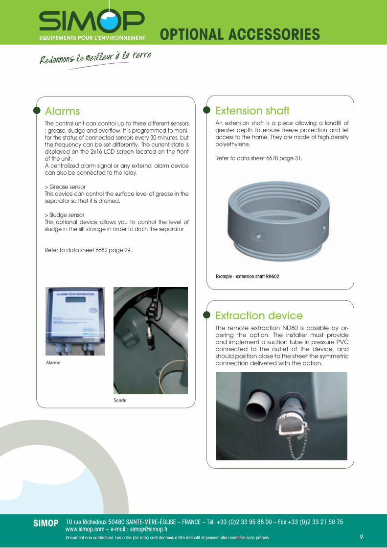
AlarmsThe control unit can control up to three different sensors : grease, sludge and overfl ow. It is programmed to moni-tor the status of connected sensors every 30 minutes, but the frequency can be set differently. The current state is displayed on the 2x16 LCD screen located on the front of the unit.A centralized alarm signal or any external alarm device can also be connected to the relay.
> Grease sensorThis device can control the surface level of grease in the separator so that it is drained.
> Sludge sensorThis optional device allows you to control the level of sludge in the silt storage in order to drain the separator
Refer to data sheet 6682 page 29.
Extension shaftAn extension shaft is a piece allowing a landfi ll of greater depth to ensure freeze protection and let access to the frame. They are made of high density polyethylene.
Refer to data sheet 6678 page 31.
Extraction deviceThe remote extraction ND80 is possible by or-dering the option. The installer must provide and implement a suction tube in pressure PVC connected to the outlet of the device, and should position close to the street the symmetric connection delivered with the option.
Example : extension shaft RH602
Sonde
Alarme

10 rue Richedoux 50480 SAINTE-MÈRE-ÉGLISE – FRANCE – Tél. +33 (0)2 33 95 88 00 – Fax +33 (0)2 33 21 50 75www.simop.com – e-mail : [email protected] non contractuel. Les cotes (en mm) sont données à titre indicatif et peuvent être modifi ées sans préavis.
SIMOP10
GENERAL
UseLaw N°75-633 dated July 15 1975, the Environmental Code, the Water Act dated January 3 1992, the code of public health and the inter-communal or sanitation regulations prohibit the discharge into wastewater which may be harmful to the environment or health. Professionals of the catering industry and food industries are forced, depending on the type of discharges due to their activity, to be equipped with a grease and/or starch tank, preceded by a silt storage.
MaintenanceNF EN 1825-2 indicates that the device should be checked, drained and cleaned regularly (at least once a month, preferably every 15 days) by a specialized company. Grease and sludge level alarms, available as options, allow the user to be notifi ed as soon as the retention capacity of either of these elements is reached.After each discharge, it is imperative to completely fi ll the separator with cold water.
Defi nitionA grease separator is a device used for separating and storing solids, greases and oils of animal and vegetable origin, contained in the waste water.A V100 silt storage is incorporated into every device except the grease tank under the kitchen sink.Our devices - except the grease tank under the kitchen sink - are in accordance with standard NF EN 1825-1 and are CE marked.Grease retention capacity is 40 liters per l/s.
Remote extraction deviceThe remote extraction ND80 is possible by ordering the option. The installer must provide and implement a suction tube in pressure PVC connected to the outlet of the device, and should position close to the street the symmetric connection delivered with the option.
Effl uent temperatureThe maximum temperatureof the effl uent in inlet is 70 °.
Implementation1) Limits :Grease separators should be used only for wastewater containing greases and oils of organic origin. Do not introduce into the wastewater separator containing fecal waste, rain water and waste water containing light liquids (grease or oil of mineral origin)2) Place of implementation :It is necessary to install the grease separators close to waste water sources, but as far as possible, in unventilated areas, in areas of passage or parking of vehicles or in storage areas . They should be easily accessible to cleaning vehicles. It is necessary to establish the grease tanks to avoid damage due to frost action, and so that all items requiring regular maintenance are accessible at any time.3) Discharge of and to the separator :Pipes upstream from the separator must be installed with a minimum slope of 2% in order to avoid an accumulation of grease. The transition between the vertical and horizontal lines should be using two 45 °elbows connected by a connection of at least 250 mm long, or with an equivalent radius elbow. It should be followed by a line for a distance in millimeters at least 10 times the diameter of the feeding pipe.4) Aeration :The pipes connected to grease tanks, upstream and downstream must be suffi ciently ventilated. The inlet pipe must be provided with a vent. When the nearest vent is located more than 10 m upstream of the separator, additional ventilation should be installed as close as possible to the device.
General information on grease separators and grease and starch separators
10 rue Richedoux 50480 SAINTE-MÈRE-ÉGLISE – FRANCE – Tél. +33 (0)2 33 95 88 00 – Fax +33 (0)2 33 21 50 75www.simop.com – e-mail : [email protected] non contractuel. Les cotes (en mm) sont données à titre indicatif et peuvent être modifi ées sans préavis.
SIMOP11
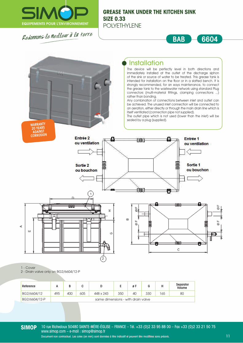
GREASE TANK UNDER THE KITCHEN SINKSIZE 0.33POLYETHYLENE
6604BAB
Reference A B C D E ø F G H Separator Volume
BG2/6604/12 495 400 605 448 x 243 350 40 330 165 80
BG2/6604/12-P same dimensions - with drain valve
1 - Cover2 - Drain valve only on BG2/6604/12-P
InstallationThe device will be perfectly level in both directions and immediately installed at the outlet of the discharge siphon of the sink or source of water to be treated. This grease tank is intended for installation on the fl oor or in a slatted bench. It is strongly recommended, for an eays maintenance, to connect the grease tank to the wastewater network using standard Plug connectors (multi-material fi ttings, clamping connections ...) rather than bonding.Any combination of connections between inlet and outlet can be achieved. The unused inlet connection will be connected to an aeration, either directly or through the main drain line which is itself ventilated (connection pipe not supplied).The outlet pipe which is not used (lower than the inlet) will be sealed by a plug (supplied).
WARRANTY20 YEARSAGAINST
CORROSION

10 rue Richedoux 50480 SAINTE-MÈRE-ÉGLISE – FRANCE – Tél. +33 (0)2 33 95 88 00 – Fax +33 (0)2 33 21 50 75www.simop.com – e-mail : [email protected] non contractuel. Les cotes (en mm) sont données à titre indicatif et peuvent être modifi ées sans préavis.
SIMOP12
GREASE SEPARATOR APOLLO LINEV100 SILT STORAGE - SIZE 1 TO 7 uNDERGROuND INSTALLATION (WITHOuT WATER TABLE) OR ABOVE GROuND - IN POLYETHYLENE
Installation
(see installation instructions P045)The device must be buried on a non-hydromorphous ground or with no water table. Otherwise, it should be installed above ground.Underground installation : if vehicles or rolling loads drive over the area and if the height is greater than 400 mm above the device, a slab protection of reinforced concrete resting on undisturbed ground will be poured in order to the separator does not suffer the loads directly.Above ground installation : the device will be positioned on a level on a fl at surface and smooth on the entire surface of the device. The cover always remain accessible for maintenance. Aeration as high as possible above the ridge will be provided to evacuate gases. We recommend a minimum diameter of 100 mm including a device preventing the passage of insects and small animals.
6612LIPG
1 - Screw-on extension shaft (RH602), height 250 mm. Option2 - Extraction device ND80 (see table below). OptionGrease level alarm, see page 28. Option
Reference Size A ø B ø D E ø F G H Silt storage Volume
SeparatorVolume Extraction Device
SG2/6612/01 1 765 1244 600 485 100 415 350 103 262 OD4-BBTN1
SG2/6612/02 2 1059 1244 600 779 100 709 350 205 509 OD4-BBTN2SG2/6612/03 3 1366 1244 600 1076 100 1006 350 306 756 OD4-BBTN3SG2/6612/04 4 1100 1720 600 825 100 755 345 416 982 OD4-BBTN4SG2/6612/05 5 1330 1720 600 975 160 905 425 526 1228 OD4-BBTN5SG2/6612/06 6 1475 1720 600 1120 160 1050 425 612 1468 OD4-BBTN6SG2/6612/07 7 1635 1720 600 1280 160 1210 425 722 1720 OD4-BBTN7
EN858-1EN 1825-1
20 YEAR WARRANTY
AGAINSTCORROSION

10 rue Richedoux 50480 SAINTE-MÈRE-ÉGLISE – FRANCE – Tél. +33 (0)2 33 95 88 00 – Fax +33 (0)2 33 21 50 75www.simop.com – e-mail : [email protected] non contractuel. Les cotes (en mm) sont données à titre indicatif et peuvent être modifi ées sans préavis.
SIMOP13
GREASE SEPARATORV100 SILT STORAGE - SIZE 8 TO 10uNDERGROuND INSTALLATION (NO WATER TABLE)IN POLYETHYLENE
Installation (see installation instructions P041)
The device must be buried as close as possible to the place to be treated. Its cover must reach the ground level. The bottom of the hole must be perfectly fl at and covered with 10 cm of sand. Backfi ll with sand and in any case with stone or gravel.
If vehicles or rolling loads drive over the area or if extension shafts are used, it is necessary to pour a concrete slab resting on the undisturbed ground in order to the separator does not suffer the loads directly.
Aeration must be connected (recommended diameter of 100 mm), a device preventing the passage of insects and small animals is included.
In case of groundwater, ground liable to fl ooding, hydromorphous soil or non stabilized ground, use our steel separators range.
6615
2 - Extraction device (see table below).OptionGrease alarm separator, see page 28. Option
Reference Size A B C ø D E ø F G H Silt storage Volume
SeparatorVolume
Number of manholes
Extraction Device
SG2/6615/08/00 8 2050 1540 2340 750 1220 160 1150 900 800 2350 2 OD2/105
SG2/6615/10/00 10 2050 1540 2340 750 1320 160 1250 800 1000 2490 2 OD2/105
EN858-1EN 1825-1
20 YEAR WARRANTY
AGAINSTCORROSION

10 rue Richedoux 50480 SAINTE-MÈRE-ÉGLISE – FRANCE – Tél. +33 (0)2 33 95 88 00 – Fax +33 (0)2 33 21 50 75www.simop.com – e-mail : [email protected] non contractuel. Les cotes (en mm) sont données à titre indicatif et peuvent être modifi ées sans préavis.
SIMOP14
GREASE SEPARATOR APOLLO LINEV100 SILT STORAGE - SIZE 1 TO 7 INSTALLATION ON GROuND WITH WATER TABLE AND/OR WITHOuT CONCRETE SLAB - uP TO A 800 MM BACKFILL HEIGHTIN POLYETHYLENE
Installation
(see installation instructions P046)Small communities, industrial facilities, collective kitchens, restaurants,... have to be equipped with a grease separator according to the code of public health and the inter-communal or sanitation regulations.Food industries have to send us the STS (Special Technical Specifi cations) in order to calculate the appropriate size of the device.
6630SuPG
1 -Screw-on estension shafts height 250 mm (Ref. RH602). Option2 -Extraction device (Ref. ND 80). OptionGrease level alarm, see page 28. Option
Reference Size A ø B ø D E ø F G H Silt storage Volume
SeparatorVolume
Extraction Device
SG2/6630/01 1 765 1244 600 485 100 415 350 103 262 OD4-BBTN1
SG2/6630/02 2 1059 1244 600 779 100 709 350 205 509 OD4-BBTN2
SG2/6630/03 3 1356 1244 600 1076 100 1006 350 306 756 OD4-BBTN3
SG2/6630/04 4 1100 1720 600 825 100 755 345 416 982 OD4-BBTN4
SG2/6630/05 5 1330 1720 600 975 160 905 425 526 1228 OD4-BBTN5
SG2/6630/06 6 1475 1720 600 1120 160 1050 425 612 1468 OD4-BBTN6
SG2/6630/07 7 1635 1720 600 1280 160 1210 425 722 1720 OD4-BBTN7
EN858-1EN 1825-1
20 YEAR WARRANTY
AGAINSTCORROSION

10 rue Richedoux 50480 SAINTE-MÈRE-ÉGLISE – FRANCE – Tél. +33 (0)2 33 95 88 00 – Fax +33 (0)2 33 21 50 75www.simop.com – e-mail : [email protected] non contractuel. Les cotes (en mm) sont données à titre indicatif et peuvent être modifi ées sans préavis.
SIMOP15
GREASE SEPARATORV100 SILT STORAGE - SIZE 8 TO 100 UNDERGROUND INSTALLATION (WITH OR WITHOUT WATER TABLE)IN GRP
6622/6632BI
1 - Snare + screw-dawn cover (ref. OD3/CV600 / ...), Ø 600. Option2 - Screw-dawn extension shafts (ref. RH602), Ø 600, height 250 mm.Option3 -Remote extraction device ND80 (ref. OD3/1924). Option4 - Aeration F Ø 100.
Snare + screw-dawn cover (OD3/CV600/13), Ø 600 on ferrule Ø 1300. Option
Snare + screw-dawn cover (OD3/CV600/16), Ø 600 on ferrule Ø 1600. Option
Screw-dawn extension shafts (RH602), Ø 600, height 250 mm. The optional screw-dawn cover must also be ordered. Option
Grease level alarm, see page 28. Option
Remote extraction device ND80. Option
Anchoring strap (CA3/6394/10T) for an installation on ground with a water table or on hydromorphous ground, for a Ø 1300 or Ø 1600 tank.Option
EN858-1EN 1825-1
20 YEAR WARRANTY
AGAINSTCORROSION
Installation
(see installation instructions P064/P065)Implementation of the grease separators is defi ned by the standard NF EN 1825-2. The device must be buried outside the building and as close as possible to the area to be treated. Manhole(s) always remain accessible for maintenance. We recommended a diameter of 100 mm for aeration, a device preventing the passage of insects and small animals is included. Ventilation spurs are made standard but must be blocked if effi cient ventilation of the network is already present.
Reference TN A ø B C ø D E ø F G H Silt storage Volume
SeparatorVolume
Number anchoring straps
Number of manholes
SG3/6622/08 8 1470 1320 2738 750 1070 160 1000 470 811 1960 2 1
SG3/6622/10 10 1470 1320 3338 750 1070 160 1000 470 1010 2412 2 1
SG3/6622/12 12 1792 1642 2706 750 1330 200 1260 532 1228 2961 2 1
SG3/6622/15 15 1792 1642 3276 750 1330 200 1260 532 1523 3619 2 1
SG3/6622/18 18 1792 1642 3896 750 1330 200 1260 532 1843 4334 2 1
SG3/6632/16020 20 1832 1642 4352 750 1320 200 1250 582 2013 4850 2 2
SG3/6632/16025 25 1832 1642 5612 750 1270 250 1200 632 2530 6049 2 2
SG3/6632/19030 30 2133 1940 4582 750 1570 250 1500 633 3022 7238 2 2
SG3/6632/19035 35 2133 1940 5702 750 1460 315 1390 743 3513 8415 2 2
SG3/6632/19040 40 2133 1940 6452 750 1460 315 1390 743 4007 9606 2 2
SG3/6632/23045 45 2557 2374 5112 750 1900 315 1830 727 4721 12014 3 2
SG3/6632/23050 50 2557 2374 5662 750 1900 315 1830 727 5315 13330 3 2
SG3/6632/23060 60 2557 2374 6712 750 1900 315 1830 727 6450 15843 3 2
SG3/6632/23070 70 2557 2374 7812 750 1900 315 1830 727 7638 18475 4 2
SG3/6632/23080 80 2557 2374 8912 750 1900 315 1830 727 8826 21108 4 2
SG3/6632/23090 90 2557 2374 9972 750 1900 315 1830 727 9970 23645 5 2
SG3/6632/23100 100 2557 2374 11062 750 1900 315 1830 727 11147 26253 5 2

10 rue Richedoux 50480 SAINTE-MÈRE-ÉGLISE – FRANCE – Tél. +33 (0)2 33 95 88 00 – Fax +33 (0)2 33 21 50 75www.simop.com – e-mail : [email protected] non contractuel. Les cotes (en mm) sont données à titre indicatif et peuvent être modifi ées sans préavis.
SIMOP16
Important : Regular maintenance of this equipment according to standard EN 1825-2 is required.Read the installation instructions concerning steel grease separators.
Manholes : the closing system (extension shaft(s) and cover(s)) according to EN 124, is not supplied.
Total accessibility : this grease separator may be completed by an extension shaft according to the water level (heights are available on request). Beyond a load of 125 kN, the separator is equipped with an extension shaft. See option extension shaft RHX page 29.
Man
hole
Re
fere
nce
Tota
l Ace
ssib
ility
Re
fere
nce
Nom
inal
Siz
e
Silt
stor
age
Vol.
(l)
Sepa
rato
r Vol
. (l)
Gre
ase
Vol.
(l)
Leng
th (
L) m
m
Wid
th m
m
Hei
ght H
(m
m)
Inle
t lev
el (
T1)
mm
Out
let l
evel
(T2
)
mm
ND
con
nect
ion
Nb
Man
hole
(s)
Wei
ght (
kg)
empt
y
Nb
Cove
r (s)
Wei
ght (
kg)
empt
y
BIX BIXAT BIX BIXAT
BI01XAMCH BI01X025B 1 100 240 71 765 670 915 180 250 110 1 98 1 (575x670) 142
BI02XAMCH BI02X025B 2 200 711 175 1335 765 1150 180 250 110 1 152 2 (575x670) 241
BI04XAMCH BI04X025B 4 400 973 246 2000 765 1150 180 250 110 2 195 3 (575x670) 330
BI05XAMCH BI05X030B 5 500 1324 335 2000 1015 1200 230 300 110 2 280 3 (575x920) 442
BI06XAMCH BI06X030B 6 600 1827 472 2665 1015 1200 230 300 160 2 342 4 (575x920) 558
BI08XAMCH BI08X030B 8 800 2239 584 3330 1015 1200 230 300 160 2 404 5 (575x920) 673
BI10XAMCH BI10X030B 10 1000 2562 696 3995 1015 1200 230 300 160 2 463 6 (575x920) 786
GREASE SEPARATORV100 SILT STORAGE - SIZE 1 TO 10 UNDERGROUND INSTALLATION (WITHOUT WATER TABLE) OR ABOVE GROUND STAINLESS STEEL
BIXATBIX
Technical Defi nitionThese grease separators with silt storage are designed according to standard EN 1825-1 and are CE marked (Decree of 27 January 2006) and operate by gravity fl ow.The county’s health regulations and the code of public health require the installation of grease tanks.
• Made of stainless steel 304 L (EN 1.4307)• Connection by fi tting Female-Female• Equipped as standard with support for grease level
detector.• Above ground installation or buried, with the possibility of
manufacturing on site (contact us)
Option : remote suction, withdrawing device ND 80.
• Manhole(s) (diameter 600, height 120mm) without cover (s)• Total accessibility with odour proof cover thanks to
hydraulic frame(s) 15, 125, 250, 400 kn, and cam, closing type to choose, refer to data sheet RHX.
EN858-1EN 1825-1
EN858-1EN 1825-1
BIX
BIXAT
20 YEAR WARRANTY
AGAINSTCORROSION

10 rue Richedoux 50480 SAINTE-MÈRE-ÉGLISE – FRANCE – Tél. +33 (0)2 33 95 88 00 – Fax +33 (0)2 33 21 50 75www.simop.com – e-mail : [email protected] non contractuel. Les cotes (en mm) sont données à titre indicatif et peuvent être modifi ées sans préavis.
SIMOP17
GREASE SEPARATORSILT STORAGE V100 - SIZE 1-2ABOVE GROUND INSTALLATION AND DOOR PASSAGEIN POLYETHYLENE
6611
Reference Size A B C D D1 E F G H Silt storageVolume
Separator Volume Extraction Device
SG2/6611/01 1 1060 700 1246 625 287 815 110 745 315 100 380 OD2/109
SG2/6611/02 2 1060 700 1827 625 635 815 110 745 315 200 515 OD2/109
Extraction device ND 80 (OD2/109), on right wall fl ow direction. OptionGrease level alarm, see page 28. Option
InstallationThe device is installed on the level and as close as possible to the place to be treated. It will be installed above ground on a perfectly fl at and smooth surface on the entire surface of the device. Manhole(s) always remain accessible for maintenance. We recommend a minimum diameter of 50 for aeration pipe which will be equipped with a device preventing the passage of insects and small animals.
EN858-1EN 1825-1
20 YEAR WARRANTY
AGAINSTCORROSION
ENPBI

10 rue Richedoux 50480 SAINTE-MÈRE-ÉGLISE – FRANCE – Tél. +33 (0)2 33 95 88 00 – Fax +33 (0)2 33 21 50 75www.simop.com – e-mail : [email protected] non contractuel. Les cotes (en mm) sont données à titre indicatif et peuvent être modifi ées sans préavis.
SIMOP18
GREASE AND STARCH SEPARATORAPOLLO RANGE - SILT STORAGE V100 - SIZE 1 TO 7UNDERGROUND INSTALLATION (NO WATER TABLE)IN POLYETHYLENE
Installation
(see installation instructions P045)The device must be buried on a non-hydromorphous ground or with no water table. Otherwise, it should be installed above ground.
underground installation : if vehicles or rolling loads drive over the area and if the height is greater than 400 mm above the device, a slab protection of reinforced concrete resting on undisturbed ground will be poured in order to the separator does not suffer the loads directly.
Above ground installation : the device will be positioned on a level on a fl at surface and smooth on the entire surface of the device. The cover always remain accessible for maintenance. Aeration as high as possible above the ridge will be provided to evacuate gases. We recommend a minimum diameter of 100 mm including a device preventing the passage of insects and small animals.
6616LIPGF
1 - Screw-on extension shaft (RH602), height 250.Option2 - Extraction device ND 80, see table below. Option3 - Threaded fi tting for ND 20 spray nozzle.
Centres grease inlet / starch inlet :_size 1, 2 and 3 .....160- size 4 ...................180- size 5, 6 et 7 ........190
Grease level alarm, see page 28. Option
Reference Size A ø B ø D E ø F G H Silt storage Volume
Separator Volume
Extraction device
SG2/6616/01 1 765 1244 600 485 100 415 350 103 262 OD4-BBTN1
SG2/6616/02 2 1059 1244 600 779 100 709 350 509 509 OD4-BBTN2
SG2/6616/03 3 1356 1244 600 1076 100 1006 350 306 756 OD4-BBTN3
SG2/6616/04 4 1100 1720 600 825 100 755 345 416 982 OD4-BBTN4
SG2/6616/05 5 1330 1720 600 975 160 905 425 526 1228 OD4-BBTN5
SG2/6616/06 6 1475 1720 600 1120 160 1050 425 612 1468 OD4-BBTN6
SG2/6616/07 7 1635 1720 600 1280 160 1210 425 722 1720 OD4-BBTN7
EN858-1EN 1825-1
20 YEAR WARRANTY
AGAINSTCORROSION

10 rue Richedoux 50480 SAINTE-MÈRE-ÉGLISE – FRANCE – Tél. +33 (0)2 33 95 88 00 – Fax +33 (0)2 33 21 50 75www.simop.com – e-mail : [email protected] non contractuel. Les cotes (en mm) sont données à titre indicatif et peuvent être modifi ées sans préavis.
SIMOP19
GREASE AND STARCH SEPARATORAPOLLO RANGE SILT STORAGE V100 - SIZE 1 TO 7UNDERGROUND INSTALLATION ON GROUND WITH A WATER TABLE OR INS-TALLATION WITHOUT CONCRETE SLAB - EMBANKMENT HEIGHT TO 800 MMIN POLYETHYLENE
6634SuPGF
Installation
(see installation instructions P046)The device will be buried. it is intended to be installed in the presence of water table or on hydromorphous ground at a level not exceeding the device upper cone.
if vehicles or rolling loads drive over the area and if the height is greater than 800 mm above the device, a slab protection of reinforced concrete resting on undisturbed ground will be poured in order to the separator does not suffer the loads directly.The cover always remain accessible for maintenance.
An aeration should be provided to evacuate gases as high as possible above the ridge.
We recommend a minimum diameter of 100 mm including a device preventing the passage of insects and small animals.
1 - Screw-on extension shaft (RH602), height 250. Option2 - Extraction Device ND 80, see table below. Option3 -Threaded fi tting ND 20 for spray nozzle.
Centres grease inlet / starch inlet :- size 1, 2 and 3 ....160- size 4 ...................180- size 5, 6 et 7 ........190
Grease level alarm, see page 28. Option
Reference Size A ø B ø D E ø F ø F1 G H Silt storageVolume
Separator Volume
Extraction Device
SG2/6634/01 1 765 1244 600 485 100 100 415 350 100 260 OD4-BBTN1
SG2/6634/02 2 1059 1244 600 779 100 100 709 350 200 505 OD4-BBTN2
SG2/6634/03 3 1356 1244 600 1076 100 100 1006 350 300 755 OD4-BBTN3
SG2/6634/04 4 1100 1720 600 825 100 100 755 345 400 980 OD4-BBTN4
SG2/6634/05 5 1330 1720 600 975 160 160 905 425 500 1225 OD4-BBTN5
SG2/6634/06 6 1475 1720 600 1120 160 160 1050 425 600 1468 OD4-BBTN6
SG2/6634/07 7 1635 1720 600 1280 160 160 1210 425 700 1720 OD4-BBTN7
20 YEAR WARRANTY
AGAINSTCORROSION
10 rue Richedoux 50480 SAINTE-MÈRE-ÉGLISE – FRANCE – Tél. +33 (0)2 33 95 88 00 – Fax +33 (0)2 33 21 50 75www.simop.com – e-mail : [email protected] non contractuel. Les cotes (en mm) sont données à titre indicatif et peuvent être modifi ées sans préavis.
SIMOP20
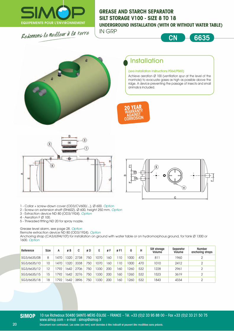
GREASE AND STARCH SEPARATORSILT STORAGE V100 - SIZE 8 TO 18UNDERGROUND INSTALLATION (WITH OR WITHOUT WATER TABLE)IN GRP
6635CN
Installation
(see installation instructions P064/P065)
Achieve aeration Ø 100 (ventilation spur at the level of the manhole) to evacuate gases as high as possible above the ridge. A device preventing the passage of insects and small animals is included.
1 - Collar + screw-dawn cover (OD3/CV600/...), Ø 600. Option2 - Screw-on extension shaft (RH602), Ø 600, height 250 mm. Option3 - Extraction device ND 80 (OD3/1924). Option4 - Aeration F Ø 100.5 - Threaded fi tting ND 20 for spray nozzle.
Grease level alarm, see page 28. OptionRemote extraction device ND 80 (OD3/1924). OptionAnchoring strap (CA3/6394/10T) for installation on ground with water table or on hydromorphous ground, for tank Ø 1300 or 1600. Option
Reference Size A ø B C ø D E ø F ø F1 G H Silt storageVolume
SeparatorVolume
Number anchoring straps
SG3/6635/08 8 1470 1320 2738 750 1070 160 110 1000 470 811 1960 2
SG3/6635/10 10 1470 1320 3338 750 1070 160 110 1000 470 1010 2412 2
SG3/6635/12 12 1792 1642 2706 750 1330 200 160 1260 532 1228 2961 2
SG3/6635/15 15 1792 1642 3276 750 1330 200 160 1260 532 1523 3619 2
SG3/6635/18 18 1792 1642 3896 750 1330 200 160 1260 532 1843 4334 2
20 YEAR WARRANTY
AGAINSTCORROSION

10 rue Richedoux 50480 SAINTE-MÈRE-ÉGLISE – FRANCE – Tél. +33 (0)2 33 95 88 00 – Fax +33 (0)2 33 21 50 75www.simop.com – e-mail : [email protected] non contractuel. Les cotes (en mm) sont données à titre indicatif et peuvent être modifi ées sans préavis.
SIMOP21
20 YEAR WARRANTY
AGAINSTCORROSION
Important : Regular maintenance of this equipment according to EN 1825-2 is required.See installation instructions for steel grease separators.
Manholes : the system of extension shaft(s) and cover(s) according to EN 124 are not supplied Franceaux.
Full accessibility : This grease separator may be equipped with an extension shaft according to the water level (heights available on request). Beyond a load of 125kN, the separator is equipped with an extension shaft. See option extension shafts page 29.
Man
hole
refe
rnce
Full
acce
ssib
ility
Refe
renc
e
Nom
inal
Siz
e
Silt
stor
age
Vol.
(l)
Sep
arat
or V
ol. (
l)
Gre
ase
Vol.
(l)
Leng
th (
L) m
m
Wid
th m
m
Hei
ght H
(m
m)
Inle
t lev
el (
T1)
mm
Out
let l
evel
(T2
) m
m
ND
con
nect
ion
Nbr
man
hole
(s)
Wei
ght (
kg)
empt
y
Nbr
cov
er(s
)
Wei
ght (
kg)
empt
y
CNX CNXAT CNX CNXAT
CN01XAMCH CN01X033B 1 160 240 61 1015 670 960 260 330 110 1 123 1 (575x670) 176
CN02XAMCH CN02X033B 2 310 480 109 1335 765 1150 260 330 110 1 157 2 (575x670) 246
CN03XAMCH CN03X033B 3 466 720 162 2000 765 1150 260 330 110 2 199 3 (575x670) 334
CN04XAMCH CN04X033B 4 600 960 297 2000 1015 1200 260 330 110 2 286 3 (575x920) 437
CN06XAMCH CN06X033B 6 889 1440 380 2665 1015 1200 260 330 160 2 354 4 (575x920) 569
CN08XAMCH CN08X033B 8 1021 1920 509 3330 1015 1200 260 330 160 2 413 5 (575x920) 682
CN09XAMCH CN09X033B 9 1350 2160 579 3995 1015 1200 260 330 160 2 475 6 (575x920) 798
GREASE AND STARCH SEPARATORWITH SILT STORAGEMANHOLES OR FULL ACCESSIBILITYIN STAINLESS STEEL
CNXATCNX
Technical Defi nitionInstallation of a grease separator with a silt storage designed according to EN 1825-1 and CE marked (Decree of January 27 2006), operating by gravity fl ow.
The inter-communal or sanitation regulations and the code of public health require the installation of grease separators.
• Made of stainless steel 304L (EN 1.4307)• Connection by fi tting FF• Equipped as standard with support for grease level detector.• Implementation elevation or buried, with the possibility of on-site production (contact us)• 2 inlets, one for grease, the other for starches, ND 100• Spray nozzle for starch inlet with a threaded connection ND 20• 3 functions in one unit : Silt storage, starch separator, grease separator
Option : remote suction, racking device ND 80
Manhole(s) (diameter 600, height 120mm) without cover(s).
Full accessibility with odour-tight covers by hydraulic frame(s) 15, 125, 250, 400kN and cam, type of coverage to choose in the data sheet RHX.
EN858-1EN 1825-1
EN858-1EN 1825-1
CNX
CNXAT

10 rue Richedoux 50480 SAINTE-MÈRE-ÉGLISE – FRANCE – Tél. +33 (0)2 33 95 88 00 – Fax +33 (0)2 33 21 50 75www.simop.com – e-mail : [email protected] non contractuel. Les cotes (en mm) sont données à titre indicatif et peuvent être modifi ées sans préavis.
SIMOP22
GREASE AND STARCH SEPARATORSILT STORAGE V100 - SIZE 1 TO 2ABOVE GROUND INSTALLATIONIN POLYETHYLENE
6620ENPSE
InstallationThe device is installed on the level and as close as possible to the place to be treated. It will be installed above ground on a perfectly fl at and smooth surface on the entire surface of the device. Manhole(s) always remain accessible for maintenance. An aeration should be provided to evacuate gases as high as possible above the ridge. We recommend a minimum diameter of 50 for aeration pipe which will be equipped with a device preventing the passage of insects and small animals.
Extraction device ND80, on right wall fl ow direction (see table below). OptionGrease level alarm, see page 28. Option
Reference Size A B C ø D D1 E ø F G H Silt storageVolume
SeparatorVolume
Extraction device
SG2/6620/01 1 1060 700 1246 625 287 815 110 745 315 100 380 OD2/109
SG2/6620/02 2 1060 700 1827 625 635 815 110 745 315 200 515 OD2/109
20 YEAR WARRANTY
AGAINSTCORROSION

10 rue Richedoux 50480 SAINTE-MÈRE-ÉGLISE – FRANCE – Tél. +33 (0)2 33 95 88 00 – Fax +33 (0)2 33 21 50 75www.simop.com – e-mail : [email protected] non contractuel. Les cotes (en mm) sont données à titre indicatif et peuvent être modifi ées sans préavis.
SIMOP23
STARCH SEPARATORAPOLLO RANGE SIZE 1 TO 5UNDERGROUND INSTALLATION (WITH NO WATER TABLE) OR ABOVE GROUND
IN POLYETHYLENE6626LIPF
Reference Size A ø B D E ø F G H Silt storageVolume
SeparatorVolume Extraction Device
SF2/6626/01 1 765 1244 600 485 100 415 350 103 262 OD4-BBTN1SF2/6626/02 2 1059 1244 600 779 100 709 350 205 509 OD4-BBTN2SF2/6626/03 3 1356 1244 600 1076 100 1006 350 306 756 OD4-BBTN3SF2/6626/04 4 1100 1720 600 825 100 755 345 416 982 OD4-BBTN4SF2/6626/05 5 1330 1720 600 975 160 905 425 526 1228 OD4-BBTN5
1 - Screw-on extension shaft (RH602), height 250. Option2 - Extraction device ND 80. See table below.Option3 - Threaded connection ND 20 for nozzle spray.
EN858-1EN 1825-1
20 YEAR WARRANTY
AGAINSTCORROSION
Installation
(see installation instructions P045)The device must be buried on a non-hydromorphous ground or with no water table. Otherwise, it should be installed above ground.
underground installation : if vehicles or rolling loads drive over the area and if the height is greater than 400 mm above the device, a slab protection of reinforced concrete resting on undisturbed ground will be poured in order to the separator does not suffer the loads directly.
Above ground installation : the device will be positioned on a level on a fl at surface and smooth on the entire surface of the device. The cover always remain accessible for maintenance. Aeration as high as possible above the ridge will be provided to evacuate gases. We recommend a minimum diameter of 100 mm including a device preventing the passage of insects and small animals.

10 rue Richedoux 50480 SAINTE-MÈRE-ÉGLISE – FRANCE – Tél. +33 (0)2 33 95 88 00 – Fax +33 (0)2 33 21 50 75www.simop.com – e-mail : [email protected] non contractuel. Les cotes (en mm) sont données à titre indicatif et peuvent être modifi ées sans préavis.
SIMOP24
STARCH SEPARATORAPOLLO RANGE SIZE 1 TO 5INSTALLATION ON GROUND WITH WATER TABLE AND/OR INSTALLATION WITHOUT CONCRETE SLAB / EMBANKMENT HEIGHT UP TO 800 MMIN POLYETHYLENE
Installation (see installation instructions P046)The device will be buried. it is intended to be installed in the presence of water table or on hydromorphous ground at a level not exceeding the device upper cone.
if vehicles or rolling loads drive over the area and if the height is greater than 800 mm above the device, a slab protection of reinforced concrete resting on undisturbed ground will be poured in order to the separator does not suffer the loads directly.
The cover always remain accessible for maintenance.
An aeration should be provided to evacuate gases as high as possible above the ridge. We recommend a minimum diameter of 100 mm inlcuding a device preventing the passage of insects and small animals.
6636SuPF
Reference Size A ø B ø D E ø F G H Silt storageVolume
Separator Volume Extraction Device
SF2/6636/01 1 765 1244 600 485 100 415 350 100 260 OD4-BBTN1SF2/6636/02 2 1059 1244 600 779 100 709 350 200 505 OD4-BBTN2SF2/6636/03 3 1356 1244 600 1076 100 1006 350 300 755 OD4-BBTN3SF2/6636/04 4 1100 1720 600 825 100 755 345 400 980 OD4-BBTN4SF2/6636/05 5 1330 1720 600 975 160 905 425 500 1225 OD4-BBTN5
1 - Screw-on extension shaft (RH602), height 250.Option2 -Extraction device ND 80. See table below. Option3 -Threaded connection ND 20 for spray nozzle.
EN858-1EN 1825-1
20 YEAR WARRANTY
AGAINSTCORROSION

10 rue Richedoux 50480 SAINTE-MÈRE-ÉGLISE – FRANCE – Tél. +33 (0)2 33 95 88 00 – Fax +33 (0)2 33 21 50 75www.simop.com – e-mail : [email protected] non contractuel. Les cotes (en mm) sont données à titre indicatif et peuvent être modifi ées sans préavis.
SIMOP25
SILT STORAGE APOLLO RANGEINSTALLATION ON GROUND WITH WATER TABLE AND/OR INSTALLATION
WITHOUT CONCRETE SLAB / EMBANKMENT HEIGHT UP TO 800 MM
IN POLYETHYLENE
Installation
(see installation instructions P046)Upstream from pre-treatment facilities to retain heavy matter contained in waste water.
1 - Screw-on extension shaft height 250 (Ref. RH602).Option2 - Extraction device (Ref. ND80). Option
Options :Screw-on extension shaft in polyethylene height 250 mm (Ref. RH602).Sludge level alarm (Ref. ANB2).
Reference Size A ø B ø D E ø F G H Silt storageVolume Extraction Device
DB2/6603/0340 3 765 1244 600 485 100 415 350 368 OD4-BBTN1
DB2/6603/0341 6 1059 1244 600 704 160 634 425 633 OD4-BBTN2
DB2/6603/0342 9 1356 1244 600 1001 160 931 425 983 OD4-BBTN3
DB2/6603/1200 12 1100 1720 600 731 200 661 439 1200 OD4-BBTN4
DB2/6603/1700 17 1330 1720 600 931 200 861 439 1725 OD4-BBTN5
DB2/6603/2000 20 1475 1720 600 1106 200 1036 439 2054 OD4-BBTN6
DB2/6603/2400 24 1635 1720 600 1266 200 1196 439 2416 OD4-BBTN7
6603
20 YEAR WARRANTY
AGAINSTCORROSION
10 rue Richedoux 50480 SAINTE-MÈRE-ÉGLISE – FRANCE – Tél. +33 (0)2 33 95 88 00 – Fax +33 (0)2 33 21 50 75www.simop.com – e-mail : [email protected] non contractuel. Les cotes (en mm) sont données à titre indicatif et peuvent être modifi ées sans préavis.
SIMOP26
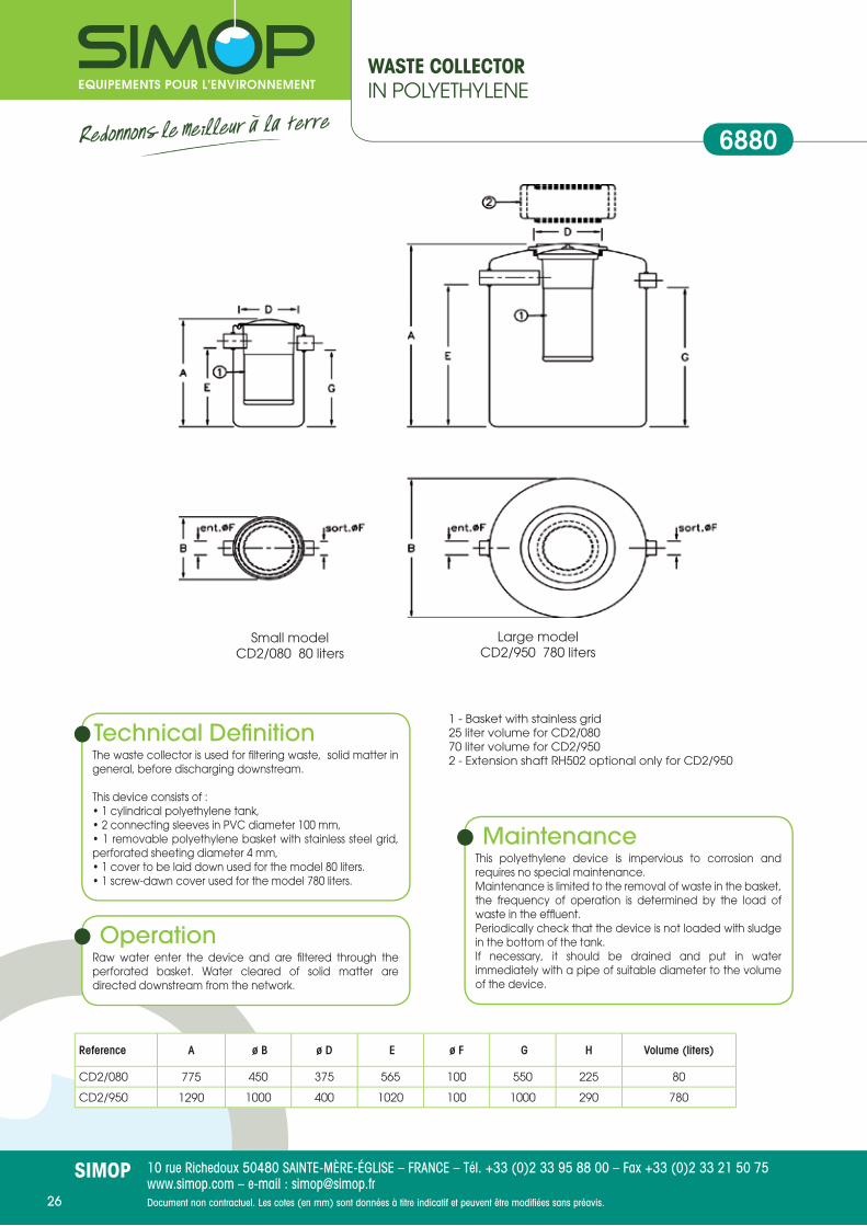
Small modelCD2/080 80 liters
Large modelCD2/950 780 liters
1 - Basket with stainless grid25 liter volume for CD2/08070 liter volume for CD2/9502 - Extension shaft RH502 optional only for CD2/950
WAST E COLLECTOR IN POLYETHYLENE
6880
Technical Defi nitionThe waste collector is used for fi ltering waste, solid matter in general, before discharging downstream.
This device consists of :• 1 cylindrical polyethylene tank,• 2 connecting sleeves in PVC diameter 100 mm,• 1 removable polyethylene basket with stainless steel grid, perforated sheeting diameter 4 mm,• 1 cover to be laid down used for the model 80 liters.• 1 screw-dawn cover used for the model 780 liters.
OperationRaw water enter the device and are fi ltered through the perforated basket. Water cleared of solid matter are directed downstream from the network.
MaintenanceThis polyethylene device is impervious to corrosion and requires no special maintenance.Maintenance is limited to the removal of waste in the basket, the frequency of operation is determined by the load of waste in the effl uent.Periodically check that the device is not loaded with sludge in the bottom of the tank.If necessary, it should be drained and put in water immediately with a pipe of suitable diameter to the volume of the device.
Reference A ø B ø D E ø F G H Volume (liters)
CD2/080 775 450 375 565 100 550 225 80
CD2/950 1290 1000 400 1020 100 1000 290 780

10 rue Richedoux 50480 SAINTE-MÈRE-ÉGLISE – FRANCE – Tél. +33 (0)2 33 95 88 00 – Fax +33 (0)2 33 21 50 75www.simop.com – e-mail : [email protected] non contractuel. Les cotes (en mm) sont données à titre indicatif et peuvent être modifi ées sans préavis.
SIMOP27
1 - Polyethylene basket with stainless steel grid2 - Crushed marble3 - Screw-dawn cover Ø 4004 - Screw-on extension shaft RH502 or RH 505 Option
NEUTRALIZING FILTERFOR BATTERY ACIDS IN POLYETHYLENE
6890
Technical Defi nitiona neutralizing fi lter in polyethylene is a device designed to neutralize the battery acids (H2S04) which can be discharged into the network following the cleaning of a storage area or an accidental spillage.
Features :• the tank is made of high density polyethylene• The basket is made of polyethylene with stainless steel grid• The lifting handle of the basket is made of galvanized steel• Fittings are made of PVC• The screw-dawn cover of diameter 400 is in polyethylene• Crushed marble - 75 kg for FN2/500 - 100 kg for FN2/950
OperationThe water containing acids enters the device through the tap nozzle. Heavy matter settle to the bottom. The effl uent charge with acids passes through the layer of marble and go out of the device. The acid neutralizes consuming marble.
MaintenanceThis polyethylene device is impervious to corrosion. It does not require any special maintenance. The marble must be completed regularly as it is consumed by the acid. Every six months, the unit must be completely drained and cleaned. Fill with clean water after drainage with a pipe whom diameter is suitable to the volume of the device.
Options :MAB05 Crushed marble, bag of 25 kgRH502 Polyethylene screw-on extension shaft Ø 400 height 250 mmRH505 Polyethylene screw-on extension shaft Ø 400 height 500 mm
Reference A ø B ø D E ø F G H Volume (liters)
FN2/500 1085 790 400 815 100 795 290 390
FN2/950 1290 1000 400 1020 100 1000 290 780

10 rue Richedoux 50480 SAINTE-MÈRE-ÉGLISE – FRANCE – Tél. +33 (0)2 33 95 88 00 – Fax +33 (0)2 33 21 50 75www.simop.com – e-mail : [email protected] non contractuel. Les cotes (en mm) sont données à titre indicatif et peuvent être modifi ées sans préavis.
SIMOP28
UseThis alarm system detects the grease level on the surface in the separator so that it is drained.
InstallationRefer to the Installation instructions P105.An Installation and user manual is delivered with the alarm.The maximum length of the sensor cable is 200 m.All connections must be made by a professional, assistance may be offered as an option.
MaintenanceThe sensors can be exposed to harsh environments. it is recommended to inspect and clean them regularly.The maintenance of the pieces of the control unit may not be performed by the user. For any repair, please contact us.
OperationThe control unit can control up to 3 sensors (grease, sludge and overfl ow). The unit controls the connected sensors every 30 minutes (adjustable frequency). The current status is dis-played on the liquid crystal 2X16 LCD screen located on the front of the unit.Grease detection is made by conductivity, water acts as a conductor while greases act as insulators.The sensor consists of two stainless steel parts, when one part is immersed in the greases, a signal is sent to the control box which triggers the alarm.A central alarm signal or any external alarm device can also be connected to the relay.
CharacteristicsAmbient temperature : -20 °C to 50 °C3 sensor inputsSupply voltage : 230 VAC +/-10 %Relay outlet : 230 Vac, 3 AProtection : IP65Length of sensor cable : 5 m
Reference For devices with the following technical sheets Cable length
ANG2-3 in PE : 6612, 6616, 6630 et 6634 10 ml
ANG2-3 in PE : 6614 et 6615 sensor 5 ml + 10 ml (with connector)
ANG2-4 in PE : 6611 et 6620 sensor 5 ml + 10 ml (with connector)
ANG3-4 in GRP : 6622, 6632 et 6635 sensor 5 ml + 10 ml (with connector)
OPTION : LEVEL ALARMFOR GREASE SEPARATORS
6682
Options :
SNB/14220 Sensor detecting the sludge level
CR-ANH Extension cable, instrumentation type
MR-ANH Connector for cable extension
SNB/SG Grease or sludge sensor

10 rue Richedoux 50480 SAINTE-MÈRE-ÉGLISE – FRANCE – Tél. +33 (0)2 33 95 88 00 – Fax +33 (0)2 33 21 50 75www.simop.com – e-mail : [email protected] non contractuel. Les cotes (en mm) sont données à titre indicatif et peuvent être modifi ées sans préavis.
SIMOP29
RH 502
RH 602
OPTION : EXTENSION SHAFTS AND FRAMES
6678RHX
Reference RH 502 RH 505 RH 602
A 250 500 250
B 600 600 760
D 400 400 600
Extension shaft RH602
To determine the product code, you must :
1 Separator type ReferenceBIX BI
BIXAT AICNX CN
CNXAT CA
Important: Regular maintenance of this equipment according to EN 1825-2 is required.See installation instructions of steel grease separators.
2 The size : The sizes : 1, 2, 3, 4, 5, 6, 7, 8, 9, 10.
3 The box material : The box is made of stainless steel : X
5 The extension shaft material :For a water level over standard water level, the device requires a stainless steel extension shaft : X
6 The covers charge :Depending on the location of the device, 15 kN : 0 125 kN : B 250 kN : C 400 kN : D
4 The water level :Set the height of outlet water level 50The water level is the height in cm between the fi nished ground and the lower cone of the outlet cuff of each device.
The product code would be :1 2 3 4 5 6
CA 05 X 050 X C
Technical Defi nition• Extension shafts made of stainless steel 304L (EN 1.4307)• Frames made of stainless steel or cast iron 15 kN, 125 kN,• 250 kN, 400 kN (with the frame)• All heights are possible, according to the most common
water levels from 500 to 1200 mmEN858-1EN 1825-1
Defi nitionExtension shafts in polyethylene high-density. Used for instal-ling the frame at the ground level when the device is buried and is providing frost protection.

10 rue Richedoux 50480 SAINTE-MÈRE-ÉGLISE – FRANCE – Tél. +33 (0)2 33 95 88 00 – Fax +33 (0)2 33 21 50 75www.simop.com – e-mail : [email protected] non contractuel. Les cotes (en mm) sont données à titre indicatif et peuvent être modifi ées sans préavis.
SIMOP30
REQuEST QuESTIONNAIRE FOR GREASE SEPARATORTo photocopy, complete and send us back :
by post : 10 rue Richedoux – 50480 Sainte Mère Église
or by fax : + 33 (0) 2 33 21 50 75
or by email : [email protected]
YOuR DETAILS
M. MS.
Surname : ..................................................... Name : ..............................................................................................................................
Position : ......................................................... Company: .......................................................................................................................
Address: ......................................................................................................................................................................................................
Zip Code: ....................................................... City : ..................................................................................................................................
Tel. : ................................................................. . Fax : ................................................................ e-mail : ....................................................
FOR COLLECTIVE KITCHENS
TYPE OF PREMISES : Restaurant 1 service Restaurant 2 services Hotel
Hospital Refectory : heated kitchen Refectory : Prepared Food
Number of meals served per day : ..........................................................................................................................................................
Using a potato peeler : Yes No
If yes, amount of potatoes (kg) per day : .................................................................................................................
FOR FOOD PROCESSING INDuSTRIES
Use of detergents: Never Occasionally
Always Special case (ex : hospital)
Average density of grease : < 0,94 > 0,94 Undetermined
Temperature of the water to be treated (in °C) : < 60°C > 60°C Undetermined
Annual water consumption used for the preparation of products (m3) : .........................................................................................
Number of days worked per year : ........................................................................................................................................................
Average daily operating time (in hours) :
FOR BuTCHER / DELI / SLAuGHTER HOuSE
Number of animals per week : ................................................................................................................
Type of animal : Cattle Pork Other
Animal products per day (kg) : ................................................................................................................
FOR BAKERY / PASTRY
Oilseed products used per day (kg) : Oil : ......................... Butter : ................. Margarine : ...........
FOR FISHMONGERS
Amount of fi sh processed per day (kg) : .................................................................................................................................................
COMMENTARIES
......................................................................................................................................................................................................................
......................................................................................................................................................................................................................
......................................................................................................................................................................................................................
......................................................................................................................................................................................................................
QuESTIONNAIRE

10 rue Richedoux 50480 SAINTE-MÈRE-ÉGLISE – FRANCE – Tél. +33 (0)2 33 95 88 00 – Fax +33 (0)2 33 21 50 75www.simop.com – e-mail : [email protected] non contractuel. Les cotes (en mm) sont données à titre indicatif et peuvent être modifi ées sans préavis.
SIMOP31
QuESTIONNAIRE INSTALLATION INSTRUCTIONSPRE TREATMENT DEVICES IN POLYETHYLENEFOR GREASE SEPARATORS
P041
STABILIZED GROuND - NOT HYDROMORPHOuS - GROuND WITH NO WATER TABLE
The device must be buried as close as possible to the place to be treated and outside a building.The cover must reach the ground level.
1) Carry out the earthwork and overlap the bottom of the excavation with some thick compacted sand (10 cm minimum) which will be led perfectly level.2) Put the device in place connecting the levels of the pipes.3) Backfi ll with sand and fi ll the device with water. Before fi lling with water, install a sheath up to the packing box and install the sensor as indicated in notice P083 (oil separators) and notice P086 (grease separators). Be careful : the minimum diameter of the sheath is 80 mm.4) Vent pipes must be connected with a recommended PVC pipe diameter 100 mm which will be capped with a device to prevent the passage of small animals.5) Finish backfi lling up to the cover with sand or topsoil only.
A slab protection resting on undisturbed ground is necessary in the following cases :- If the inlet level from the ground level is above 50 cm.- If vehicles will drive over the area less than 3 meters away- in case of cast iron covers.
Note: Put in place extension shafts to let access to the device.
INSTALLATION WITH PE RECTANGuLAR FRAME (TOTAL ACCESSIBILITY) INSTALLATION WITH PE MANHOLE COVER (CAST IRON COVER)

10 rue Richedoux 50480 SAINTE-MÈRE-ÉGLISE – FRANCE – Tél. +33 (0)2 33 95 88 00 – Fax +33 (0)2 33 21 50 75www.simop.com – e-mail : [email protected] non contractuel. Les cotes (en mm) sont données à titre indicatif et peuvent être modifi ées sans préavis.
SIMOP32
INSTALLATION INSTRUCTIONSPRE-TREATMENT DEVICES IN POLYETHYLENEGROUND WITH NO WATER TABLE OR NOT HYDROMORPHOUS GROUND
P045
Lit de sable
Dalle béton si la hauteur est supérieure
à 400mm
Sable
Dalle porteuse en béton armé
Terrain nonremué
E S
Réhausse RH602
Compactage hydrauliquede la 1ère couche de sable
IMPLANTATION SOUS ESPACES VERTS
sable
Dalle porteuse en béton armé
terrain nonremué
E S
Tampon fonte hydraulique posé sur réhausse béton prenant appui sur dalle porteuse
Rehausse RH602 (coffrage)
Lit de sable
Compactage hydrauliquede la 1ère couche de sable
IMPLANTATION SOUS PASSAGE DE VEHICULES
INSTALLATION ON NON HYDROMORPHOuS STABILIZED GROuND
Refer to standard NF EN 1825-2 for grease separators. This product is not intended to be installed in the presence of groundwater. For handling, sling the device using the two lifting lugs.
1) Carry out the earthwork.
2) Overlap the bottom of the excavation with some thick compacted sand (10 cm minimum) which wil be laid perfectly level and well compacted before placing the device.
3) Put the device in place connecting the inlet and outlet pipes.
4) When setting up an alarm, before fi lling with water, install a sensor as indicated in the P105 sheet. Provide a sheath Ø 63 behind the cable gland.
5) Fill in partially with clear water to a height of 50 cm from the bottom of the device.
6) Backfi ll with a fi rst layer of peripheral sand to a height of 50 cm and water the sand to obtain a hydraulic compaction.
7) Finish backfi lling up to the cover, symmetrically in successive layers, only with sand.
8) If the device is installed on green areas with no vehicle passing, it is possible to raise the cover using only polyethylene extension shafts. If there is backfi ll in excess of 40 cm, a self-supporting armoured concrete slab is to be laid just above the tank’s upper cone at the level of the extension shaft. This slab must be built on a non-turned ground.
9) If vehicles will drive over the area, it is necessary to pour a self-supporting armoured concrete slab just above the tank’s upper cone at the level of the extension shaft. This slab must be built on a non-turned ground. It will be necessary to adjust the height with a concrete extension shaft which will be built on the self-supporting concrete slab.
INSTALLATION ON GREEN AREAS
INSTALLATION ON PLACEWITH VEHICLE PASSING
10 rue Richedoux 50480 SAINTE-MÈRE-ÉGLISE – FRANCE – Tél. +33 (0)2 33 95 88 00 – Fax +33 (0)2 33 21 50 75www.simop.com – e-mail : [email protected] non contractuel. Les cotes (en mm) sont données à titre indicatif et peuvent être modifi ées sans préavis.
SIMOP33
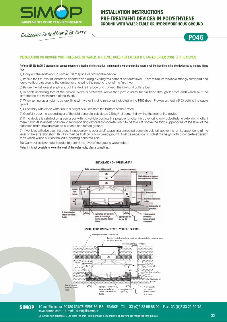
INSTALLATION INSTRUCTIONSPRE-TREATMENT DEVICES IN POLYETHYLENEGROUND WITH WATER TABLE OR HYDROMORPHOUS GROUND
P046
INSTALLATION ON GROuND WITH PRESENCE OF WATER, THE LEVEL DOES NOT EXCEED THE TAN’KS uPPER CONE OF THE DEVICE.
Refer to NF EN 1825-2 standard for grease separators. During the installation, maintain the water under the invert level. For handling, sling the device using the two lifting lugs.
1) Carry out the earthwork to obtain 0.50 m space all around the device.
2) Realise the fi rst layer of reinforced concrete slab using a 350 kg/m3 cement perfectly level, 15 cm minimum thickness, strongly scrapped and leave vertical pins around the device for anchoring the second layer of the fl uid invert.
3) Before the fi rst layer strenghtens, put the device in place and connect the inlet and outlet pipes
4) In each anchoring foot of the device, place a protective sleeve then pass a metal tor pin bend through the two ends which must be attached to the main frame of the invert.
5) When setting up an alarm, before fi lling with water, install a sensor as indicated in the P105 sheet. Provide a sheath Ø 63 behind the cable gland.
6) Fill partially with clean water up to a height of 50 cm from the bottom of the device.
7) Carefully pour the second layer of the fl uid concrete slab dosed 350 kg/m3 cement drowning the feet of the device.
8) If the device is installed on green areas with no vehicle passing, it is possible to raise the cover using only polyethylene extension shafts. If there is backfi ll in excess of 40 cm, a self-supporting armoured concrete slab is to be laid just above the tank’s upper cone at the level of the extension shaft. This slab must be built on a non-turned ground.
9) If vehicles will drive over the area, it is necessary to pour a self-supporting armoured concrete slab just above the tan’ks upper cone at the level of the extension shaft. This slab must be built on a non-turned ground. It will be necessary to adjust the height with a concrete extension shaft which will be built on the self-supporting concrete slab.
10) Carry out a piezometer in order to control the level of the ground water table.
Note: If it is not possible to lower the level of the water table, please consult us.
1 ère couche du radier béton dressé à la règle
épingles en fer tor 6 pour accrochage 2ème couche béton fluide
2 ème couche radier en béton fluide
Dalle porteuse en béton armé
E S
épingle en fer tor de 12
500 500
H
terrain non
remué
Remblai latéral en sable
Piézomètre
Géotextile et graviers
IMPLANTATION SOUS PASSAGE DE VEHICULES
Tampon fonte hydraulique posé sur réhausse béton prenant appui sur dalle porteuse
Rehausse RH602 (coffrage)
INSTALLATION ON GREEN AREAS
INSTALLATION ON PLACE WITH VEHICLE PASSING

10 rue Richedoux 50480 SAINTE-MÈRE-ÉGLISE – FRANCE – Tél. +33 (0)2 33 95 88 00 – Fax +33 (0)2 33 21 50 75www.simop.com – e-mail : [email protected] non contractuel. Les cotes (en mm) sont données à titre indicatif et peuvent être modifi ées sans préavis.
SIMOP34
INSTALLATION INSTRUCTIONS FOR UNDERGROUND HORIZONTAL GRP TANKS (EXCEPT STORAGE TANKS) ON HORIZONTAL, STABILIZED, NON FLOODED GROUND AND GROUND WITH NO WATER TABLE
P064
INSTALLATION ON STABILIZED AND NON HYDROMORPHOuS GROuND
For handling, sling the device using the two lifting lugs.
1) Carry out the earthwork.
2) Overlap the bottom of the excavation with some thick compacted sand (10 cm minimum) which wil be laid perfectly level and well compacted before placing the device.
3) Put the device in place connecting the inlet and outlet pipes.
4) When setting up an alarm, before fi lling with water, install a sensor as indicated in the P105 sheet. Provide a sheath Ø 63 behind the cable gland.
5) Fill in partially with clear water to a height of 50 cm from the bottom of the device.
6) Backfi ll with a fi rst layer of peripheral sand to a height of 50 cm and water the sand to obtain a hydraulic compaction.
7) Finish backfi lling up to the cover, symmetrically in successive layers, only with sand.
8) For devices with manhole covers or if the device is installed on green areas with no vehicle passing, it is possible to raise the cover using only polyethylene extension shafts. If there is backfi ll in excess of 50 cm, a self-supporting armoured concrete slab is to be laid just above the tank’s upper cone at the level of the extension shaft. This slab must be built on a non-turned ground.
9) For devices with manhole covers, or if vehicles will drive over the area less than 4 meters away, or in case of temporary overloads due to extreme weather conditions, it is necessary to pour a self-supporting armoured concrete slab just above the tank’s upper cone at the level of the extension shaft. This slab must be built on a non-turned ground. It will be necessary to adjust the height with a concrete extension shaft which will be built on the self-supporting concrete slab. The extension shaft will be wearing an odour tight frame.
INSTALLATION ON GREEN AREAS INSTALLATION ON PLACE WITH VEHICLE PASSING
Aeration Ø 100 (ventilation spur on manhole) should be provided to evacuate gases as high as possible above the ridge. It will wearing a device to prevent the passage of insects and small animals.
Tampon fonte posé sur réhausse béton prenant appui sur dalle porteuse
sable
Lit de sable
IMPLANTATION SOUS PASSAGE DE VEHICULES
Remblai
Terrainnon remué
Dalle porteuse en béton armé
Compactage hydrauliquede la 1ère couche de
sable
Dalle porteuse en béton armé
Réhausse RH602
Dalle béton si la hauteur est
supérieure à 500mm
Lit de sable
IMPLANTATION SOUS ESPACES VERTS
Terrainnon remué
sable
Compactagehydrauliquede la 1ère couche de
sable

10 rue Richedoux 50480 SAINTE-MÈRE-ÉGLISE – FRANCE – Tél. +33 (0)2 33 95 88 00 – Fax +33 (0)2 33 21 50 75www.simop.com – e-mail : [email protected] non contractuel. Les cotes (en mm) sont données à titre indicatif et peuvent être modifi ées sans préavis.
SIMOP35
INSTALLATION INSTRUCTIONS PRETREATMENT DEVICES IN GRPØ 1300 AND Ø 1600HYDROMORPHOUS OR GROUND WITH A WATER TABLE
P065
INSTALLATION ON GROuND WITH PRESENCE OF WATER, THE LEVEL DOES NOT EXCEED THE TAN’KS uPPER CONE OF THE DEVICE
This device is designed to withstand a ground water table whom the level does not exceed the upper generatrix of the device ferrule. During the installation, maintain the water under the invert level. For handling, sling the device using the two lifting lugs.
1) Carry out the earthwork to obtain 0.50 m space all around the device.
2) Realise a reinforced concrete slab using a 350 kg/m3 cement perfectly level, 15 cm minimum thickness, strongly scrapped and leave pins awaiting for the anchoring straps.
3) Once the invert is done, Overlap the bottom of the excavation with some thick compacted sand (10 cm minimum) which wil be laid perfectly level and well compacted before placing the device. Put the device in place connecting the inlet and outlet pipes.
4) Place the anchoring straps.
5) When setting up an alarm, before fi lling with water, install a sensor as indicated in the P105 sheet. Provide a sheath Ø 63 behind the cable gland.
6) Fill in partially with clear water to a height of 50 cm from the bottom of the device.
7) Backfi ll with a fi rst layer of peripheral sand to a height of 50 cm and water the sand to obtain a hydraulic compaction.
8) Finish backfi lling up to the cover, symmetrically in successive layers, only with sand.
9) For devices with manhole covers or if the device is installed on green areas with no vehicle passing, it is possible to raise the cover using only polyethylene extension shafts. If there is backfi ll in excess of 50 cm, a self-supporting armoured concrete slab is to be laid just above the tank’s upper cone at the level of the extension shaft. This slab must be built on a non-turned ground.
10) For devices with manhole covers, or if vehicles will drive over the area less than 4 meters away, or in case of temporary overloads due to extreme weather conditions, it is necessary to pour a self-supporting armoured concrete slab just above the tank’s upper cone at the level of the extension shaft. This slab must be built on a non-turned ground. It will be necessary to adjust the height with a concrete extension shaft which will be built on the self-supporting concrete slab. The extension shaft will be wearing an odour tight frame.
INSTALLATION ON GREEN AREAS INSTALLATION ON PLACE WITH VEHICLE PASSING
Aeration Ø 100 (ventilation spur on manhole) should be provided to evacuate gases as high as possible above the ridge. It will wearing a device to prevent the passage of insects and small animals.
Terrain
non remué
sable
Compactage
hydraulique
de la 1ère
couche de
sable
Radier béton
armé
Ceinture
d'ancrage
Tampon fonte posé sur réhausse béton prenant
appui sur dalle porteuse
IMPLANTATION SOUS PASSAGE DE VEHICULES
Lit de sable
(200mm)
Remblai
Dalle porteuse en béton armé
Winch à
spitter
Dalle porteuse en béton armé
Réhausse RH602
Dalle béton
si hauteur >
à 500mm
IMPLANTATION SOUS ESPACES VERTS
Terrain
non remué
sable
Compactage
hydraulique
de la 1ère
couche de
sable
Lit de sable
(200mm)Radier béton
armé
Ceinture
d'ancrage
Winch à
spitter

10 rue Richedoux 50480 SAINTE-MÈRE-ÉGLISE – FRANCE – Tél. +33 (0)2 33 95 88 00 – Fax +33 (0)2 33 21 50 75www.simop.com – e-mail : [email protected] non contractuel. Les cotes (en mm) sont données à titre indicatif et peuvent être modifi ées sans préavis.
SIMOP36
10 rue Richedoux 50480 SAINTE-MÈRE-ÉGLISE – FRANCE – Tél. +33 (0)2 33 95 88 00 – Fax +33 (0)2 33 21 50 75www.simop.com – e-mail : [email protected] non contractuel. Les cotes (en mm) sont données à titre indicatif et peuvent être modifi ées sans préavis.
SIMOP36
10 rue Richedoux 50480 SAINTE-MÈRE-ÉGLISE – FRANCE – Tél. +33 (0)2 33 95 88 00 – Fax +33 (0)2 33 21 50 75www.simop.com – e-mail : [email protected] non contractuel. Les cotes (en mm) sont données à titre indicatif et peuvent être modifi ées sans préavis.
10 rue Richedoux 50480 SAINTE-MÈRE-ÉGLISE – FRANCE – Tél. +33 (0)2 33 95 88 00 – Fax +33 (0)2 33 21 50 75www.simop.com – e-mail : [email protected]
SIMOP
NOTES


Mise
en
page
s Qu
ai d
es G
raph
’ – J
uille
t 201
2.
Distributed by:
10 rue Richedoux50480 SAINTE-MÈRE-ÉGLISE
FRANCETel. +33 (0)2 33 95 88 00 Fax +33 (0)2 33 21 50 75
www.simop.com e-mail : [email protected]
S.A.S. CAPITAL 1 525 000 eurosSIRET 304 971 641 00085
Certifi é ISO 9001
Rainwater treatment• Rainwater Recovery• Oil Separators• Particulate Decanters• Basin Facilities
Wastewater treatment• On-site Sanitation < 20 IE• On-site Sanitation > 20 IE• Grease Separators
Roads & Networks• Soil Products• Road Equipments• Sanitation Manholes• Pumping Stations
Find all our products on
www.simop.com
SIMOP IS ALSO


