Page 1
Original Publication October 2012 1 of 34
Division of Engineering/Detailed Specifications/Standards & Specs/MCPW Manuals/Manual 5
Manual 5
MANUAL 5 - WASTEWATER PUMPING STATIONS & FORCE MAINS
5.01 Pre Design Requirements
In situations where gravity flow to an existing sewer is not feasible, MCPW will consider
the installation of a wastewater pumping station and a force main. Certain factors must
be addressed by the developer for the project for consideration by MCPW. The factors
include:
1. Determine the wastewater flow that would be generated by the total built-out of the
natural drainage basin based upon the existing zoning. Pumps shall be sized for a
minimum of 20 years or as approved by the County Engineer.
2. Evaluate the capacity of the receiving sewer main at the point of discharge and down-
stream facilities to determine that sufficient capacity is available for the transferred
sewer flow.
5.02 Pump & Site Design, General
A. Pump Station
1. Pump stations shall be designed to contain raw wastewater.
2. Pump station structures shall be designed to withstand the hydrostatic forces that
they will be subjected to, including uplift.
3. Pump stations shall be of the Enclosed Above Grade Self-Priming Package-Type
or Submergible type as approved by the Engineer.
4. All stations shall have a minimum of two (2) pumps of equal capacity, with each
pump sized to handle design flow, and shall be capable of handling flows in
excess of the expected peak flow. Where three or more pumps are required, they
shall be of such capacity that with any one unit out of service, the remaining units
will have capacity to handle peak sewage flows, per NCDENR minimum
guidelines. Where pumping stations may be designed to handle larger future
flows, the wet well, piping, electrical equipment, etc. shall be sized to
accommodate the future flow.
5. Where a pumping station is sized to accommodate growth and will operate at less
than 25% of its capacity, chemical feed facilities shall be provided for odor and
corrosion control. These facilities shall include all feed equipment and storage
Page 2
Original Publication October 2012 2 of 34
Division of Engineering/Detailed Specifications/Standards & Specs/MCPW Manuals/Manual 5
facilities, including secondary containment and shall be approved in advance by
the Engineer.
6. A receiving manhole, separate from the wet well, shall be provided within 20 feet
of the Wet-Well. This receiving manhole shall have a rim elevation one foot
minimum below the Wet-Well rim and two feet above the 100 year flood
elevation. Where multiple sewers converge at a pumping station, they shall be
brought together at the receiving manhole and only one influent line shall enter
the wet well. This manhole shall be situated to facilitate future upstream
extensions of the gravity sewer.
7. Pumping station piping shall be sized to maintain flow velocities between 2.5 and
5.0 fps. The minimum size force main shall be 4" diameter.
8. Wastewater pumping stations, access drains, structures, electrical equipment, etc.
shall be protected from physical damage by sitting no less than 3 feet above the
predicted 100 year flood water elevation. Stations shall remain fully operational
and accessible during the 100-year flood. The predicted 100-year flood elevation
shall be shown on all site plans. The final station elevation shall be indicated on
the record drawings. The 100-year flood elevation shall be converted to the same
datum used for the station design.
9. Wet well and Electrical Service shall be designed for built-out conditions.
B. Site Work
1. The site work shall be generally level graded to remove runoff from site in a non-
erosive manner. Drainage swales shall be provided to direct drainage away from
the site.
2. The site shall be stabilized inside the fence and one foot around the outside
perimeter with ABC stone 6" thick. A landscaped buffer shall be constructed
outside of the fence to screen the station from adjoining properties. The proposed
landscaping shall be shown on the approved plans. All proposed landscaping
shall be of species suited to the climate region and require minimal maintenance.
(2" tree trunk, 3 gallon shrub etc,)
3. An all-weather access road constructed of 6" minimum of compacted aggregate
base course and located within a 25-foot minimum access easement shall be
provided to the pumping station site. The road shall be a minimum of 15 feet
minimum in width, with shoulders, side ditches and cross drainage as needed. A
turn around area large enough for a fuel oil truck (NCDOT-SU design vehicle)
shall be provided outside of the pump station fence. The maximum roadway
grade shall be 8 percent for stone base roadways. Steeper roads shall be paved.
Pavement shall be Concrete or Asphalt. The roadway shall be (1) foot above the
100 year base flood elevation.
Page 3
Original Publication October 2012 3 of 34
Division of Engineering/Detailed Specifications/Standards & Specs/MCPW Manuals/Manual 5
4. Suction and discharge piping shall be ductile iron pipe designed and
manufactured per ANSI/AWWA C150/A21.15-05. The pipe shall have protective
interior coating a minimum of 40 mil equivalent to "Protecto 401" by American
Cast Iron Pipe.
C. Emergency Pump Connection
Pump Stations shall be equipped with an Emergency Pump Connection fastened to
the outlet line from the Valve Vault. The connection shall have a plug valve, an
emergency pump connection approximately 2 feet above the ground and with a 90
degree flanged connection parallel to the ground's surface. A Baver quick connect
and blind flange with stainless steel bolts shall be provided. All pipe shall be DIP
and there shall be a 4 inch concrete pad surrounding the connection and plug valve.
(See STD. No. PS 1)
D. Yard Hydrant
Each pumping station shall have a potable water supply service line consisting of a 1"
service line with an Engineer approved RPZ-type backflow preventer and terminating
at the pump station site with a freeze-proof yard hydrant. An insulated and heated
enclosure shall be provided to protect the RPZ from freezing. (See STD. No. PS 2)
The Yard Hydrant to be Simmons Sanitary Yard Hydrant, 802LF 54" or equal.
E. Fencing
All pumping station sites shall be fenced for security. Pumping stations located in
remote areas shall have a chain link fence as described below. (See STD No. PS 3)
Stations that are adjacent (visible) to residential and commercial areas shall have a
wooden shadow box style fence.
(1) Wooden Fencing
Where a wooden fence is provided around the pumping station site, the fence
shall have the following features:
Height: 6-½’ to top of pickets
Gates: 1 – 12’ double-leaf vehicle gate
1 – 4’ single-leaf personnel gate
The fence shall be of the shadow box style (80% opaque), with vertical pickets
(alternating inside and out), constructed entirely of pressure treated lumber with
galvanized hardware and fasteners.
(a) Vertical Pickets - shall be 5/4" by 6" by 6' nominal dimension treated lum-
ber
Page 4
Original Publication October 2012 4 of 34
Division of Engineering/Detailed Specifications/Standards & Specs/MCPW Manuals/Manual 5
(b) Posts - shall be 6" by 6" by 10' nominal dimension treated lumber, with
the tops beveled at a 45-degree angle each way (pyramid top)
(c) Horizontal Rails - shall be 2" by 4" by 7'-6" nominal dimension treated
lumber, three per panel section
Posts shall be set at 8' centers, maximum, at each corner and at each side of each gate.
All posts shall be set 36" deep in concrete. Horizontal rails shall be set 12", 42" and
72" above grade. Pickets shall be attached to the horizontal rails with the bottoms 6"
above grade and alternating inside and out. All lumber shall be pressure treated
Southern Yellow Pine and bear the mark of the American Wood Preservers
Association Standard No. C2/C9.
All gates shall be equipped with lockable latches and tamper proof hinges. For
vehicle gates, keepers shall be provided to hold gates in the open position.
(2) Chain Link Fencing
Where a chain link fence is provided around the pumping station site, the fence
shall have the following features:
Height: 6’ to center of top rail
Barbed Wire: 3 strands at top
Gates: 1 – 12’ double-leaf vehicle gate
1 – 4’ single-leaf personnel gate
All fencing materials shall be vinyl coated galvanized steel, green or black in color.
The fencing materials shall be as follows:
(1) Vinyl Coated Chain Link Fence - woven 2-inch mesh of No. 9 ga. (0.1483
in.) copper bearing steel wire, 72 inches wide, galvanized after fabrication.
Minimum tensile strength of wire shall be 90,000 psi. The top edge shall
be barbed.
(2) Steel Line Posts - line posts shall be 2½" OD vinyl coated galvanized steel
pipe weighing 3.65 lbs per lineal foot.
(3) Steel Top Rails - the top rails shall be 1-5/8" OD vinyl coated galvanized
pipe weighing 2.27 lbs per lineal foot, with expansion couplings of outside
sleeve type. Rails shall be continuous for outside sleeve type for full
length of fence.
Page 5
Original Publication October 2012 5 of 34
Division of Engineering/Detailed Specifications/Standards & Specs/MCPW Manuals/Manual 5
(4) Steel Terminal, End, Corner & Pull Posts - (referred to herein as terminal
posts) - 3" OD vinyl coated galvanized steel pipe weighing not less than
5.79 lbs per lineal foot. Posts shall be of sufficient length to permit the
bottom 36 inches to be set in concrete.
(5) Bracing for Use Between Terminal, End, Corner, Gate & Pull Posts and
First Adjacent Line Posts - 1-5/8" OD vinyl coated galvanized steel pipe
weighing not less than 2.27 lbs per lineal foot.
(6) Gate Posts - 4" OD vinyl coated galvanized steel pipe weighing 9.11 lbs
per lineal foot.
(7) Tension Bars – 3/16" X ¾" minimal steel, vinyl coated galvanized and
one-piece for full height of fabric.
(8) Stretcher Bar Bands - steel, wrought iron, or malleable iron (painted or
vinyl coated) to secure stretcher bars to terminal, end, pull, corner and gate
posts. Space not over 12-inch on center.
(9) Gate Frames - 2" OD vinyl coated galvanized steel pipe weighing not less
than 2.72 per lineal foot. A 12’ double swing gate (two 6’0" leaves) and a
4’ single-swing gate shall be provided.
(10) Gate Hardware:
Hinges - pressed or forged steel or malleable iron to suit gate size, or non-
lift-off heavy duty type, offset to permit 180º gate opening.
Latches - provide latching devices, lockable with padlock from either side.
Latches for double gates with automatic engaging latch on one leaf and
drop rod type latch on the other leaf. Furnish drop rod complete with suit-
able casting set in concrete to hold gate leaf in place when drop rod is
engaged.
Keepers - provide keepers for all gates to automatically engage gate leaf
and hold it in open position until manually released.
(11) Anchorage - line posts, gate posts and corner posts shall be set in con-
crete 36" deep X 12" dia. (minimum). Concrete shall have a minimum
compressive strength of 3,000 psi at 28 days.
(12) Combination Post Top Cap & Barbed Wire Supporting Arm - steel,
wrought or malleable iron complete with provisions for anchorage to posts
and attaching 3 rows of barbed wire. Provide one cap and vertical arm for
each post where barbed wire is required.
Page 6
Original Publication October 2012 6 of 34
Division of Engineering/Detailed Specifications/Standards & Specs/MCPW Manuals/Manual 5
(13) Barbed Wire - vinyl coated galvanized two (2) strand, 12-½ ga. wire with
14 ga. 4-point barbs spaced 5 in. oc.
(14) Miscellaneous Items & Materials - Line posts shall be spaced at a
maximum interval of 10 feet.
Top rails shall be installed with expansion couplings at intervals of not more than
20 feet and shall be attached to the posts with appropriate wrought iron fittings.
Bracing assemblies shall be installed on all terminal posts, gate posts and at both
sides of corner posts and pull posts. Diagonal tension members shall not be less than
3/8" diameter, with a tension take-up device, and shall extend from compression
member to base of posts. Posts shall be plumb when diagonal rod is under the correct
tension.
Gate frames shall be constructed with heavy malleable iron fittings at the joints to
produce rigid joints. Bracing shall be installed so as to provide a rigid, non-sagging
or twisting gate. Gate fabric shall be the same as fence fabric and attached in a like
manner. Frames shall be furnished with three (3) strands of barb wire at the top.
5.03 Engineering/Design Requirements
A. Engineering calculations must be signed, sealed, and dated by a North Carolina
Registered Professional Engineer (PE). Such calculations shall include, at a
minimum, the following items:
1. Total dynamic head calculations for all applicable pumping stations, at low water
level and high water level.
2. System curve/pump curve analysis used to determine pump selection and
operational point.
3. If discharge elevation is lower than highpoint, provide calculations for expected
hydraulic conditions.
4. Pump station cycle and pump run times, including an evaluation of any depressed
sections of the force main to determine if the pump station is capable of
completely flushing the force main section being evaluated in a single pumping
cycle.
5. Pump station flotation/buoyancy calculations.
6. Provide re-prime calculations for suction lift stations.
7. Minimum velocity within the force main.
Page 7
Original Publication October 2012 7 of 34
Division of Engineering/Detailed Specifications/Standards & Specs/MCPW Manuals/Manual 5
8. Maximum detention times within the pump station and force main.
9. Provide Generator size calculations.
B. Downstream Sewer Evaluation demonstrating that the pump station discharge will
not overload the receiving sewer line:
1. In situations where the pump station discharges into a gravity sewer, the
downstream gravity sewer shall be evaluated based on peak flow from the
proposed project as well as peak flows already tributary to the downstream
gravity sewer.
2. In situations where the pump station discharges into another pump station, the
downstream pump station shall be evaluated to verify its ability to convey peak
flow from the proposed project as well as peak flows already tributary to the
downstream pump station.
3. In situations where the pump station discharges into a force main, the downstream
force main shall be evaluated on peak flows from the proposed project as well as
peak flows already tributary to the downstream force main. The ability of each
pump station tributary to the downstream force main to pump against additional
head created by greater flows through the force main shall also be evaluated. An
evaluation of the discharge point of the downstream force main as described
above shall also be performed.
5.04 Pump Requirements
A. General requirements
1. Only pumps designed and manufactured for use in conveying raw, unscreened
wastewater shall be acceptable.
2. Pump selection shall consider the duty requirements as well as the physical and
chemical characteristics of the wastewater being conveyed. Materials used in
pump construction shall also be suitable from the physical and chemical
characteristics of the wastewater being conveyed. Accepted submersible pump
manufactures are Fairbanks Morse, Barns or approved equal. Suction lift pump
stations shall be Gorman Rupp or approved equal.
3. Pump stations conveying residential, commercial, institutional, or industrial
domestic wastewater shall be provided with pumps that are suitable for
continuous duty in conveying raw unscreened wastewater.
Page 8
Original Publication October 2012 8 of 34
Division of Engineering/Detailed Specifications/Standards & Specs/MCPW Manuals/Manual 5
4. Pumps shall be capable of handling a three-inch solid and any trash or stringy
material that can pass through a four-inch hose unless a mechanical means of
solids reduction is installed at the pump station.
a. Pumps shall be made non-clog either by passing solids, trash, and stringy
material through a non-clog or vortex-type impeller or by grinding, chopping,
or cutting them prior to passing them through the impeller. Impellers shall
have blades that are generally forward rounded or otherwise configured to
avoid catching solids, trash, and stringy material.
b. Acceptable mechanical means of solids reduction shall include mechanical bar
screens, trash bucket or other similar devices.
5. Pump suction and discharge openings shall be no less than four inches, in diameter
unless the pump is capable of grinding, chopping, or cutting solids, or a
mechanical means of reducing the size of a three-inch solid and any trash or
stringy material that can pass thorough a four-inch hose is installed at the pump
station.
6. The power source, voltage and phasing shall be certified before ordering the
pumps.
B. Number and Capacity
1. Multiple pumps shall be used such that the pump station is capable of conveying
the peak discharge to its desired outfall location with the largest single pump out
of service.
a. In duplex pump stations; the pumps shall be of the same capacity. If pumps in
series are required, each set of pumps in series shall be viewed as a single
pumping unit.
b. Priming pumps, and other auxiliary system for pump functionality, shall be
provided in multiple numbers
c. At least one standby pump and motor shall be provided.
2. Pump capacity shall be based on wastewater flow expected to become tributary to
the station for the entire project at build out. For regional stations, capacity shall
be based on wastewater flow expected from the entire service area over the life of
the pump station.
Page 9
Original Publication October 2012 9 of 34
Division of Engineering/Detailed Specifications/Standards & Specs/MCPW Manuals/Manual 5
3. Interim sizing of pumps and associated pump stations shall be allowable, although
not for economic purposes. A statement of initial service capacity shall be on the
drawings for projects that are approved for an interim condition. Additional
wastewater flow shall not be made tributary to the station until a request for
permit modification is submitted, approved, and the pump station upgraded and
certified.
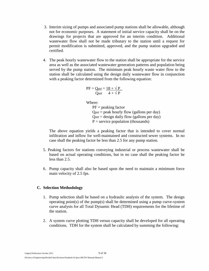
4. The peak hourly wastewater flow to the station shall be appropriate for the service
area as well as the associated wastewater generation patterns and population being
served by the pump station. The minimum peak hourly waste water flow to the
station shall be calculated using the design daily wastewater flow in conjunction
with a peaking factor determined from the following equation:
PF = Qphf = 18 + √ P_
Qddf 4 + √ P
Where:
PF = peaking factor
Qphf = peak hourly flow (gallons per day)
Qddf = design daily flow (gallons per day)
P = service population (thousands)
The above equation yields a peaking factor that is intended to cover normal
infiltration and inflow for well-maintained and constructed sewer systems. In no
case shall the peaking factor be less than 2.5 for any pump station.
5. Peaking factors for stations conveying industrial or process wastewater shall be
based on actual operating conditions, but in no case shall the peaking factor be
less than 2.5.
6. Pump capacity shall also be based upon the need to maintain a minimum force
main velocity of 2.5 fps.
C. Selection Methodology
1. Pump selection shall be based on a hydraulic analysis of the system. The design
operating point(s) of the pump(s) shall be determined using a pump curve-system
curve analysis for all Total Dynamic Head (TDH) requirements for the lifetime of
the station.
2. A system curve plotting TDH versus capacity shall be developed for all operating
conditions. TDH for the system shall be calculated by summing the following:
Page 10
Original Publication October 2012 10 of 34
Division of Engineering/Detailed Specifications/Standards & Specs/MCPW Manuals/Manual 5
a. Static head requirements for both the suction and discharge sides of the pumps
shall be evaluated including intermediate high points in the force main and the
discharge elevation.
b. Friction head requirements for the suction and discharge sides of the pumps
shall be evaluated. The friction head shall be calculated using the Hazen-
Williams formula:
hf = L x 10.44 Q 1.85
C 1.85 D 4.87
Where:
hf = friction head for pipe segment (feet)
L = length of pipe segment evaluated (feet)
Q = pumping rate (gallons per min)
C = Hazen-Williams coefficient
D = diameter of pipe segment evaluated (inches)
Conditions shall be evaluated including, multiple pump operation within the
subject force main, simultaneous pump station operation for common force
main situations and the possibility for gravity flow conditions in fore main
segments with extreme negative slopes that may not flow full.
c. Head derived from minor losses of valves and other fittings shall be evaluated.
d. If applicable, the pressure head at the junction of the existing force main shall
also be evaluated, considering the effects of simultaneous pump station
operation and multiple pump operation in other pump stations.
3. System curves shall be evaluated for present day and conditions that may exist
over the expected lifetime of the pump station.
a. The following maximum values shall be allowable for C:
Pipe type Initial Service End-of-Service C DI 125 100
PVC 140 120
HDPE 140 120
b. Friction head and minor losses shall be evaluated for initial condition and the
end-of-service condition.
c. The design operating point(s) shall be the intersection of the pump curve and
the calculated system curve(s).
Page 11
Original Publication October 2012 11 of 34
Division of Engineering/Detailed Specifications/Standards & Specs/MCPW Manuals/Manual 5
4. Pumps shall be selected such that all design-operating points are on the pump
curve as supplied by the manufacturer. Pumps shall be selected such that the net
positive suction head available (NPSHA) shall be greater than the net positive
suction head required (NPSHR) at each of the design operating points.
5. Pumps shall be selected such that the pumps will not cavitate. Freewheeling (i.e.,
operating at pump run-out) or deadheading (i.e., operating at pump shut-off) of
pumps shall not be allowed.
6. Pumps shall be selected so operating efficiency is maximized during all hydraulic
conditions over the lifetime of the pump station.
a. Consider minimizing motor speeds during the pump selection process.
b. The horsepower rating of each pump motor shall be at least 1.15 service factor
but design shall be non-overloading.
c. The selected pumps and motors shall operate at the most economical
efficiency under average daily flow conditions.
D. Cycle and Pump Run Times
1. Constant speed pumps shall be cycled such that the number of starts are
minimized and resting times are maximized to avoid overheating and
overstressing of the pump motor.
a. Automatic pump alternation shall be provided.
b. Pumps shall be designed to operate between two and eight times per hour
at design daily flow (DDF).
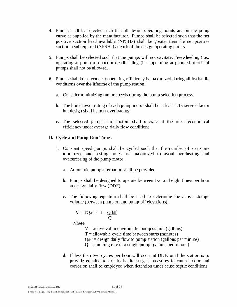
c. The following equation shall be used to determine the active storage
volume (between pump on and pump off elevations).
V = TQddf x 1 – Qddf
Q
Where:
V = active volume within the pump station (gallons)
T = allowable cycle time between starts (minutes)
Qddf = design daily flow to pump station (gallons per minute)
Q = pumping rate of a single pump (gallons per minute)
d. If less than two cycles per hour will occur at DDF, or if the station is to
provide equalization of hydraulic surges, measures to control odor and
corrosion shall be employed when detention times cause septic conditions.
Page 12
Original Publication October 2012 12 of 34
Division of Engineering/Detailed Specifications/Standards & Specs/MCPW Manuals/Manual 5
2. MCPW may allow using variable speed pumps for main pump stations or
stations that discharge into a wastewater treatment facility, only if constant
speed pumps are not applicable or practical.
3. Pump run times shall be such that excessive wear of the pumps does not
occur.
4. At DDF, adequate time shall be provided to allow a constant speed pump to
“ramp up” to full speed before the pumping cycle ends and shall not be less
than or greater than those recommended by the pump manufacturer.
5.05 Wet Well Requirements & Design
The effective capacity of the wet well should be such that it can contain the flow capacity
of the drainage basin with the required cycles of the pumps. The inflow line is to be
designed to prevent Vortex within the wet well. (For typical Section See STD. No. PS 4
and PS5)
A. Valves
1. Valves shall be suitable for use with raw, unscreened wastewater, as well as the
normal and maximum operation pressures expected at the pump station.
a. A full closing shut-off "full port plug style" valve shall be on the discharge
piping of each pump and on the suction piping of each drywell pump.
b. A check valve shall be on the discharge piping of each pump, between the
pump and shut-off valve. Check valves shall be equipped with counter
weights and/or springs to prevent water hammer and back siphoning.
c. A valve shall be provided on the suction piping between the pump and the wet
well if a potential exist for the wet well water level to rise above the pump
suction elevation in wet well, dry well applications.
d. Air release valves shall be provided in the valve vault prior to the check valve
on a submersible station and before the check valve on a suction lift station..
Discharge shall be piped into the wet well.
2. Valve Forces
a. A check valve and a gate valve shall be provided for the discharge line of each
pump. Valves shall be rated for 200 psi working pressure, and shall have full
port openings equal to 100% of the adjacent pipe area. Check valves and
shut-off valves shall be mounted in the horizontal position. Check valves
shall be swing type with outside lever and spring.
Page 13
Original Publication October 2012 13 of 34
Division of Engineering/Detailed Specifications/Standards & Specs/MCPW Manuals/Manual 5
b. All piping, couplings, fittings, valves, etc. shall be Class 125 flanges meeting
ANSI B16.1 Specifications, unless class 250 flanges are required for high
head installations. All piping shall be factory flanged. Flanged coupling
adapters, equal to Dresser Style 127, Rockwell 912, shall be provided on one
side of the check valve to allow removal and replacement.
B. Allowable Velocities
1. Suction pipe velocities shall be in the range of two (2.0) to five (5.0) feet per
second (Self priming pump suction velocity may exceed five (5.0) feet per
second), but be less than 8 fps.
2. The force main velocities of flow shall be greater than two (2.5) feet per second
but less than eight (8.0) feet per second.
C. Bypass Pumping
Connections shall be provided to allow emergency bypass pumping to occur. The
bypass pumping shall have a Baver quick connect couplings, as indicated in the
standard detail for all lift stations.
D. Pump Submergence Depth
1. Sufficient submergence of the pump or pump suction piping shall prevent
vortexing within the wet well.
2. In no case shall the all pumps-off activation level be less than the minimum level
required for successful pump operation, as recommended by the pump
manufacturer.
E. Appurtenances
1. Consideration shall be given to protecting pump station structures and equipment
from physical damage or clogging from solid material normally present in
wastewater though the use of bar screen.
Bar Screen
Where required by the County Engineer, the influent sewer shall have an open
flange connection within the wet well and have a bar screen with a clear opening
of no less than 1 inch or more than 1-3/4 inch. Manually cleaned screens should
be placed on a slope of 30 to 45 º from the horizontal. At design average flow
conditions, approach velocities should be no less than 1.25 feet per second to
prevent settling and no greater that 3.0 fps to prevent forcing material through the
Page 14
Original Publication October 2012 14 of 34
Division of Engineering/Detailed Specifications/Standards & Specs/MCPW Manuals/Manual 5
openings. The bottom of the screen channel shall be placed at least six (6) inches
below the invert of the incoming sewers to allow for some accumulation of
screenings without affecting the flow in high water level in the wet well.
Adequate clearances for ease of maintenance shall be provided. Bar Screen shall
be built of Aluminum or Stainless Steel only.
2. Pump Removal Methods/Equipment
a. Provisions shall be made so that the largest piece of equipment installed at the
pump station may be removed, which may include hoisting equipment or
designing clearance around the pump station for mobile hoisting equipment
access.
b. Station structures shall have access hatches, doors, skylights, etc. of sufficient
size such that the largest piece of equipment may be removed without
damaging the integrity of the structural design.
c. Stations utilizing submersible pumps in wet wells shall provide for the
removal and installation of the pumps without requiring entry into the wet
well.
Each pump shall be provided with guide rail and a stainless steel chain. Rail
system and the chain shall be capable of withstanding the forces required to
disengage the pump from the wet well. Rail system and the lift-out chain
shall be stainless steel.
3. Access
Ensure access for operation and maintenance is easy, unobstructed, and safe.
Each station structure shall have separate means of access. Under no
circumstance shall access to the wet well be provided through a drywell. Steps,
ladders, stairs, landings, hatches, and other means of access shall conform to
OSHA standards, local and state building codes.
4. Ventilation Equipment
a. Above ground wet well housing must be ventilated, with power ventilation, to
achieve the following:
* Continuous ventilation: There must be twelve (12) complete air changes
per hour.
b. Stations shall be adequately vented to complete compliance with local and
state building codes as well as OSHA and NFPA standards. At a minimum,
Page 15
Original Publication October 2012 15 of 34
Division of Engineering/Detailed Specifications/Standards & Specs/MCPW Manuals/Manual 5
pump station wet wells shall be provided with a gooseneck-type vent. Active
ventilation units shall also be acceptable. Vents shall be three (3) foot above
100 year flood elevation, comprised of sturdy material resistant to ultraviolet
light and adequately supported to withstand damage during normal and
emergency operation and maintenance. Vents shall be provided with an
insect/bird screen of stainless steel, aluminum, and corrosion resistant
material. Under no circumstance shall steel or galvanized steel be used.
c. Drywells or other enclosed pump station structures into which routine
operator entry is required shall either have a positive pressure ventilation
system that meets, at a minimum, the requirements of NFPA 820 “Standard
for Fire Protection in Wastewater Treatment and Collection Facilities.”
Consideration shall be given to installing sensor and alarm systems to detect
the accumulation of dangerous levels of hazardous gases.
F. Drainage
Station structures other than the wet well shall be provided with a means to remove
accumulated water and wastewater from the structure. All floor and walkway
surfaces shall be sloped to an appropriately sized drainage pipe. Drainage pipe shall
convey wastewater to the wet well or wastewater collection system and shall be
higher than the high-water alarm activation level or the maximum water level
expected. The drainage pipe shall be provided with device to prevent backflow of
wastewater and gases from the wet well into the structure.
G. Structure
1. Temperature - Consider controlling station temperature and humidity to a level
appropriate for reliable operation of the electrical and instrumentation/control
systems.
2. Hydraulic Force - All pump station structures shall be designed to withstand the
hydrostatic forces that they will be subjected to, including uplift.
3. Corrosion Protection - The interior of the wet well shall receive two successive
coats of an approved epoxy material.
4. Cover Slabs - for wet wells shall be reinforced concrete with integral cast in place
access hatch covers. Cover slabs shall be reinforced as per ACI Code and
specially reinforced around openings. Access covers shall be sized and positioned
according to pump unit installation. Access covers and frames for pumps shall be
a double leaf aluminum diamond pattern floor hatch certified by the manufacturer
of being H-20-44 loading without permanent damage. Each leaf shall open 90º
and be attached to the frame by steel hinges. The door shall have a lock in the
open position and vinyl grip handle to release lock for closing.
Page 16
Original Publication October 2012 16 of 34
Division of Engineering/Detailed Specifications/Standards & Specs/MCPW Manuals/Manual 5
The wet well access landing area shall have a “Retro-Grate” cover to permit
safety access and washing the wet well walls. Grating shall be aluminum and
coated with orange or safety yellow paint.
5. Wet Well - Wet well structures may be cast in place reinforced concrete or precast
concrete construction. If precast units are utilized, they shall conform to the
requirements of ASTM C478, with watertight joints per ASTM C443. The
minimum wet well diameter shall be 6 feet.
The wet well bottom fillets are to have a minimum slope ratio of 1:1.
6. Inlet & Discharge - Inlet sewer and sump discharges shall enter into a drop pipe
that extends below the low pump vent water level to reduce air entrainment in the
wet well. Discharge piping shall be designed to provide adequate thrust restraint
during pump operating cycle. Inlet and discharge piping shall have stainless steel
pipe supports and hardware.
5.06 Valve Vault
A. A separate valve vault shall be required for submersible pump stations. The valve
vault shall consist of a precast rectangular base section, or a cast-in-place custom built
section.
B. Vault shall have an aluminum access hatch. Steps or Structural Steps shall be centered
with the access opening. All ladders or steps shall come equipped with a Retro-Grate
,internal safety post.
C. Vault shall be sloped and piped to drain into the Wet Well with a check valve.
D. Interior of valve vault shall be coated with appropriate epoxy system as wet well.
E. Check valve shall be of the horizontal swing arm with spring type with an outside
weighted swing arm.
F. A tap isolation valves for pressure gages shall be supplied on both sides of the check
valve for each pump.
5.07 Pump Controls
A. Control Sequence
Page 17
Original Publication October 2012 17 of 34
Division of Engineering/Detailed Specifications/Standards & Specs/MCPW Manuals/Manual 5
On rising liquid level in the wet well, a non-mercury type float switch shall initiate
operation of the lead pump at the elevation indicated on the DRAWINGS. Should the
liquid level continue to rise to a point above the lead pump setting, a second non-
mercury float switch would initiate operation of the Lag Pump. The pump(s) would
continue to operate until the liquid level recedes to the point where a third non-mer-
cury float switch would stop the pumps.
The two (2) pumps shall automatically alternate between the "lead" and "lag"
positions by means of an electric alternator in the panel.
Should the liquid level continue to rise to a point above the "Lag Pump On" level, a
fourth float switch would activate the alarm circuit.
The float settings shall be set such that the pump manufacturer's minimum submer-
gence is maintained, there are 2 to 8 operating cycles per hour during average influent
flow conditions, there is no less than 6" between the lead and lag setting, there is no
less than 6" between the lag and high level setting and there is no less than 12"
between the high level setting and the invert in to the wet well.
B. Control Panel
The duplex pump control panel shall be furnished to operate the pumps in the speci-
fied sequence. The control panel and all control equipment shall utilize equipment
and components approved by a third party testing agency that is accredited by the
NCBCC and accepted by the State of North Carolina, and shall be so labeled as an
assembled panel. (See STD. No. PS 7)
The control equipment shall be housed in a NEMA 4X enclosure with hinged outer
and dead-front inner doors. The outer door shall be fastened by quick release latches
that require no tools to operate. The enclosure shall be of aluminum. The panel shall
contain the following elements and accessories:
1. Incoming power circuit breaker - 3 pole. The circuit breaker must have a
minimum ampere interrupting capacity of 10,000 symmetrical RMS amps.
2. A lightning arrestor shall be supplied in the control panel and connected to
each line on the incoming side of the power input terminals. The arrestor
shall protect against damage due to lightning strikes on the incoming
power line.
3. A phase-loss/unbalance/reversal, under-voltage protection assembly with
adjustable nominal voltage setting shall be supplied with three extractor
type line voltage fuses. This device shall drop-out the pump control and
auto-dialer power circuit if all phases drop below 90% or if any one phase
drops below 80-83% nominal voltage. This device shall have a 5-second
dropout delay and adjustable restoration time delay of up to five minutes.
Page 18
Original Publication October 2012 18 of 34
Division of Engineering/Detailed Specifications/Standards & Specs/MCPW Manuals/Manual 5
4. A thermal magnetic molded case circuit breaker shall be supplied as
branch circuit protection for each pump motor. The circuit breaker must
have a minimum ampere interrupting capacity of 10,000 symmetrical
RMS amps.
5. A NEMA-rated magnetic motor starter with ambient-compensated, quick-
trip Class 10 overload sensing in each phase shall be furnished to provide
over current and running protection for each pump motor. Pumps rated
7.5 horsepower and greater shall have Soft-Starter. Over current
protection shall be provided by accurately sized, replaceable heater
elements. Units requiring replacement of complete over blank load to
match motor current are not acceptable. Overloads shall be equipped with
auxiliary contacts for reporting an overload trip out to the alarm dialer.
6. An oil-tight pilot light for each pump shall be provided to indicate "Pump
Running", "Over temperature", "Overload Tripped" and "Seal Fail" condi-
tions. An additional lamp indicating "Control Power On" shall also be
provided. The pilot lights shall have a replaceable, screw or bayonet base
bulb. A "push to test" circuit shall be provided to enable testing of
individual lamps.
7. A separate circuit breaker for control circuit shall be supplied to provide
short circuit protection and a disconnect means for the control circuit.
8. Control power transformer (on 480 VAC stations) no less than 2 kVA.
9. Condensation heater with adjustable thermo switch shall be provided.
10. Running time meter for each pump shall be provided to measure hours and
tenths of hours of operation, up to 10,000 hours. These shall be 120 VAC
devices operating from the control voltage by an auxiliary contact of the
motor starter.
11. Seal failure protection shall be provided to operate in conjunction with the
moisture sensor in each pump motor. The control shall provide a dry
contact closure for the alarm dialer. The circuitry shall include a seal fail-
ure indicating light. A set of dry contacts shall be provided for the alarm
dialer.
12. Over temperature protection shall be provided to operate in conjunction
with the over-temperature switch in each pump or motor, depending on the
pump style. The control shall provide lockout of pump operation upon
occurrence of high temperature. The circuitry shall include a high-temper-
ature indicating light and reset button for each pump for high-temperature
Page 19
Original Publication October 2012 19 of 34
Division of Engineering/Detailed Specifications/Standards & Specs/MCPW Manuals/Manual 5
alarm indication and manual reset capability. A set of dry contacts shall
be provided for the alarm dialer.
13. Wet well level responsive automatic pump and alarm control system using
four direct-acting liquid level sensors in the wet well shall be provided.
The control system shall include a Hand-Off-Auto selector switch for each
pump, automatic alternator (with manual override selector), 24-volt
control power transformer for floats, control relays, alarm relays, control
terminal board, and internal wiring as required. The control panel shall be
configured such that the pumping station will restart automatically after a
power failure. An adjustable time delay relay (0 to 60 second range) shall
be provided in the "lag" pump circuitry to delay starting the "lag" pump
after a power service interruption.
14. Red xenon strobe high level alarm light shall be mounted externally as
shown on the DRAWINGS.
15. Power feed from the control circuit (after the phase monitor) to the alarm
dialer.
16. The Control Panel shall be covered with a rainhood to protect components
and personnel. (See STD. No. PS 6)
C. Control Floats & Accessories
Level control float switches shall be a molded polyethylene body with internal redun-
dant polyurethane foam floatation, and containing a non-mercury tube-type switch
inside. Each float switch shall have potted cable and switch connections and fine-
strand #18 AWG cable with heavy duty synthetic rubber jacket. Cable length shall be
as required to run un-spliced to the control panel.
Float switches shall be installed on a stainless steel cable and weight utilizing
stainless steel clamps and hardware. The cable shall be suspended from a stainless
steel bracket at the top slab of the wet well adjacent to the hatch cover. Each wet well
shall have minimum of5 floats (high water, lead, lag, pump off and low level)
5.08 Pump Station Electrical Work
A. All wiring and electrical equipment shall conform to all applicable sections of the
National Electrical Code (NEC), latest edition, and local electrical codes.
B. All pump stations shall be serviced with 3-phase, 4 wire power, with the neutral
brought in and bonded. Stations with pump motors larger than 15 horsepower shall
Page 20
Original Publication October 2012 20 of 34
Division of Engineering/Detailed Specifications/Standards & Specs/MCPW Manuals/Manual 5
have 480 volt, 3-phase power. Single phase to three phase converters shall not be
allowed.
C. Plans shall include all conduit and wiring sizes, power riser and distribution diagrams,
and switchgear sizes. All conduit shall be rigid metallic with threaded joints, with the
exception of buried conduits, which may be PVC. Each conduit entering the pump
control panel from the wet well shall be equipped with a conduit body immediately
adjacent to the pump control panel. The conduits shall be sealed in the conduit bodies
to prevent the migration of wet well vapors and moisture. Where power or control
cables exit conduits, conduit bells and strain relief devices shall be provided. A
vented junction box shall be placed between the wet well and the seal-off to ease the
removal and installation of control wires and the pumps.
D. All switchgear, controls, distribution panels, etc. shall be located under an aluminum
rainshield constructed of 3/16" material. In the case of very large control panels, a
separate rainshield may be required. The rainshield shall be supported on schedule
40, 3" diameter galvanized steel posts, anchored in concrete, located at distances not
to exceed 4 feet on center. An outdoor type, 40 watt fluorescent worklight shall be
installed under the rainshield. This light shall be operated by a weatherproof switch.
A GFCI convenience receptacle shall also be located under the rain shield. (See Std.
No. PS 6)
E. A separate electrical distribution panel shall be provided for supplying the area light,
work light, receptacles, RPZ enclosure, generator engine block heater and battery
charger. This panel shall be fed from the feeder between the automatic transfer
switch and the pump control panel and shall remain energized if the pump control
panel main breaker is in the off position. On 480 volt stations, a dry transformer (10
kVA minimum) shall be provided for 120/240 volt power. (See Std No. PS 7).
F. All electrical fixtures are to be explosion proof and located in serviceable
locations. Interior electrical conduit shall be plastic coated rigid metal or
approved PVC conduit. All conduit shall be non-corrosive. Seals shall be
installed in the conduit to prevent gases from traveling to the panel box.
G. Provide manual utility disconnct switch before service wiring enters ATS or any
electrical panel. To be located under electrical panel structure.
5.09 Alarm Dialer System
A. General
Each pump station shall be equipped with a telemetry/auto-dialer in addition to
audible and visual alarms. Contact County Engineer for any other special equipment.
It shall be the responsibility of the Developer/Contractor to install the necessary
switches, contacts, relays, etc. and associated wiring required to monitor and report
Page 21
Original Publication October 2012 21 of 34
Division of Engineering/Detailed Specifications/Standards & Specs/MCPW Manuals/Manual 5
the alarm conditions as noted herein. The Contractor shall also be responsible for
arranging for the telephone service in the name of the MCPW and installation of the
required phone jack.
The alarm dialer system shall be completely self-contained and fully automatic. The
system shall monitor a minimum of eight (8) independent alarm conditions, plus
power failure. Common alarm conditions shall be wired together (in series or
parallel, as appropriate) to limit the number of independent conditions. Alarm status
shall be indicated by the operation of any single or multiple set of normally open or
closed isolated contacts. Multiple faults shall be reported in one (1) call if necessary.
Alarms shall be capable of being acknowledged by either local or remote means.
The system shall be connected into the telephone line network through a self-
contained FCC approved coupler and shall plug into a standard RJ 11 telephone jack
supplied with the telephone line. A regular telephone line shall be used with the
system. The dialer shall have surge protection on the power and telephone lines.
The system shall operate from a 120 VAC source (fed from the pump control circuit -
to sense phase loss as a power failure) with continuously float charged batteries
capable of 24 hours standby operation during power outages. The operating
temperature range shall be -20°F to 130°F.
Upon operation of any alarm contact, the system shall address the telephone line, wait
for a dial tone, and begin dialing the first eight (8) field-programmed telephone
numbers, up to sixteen (16) digits in length. The dialer shall be capable of either tone
or pulse dialing. The voice message shall be electronically recorded in the field to
clearly state alarm conditions.
Alarm contact connections to the dialer system shall be provided through standard
wiring from the within in the pump control panel, as previously described in these
Specifications, and the generator control panel, achieved by dry contacts or mod-bus
connections.
B. Wireless Alarm Communication
A Wireless Alarm Communicator provides a wireless communication link between
the alarm panel and a central station receiver. The 15” x 13” x 7” unit normally sits
atop the electrical panel roof and is housed in a lockable, NEMAX weather tight
enclosure.
The following alarm conditions shall be monitored at the pump station. The fault
conditions shall be grouped to provide eight (8) alarm groups to the dialer:
Fault I - High Level Wet Well Fault VI - Low Generator Fuel
Fault II - Pump #1 Failure Fault VII - Commercial Power Failure
Fault III - Pump #2 Failure Fault VIII -Pump #3 Failure (if applicable)
Fault IV - Generator Operating
Page 22
Original Publication October 2012 22 of 34
Division of Engineering/Detailed Specifications/Standards & Specs/MCPW Manuals/Manual 5
Fault V - Generator Fail
Each pump failure alarm condition shall include failure due to overheating,
overloading and seal failure (submersible pumps only). The alarm conditions above
shall appear on a label to be mounted to the dialer.
C. Enclosure & Mounting
The system shall be housed in a heavy gauge, JIC, UL listed steel cabinet painted
with epoxy or baked-on enamel paint, NEMA 4. A thermostatically controlled strip
heater shall be provided inside the enclosure. A power feed for the enclosure heater,
separate from the dialer operating power, shall be provided.
The unit shall be mounted on the electrical rack under the rainshield.
D. Shop Drawings
The supplier shall furnish six (6) copies of Shop Drawings giving complete
descriptive information on the alarm dialer system to be provided.
E. Manufacturer
The alarm dialer system shall be the "Chatterbox" model as manufactured by RACO,
or equal approved by the MCPW. The appropriate expansion module(s) shall be
included to provide a sufficient number of alarm inputs.
F. Dialer Programming
The alarm dialer shall be programmed in accordance with the MCPU’s directives.
G. Telephone Service
The CONTRACTOR shall arrange for telephone service, in the name of the MCPW,
to the pump station electrical rack. Wiring from the telephone system network inter-
face to the automatic dialer enclosure shall be completed by the CONTRACTOR.
H. Alarm Light and Horn
This unit shall be mounted atop the rainhood with the following items: 1) Strobe
Lamp for the alarm light, 2) a pushbutton to silence the horn and strobe lamp, 3) a
cycle timer to be added so the alarm on and off time can be adjusted from 0 to 60
sec., 4) the timer shall start with the off delay time first with an initial setting of 10
sec. off and 5 sec. on, and 5) the alarm test to be pushbutton.
I. Start-Up Services
The supplier shall provide complete installation and operating instructions for use by
the MCPW. Start-up by a factory representative is required and shall be conducted in
the presence of the Engineer and MCPW staff.
Page 23
Original Publication October 2012 23 of 34
Division of Engineering/Detailed Specifications/Standards & Specs/MCPW Manuals/Manual 5
5.10 Standby Power Generator System
A. General
Moore County requires that all pump or lift stations be provided with a complete
standby electric power system consisting of a Diesel engine driven generator set, an
automatic load transfer switch, time switches, contactors, wiring, conduit, piping and
accessories. The engine generator set and automatic load transfer switch shall be
completely built, tested and shipped by a manufacturer who has been regularly
engaged in the production of such equipment and who has parts and service facilities
locally available so there is one source of supply and responsibility. The performance
of the electric plan shall be certified by an independent testing laboratory as to the
plant’s full power rating and voltage and frequency regulation. All equipment shall
be guaranteed free from defects in workmanship and material for a period of 5 years
or 1500 running hours from date of acceptance. The engine-generator set shall be
enclosed in a weatherproof housing which sets top of the fuel tank. Attached to the
alarm dialer from the generator shall be Low Fuel, Generator Operation and
Generator Fail warnings.
B. Automatic Transfer Switch
The manufacturer shall furnish schematic and a wiring diagram for the particular
automatic transfer switch and a typical interconnection wiring diagram for the entire
standby system. The automatic transfer switch shall be rated for continuous operation
in ambient temperatures -25º F to +125º F. The transfer switch shall be rated for all
classes of load, both inductive and non-inductive, at 600-volts, and shall be designed,
built, and tested to close on an inrush current up to and including 20 times the
continuous rating of the switch without welding or excluding burning of the contracts.
The transfer switch shall be capable of enduring 6000 cycles of operation, at rated
current, at a rate of 6 cycles per minute, without failure. One cycle shall consist of
complete opening and closing of both sets of contacts on an inrush current 10 times
the continuous rating of switch. The automatic transfer switch, with terminal lugs for
either copper or aluminum wire, shall have individual, heat resistant chambers
enclosing solid silver cadmium oxide, double break contracts. The transfer switch,
with mechanical and electrical interlocks to prevent simultaneously energizing both
normal and emergency service, shall be mechanically held on both sides, with manual
operator and auxiliary contacts rated 6-amp, 120-volt AC; 3-amp, 240-volt AC on
both sides. It shall be well mounted in a NEMA 12 enclosure. Control accessories
shall mount on a dead-front, swing-out control accessory panel to avoid shock hazard
while adjusting control functions, but will swing out exposing the wiring to facilitate
servicing. Indication lamps and meters shall be set in the front door of cabinet.
Transfer switch shall be of the programmed transition type which shall provide dead
band time adjustable from 1 to 10 seconds when the load is not connected to the
normal power source, nor to the engine generator. Control accessories shall be solid
state type and shall provide the following functions:
Page 24
Original Publication October 2012 24 of 34
Division of Engineering/Detailed Specifications/Standards & Specs/MCPW Manuals/Manual 5
1) Monitor each ungrounded line with calibrated dial, adjustable voltage, solid state
UNDERVOLTAGE SENSORS to sense a decrease of voltage below a set point,
or a loss of voltage on any phase or a reversal of phases on the normal power
source. Voltage sensors shall be temperature compensated for 2 percent
maximum deviation above the temperature range -25 º F to +175 º F.
2) Signal the engine-generator set to start in the event of a power disturbance as
sensed by the monitoring system. A solid state TIME DELAY START
(adjustable from 0 to 60 seconds) shall delay this signal to avoid nuisance startups
on momentary voltage dips or power disturbances.
3) Retransfer the load to the line after normal power restoration. A TIME DELAY
RETRANSFER (adjustable from 0 to 30 minutes) shall delay this transfer to
avoid retransfer in case of short-term normal power restoration.
4) Provide an automatic RETRANSFER TIME DELAY BYPASS to retransfer the
load from generating set to normal source if generating set output interrupts after
normal sources restore voltage.
5) Signal the engine-generator to stop after load retransfer to normal source. A solid
state TIME DELAY STOP (adjustable 0.5 to 5 minutes) shall permit engine to
run unloaded to cool down before shutdown.
6) Provide a TEST SWITCH to simulate an interruption of power from the normal
source.
7) Provide a constant-voltage automatic charging (1.40 to 1.24 volt per cell) SCR
current limited, BATTERY FLOAT CHARGER to maintain fully charged
cranking batteries.
8) Provide an EXERCISER CLOCK to automatically start the generating set at
regular intervals and allow it to run for a preset time period, such as 30 minutes
per week.
9) Provide WITH LOAD – WITHOUT LOAD SELECTOR SWITCH to select test
or exercise as follows: “without load”, the generating set runs unloaded or “with
load”. The automatic transfer switch transfers load to generating set, after time
delay, the same as it would for a normal source interruption.
10) Provide a CONTROL DISCONNECT PLUG to electrically disconnect the
control section from the transfer switch for maintenance service during normal
operation.
11) Provide two (2) auxiliary relays or auxiliary contacts on the main power
contractors (normal and emergency) so that a remote alarm or light can be
Page 25
Original Publication October 2012 25 of 34
Division of Engineering/Detailed Specifications/Standards & Specs/MCPW Manuals/Manual 5
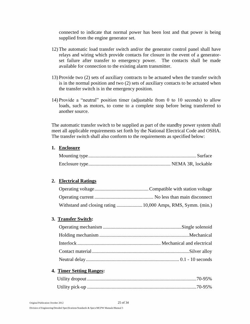
connected to indicate that normal power has been lost and that power is being
supplied from the engine generator set.
12) The automatic load transfer switch and/or the generator control panel shall have
relays and wiring which provide contacts for closure in the event of a generator-
set failure after transfer to emergency power. The contacts shall be made
available for connection to the existing alarm transmitter.
13) Provide two (2) sets of auxiliary contracts to be actuated when the transfer switch
is in the normal position and two (2) sets of auxiliary contacts to be actuated when
the transfer switch is in the emergency position.
14) Provide a “neutral” position timer (adjustable from 0 to 10 seconds) to allow
loads, such as motors, to come to a complete stop before being transferred to
another source.
The automatic transfer switch to be supplied as part of the standby power system shall
meet all applicable requirements set forth by the National Electrical Code and OSHA.
The transfer switch shall also conform to the requirements as specified below:
1. Enclosure
Mounting type ........................................................................................ Surface
Enclosure type ................................................................... NEMA 3R, lockable
2. Electrical Ratings
Operating voltage ............................................ Compatible with station voltage
Operating current ................................................ No less than main disconnect
Withstand and closing rating ..................... 10,000 Amps, RMS, Symm. (min.)
3. Transfer Switch:
Operating mechanism ................................................................ Single solenoid
Holding mechanism ......................................................................... Mechanical
Interlock .................................................................... Mechanical and electrical
Contact material ............................................................................... Silver alloy
Neutral delay ............................................................................ 0.1 - 10 seconds
4. Timer Setting Ranges:
Utility dropout ......................................................................................... 70-95%
Utility pick-up ......................................................................................... 70-95%
Page 26
Original Publication October 2012 26 of 34
Division of Engineering/Detailed Specifications/Standards & Specs/MCPW Manuals/Manual 5
Utility interrupt delay ......................................................................... 0.1-10 sec.
Engine min. run .................................................................................... 5-30 min.
Engine warm-up .................................................................................. 5-180 sec.
Return to utility delay ........................................................................... 1-30 min.
Engine cooldown .................................................................................. 1-30 min.
Standby voltage ....................................................................................... 70-90%
Standby frequency ................................................................................... 80-90%
Exerciser ............................................................................................ Once/week
5. Operation Selectors:
Exercise ................................................................................ With/Without load
Engine warm-up bypass .......................................................................... On/Off
Neutral delay ........................................................................................... On/Off
Mode selector ............................................................ Manual Test/Standby/Off
C. Standby Power System Capacity
The standby power system shall be capable of providing continuous standby power
for the wastewater pumping station. The generator set shall be capable of starting all
pump motor loads sequentially with the full miscellaneous load applied, with no more
than 30% dip. The minimum acceptable generator set rating shall be 25 KW for
any station. The CONTRACTOR/DEVELOPER shall coordinate the starting
requirements of the exact pumps being furnished on the project with the generator set
supplier to insure that the generator set has adequate motor starting capability.
D. Installation
The generator set shall be mounted and anchored to a reinforced concrete pad, one
foot above the 100 year flood, located to provide adequate access for fueling and
servicing. The exact dimensions of the pad, conduit entries and anchor bolts shall be
based on the manufacturer's shop drawings. The pad shall have outer dimensions 1
foot greater than the footprint of the base tank, to provide 6" of exposure on all sides.
All exposed edges shall be chamfered or rounded with an edging tool.
All connections to it shall be made with flexible pipe, conduit, etc., to minimize
transfer of vibration.
The automatic transfer switch shall be mounted beneath the rainshield as shown on
the DRAWINGS. All electrical work shall conform to the National Electrical Code.
Prior to shipment, the following tests shall be conducted at the plant of the
manufacturer, and certified results of these tests shall be delivered to the Engineer for
transmittal to the Owner:
Page 27
Original Publication October 2012 27 of 34
Division of Engineering/Detailed Specifications/Standards & Specs/MCPW Manuals/Manual 5
Full load test of the generator set for one hour with fuel consumption, output voltage,
engine speed, voltage and speed-regulation and generator winding temperature
measured and recorded at ten-minute intervals.
E. Tests
Authorized Distributor of the manufacturer shall inspect the equipment installation
after it is completed and perform initial start-up and test of the system and shall
submit a certificate of this inspection and test. The date of acceptance as referred to
hereinbefore is defined as the date on which this certificate of inspection and test is
received by the Owner. The following test shall be performed in the presence of the
Engineer or their representative:
(1) Generator output voltage unloaded and loaded, each phase, based on 2-hour
load bank test
(2) Voltage dip as loads are applied
(3) Complete operating sequence (simulated utility power failure and restoration)
(4) Pressure test engine cooling system for leaks
(5) Test battery charging systems
(6) Test operation of all safety systems
Upon completion of break-in and testing, the engine shall be serviced as follows:
Change engine oil and filter
Verify anti-freeze protection (-34° F)
Refill fuel tank (tank shall be left full)
Check belt tension
Check battery connections and state of charge
During this start-up period, the MCPW Utility maintenance personnel shall be fully
instructed in the proper maintenance of the standby power system.
F. Manufacturer
The generator set, controls, and transfer switch shall be furnished by a single supplier.
The generator set and accessory equipment shall be supplied by
Caterpillar/Olympian, Detroit Diesel/Spectrum or Kohler.
Page 28
Original Publication October 2012 28 of 34
Division of Engineering/Detailed Specifications/Standards & Specs/MCPW Manuals/Manual 5
The supplier shall be the authorized dealer of the engine-generator set manufacturer,
and shall be fully qualified and authorized to provide service and parts for the engine
and generator at any time during the day or night. Parts and service shall be available
24 hours per day 7 days a week, from a location within a 100-mile driving radius of
the location of the installed generator set.
G. Shop Drawings
Prior to purchase of stand-by power generation equipment, the Contractor shall
submit not less than four (4) sets of data to the Engineer for approval, including:
equipment data, accessories, sizing calculations, etc., as may be appropriate to
determine compliance with these Specifications.
H. Operating Instructions
Six (6) complete copies of operating instructions and parts list shall be provided prior
to acceptance of the unit. Parts list shall include schedule of type and quantity of
parts recommended for stock.
I. Spare Parts:
The following spare parts shall be furnished at the time of start-up to MCPW:
Engine Fan & Accessory Drive Belts .............................. 1 sets
Oil, Fuel & Air Filters ...................................................... 2 sets
Spare Indicator Lamps & Fuses ....................................... 2 sets
Other items as may be recommended by the manufacturer.
Spare parts shall be boxed and labeled with the pumping station identification.
J. Warranty
The complete standby power generating system shall be warranted for one year after
the acceptance of the generating system by the MCPW. The warranty shall cover all
defects in equipment, parts, assembly and installation. The warranty shall be issued
in writing by the supplier and delivered to the MCPW.
5.11 Pump Types
A. Provide standby auxiliary pumping system, including bypass pumps and the
auxiliary pumping system shall be activated by the Automic Trans for switch or
other approved means.
B. For Gorman Rupp pumping systems, an siti-start auxiliary pumping system is
acceptable.
Page 29
Original Publication October 2012 29 of 34
Division of Engineering/Detailed Specifications/Standards & Specs/MCPW Manuals/Manual 5
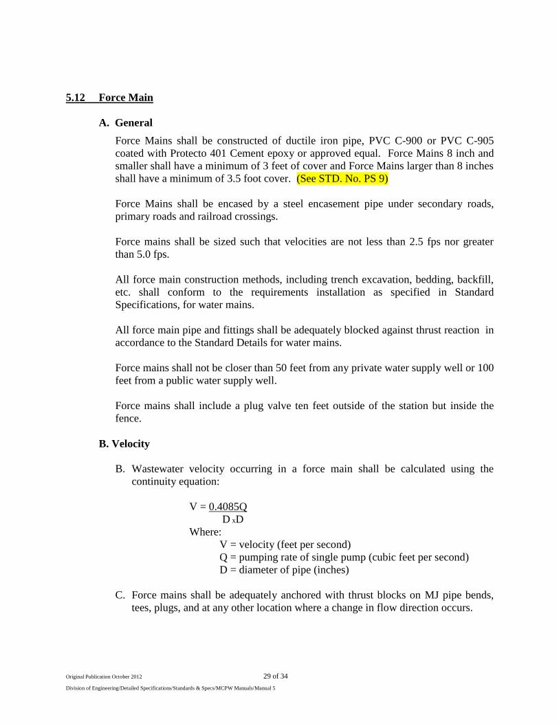
5.12 Force Main
A. General
Force Mains shall be constructed of ductile iron pipe, PVC C-900 or PVC C-905
coated with Protecto 401 Cement epoxy or approved equal. Force Mains 8 inch and
smaller shall have a minimum of 3 feet of cover and Force Mains larger than 8 inches
shall have a minimum of 3.5 foot cover. (See STD. No. PS 9)
Force Mains shall be encased by a steel encasement pipe under secondary roads,
primary roads and railroad crossings.
Force mains shall be sized such that velocities are not less than 2.5 fps nor greater
than 5.0 fps.
All force main construction methods, including trench excavation, bedding, backfill,
etc. shall conform to the requirements installation as specified in Standard
Specifications, for water mains.
All force main pipe and fittings shall be adequately blocked against thrust reaction in
accordance to the Standard Details for water mains.
Force mains shall not be closer than 50 feet from any private water supply well or 100
feet from a public water supply well.
Force mains shall include a plug valve ten feet outside of the station but inside the
fence.
B. Velocity
B. Wastewater velocity occurring in a force main shall be calculated using the
continuity equation:
V = 0.4085Q
D xD
Where:
V = velocity (feet per second)
Q = pumping rate of single pump (cubic feet per second)
D = diameter of pipe (inches)
C. Force mains shall be adequately anchored with thrust blocks on MJ pipe bends,
tees, plugs, and at any other location where a change in flow direction occurs.
Page 30
Original Publication October 2012 30 of 34
Division of Engineering/Detailed Specifications/Standards & Specs/MCPW Manuals/Manual 5
C. Ductile Iron Pipe
All ductile iron pipe shall be designed as per ANSI/AWWA C-151/A21.50.02 for a
minimum working pressure of 200 psi. Pipe wall thickness shall conform to
ANSI/AWWA C-150/A21.50-02. Pipe up to and including 12 inch diameter pipe
shall be Pressure Class 150 (min.), while pipe greater than 12 inch diameter shall be
Pressure Class 250. The County Engineer may require heavier class pipe on a case-
by case bases.
Pipe joints shall be of the push-on type with rubber gaskets as per ANSI/AWWA C-
111/A21.11-07. Mechanical or special joints may be used as project requirements
dictate or as required by the County Engineer. Pipe lining shall be Cement-Epoxy, on
the interior, while an external coat of bituminous material, all in accordance with
ANSI/AWWA C-104/A21.4-03. Where restrained joints are indicated Mega-Lugs or
Grip rings shall be used.
Ductile iron pipe shall be as manufactured by Griffin, U.S. Pipe, American, or Clow.
The pipe shall be furnished in 20-feet or 18 feet in lengths and be American made.
D. Polyvinyl Chloride Pipe, C-900 or C-909
PVC pipe shall be rigid polyvinyl chloride with integrally formed, factory fabricated
bell, with “slip” joint rubber gaskets conforming to ASSA C-111.. It shall be suitable
for all conditions imposed by plan locations and for a minimum working pressure of
200 psi, plus 100 psi surge allowance at 73 degree F. Pipe shall be Type 1, Grade 1,
made from clear virgin material and shall conform to the requirements of
ANSI/AWWA C-900-07. All pipe shall bear the National Sanitation Foundation Seal
of Approval, the manufacture’s name, and class of pipe. The joints shall conform to
ASTM D3139-98.
Provision must be made for expansion and contraction at each joint, through the
rubber gasket and pipe bell. Where restrained joints are indicated, Mega-Lugs or
Grip Rings shall be used.
E. HDPE, High Density Polyethylene Pipe
HDPE pipe for directional drilling must be DR-9, 250 psi, and sized to have the
inside diameter of the HDPE pipe to match the inside diameter of the connecting
Force Main. Connection of HDPE and Ductile Iron shall be level and made to
prevent binding of HDPE. All pipe shall be labeled ANSI/AWWA C906 and C901.
Pipe to conform to ASTM D2737.
HDPE after directional drilling should be allowed to contract (release) for 30 days
after which connection shall be made to three joints of DIP with Restricted
Page 31
Original Publication October 2012 31 of 34
Division of Engineering/Detailed Specifications/Standards & Specs/MCPW Manuals/Manual 5
Mechanical Joints, gate valves and reducers. A valve shall be placed between the first
and second joint of DIP at each end of the HDPE.
F. Fittings
Fittings for ductile iron pipe force mains, 4-inch diameter and larger, shall be ductile
or cast iron. Provide Stainless Steel bolts and nuts.
G. Air Release & Vacuum Relief Valves
1. Air release valves shall be located on lines where hydraulics indicates gas pockets
may accumulate.
2. The route of the force main shall be such that the number of air release and
vacuum relief valves are minimized to the greatest extent possible.
3. A Combination Valve will be needed where the distance between the low points
and high points in the Force Main exceeds 2 vertical feet. Each valve shall be
quick-opening, slow-closing type to prevent the development of hydraulic surge
conditions.
4. Use air release valves with flood protection in areas within the 100-year
floodplain or areas where flooding in anticipated to occur. Each valve shall be
equipped with flushing connections and one set of flushing hoses. Use CLA-
VAL Crispin or equal. (See STD. No. PS 8)
H. Gate Valves
12 inch and Smaller:
Gate valves 12 inch and smaller shall be of the resilient wedge type conforming to
ANSI/AWWA Standard C-509-01. They shall be designed for a working pressure of
200 psi. The valves shall be open-left (counter clockwise), non-rising stem, gray cast
iron or ductile iron body, with O-ring seals and a 2 inch square operating nut.
Extension stems shall be furnished when depth of bury places operating nut is in
excess of four feet below finished grade.
I. Plug Valves
Plug Valves shall be used in lieu of Gate Valves as they can be opened and closed
without concerns of creating a water hammer in sewer lines. Valves shall be full
body opening.
Plug Valves shall meet or exceed AWWA C-517. Valves can be side or top cranked
with heavy-duty fully rubber encapsulated plug, V-type packing that is self adjusting
and replaceable while under pressure. They shall be stainless steel radial for upper
and lower bearings that is permanently lubricated for extended life.
Page 32
Original Publication October 2012 32 of 34
Division of Engineering/Detailed Specifications/Standards & Specs/MCPW Manuals/Manual 5
J. Valve Markers
Valve Markers are to be installed in rural areas, near the right-of-way line, to better
identify their location for all other valve locations. In urban areas, valve markers are
to be installed only as recommended by the Engineer.
For Valve Marking and Valve Box Cover protection, provide a concrete protector
ring.
K. Stream Crossings
1. Force mains shall be routed such that the number of stream crossings is
minimized. The crossing shall be as nearly perpendicular to the stream flow as
possible. Ductile Iron pipe with joints equivalent to water main standards shall be
used to construct force mains that cross streams.
2. Ductile Iron pipe with flanged joints, with adequate supports, shall be used for
aerial stream crossing. Supports shall prevent frost heave, overturning, and
settlement, freezing, heaving, and the impact of floodwaters and debris shall be
considered during the design of aerial crossings. The bottom of the force main
pipes shall be placed no lower than 2 feet above the 100-year flood stage of the
stream unless approved by the Engineer.
L. Testing of Force Mains
All force mains shall be tested to water main standards. The section of force main to
be hydrostatically tested shall be slowly filled with water at a rate which will allow
complete evacuation of air from the line.
The line shall be tested to a pressure of 200 psi as measured at the lowest elevation of
the line for the duration of at least 24 hours. The pressure gauge used in the
hydrostatic test shall be calibrated in increments of 5 psi or less. At the end of the test
period, the leakage shall be measured with an accurate water meter.
No pressure pipe installation will be accepted until leakage is less than the number of
gallons per hour for each section tested, as determined by the following formula:
Q= LD
12,670
Q = Allowable leakage, in gallons per hour
L = Length of pipe tested, in feet
D = Number of joints in the length of line under test
Page 33
Original Publication October 2012 33 of 34
Division of Engineering/Detailed Specifications/Standards & Specs/MCPW Manuals/Manual 5
M. Utility Warning Tape
All force mains shall have Utility warning tape installed 18" below finish grade and
extended into valve boxes and manholes to facilitate location. The tape shall read
“Sewer Force Main Buried Below”.
N. Tracer Wire
Tracer wire shall be installed on all Force Mains. The wire shall be number 12 gauge
and colored Green.
All spliced or repaired wire connections in the tracer wire system shall be made using
a Wing Nut Wire Connector (for two to four number ten wires), or approved
equivalent, and made waterproof using an approved buried service wire closure. The
buried service wire closure shall be Frame Gel Closure or equivalent. Utility warning
tape shall be placed at a minimum of 18" beneath the ground surface and over the line
. (See Std. No. PS 9) The testing of tracer wire, after construction, shall be
performed by the contractor with the Engineer or their representative present.
O. Receiving Manholes
All receiving manholes shall be fully coated inside with an epoxy approved by the
County Engineer. Additional down stream manholes shall be fully coated as required
by the County Engineer. If the entrance pipe is 2 foot or greater higher than the outlet
pipe flow line a drop line shall be installed with a 45 degree bend aimed at the outlet
invert. (See STD. No. PS 10)
5.12 Quality Assurance and Quality Control
The following items are required to assure that the construction quality is acceptable and
that information has been provided to assure proper maintenance quality:
A. Six Operations and Maintenance (O&M) Manuals shall be prepared and provided
to MCPW before testing and start up for each pump station.
A copy of the O&M Manual shall be kept at MCPW office. The O&M Manual shall
be kept on file for the life of the pump station and updated as required.
B. Approved Shop Drawings, including design data for all installed equipment and each
major component and a pump curve/system curve analysis showing the design
operating point(s) and control panel wiring diagrams.
C. Complete Operating Instructions, including preventative and predictive
maintenance, for all installed equipment and each major component.
Instructions for start-up/shut-down as well as for calibration and adjustment of all
installed equipment and each major component.
Page 34
Original Publication October 2012 34 of 34
Division of Engineering/Detailed Specifications/Standards & Specs/MCPW Manuals/Manual 5
D. Warranty information for all installed equipment and each major component.
E. Construction Record Drawings that have been signed, sealed, and dated by a North
Carolina PE. Such drawings shall include, but shall not be limited to, the following:
1. Plan and profile views of the force main as installed as well as its proximity to
other utilities and natural resources. The locations of specific force main
materials as well as any valves and other force main appurtenances shall be
indicated.
2. Construction record detail drawings of the pump station.
5.13 Security
A. Access to Pump Station structures/equipment/appurtenances shall be restricted.
1. All entry into pump station shall be locked.
2. Fencing shall be six (6) feet in height and of sufficient material to deter entry.
Locked gates, a minimum of 12-feet wide, shall be provided to allow vehicular
access.
B. Safety Placards, as required by OSHA, shall be provided and be readily visible. (See
STD. No. PS 11)
C. A pump Station Identification Sign shall be posted, with the name, emergency
number, Station Address and instructions to call in the event of an alarm condition or
other emergency.
D. When non-submersible pumps are used above ground, a building Enclosure with
Gorman-Rupp Pumps shall be constructed to protect the pumps. If non-submersible
pumps are vaulted below ground or if submersible pumps are used no building shall
be constructed over the pumps.