WATCH: WiFi in Active TV Channels Xu Zhang and Edward W. Knightly Rice University, Houston, Texas, USA {Xu.Zhang,knightly}@rice.edu Abstract Today’s “white space” model of spectrum sharing applied in the UHF TV band allows channels that are not being used regionally by a TV broadcaster to be re-purposed for unlicensed-style secondary access in 24 hour increments. Un- fortunately, populated areas have few unused channels for white space usage. Nonetheless, from the UHF TV view- er’s perspective, Nielsen data show severe under-utilization of this spectrum, with vast regions that are in range of TV transmitters having no active TV receivers on multi- ple channels even at peak TV viewing times. In this paper, we present the design, implementation, and experimental e- valuation of WATCH (WiFi in Active TV CHannels), the first system to enable secondary WiFi transmission even in the presence of kilowatt-scale TV transmitters, while simul- taneously protecting TV receivers when they are active. To protect active TV receivers, WATCH includes a smartphone- based TV remote or an Internet-connected TV to inform the WATCH controller of TV receivers’ spatial-spectral re- quirements. To enable WiFi transmission in UHF bands, we design WATCH-IC (Interference Cancellation) and CAT (Constructive Addition Transmission) to (i) exploit the u- nique environment of asynchronous WiFi transmission in the presence of a strong streaming interferer, and (ii) require no coordination with legacy TV transmitters. With FCC per- mission to test our implementation, we show that WATCH can provide at least 6 times the total achievable rate to 4 watt secondary devices compared to current TV white space systems, while limiting the increase in TV channel switching time to less than 5%. Categories and Subject Descriptors C.2.1 [COMPUTER-COMMUNICATION NETWORK- S]: Network Architecture and Design—Wireless communication General Terms Design, Experimentation, Performance, Reliability Permission to make digital or hard copies of all or part of this work for personal or classroom use is granted without fee provided that copies are not made or distributed for profit or commercial advantage and that copies bear this notice and the full cita- tion on the first page. Copyrights for components of this work owned by others than ACM must be honored. Abstracting with credit is permitted. To copy otherwise, or re- publish, to post on servers or to redistribute to lists, requires prior specific permission and/or a fee. Request permissions from [email protected]. MobiHoc’15, June 22–25, 2015, Hangzhou, China. Copyright c 2015 ACM 978-1-4503-3489-1/15/06 ...$15.00. http://dx.doi.org/10.1145/2746285.2746313. Keywords Spectrum Re-use; TV White Space; Database Controller; TV Receiver Feedback; Interference Cancellation; Transmit Beamforming 1. INTRODUCTION The UHF band of 400 MHz to 700 MHz is often termed the “beach front property” of spectrum due to its superior range and penetration compared to higher frequency bands. Globally, this band is typically licensed to TV broadcast- ers, which can be considered as primary transmitters (or primary users, PU) because they have the highest priority to access the spectrum as protected incumbents. When a geographical region has no primary broadcaster on a par- ticular channel, that channel is said to be “TV white space (TVWS),” which is available for transmission by secondary users (SU) under today’s regulatory frameworks, e.g., in the U.S. [9] and U.K. [15]. Unfortunately, the large number of over-the-air TV broadcasters in many populated areas yields extremely limited white space availability [13]. Nonetheless, in practice, the number of viewers watching TV via UHF is dwarfed by those watching via satellite or cable. For exam- ple, in the U.S., only 7% to 10% of all TV households rely on over-the-air UHF broadcast for TV programming [5,20]. In this paper, we design, implement and evaluate WATCH, the first system that enables secondary WiFi transmission in active TV channels. WATCH exploits the property that few households are receiving UHF-band TV programming in a given channel, time, and location. Because TV transmitter- s cannot be rapidly power-cycled even if they temporarily have no receivers (due to high transmit power associated capacitance), nor can they direct their energy only towards active TV receivers, WATCH comprises the following three contributions. First, we propose a new spectrum sharing model and ob- tain an FCC license for its testing. 1 To date, TVWS models calculate exclusion zones (areas where secondary transmis- sions are not allowed/transmit power is set to zero) based on transmitting TV channels and their corresponding tower locations [9]. In contrast, we propose a dynamically com- puted exclusion zone characterized as the union of locations where secondary user transmit power must be reduced in order to protect active TV receivers. By exploiting that the receiver-based exclusion zone has a much smaller footprint 1 FCC experimental license call sign WH9XHJ and file num- ber 0121-EX-ST-2014.
Transcript
WATCH: WiFi in Active TV Channels
Xu Zhang and Edward W. KnightlyRice University, Houston, Texas, USA{Xu.Zhang,knightly}@rice.edu
AbstractToday’s “white space” model of spectrum sharing appliedin the UHF TV band allows channels that are not beingused regionally by a TV broadcaster to be re-purposed forunlicensed-style secondary access in 24 hour increments. Un-fortunately, populated areas have few unused channels forwhite space usage. Nonetheless, from the UHF TV view-er’s perspective, Nielsen data show severe under-utilizationof this spectrum, with vast regions that are in range ofTV transmitters having no active TV receivers on multi-ple channels even at peak TV viewing times. In this paper,we present the design, implementation, and experimental e-valuation of WATCH (WiFi in Active TV CHannels), thefirst system to enable secondary WiFi transmission even inthe presence of kilowatt-scale TV transmitters, while simul-taneously protecting TV receivers when they are active. Toprotect active TV receivers, WATCH includes a smartphone-based TV remote or an Internet-connected TV to informthe WATCH controller of TV receivers’ spatial-spectral re-quirements. To enable WiFi transmission in UHF bands,we design WATCH-IC (Interference Cancellation) and CAT(Constructive Addition Transmission) to (i) exploit the u-nique environment of asynchronous WiFi transmission in thepresence of a strong streaming interferer, and (ii) require nocoordination with legacy TV transmitters. With FCC per-mission to test our implementation, we show that WATCHcan provide at least 6 times the total achievable rate to 4watt secondary devices compared to current TV white spacesystems, while limiting the increase in TV channel switchingtime to less than 5%.
Categories and Subject DescriptorsC.2.1 [COMPUTER-COMMUNICATION NETWORK-
S]: Network Architecture and Design—Wireless communication
General TermsDesign, Experimentation, Performance, Reliability
KeywordsSpectrum Re-use; TV White Space; Database Controller;TV Receiver Feedback; Interference Cancellation; TransmitBeamforming
1. INTRODUCTIONThe UHF band of 400 MHz to 700 MHz is often termed
the “beach front property” of spectrum due to its superiorrange and penetration compared to higher frequency bands.Globally, this band is typically licensed to TV broadcast-ers, which can be considered as primary transmitters (orprimary users, PU) because they have the highest priorityto access the spectrum as protected incumbents. When ageographical region has no primary broadcaster on a par-ticular channel, that channel is said to be “TV white space(TVWS),” which is available for transmission by secondaryusers (SU) under today’s regulatory frameworks, e.g., in theU.S. [9] and U.K. [15]. Unfortunately, the large number ofover-the-air TV broadcasters in many populated areas yieldsextremely limited white space availability [13]. Nonetheless,in practice, the number of viewers watching TV via UHF isdwarfed by those watching via satellite or cable. For exam-ple, in the U.S., only 7% to 10% of all TV households relyon over-the-air UHF broadcast for TV programming [5,20].
In this paper, we design, implement and evaluate WATCH,the first system that enables secondary WiFi transmission inactive TV channels. WATCH exploits the property that fewhouseholds are receiving UHF-band TV programming in agiven channel, time, and location. Because TV transmitter-s cannot be rapidly power-cycled even if they temporarilyhave no receivers (due to high transmit power associatedcapacitance), nor can they direct their energy only towardsactive TV receivers, WATCH comprises the following threecontributions.
First, we propose a new spectrum sharing model and ob-tain an FCC license for its testing.1 To date, TVWS modelscalculate exclusion zones (areas where secondary transmis-sions are not allowed/transmit power is set to zero) basedon transmitting TV channels and their corresponding towerlocations [9]. In contrast, we propose a dynamically com-puted exclusion zone characterized as the union of locationswhere secondary user transmit power must be reduced inorder to protect active TV receivers. By exploiting that thereceiver-based exclusion zone has a much smaller footprint
1FCC experimental license call sign WH9XHJ and file num-ber 0121-EX-ST-2014.
TV service area
TV transmitter
SU-TXSU-RX
Exclusion zone
Inactive TV
Inactive TV
Active TV
(a)
TV service area
TV transmitter
SU-TXSU-RX
Exclusion zone
Inactive TV
Inactive TV
Active TV
(b)
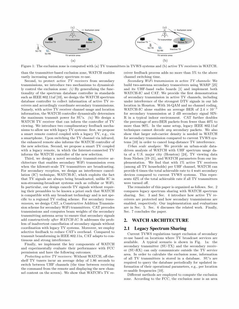
Figure 1: The exclusion zone is computed with (a) TV transmitters in TVWS systems and (b) active TV receivers in WATCH.
than the transmitter-based exclusion zone, WATCH enablesvastly increasing secondary spectrum re-use.
Second, to protect active TV receivers from secondarytransmissions, we introduce two mechanisms to dynamical-ly control the exclusion zone: (i) By generalizing the func-tionality of the spectrum database controller in standardssuch as IEEE 802.11af [10], we design the WATCH spectrumdatabase controller to collect information of active TV re-ceivers and accordingly coordinate secondary transmissions.Namely, with active TV receiver channel usage and locationinformation, the WATCH controller dynamically determinesthe maximum transmit power for SU’s. (ii) We design aWATCH TV receiver that can inform the controller of TVviewing. We introduce two complimentary feedback mecha-nisms to allow use with legacy TV systems: first, we proposea smart remote control coupled with a legacy TV, e.g., viaa smartphone. Upon switching the TV channel via infrared,the enhanced remote also informs the WATCH controller ofthe new selection. Second, we propose a smart TV coupledwith a legacy remote, in which the Internet-connected TVinforms the WATCH controller of the new selection.
Third, we design a novel secondary transmit-receive ar-chitecture that enables secondary WiFi transmission evenwhen the kilowatt-scale TV transmitters are broadcasting.For secondary reception, we design an interference cancel-lation (IC) technique, WATCH-IC, which exploits the factthat TV signals are always being broadcasted, unlike IC innon-streaming-broadcast systems such as cellular or WiFi.In particular, our design cancels TV signals without requir-ing their preambles to be known a priori such that WATCHis compatible with any broadcast technology and is not spe-cific to a regional TV coding scheme. For secondary trans-mission, we design CAT, a Constructive Addition Transmis-sion scheme for secondary WiFi transmitters. CAT precodestransmissions and computes beam weights of the secondarytransmitting antenna array to ensure that secondary signalsadd constructively after WATCH-IC. It addresses the prob-lem of inadvertent cancellation of secondary signals withoutcoordination with legacy TV systems. Moreover, we employselective feedback to reduce CAT’s overhead. Compared totransmit beamforming in IEEE 802.11n, CAT adapts to con-tinuous and strong interference.
Finally, we implement the key components of WATCHand experimentally evaluate their performance with FCCpermission and have the following outcomes.
Protecting active TV receivers: Without WATCH, off-the-shelf TV tuners incur an average delay of 1.86 seconds toswitch between UHF channels (the time between receivingthe command from the remote and displaying the new chan-nel content on the screen). We show that WATCH’s TV re-
ceiver feedback process adds no more than 5% to the abovechannel switching time.
Secondary WiFi transmission in active TV channels: Webuild two-antenna secondary transceivers using WARP [25]and its UHF-band radio boards [1] and implement bothWATCH-IC and CAT. We provide the first demonstrationof secondary transmission in active TV channels, includingunder interference of the strongest DTV signals in our lablocation in Houston. With 16-QAM and no channel coding,WATCH-IC alone enables an average BER of 2.4 × 10⁻³
for secondary transmission at 2 dB secondary signal SIN-R in a typical indoor environment. CAT further doublesthe percentage of zero-BER packets from fewer than 40% tomore than 90%. In the same setup, legacy IEEE 802.11aftechniques cannot decode any secondary packets. We alsoshow that larger sub-carrier density is needed in WATCHfor secondary transmission compared to current TVWS sys-tems [10] in order to cancel long-distance TV interference.
Urban scale analysis: We provide an urban-scale data-driven analysis of WATCH with UHF spectrum usage da-ta of a U.S. major city (Houston) [24], TV viewing datafrom Nielsen [19–21], and WATCH parameters from our im-plementation. We find that with 1% active TV receivers(among all TV households) per UHF channel, WATCH canprovide 6 times the total achievable rate to 4 watt secondarydevices compared to current TVWS systems. This repre-sents 42% of the total achievable rate if all TV transmitterswere turned off.
The remainder of this paper is organized as follows. Sec. 2compares legacy spectrum sharing with WATCH spectrumsharing. Sec. 3 and Sec. 4 introduce how active TV re-ceivers are protected and how secondary transmissions areenabled, respectively. Our implementation and evaluationsare in Sec. 5. Sec. 6 discusses the related work. Finally,Sec. 7 concludes the paper.
2. WATCH ARCHITECTURE
2.1 Legacy Spectrum SharingCurrent TVWS regulations target exclusion of secondary
re-use based on locations where TV broadcast services areavailable. A typical scenario is shown in Fig. 1a: thesecondary transmitter (SU-TX) and the secondary receiv-er (SU-RX) can only communicate outside the TV servicearea. In order to calculate the exclusion zone, informationof all TV transmitters is stored in a database. SU’s arerequired to query the database periodically for updated in-formation of their operational parameters, e.g., per locationre-usable frequencies [10].
Different methods are employed to compute the exclusionzone. According to the FCC, the exclusion zone is an area
where the TV signal strength exceeds a pre-defined value,which is calculated by the TV service threshold, SU antennaheight, etc. Outside this area, fixed secondary devices areallowed to transmit at up to 4 W EIRP (Effective IsotropicRadiation Power/transmit power including antenna gains),while personal/portable secondary devices are restricted to100 mW EIRP, or 40 mW EIRP if there are TV transmittersoccupying at least one of the two adjacent UHF channel-s [9]. In comparison, Ofcom divides space into 100 m×100m blocks with each one having a calculated maximum SUEIRP [15].
region determined by TV transmitter. However, becausethe percentage of active TV receivers relying on over-the-airUHF broadcasts is very small [5,20], we can re-purpose spec-trum even within the TV service area: (i) Spectrum in thespatial gaps: In-between active TV receivers, we allow sec-ondary transmissions without interfering with TV receivers.(ii) Spectrum in the temporal gaps: When a TV receiver isnot tuned into a particular TV channel, we allow secondarytransmissions in that channel and in the region around theTV receiver.
While current TVWS systems cannot re-use both of theabove spectrum opportunities, WATCH enables re-use bydynamically deciding the per-channel exclusion zone basedon protection of only active TV receivers. As illustratedin Fig. 1b, the TV transmitter location is now irrelevantto WATCH, because only active TV receivers can triggersecondary exclusion. The exclusion zone for each channel isalso dynamic and adapted each time a TV receiver is tunedin or out of that channel.
SUSignal
Primary Feedback
Spectrum Database Controller
TV Signal
WATCH-IC
CAT
Primary TV Transmitter
Primary TV Receiver
Secondary Transmitter
Secondary Receiver
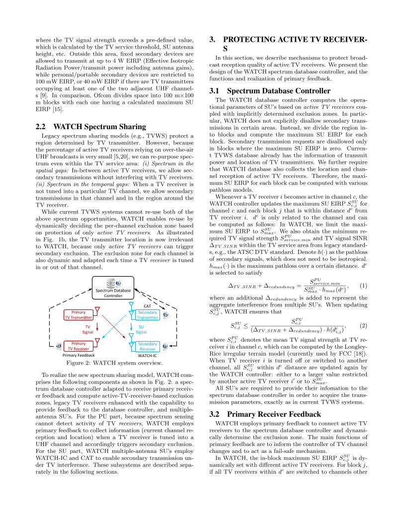
Figure 2: WATCH system overview.
To realize the new spectrum sharing model, WATCH com-prises the following components as shown in Fig. 2: a spec-trum database controller adapted to receive primary receiv-er feedback and compute active-TV-receiver-based exclusionzones, legacy TV receivers enhanced with the capability toprovide feedback to the database controller, and multiple-antenna SU’s. For the PU part, because spectrum sensingcannot detect activity of TV receivers, WATCH employsprimary feedback to collect information (current channel re-ception and location) when a TV receiver is tuned into aUHF channel and accordingly triggers secondary exclusion.For the SU part, WATCH multiple-antenna SU’s employWATCH-IC and CAT to enable secondary transmission un-der TV interference. These subsystems are described sepa-rately in the following sections.
3. PROTECTING ACTIVE TV RECEIVER-S
In this section, we describe mechanisms to protect broad-cast reception quality of active TV receivers. We present thedesign of the WATCH spectrum database controller, and thefunctions and realization of primary feedback.
3.1 Spectrum Database ControllerThe WATCH database controller computes the opera-
tional parameters of SU’s based on active TV receivers cou-pled with implicitly determined exclusion zones. In partic-ular, WATCH does not explicitly disallow secondary trans-missions in certain areas. Instead, we divide the region in-to blocks and compute the maximum SU EIRP for eachblock. Secondary transmission requests are disallowed onlyin blocks where the maximum SU EIRP is zero. Curren-t TVWS database already has the information of transmitpower and location of TV transmitters. We further requirethat WATCH database also collects the location and chan-nel reception of active TV receivers. Therefore, the maxi-mum SU EIRP for each block can be computed with variouspathloss models.
Whenever a TV receiver i becomes active in channel c, theWATCH controller updates the maximum SU EIRP SSUc,j forchannel c and each block j that is within distance dc fromTV receiver i. dc is only related to the channel and canbe computed as follows: In WATCH, we limit the maxi-mum SU EIRP to SSUmax. We also obtain the minimum re-quired TV signal strength SPUservice min and TV signal SINR∆TV SINR within the TV service area from legacy standard-s, e.g., the ATSC DTV standard. Denote h(·) as the pathlossof secondary signals, which does not need to be isotropical.hmax(·) is the maximum pathloss over a certain distance. dc
is selected to satisfy
∆TV SINR + ∆redundency =SPUservice min
SSUmax · hmax(dc), (1)
where an additional ∆redundency is added to represent theaggregate interference from multiple SU’s. When updatingSSUc,j , WATCH ensures that
SSUc,j ≤SPUc,i
(∆TV SINR + ∆redundency) · h(dci,j), (2)
where SPUc,i denotes the mean TV signal strength at TV re-ceiver i in channel c, which can be computed by the Longley-Rice irregular terrain model (currently used by FCC [18]).When TV receiver i is turned off or switched to anotherchannel, all SSUc,j within dc distance are updated again bythe WATCH controller: either to a larger value restrictedby another active TV receiver i′ or to SSUmax.
All SU’s are required to provide their infomation to thespectrum database controller in order to acquire the trans-mission parameters, exactly as in current TVWS systems.
3.2 Primary Receiver FeedbackWATCH employs primary feedback to connect active TV
receivers to the spectrum database controller and dynami-cally determine the exclusion zone. The main functions ofprimary feedback are to inform the controller of TV channelchanges and to act as a fail-safe mechanism.
In WATCH, the in-block maximum SU EIRP SSUc,j is dy-namically set with different active TV receivers. For block j,if all TV receivers within dc are switched to channels other
than c or turned off, SSUc,j is reset to SSUmax (for either a TVreceiver i or a block j, calculations are limited to SU’s orPU’s within distance dc). However, channel changes of TVreceivers cannot be detected by external techniques such asspectrum sensing. Therefore, we require active TV receiver-s to inform the database controller of the channel changesthrough primary feedback.
After a TV receiver informs the controller that it is tunedinto a particular UHF channel c, the controller updates al-l SSUc,j within dc. However, if the active TV receiver isnonetheless incurring excessive interference due to the errorsin either the collected data, (errors in locations of PU’s/SU’s,errors in pathloss estimates, etc.), WATCH employs the fol-lowing fail-safe mechanism: If a TV receiver infers that thereis excessive interference, the WATCH controller will gradu-ally increase ∆redundency, grow the exclusion zone, and re-calculate SSUc,j , until that the TV receiver can successfullydecode the TV programming. If ∆redundency exceeds a pre-defined threshold ∆max
redundancy and the TV receiver still infersbeing interfered, WATCH controller will consider that theexcessive interference is due to poor channel quality of TVsignals instead of SU interference.
3.3 Primary Feedback SubsystemWhile the broadcasting TV signals and the secondary data
are sent in the UHF band, primary feedback can be trans-mitted out-of-band via WiFi, cellular, or wired connectionssuch as DSL, or in-band via a UHF feedback channel. Wepropose two methods to implement primary feedback withminimum modifications to legacy TV systems: (i) Smartremote: Smartphones can control TVs via infrared, e.g.,Samsung Galaxy S5 and HTC One M8.2 Consequently, s-martphones can be used as combined feedback and remotedevices. (ii) Smart TV: Feedback can be sent via the TV’sInternet access.
The required feedback in the previous discussion consid-ers all channels (TV channels, UHF channels) as identical.However, in practice, channels are divided into two types: aphysical channel which occupies 6 MHz bandwidth and a vir-tual channel which contains TV programming. Each phys-ical channel can comprise several virtual channels. There-fore, when an active TV receiver is switched between virtualchannels but stays in the same physical channel, it does notneed to contact the controller. Feedback is required onlywhen the TV receiver is switched between physical channel-s. According to [8], TV viewers switch among virtual chan-nels with an average of 2.3-2.7 times per hour. The rateof physical channel switch cannot be larger, which indicatesthat the primary feedback of channel switch will not be sentvery frequently. For the fail-safe mechanism, the value of∆redundency determines how well active TV receivers can beprotected. A large initial ∆redundency reduces the amount offeedback to trigger the fail-safe mechanism, whereas in themeantime increases the possibility to excessively limit theSU EIRP.
In order to analyze the quality degradation of broadcastvideo reception that occurs immediately following a phys-ical channel switch, we denote tlegacy as the time that alegacy TV receiver takes to switch between physical chan-nels, which includes physical signal decode, transport streamdemultiplexing and video data decode. WATCH increasestlegacy to tWATCH by adding an additional delay used by the
2http://en.wikipedia.org/wiki/Infrared_blaster
SU-RX
SU-TX
PU-TXHPU1
HPU2
HSU1
HSU2
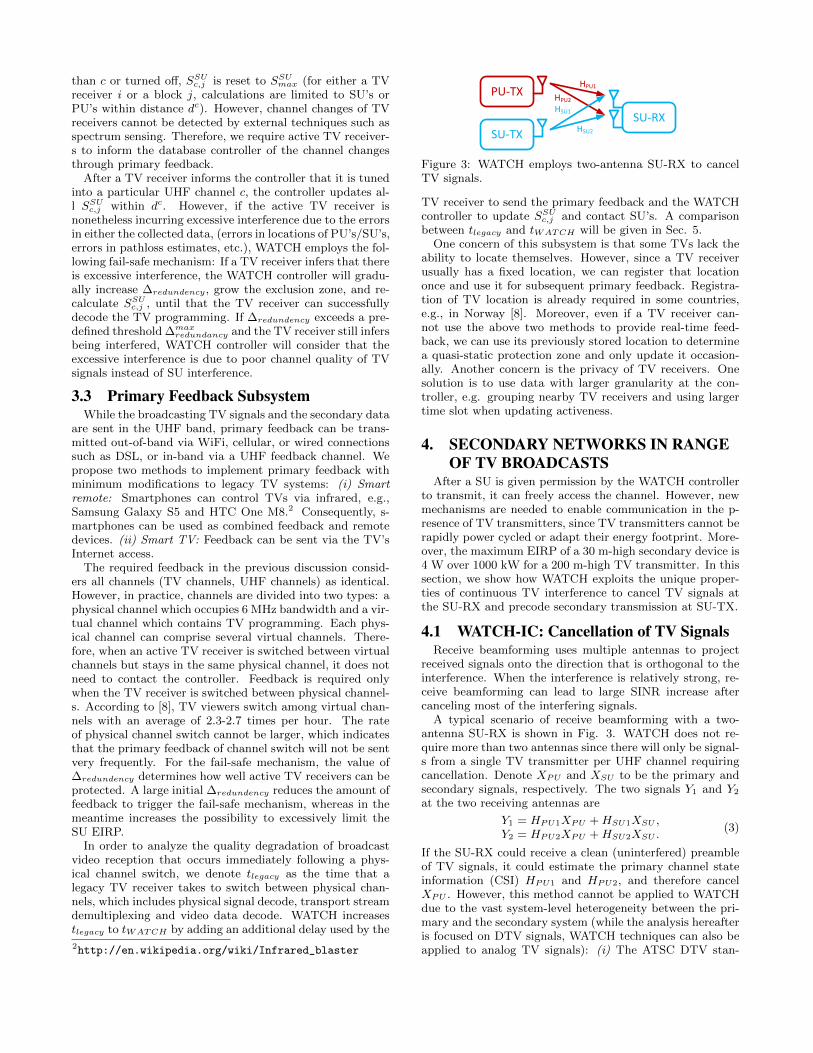
Figure 3: WATCH employs two-antenna SU-RX to cancelTV signals.
TV receiver to send the primary feedback and the WATCHcontroller to update SSUc,j and contact SU’s. A comparisonbetween tlegacy and tWATCH will be given in Sec. 5.
One concern of this subsystem is that some TVs lack theability to locate themselves. However, since a TV receiverusually has a fixed location, we can register that locationonce and use it for subsequent primary feedback. Registra-tion of TV location is already required in some countries,e.g., in Norway [8]. Moreover, even if a TV receiver can-not use the above two methods to provide real-time feed-back, we can use its previously stored location to determinea quasi-static protection zone and only update it occasion-ally. Another concern is the privacy of TV receivers. Onesolution is to use data with larger granularity at the con-troller, e.g. grouping nearby TV receivers and using largertime slot when updating activeness.
4. SECONDARY NETWORKS IN RANGEOF TV BROADCASTS
After a SU is given permission by the WATCH controllerto transmit, it can freely access the channel. However, newmechanisms are needed to enable communication in the p-resence of TV transmitters, since TV transmitters cannot berapidly power cycled or adapt their energy footprint. More-over, the maximum EIRP of a 30 m-high secondary device is4 W over 1000 kW for a 200 m-high TV transmitter. In thissection, we show how WATCH exploits the unique proper-ties of continuous TV interference to cancel TV signals atthe SU-RX and precode secondary transmission at SU-TX.
4.1 WATCH-IC: Cancellation of TV SignalsReceive beamforming uses multiple antennas to project
received signals onto the direction that is orthogonal to theinterference. When the interference is relatively strong, re-ceive beamforming can lead to large SINR increase aftercanceling most of the interfering signals.
A typical scenario of receive beamforming with a two-antenna SU-RX is shown in Fig. 3. WATCH does not re-quire more than two antennas since there will only be signal-s from a single TV transmitter per UHF channel requiringcancellation. Denote XPU and XSU to be the primary andsecondary signals, respectively. The two signals Y1 and Y2
at the two receiving antennas are
Y1 = HPU1XPU +HSU1XSU ,Y2 = HPU2XPU +HSU2XSU .
(3)
If the SU-RX could receive a clean (uninterfered) preambleof TV signals, it could estimate the primary channel stateinformation (CSI) HPU1 and HPU2, and therefore cancelXPU . However, this method cannot be applied to WATCHdue to the vast system-level heterogeneity between the pri-mary and the secondary system (while the analysis hereafteris focused on DTV signals, WATCH techniques can also beapplied to analog TV signals): (i) The ATSC DTV stan-
SU-RX
SU-TX
PU-TXHPU1
HPU2HSU11
HSU21
HSU22HSU12α
β
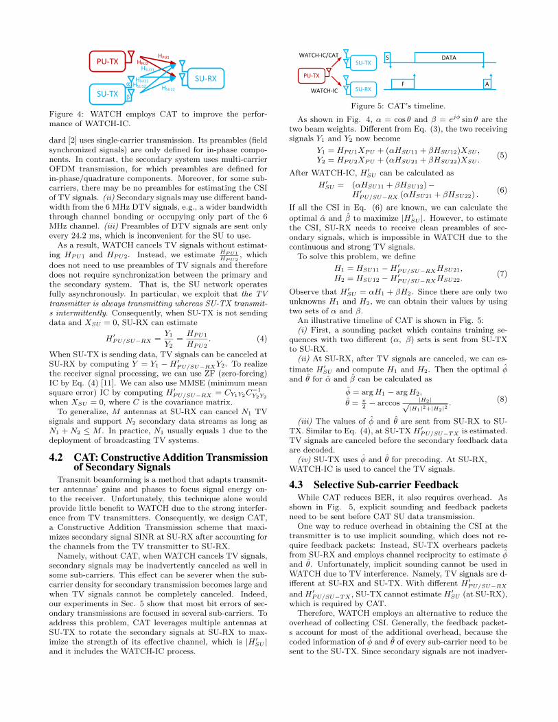
Figure 4: WATCH employs CAT to improve the perfor-mance of WATCH-IC.
dard [2] uses single-carrier transmission. Its preambles (fieldsynchronized signals) are only defined for in-phase compo-nents. In contrast, the secondary system uses multi-carrierOFDM transmission, for which preambles are defined forin-phase/quadrature components. Moreover, for some sub-carriers, there may be no preambles for estimating the CSIof TV signals. (ii) Secondary signals may use different band-width from the 6 MHz DTV signals, e.g., a wider bandwidththrough channel bonding or occupying only part of the 6MHz channel. (iii) Preambles of DTV signals are sent onlyevery 24.2 ms, which is inconvenient for the SU to use.
As a result, WATCH cancels TV signals without estimat-ing HPU1 and HPU2. Instead, we estimate HPU1
HPU2, which
does not need to use preambles of TV signals and thereforedoes not require synchronization between the primary andthe secondary system. That is, the SU network operatesfully asynchronously. In particular, we exploit that the TVtransmitter is always transmitting whereas SU-TX transmit-s intermittently. Consequently, when SU-TX is not sendingdata and XSU = 0, SU-RX can estimate
H ′PU/SU−RX =Y1
Y2=HPU1
HPU2. (4)
When SU-TX is sending data, TV signals can be canceled atSU-RX by computing Y = Y1 −H ′PU/SU−RXY2. To realizethe receiver signal processing, we can use ZF (zero-forcing)IC by Eq. (4) [11]. We can also use MMSE (minimum meansquare error) IC by computing H ′PU/SU−RX = CY1Y2C
−1Y2Y2
when XSU = 0, where C is the covariance matrix.To generalize, M antennas at SU-RX can cancel N1 TV
signals and support N2 secondary data streams as long asN1 + N2 ≤ M . In practice, N1 usually equals 1 due to thedeployment of broadcasting TV systems.
Transmit beamforming is a method that adapts transmit-ter antennas’ gains and phases to focus signal energy on-to the receiver. Unfortunately, this technique alone wouldprovide little benefit to WATCH due to the strong interfer-ence from TV transmitters. Consequently, we design CAT,a Constructive Addition Transmission scheme that maxi-mizes secondary signal SINR at SU-RX after accounting forthe channels from the TV transmitter to SU-RX.
Namely, without CAT, when WATCH cancels TV signals,secondary signals may be inadvertently canceled as well insome sub-carriers. This effect can be severer when the sub-carrier density for secondary transmission becomes large andwhen TV signals cannot be completely canceled. Indeed,our experiments in Sec. 5 show that most bit errors of sec-ondary transmissions are focused in several sub-carriers. Toaddress this problem, CAT leverages multiple antennas atSU-TX to rotate the secondary signals at SU-RX to max-imize the strength of its effective channel, which is |H ′SU |and it includes the WATCH-IC process.
PU-TX
F
DATAWATCH-IC/CAT
WATCH-IC
SU-TX
SU-RXA
S
Figure 5: CAT’s timeline.
As shown in Fig. 4, α = cos θ and β = ejφ sin θ are thetwo beam weights. Different from Eq. (3), the two receivingsignals Y1 and Y2 now become
If all the CSI in Eq. (6) are known, we can calculate the
optimal α and β to maximize |H ′SU |. However, to estimatethe CSI, SU-RX needs to receive clean preambles of sec-ondary signals, which is impossible in WATCH due to thecontinuous and strong TV signals.
Observe that H ′SU = αH1 + βH2. Since there are only twounknowns H1 and H2, we can obtain their values by usingtwo sets of α and β.
An illustrative timeline of CAT is shown in Fig. 5:(i) First, a sounding packet which contains training se-
quences with two different (α, β) sets is sent from SU-TXto SU-RX.
(ii) At SU-RX, after TV signals are canceled, we can es-
timate H ′SU and compute H1 and H2. Then the optimal φand θ for α and β can be calculated as
φ = argH1 − argH2,
θ = π2− arccos |H2|√
|H1|2+|H2|2. (8)
(iii) The values of φ and θ are sent from SU-RX to SU-TX. Similar to Eq. (4), at SU-TX H ′PU/SU−TX is estimated.TV signals are canceled before the secondary feedback dataare decoded.
(iv) SU-TX uses φ and θ for precoding. At SU-RX,WATCH-IC is used to cancel the TV signals.
4.3 Selective Sub-carrier FeedbackWhile CAT reduces BER, it also requires overhead. As
shown in Fig. 5, explicit sounding and feedback packetsneed to be sent before CAT SU data transmission.
One way to reduce overhead in obtaining the CSI at thetransmitter is to use implicit sounding, which does not re-quire feedback packets: Instead, SU-TX overhears packetsfrom SU-RX and employs channel reciprocity to estimate φand θ. Unfortunately, implicit sounding cannot be used inWATCH due to TV interference. Namely, TV signals are d-ifferent at SU-RX and SU-TX. With different H ′PU/SU−RXand H ′PU/SU−TX , SU-TX cannot estimate H ′SU (at SU-RX),which is required by CAT.
Therefore, WATCH employs an alternative to reduce theoverhead of collecting CSI. Generally, the feedback packet-s account for most of the additional overhead, because thecoded information of φ and θ of every sub-carrier need to besent to the SU-TX. Since secondary signals are not inadver-
Combine
TV Signals
WARP SU-TXLegacy TV
Transmitter
Off-the-shelfTV Tuners
Primary Feedback
(a) PU sub-system
SUData
TV Signals WARP SU-TX
WARP SU-RX
Legacy TV Transmitter
(b) SU sub-system
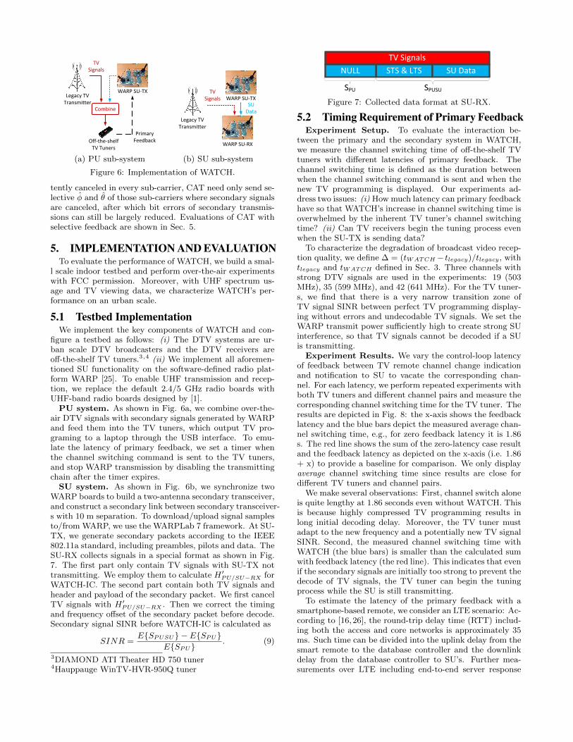
Figure 6: Implementation of WATCH.
tently canceled in every sub-carrier, CAT need only send se-lective φ and θ of those sub-carriers where secondary signalsare canceled, after which bit errors of secondary transmis-sions can still be largely reduced. Evaluations of CAT withselective feedback are shown in Sec. 5.
5. IMPLEMENTATION AND EVALUATIONTo evaluate the performance of WATCH, we build a smal-
l scale indoor testbed and perform over-the-air experimentswith FCC permission. Moreover, with UHF spectrum us-age and TV viewing data, we characterize WATCH’s per-formance on an urban scale.
5.1 Testbed ImplementationWe implement the key components of WATCH and con-
figure a testbed as follows: (i) The DTV systems are ur-ban scale DTV broadcasters and the DTV receivers areoff-the-shelf TV tuners.3,4 (ii) We implement all aforemen-tioned SU functionality on the software-defined radio plat-form WARP [25]. To enable UHF transmission and recep-tion, we replace the default 2.4/5 GHz radio boards withUHF-band radio boards designed by [1].
PU system. As shown in Fig. 6a, we combine over-the-air DTV signals with secondary signals generated by WARPand feed them into the TV tuners, which output TV pro-graming to a laptop through the USB interface. To emu-late the latency of primary feedback, we set a timer whenthe channel switching command is sent to the TV tuners,and stop WARP transmission by disabling the transmittingchain after the timer expires.
SU system. As shown in Fig. 6b, we synchronize twoWARP boards to build a two-antenna secondary transceiver,and construct a secondary link between secondary transceiver-s with 10 m separation. To download/upload signal samplesto/from WARP, we use the WARPLab 7 framework. At SU-TX, we generate secondary packets according to the IEEE802.11a standard, including preambles, pilots and data. TheSU-RX collects signals in a special format as shown in Fig.7. The first part only contain TV signals with SU-TX nottransmitting. We employ them to calculate H ′PU/SU−RX forWATCH-IC. The second part contain both TV signals andheader and payload of the secondary packet. We first cancelTV signals with H ′PU/SU−RX . Then we correct the timingand frequency offset of the secondary packet before decode.Secondary signal SINR before WATCH-IC is calculated as
SINR =E{SPUSU} − E{SPU}
E{SPU}. (9)
3DIAMOND ATI Theater HD 750 tuner4Hauppauge WinTV-HVR-950Q tuner
TV Signals
STS & LTS SU DataNULL
SPU SPUSU
Figure 7: Collected data format at SU-RX.
5.2 Timing Requirement of Primary FeedbackExperiment Setup. To evaluate the interaction be-
tween the primary and the secondary system in WATCH,we measure the channel switching time of off-the-shelf TVtuners with different latencies of primary feedback. Thechannel switching time is defined as the duration betweenwhen the channel switching command is sent and when thenew TV programming is displayed. Our experiments ad-dress two issues: (i) How much latency can primary feedbackhave so that WATCH’s increase in channel switching time isoverwhelmed by the inherent TV tuner’s channel switchingtime? (ii) Can TV receivers begin the tuning process evenwhen the SU-TX is sending data?
To characterize the degradation of broadcast video recep-tion quality, we define ∆ = (tWATCH− tlegacy)/tlegacy, withtlegacy and tWATCH defined in Sec. 3. Three channels withstrong DTV signals are used in the experiments: 19 (503MHz), 35 (599 MHz), and 42 (641 MHz). For the TV tuner-s, we find that there is a very narrow transition zone ofTV signal SINR between perfect TV programming display-ing without errors and undecodable TV signals. We set theWARP transmit power sufficiently high to create strong SUinterference, so that TV signals cannot be decoded if a SUis transmitting.
Experiment Results. We vary the control-loop latencyof feedback between TV remote channel change indicationand notification to SU to vacate the corresponding chan-nel. For each latency, we perform repeated experiments withboth TV tuners and different channel pairs and measure thecorresponding channel switching time for the TV tuner. Theresults are depicted in Fig. 8: the x-axis shows the feedbacklatency and the blue bars depict the measured average chan-nel switching time, e.g., for zero feedback latency it is 1.86s. The red line shows the sum of the zero-latency case resultand the feedback latency as depicted on the x-axis (i.e. 1.86+ x) to provide a baseline for comparison. We only displayaverage channel switching time since results are close fordifferent TV tuners and channel pairs.
We make several observations: First, channel switch aloneis quite lengthy at 1.86 seconds even without WATCH. Thisis because highly compressed TV programming results inlong initial decoding delay. Moreover, the TV tuner mustadapt to the new frequency and a potentially new TV signalSINR. Second, the measured channel switching time withWATCH (the blue bars) is smaller than the calculated sumwith feedback latency (the red line). This indicates that evenif the secondary signals are initially too strong to prevent thedecode of TV signals, the TV tuner can begin the tuningprocess while the SU is still transmitting.
To estimate the latency of the primary feedback with asmartphone-based remote, we consider an LTE scenario: Ac-cording to [16,26], the round-trip delay time (RTT) includ-ing both the access and core networks is approximately 35ms. Such time can be divided into the uplink delay from thesmart remote to the database controller and the downlinkdelay from the database controller to SU’s. Further mea-surements over LTE including end-to-end server response
0 100 200 300 400 500 600 7000
0.5
1.0
1.5
2.0
2.5
3.0
3.5
Latency of the primary feedback process (ms)Channel switching time (s)
Figure 8: Measured channel switching time with differentprimary feedback latencies.
delay to a large database server report about 80 ms averageRTT.5 Finding: In a full-scale system, the expected primaryfeedback latency of WATCH will be less than 100 ms, whichleads to an additional channel switching time of TV’s with∆ < 5%. Use of a wire-connected Smart TV can furtherreduce ∆ due to smaller RTT.
5.3 Cancellation of TV SignalsTo evaluate WATCH under the most adversarial condi-
tions, we sweep all UHF channels and select the one withthe strongest DTV signal, which is channel 26 (545 MHz) inour lab location at Rice University. According to [24], theTV transmitter of channel 26 is approximately 17 km awayfrom our lab and it can broadcast at a maximum of 1300kW EIRP. In TVWS systems, this channel is clearly exclud-ed from secondary transmission. Consequently, we receivedan experimental license from the FCC to conduct the firstexperiments of secondary transmission in active TV chan-nels. Since channel 26 contains the strongest DTV signals,our analysis shows the lower-bound performance of WATCHin our lab. For evaluation, we separately evaluate WATCH-IC and CAT, with this sub-section considering WATCH-ICwithout CAT.
Experiment Setup. Because the primary (single-carrier)and the secondary (multi-carrier) system use different mod-ulation, it is important to determine the sub-carrier den-sity (number of sub-carriers in certain bandwidth) for sec-ondary transmission required by WATCH in diverse prima-ry/secondary environments. SU transmissions in our ex-periments use 5 MHz bandwidth, 16-QAM and no channelcoding. For different secondary signal SINR, we vary thetransmit power at SU-TX. We also change the sub-carrierdensity of SU transmission from 64 to 512. The samplingrate and buffer size of WARP limit that we can use at most512 sub-carriers for 5 MHz bandwidth.
Experiment Results. The results are shown in Fig. 9.The x-axis is the maximum SINR of secondary signals atthe two receiving antennas before WATCH-IC (we do notuse average SINR since BER is more related to one of thetwo receiving signals that has larger SINR). The y-axis isthe average BER of secondary signals. There are five curvesin the figure: The upper dashed curve shows the BER beforeWATCH-IC, whereas the bottom four solid curves show theBER after WATCH-IC.
Without WATCH-IC, the BER is near 0.5 (random guess-ing) indicating a complete failure if legacy systems are used.
Without IC With IC, 64 sub−carriers With IC, 128 sub−carriers With IC, 256 sub−carriers With IC, 512 sub−carriers
Figure 9: Impact of sub-carrier density on MMSE WATCH-IC.
However, after WATCH cancels the TV signals, the BER de-creases, with larger sub-carrier density having a more rapiddecreasing rate (indicating better cancellation). At 2 dBsecondary signal SINR, the BER for 64 and 512 sub-carriersis 1.9 × 10⁻² and 2.4 × 10⁻³ respectively. In the experi-ments, while the increase of secondary signal strength afterWATCH-IC is similar, the cancellation degree of TV signalsvary significantly with different sub-carrier densities.
Generally, the required sub-carrier density is governedby the delay spread (coherence bandwidth) of the signal-s, so that channel fading can be considered flat over anOFDM sub-carrier. However, in WATCH, the required sub-carrier density of secondary signals is dominated by the de-lay spread of TV signals. In our experiments, the distancefrom the SU-TX to the SU-RX is only 10 m, whereas the dis-tance from the TV transmitter to the SU-RX is 17 km. Ac-cording to [17], the delay spread of the UHF band for indoorWLANs is smaller than 1 µs, while that for tower-to-homeenvironments with tens of kilometers of distance is 11 to 25µs. Therefore, even for short range secondary transmission,in order to sufficiently cancel TV signals, a large sub-carrierdensity is required. This sharply contrasts with the TVWSstandard: In IEEE 802.11af, SU’s only use 144 sub-carriersfor 6 MHz bandwidth (equivalent to 120 sub-carriers for 5MHz bandwidth) [10]. Finding: To sufficiently cancel TVsignals with large delay spread, WATCH requires high sub-carrier density even for short range secondary transmission.
We analyze the impact of other operational parameters ofthe secondary system in [32] due to space limitations.
In the following, we evaluate the performance of CAT cou-pled with WATCH-IC.
Experiment Setup. For repeatable experiments, we col-lect over-the-air channel traces and evaluate CAT with TVsignals received in channel 26. We use channel 29 (563 MHz)to collect the CSI between SU-TX and SU-RX. According toGoogle Spectrum Database, there are no co-channel TV sig-nals in channel 29 in our lab, so that we can collect thesecondary CSI without TV interference. For trace post-processing, 5 MHz secondary signals are generated with 512sub-carriers, 16-QAM and no channel coding. The signalsare transmitted through secondary channels first and thenmixed with TV signals.
Out of the 512 sub-carriers, only 396 are used to trans-mit data/pilots (non-silent sub-carriers). To evaluate se-
lective feedback, we only send φ and θ of N% of the 396non-silent sub-carriers to the SU-TX. As shown in Sec. 4.2,
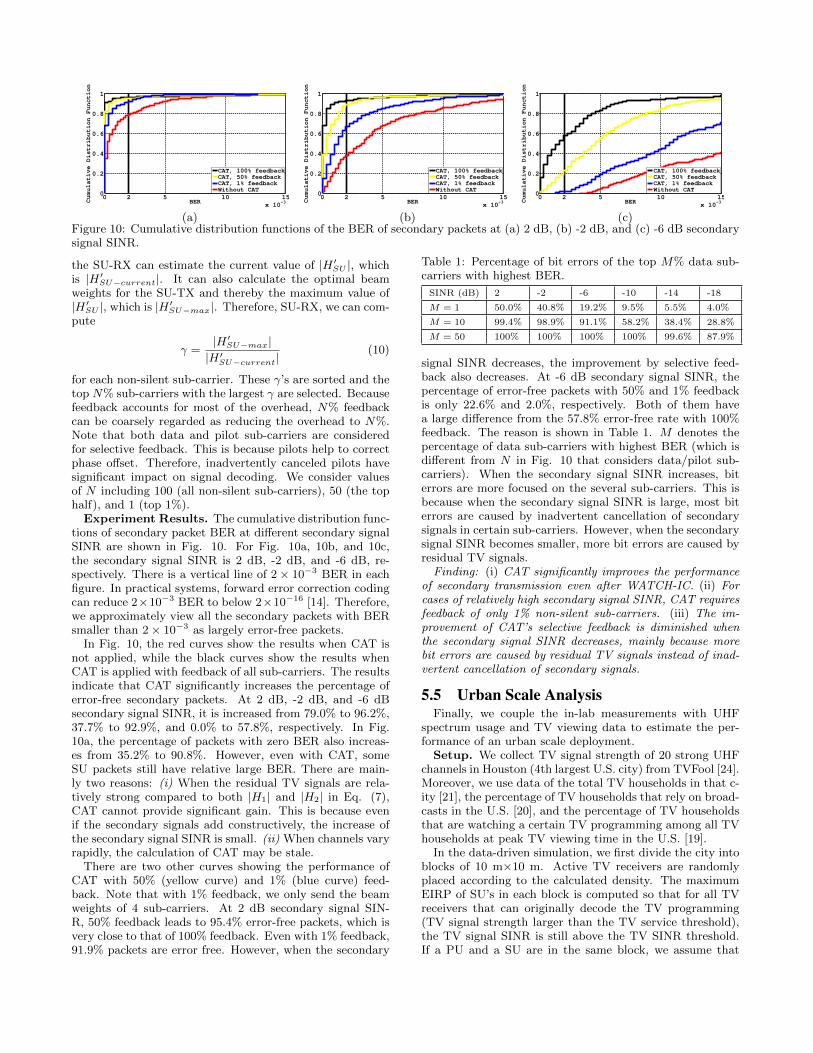
(c)Figure 10: Cumulative distribution functions of the BER of secondary packets at (a) 2 dB, (b) -2 dB, and (c) -6 dB secondarysignal SINR.
the SU-RX can estimate the current value of |H ′SU |, whichis |H ′SU−current|. It can also calculate the optimal beamweights for the SU-TX and thereby the maximum value of|H ′SU |, which is |H ′SU−max|. Therefore, SU-RX, we can com-pute
γ =|H ′SU−max||H ′SU−current|
(10)
for each non-silent sub-carrier. These γ’s are sorted and thetop N% sub-carriers with the largest γ are selected. Becausefeedback accounts for most of the overhead, N% feedbackcan be coarsely regarded as reducing the overhead to N%.Note that both data and pilot sub-carriers are consideredfor selective feedback. This is because pilots help to correctphase offset. Therefore, inadvertently canceled pilots havesignificant impact on signal decoding. We consider valuesof N including 100 (all non-silent sub-carriers), 50 (the tophalf), and 1 (top 1%).
Experiment Results. The cumulative distribution func-tions of secondary packet BER at different secondary signalSINR are shown in Fig. 10. For Fig. 10a, 10b, and 10c,the secondary signal SINR is 2 dB, -2 dB, and -6 dB, re-spectively. There is a vertical line of 2× 10⁻³ BER in eachfigure. In practical systems, forward error correction codingcan reduce 2×10⁻³ BER to below 2×10⁻¹⁶ [14]. Therefore,we approximately view all the secondary packets with BERsmaller than 2× 10⁻³ as largely error-free packets.
In Fig. 10, the red curves show the results when CAT isnot applied, while the black curves show the results whenCAT is applied with feedback of all sub-carriers. The resultsindicate that CAT significantly increases the percentage oferror-free secondary packets. At 2 dB, -2 dB, and -6 dBsecondary signal SINR, it is increased from 79.0% to 96.2%,37.7% to 92.9%, and 0.0% to 57.8%, respectively. In Fig.10a, the percentage of packets with zero BER also increas-es from 35.2% to 90.8%. However, even with CAT, someSU packets still have relative large BER. There are main-ly two reasons: (i) When the residual TV signals are rela-tively strong compared to both |H1| and |H2| in Eq. (7),CAT cannot provide significant gain. This is because evenif the secondary signals add constructively, the increase ofthe secondary signal SINR is small. (ii) When channels varyrapidly, the calculation of CAT may be stale.
There are two other curves showing the performance ofCAT with 50% (yellow curve) and 1% (blue curve) feed-back. Note that with 1% feedback, we only send the beamweights of 4 sub-carriers. At 2 dB secondary signal SIN-R, 50% feedback leads to 95.4% error-free packets, which isvery close to that of 100% feedback. Even with 1% feedback,91.9% packets are error free. However, when the secondary
Table 1: Percentage of bit errors of the top M% data sub-carriers with highest BER.
SINR (dB) 2 -2 -6 -10 -14 -18
M = 1 50.0% 40.8% 19.2% 9.5% 5.5% 4.0%
M = 10 99.4% 98.9% 91.1% 58.2% 38.4% 28.8%
M = 50 100% 100% 100% 100% 99.6% 87.9%
signal SINR decreases, the improvement by selective feed-back also decreases. At -6 dB secondary signal SINR, thepercentage of error-free packets with 50% and 1% feedbackis only 22.6% and 2.0%, respectively. Both of them havea large difference from the 57.8% error-free rate with 100%feedback. The reason is shown in Table 1. M denotes thepercentage of data sub-carriers with highest BER (which isdifferent from N in Fig. 10 that considers data/pilot sub-carriers). When the secondary signal SINR increases, biterrors are more focused on the several sub-carriers. This isbecause when the secondary signal SINR is large, most biterrors are caused by inadvertent cancellation of secondarysignals in certain sub-carriers. However, when the secondarysignal SINR becomes smaller, more bit errors are caused byresidual TV signals.
Finding: (i) CAT significantly improves the performanceof secondary transmission even after WATCH-IC. (ii) Forcases of relatively high secondary signal SINR, CAT requiresfeedback of only 1% non-silent sub-carriers. (iii) The im-provement of CAT’s selective feedback is diminished whenthe secondary signal SINR decreases, mainly because morebit errors are caused by residual TV signals instead of inad-vertent cancellation of secondary signals.
5.5 Urban Scale AnalysisFinally, we couple the in-lab measurements with UHF
spectrum usage and TV viewing data to estimate the per-formance of an urban scale deployment.
Setup. We collect TV signal strength of 20 strong UHFchannels in Houston (4th largest U.S. city) from TVFool [24].Moreover, we use data of the total TV households in that c-ity [21], the percentage of TV households that rely on broad-casts in the U.S. [20], and the percentage of TV householdsthat are watching a certain TV programming among all TVhouseholds at peak TV viewing time in the U.S. [19].
In the data-driven simulation, we first divide the city intoblocks of 10 m×10 m. Active TV receivers are randomlyplaced according to the calculated density. The maximumEIRP of SU’s in each block is computed so that for all TVreceivers that can originally decode the TV programming(TV signal strength larger than the TV service threshold),the TV signal SINR is still above the TV SINR threshold.If a PU and a SU are in the same block, we assume that
Table 2: Parameters for urban scale analysis.
MAX SU EIRP [9] – SSUmax 4 W
SU-TX, SU-RX/PU-RX Antenna Height 3/10 m
TV SINR Threshold 23+10 dB
– ∆TV SINR [9]+∆redundency
TV Service Threshold [9] – SPUservice min -84 dBm/6 MHz
Noise Floor [9, 31] -114 dBm/6 MHz
SU-SU/SU-PU Reference Distance 10/5 m
there is a SU-PU reference distance between them. We alsoassume that SU-TX and SU-RX are separated by a SU-SUreference distance. For the secondary signal pathloss, weemploy the Extended-Hata and Hata-SRD model [7]. Eventhough here the coverage of each SU-TX is a sphere, in prac-tice WATCH can be used with any non-isotropical pathlossmodels. The achievable rates of secondary links in all theblocks are calculated with Shannon equation, which are thenaveraged over the whole urban area yielding spatial-spectralefficiency results with unit bits/sec/Hz/m2. Table 2 sum-marizes the parameters.
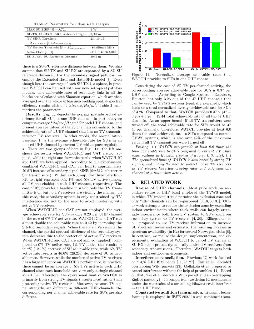
Results. Fig. 11 depicts the average spatial-spectral ef-ficiency for all SU’s in one UHF channel. In particular, wecompute average bits/sec/Hz/m2 for each UHF channel andpresent average values of the 20 channels normalized to theachievable rate of a UHF channel that has no TV transmit-ters nor TV receivers. In other words, the normalizationbaseline, 1, is the average achievable rate for SU’s in anunused UHF channel by current TV white space regulation-s. There are two groups of bars in Fig. 11: the left oneshows the results when WATCH-IC and CAT are not ap-plied, while the right one shows the results when WATCH-ICand CAT are both applied. According to our experiments,combined WATCH-IC and CAT can lead to approximately20 dB increase of secondary signal SINR (for 512-sub-carrierSU transmission). Within each group, the three bars fromleft to right represent 0%, 1%, and 5% TV active (amongall TV households) in each UHF channel, respectively. Thecase of 0% provides a baseline in which only the TV trans-mitter is on but no TV receivers are viewing the channel. Inthis case, the secondary system is only constrained by TVinterference and not by the need to avoid interfering withactive TV receivers.
When WATCH-IC and CAT are not employed, the aver-age achievable rate for SU’s is only 0.23 per UHF channelin the case of 0% TV active rate. WATCH-IC and CAT canalmost double the achievable rate to 0.42 by increasing theSINR of secondary signals. When there are TVs viewing thechannel, the spatial-spectral efficiency of the secondary sys-tem decreases due to the protection of active TV receivers.When WATCH-IC and CAT are not applied (applied), com-pared to 0% TV active rate, 1% TV active rate results in22.2% (12.7%) decrease of SU achievable rate, while 5% TVactive rate results in 46.6% (28.2%) decrease of SU achiev-able rate. However, while the number of active TV receivershas a large influence on WATCH’s performance, in practice,there cannot be an average of 5% TVs active in each UHFchannel since each household can view only a single channelat a time. Therefore, the operational limit of WATCH isprimarily from strong TV signals (interference) rather thanprotecting active TV receivers. Moreover, because TV sig-nal strengths are different in different UHF channels, thecorresponding per channel achievable rate for SU’s are alsodifferent.
Without WATCH−IC/CAT With WATCH−IC/CAT0
0.1
0.2
0.3
0.4
0.5
Normalized average
achievable rate in a channel
0% TV active per UHF channel
1% TV active per UHF channel
5% TV active per UHF channel
Figure 11: Normalized average achievable rates thatWATCH provides to SU’s in one UHF channel
Considering the case of 1% TV per-channel activity, thecorresponding average achievable rate for SU’s is 0.37 perUHF channel. According to Google Spectrum Database,Houston has only 3.26 out of the 47 UHF channels thatcan be used by TVWS systems (spatially averaged), whichleads to a total normalized average achievable rate for SU’sof 3.26. Compared to that, WATCH provides 0.37 × (47 −3.26) + 3.26 = 19.44 total achievable rate of all the 47 UHFchannels. As an upper bound, if all TV transmitters wereturned off, the total achievable rate for SU’s would be 47(1 per channel). Therefore, WATCH provides at least 6.0times the total achievable rate to SU’s compared to currentTVWS systems, which is also over 42% of the maximumvalue if all TV transmitters were turned off.
Finding: (i) WATCH can provide at least 6.0 times thetotal achievable rate to SU’s compared to current TV whitespace systems in Houston (typical of a large U.S. city). (ii)The operational limit of WATCH is dominated by strong TVsignals, and not by the need to protect active TV receiversas TV viewers have low viewing rates and only view onechannel at a time when active.
6. RELATED WORKRe-use of UHF channels. Most prior work on sec-
ondary re-use of UHF band employed the TVWS model,in which TV transmitters determine the exclusion zone andonly “idle” channels can be re-purposed [3, 18, 30, 31]. Oth-er work attempts to reduce the exclusion zone by excludingindoor environments where thick walls can largely atten-uate interference both from TV system to SU’s and fromsecondary system to TV receivers [4, 28]. Ellingsaeter etal. proposed to use TV receiver information to increaseSU spectrum re-use and estimated the resulting increase inspectrum availability (in Hz) for several Norwegian cities [8].In contrast, we realize the design, implementation, and ex-perimental evaluation of WATCH to cancel TV signals atSU-RX’s and protect dynamically active TV receivers fromsecondary transmissions. Therefore, WATCH targets bothindoor and outdoor environments.
Interference cancellation. Previous IC work focusedon 2.4/5 GHz ISM bands [11, 23, 27]. Tan et al. decodedoverlapping WiFi packets [23]. Gollakota et al. proposed tocancel interference without the help of preambles [11]. Basedon that, Yan et al. decode a WiFi packet and an overlappingZigBee packet [27]. In comparison, we design IC mechanismsunder the constraint of a streaming kilowatt-scale interfererin the UHF band.
Constructive addition transmission. Transmit beam-forming is employed in IEEE 802.11n and combined trans-
mit beamforming (interference alignment) and receive beam-forming (interference cancellation) have been proposed forWiFi bands [6, 12, 29]. However, such techniques requirecoordination among different access points/clients. In con-trast, TV transmitters are non-adaptive to the secondarysystem in our scenario. CAT also operates under continu-ous and strong interfering TV signals.
Noam et al. proposed to send secondary signals in thenull-space of the interference channel of primary signals atthe primary receiver, so that interference to the primary re-ceiver is minimized [22]. However, this technique requiresmultiple-antenna PU and SU, with the primary transmitteradaptively beamforming to the primary receiver accordingto interference and channel conditions. In comparison, CATis compatible with legacy single-antenna broadcast TV sys-tems. The purpose of CAT is also different, which is to avoidinadvertent cancellation of secondary signals.
7. CONCLUSIONIn this paper, we propose WATCH, the first system to en-
able secondary WiFi transmission during active TV broad-casts. WATCH utilizes primary receiver feedback to protectincumbent TV reception. We also design WATCH-IC andCAT to enable secondary WiFi transmission under inter-ference from streaming kilowatt-scale TV transmitters. Webuild a testbed and evaluate WATCH with FCC permissionand show that in a typical U.S. major city, WATCH canprovide at least 6 times the total achievable rate to SU’scompared to current TVWS regulatory models, while at thesame time only increasing TV channel switching time by lessthan 5%.
8. ACKNOWLEDGMENTSThe authors would like to thank Narendra Anand and
Ryan Guerra for their assistance in performing the experi-ments. This research was supported by Cisco Systems, In-tel, the Keck Foundation, and by NSF grants CNS-1444056,CNS-1126478 and CNS-1012831.
9. REFERENCES[1] N. Anand, R. Guerra, and E. Knightly. The Case for
UHF-Band MU-MIMO. In Proc. of ACM MobiCom, 2014.[2] ATSC. ATSC Digital Television Standard – Part 2:
RF/Transmission System Characteristics, 2011.
[3] P. Bahl, R. Chandra, T. Moscibroda, R. Murty, andM. Welsh. White Space Networking with Wi-Fi LikeConnectivity. In Proc. of ACM SIGCOMM, 2009.
[4] L. Bedogni, A. Achtzehn, M. Petrova, and P. Mahonen.Smart Meters with TV Gray Spaces Connectivity: AFeasibility Study for Two Reference Network Topologies. InProc. of IEEE SECON, 2014.
[5] CEA. U.S. Household Television Usage Update. http://store.ce.org/Default.aspx?TabID=251&productId=328850,2013.
[6] L. Ching-Ju, S. Gollakota, and D. Katabi. Random AccessHeterogeneous MIMO Networks. In Proc. of ACMSIGCOMM, 2011.
[7] CPTE. Extended Hata and Hata-SRD Models.http://tractool.seamcat.org/wiki/Manual/PropagationModels/ExtendedHata.
[8] B. Ellingsaeter, H. Bezabih, J. Noll, and T. Maseng. UsingTV Receiver Information to Increase Cognitive WhiteSpace Spectrum. In Proc. of IEEE DYSPAN, 2012.
[9] FCC. Second Report and Order and Memorandum Opinionand Order in the Matter of Unlicensed Operation in the
TV Broadcast Bands Additional Spectrum for UnlicensedDevices below 900 MHz and in the 3 GHz Band, 2008.
[10] A. Flores, R. Guerra, E. Knightly, P. Ecclesine, andS. Pandey. IEEE 802.11af: A Standard for TV White SpaceSpectrum Sharing. IEEE Communications Magazine,51(10):92–100, 2013.
[11] S. Gollakota, F. Adib, D. Katabi, and S. Seshan. Clearingthe RF Smog: Making 802.11n Robust to Cross-TechnologyInterference. In Proc. of ACM SIGCOMM, 2011.
[12] S. Gollakota, S. Perli, and D. Katabi. InterferenceAlignment and Cancellation. In Proc. of ACM SIGCOMM,2009.
[13] K. Harrison, S. Mishra, and A. Sahai. How MuchWhite-Space Capacity Is There? In Proc. of IEEEDYSPAN, 2010.
[14] ITU. ITU-T Recommendation G.975.1.http://www.itu.int/rec/T-REC-G.975.1, 2004.
[15] H. Karimi. A Framework for Calculation of TV WhiteSpace Availability Subject to the Protection of DTT andPMSE. In Proc. of IEEE PIMRC, 2013.
[16] M. Laner, P. Svoboda, P. Romirer-Maierhofer, N. Nikaein,F. Ricciato, and M. Rupp. A Comparison betweenOne-Way Delays in Operating HSPA and LTE Networks. InProc. of IEEE WiOpt, 2012.
[17] D. Lekomtcev and R. Marsalek. Comparison of 802.11 afand 802.22 Standards – Physical Layer and CognitiveFunctionality. Elektro Revue, 3(2):12–18, 2012.
[18] R. Murty, R. Chandra, T. Moscibroda, and P. Bahl.Senseless: A Database-Driven White Spaces Network. InProc. of IEEE DYSPAN, 2011.
[19] Nielsen. Nielsen Top 10 List. http://www.nielsen.com/content/corporate/us/en/top10s.html.
[21] Nielsen. Local Television Market Universe Estimates.http://www.nielsen.com/content/dam/corporate/us/en/docs/solutions/measurement/television/2013-2014-DMA-Ranks.pdf, 2014.
[22] Y. Noam and A. Goldsmith. Blind Null-Space Learning forMIMO Underlay Cognitive Radio with Primary UserInterference Adaptation. IEEE Transactions on WirelessCommunications, 12(4):1722–1734, 2013.
[23] K. Tan, H. Liu, J. Fang, W. Wang, J. Zhang, M. Chen, andG. Voelker. SAM: Enabling Practical Spatial MultipleAccess in Wireless LAN. In Proc. of ACM MobiCom, 2009.
[24] TVFOOL. http://www.tvfool.com/.
[25] WARP. http://mangocomm.com/.
[26] M. Wylie-Green and T. Svensson. Throughput, Capacity,Handover and Latency Performance in a 3GPP LTE FDDField Trial. In Proc. of IEEE GLOBECOM, 2010.
[27] Y. Yan, P. Yang, X. Li, Y. Tao, L. Zhang, and L. You.ZIMO: Building Cross-technology MIMO to HarmonizeZigBee Smog with WiFi Flash Without Intervention. InProc. of ACM MobiCom, 2013.
[28] X. Ying, J. Zhang, L. Yan, G. Zhang, M. Chen, andR. Chandra. Exploring Indoor White Spaces inMetropolises. In Proc. of ACM MobiCom, 2013.
[29] H. Yu, O. Bejarano, and L. Zhong. Combating Inter-cellInterference in 802.11ac-based Multi-user MIMO Networks.In Proc. of ACM MobiCom, 2014.
[30] Y. Yuan, P. Bahl, R. Chandra, P. A. Chou, I. Ferrell,T. Moscibroda, S. Narlanka, and Y. Wu. KNOWS:Kognitiv Networking Over White Spaces. In Proc. of IEEEDYSPAN, 2007.
[31] T. Zhang, N. Leng, and S. Banerjee. A Vehicle-basedMeasurement Framework for Enhancing WhitespaceSpectrum Databases. In Proc. of ACM MobiCom, 2014.
[32] X. Zhang. WATCH: WiFi in Active TV Channels (MasterThesis), Rice University, Houston, Texas.