112
Armidale Regional Landfill Armidale Dumaresq Council Water and Leachate Management Plan Armidale Regional Landfill

Armidale Regional Landfill Armidale Dumaresq Council
Water and Leachate Management Plan
Armidale Regional Landfill

AECOM Water and Leachate Management Plan – Armidale Regional Landfill
26-Feb-2016 Prepared for – Armidale Dumaresq Council – ABN: 63 781 014 253
Water and Leachate Management Plan Armidale Regional Landfill
Client: Armidale Dumaresq Council
ABN: 63 781 014 253
Prepared by
Level 21, 420 George Street, Sydney NSW 2000, PO Box Q410, QVB Post Office NSW 1230, Australia T +61 2 8934 0000 F +61 2 8934 0001 www.aecom.com
26-Feb-2016
Job No.: ARLF-LEMP-RP-0009-WLMP-C
AECOM in Australia and New Zealand is certified to the latest version of ISO9001, ISO14001, AS/NZS4801 and OHSAS18001.
© AECOM Australia Pty Ltd (AECOM). All rights reserved.
AECOM has prepared this document for the sole use of the Client and for a specific purpose, each as expressly stated in the document. No other party should rely on this document without the prior written consent of AECOM. AECOM undertakes no duty, nor accepts any responsibility, to any third party who may rely upon or use this document. This document has been prepared based on the Client’s description of its requirements and AECOM’s experience, having regard to assumptions that AECOM can reasonably be expected to make in accordance with sound professional principles. AECOM may also have relied upon information provided by the Client and other third parties to prepare this document, some of which may not have been verified. Subject to the above conditions, this document may be transmitted, reproduced or disseminated only in its entirety.

AECOM Water and Leachate Management Plan – Armidale Regional Landfill
26-Feb-2016 Prepared for – Armidale Dumaresq Council – ABN: 63 781 014 253
Quality Information
Document Water and Leachate Management Plan
Ref ARLF-LEMP-RP-0009-WLMP-C
Date 26-Feb-2016
Prepared by Roweena McKenzie/Luke Chipperfield and Alexandra Frolich
Reviewed by Danielle Poirier and Andrew Kielniacz
Revision History
Revision Revision Date Details
Authorised
Name/Position Signature
Revision 1 21/4/2008 Draft for Review Jamon Pool Project Manager On original
Final 17/2/2010 Final Draft Danielle Phillips Project Manager On original
A 5-May-2015 Revised Draft for Council review
Danielle Phillips Associate Director - Environment
A 25/05/2015 Revised Mike Brooks Armidale Dumaresq Council
B 21/10/2015 Final draft for issue to EPA and DPI Water
Duncan Price Project Manager
C 26/02/2016 Issue to DP&E for approval Danielle Poirier Associate Director - Environment
AECOM Water and Leachate Management Plan – Armidale Regional Landfill
26-Feb-2016 Prepared for – Armidale Dumaresq Council – ABN: 63 781 014 253
Contents 1.0 Introduction 1
1.1 Project Background 1 1.1.1 Consultation 1
1.2 Purpose and Scope 1 1.3 Objectives 1 1.4 Structure of this Plan 2
2.0 Statutory Requirements 4 2.1 Approval Requirements 4 2.2 Licenses and Permits 6 2.3 Relevant Legislation and Guidelines 6
2.3.1 Water Licensing 6 3.0 Existing Site Characteristics 8
3.1 Existing Environment 8 3.1.1 Catchment 8 3.1.2 Flooding 8
3.2 Sensitive Receivers 8 3.3 Potential Impacts 11
4.0 Water Management Strategy 13 4.1 EPA Requirements 13 4.2 Classification of Site Water 13 4.3 Water Management 13
4.3.1 Clean Water Management 15 4.3.2 Dirty Water Management 15 4.3.3 Leachate Water 15
5.0 Roles and Responsibilities 16 6.0 Water and Leachate Management 17
6.1 Applicable Design Guidelines 17 6.2 Cell 1 Landfill 17 6.3 Leachate Barrier System 18 6.4 Leachate Collection and Conveyance System 19 6.5 Leachate Storage Pond 20 6.6 Sedimentation Basin 21 6.7 Dry Basin 22 6.8 Surface Water Drainage 23
6.8.1 Clean Water Diversion Drains 23 6.8.2 Dirty Water Drains 25 6.8.3 Road Culvert Crossings 25 6.8.4 Clean Water Drain Outlets 26
6.9 Leachate Return System 26 6.10 Erosion and Sediment Control Measures 27
7.0 Water and Leachate Monitoring 28 7.1 Surface and Groundwater Monitoring 28 7.2 Onsite Leachate Monitoring 28
8.0 Contamination Remediation 29 8.1 Emergency Conditions and Response Actions 29
8.1.1 Leachate Storage Pond Freeboard Capacity Exceeded 29 8.1.2 Contamination of the Dry Basin Water 29 8.1.3 Remediation of the Sedimentation and Dry Basins 29 8.1.4 Downstream Surface Water Contamination 30
8.2 Remediation of Surface and Groundwater Contamination 31 9.0 Review and Continual Improvement 32
9.1 Records 32 9.2 Reporting 32 9.3 Review 32
10.0 References 33

AECOM Water and Leachate Management Plan – Armidale Regional Landfill
26-Feb-2016 Prepared for – Armidale Dumaresq Council – ABN: 63 781 014 253
List of Tables Body Report
Table 1 Management Plan Requirements 4 Table 2 Summary of Responsibilities 16 Table 3 Design guideline documents 17 Table 4 Clay Fill Material Compliance Criteria 19 Table 5 Minimum Sedimentation Basin Capacity 21 Table 6 Clean Water Diversion Drain - Hydraulic Capacity Results for 100yr Peak Flows 24 Table 7 Clean Water Diversion Drain - Hydraulic Channel Lining Results for 20yr Peak Flows 25 Table 8 Culvert Hydraulic Analysis Results 26
List of Figures Body Report
Figure 1 Environmental Management Structure 2 Figure 2 Project site location 9 Figure 3 Sensitive Receivers 10 Figure 4 Armidale Regional Landfill Conceptual Site Model 12 Figure 5 Site Water Management Strategy 14
List of Appendices Appendix A Design Report
Appendix B Water Management Design Drawings
Appendix C Water Quality Monitoring Plan

AECOM Water and Leachate Management Plan – Armidale Regional Landfill
26-Feb-2016 Prepared for – Armidale Dumaresq Council – ABN: 63 781 014 253
i
Abbreviations CEMP Construction Environmental Management Plan
DP&E Department of Planning and Environment
DPI Department of Primary Industries
EPA Environment Protection Authority
EPL Environment Protection Licence
ESCP Erosion and Sediment Control Plan
GRAWHA Gondwana Rainforests of Australia World Heritage Area
HDPE High-density polyethylene
LEMP Landfill Environmental Management Plan
NOW NSW Office of Water
OEH Office of Environment and Heritage
OWRNP Oxley Wild Rivers National Park
PAHs Polycyclic Aromatic Hydrocarbons
POEO Act Protection of the Environment Operations Act 1997
STP Sewage Treatment Plant
TPH Total Petroleum Hydrocarbons
TSR Travelling Stock Route
WLMP Water and Leachate Management Plan
WQMP Water Quality Monitoring and Management Plan
WSP Water Sharing Plan

AECOM Water and Leachate Management Plan – Armidale Regional Landfill
26-Feb-2016 Prepared for – Armidale Dumaresq Council – ABN: 63 781 014 253
1
1.0 Introduction
1.1 Project Background Armidale Dumaresq Council (Council) has approval for the construction and operation of a new regional landfill facility to service the Armidale region. The landfill facility is located on Waterfall Way, approximately 12 km east of Armidale.
The Planning Assessment Commission, as delegate for the NSW Minister for Planning and Infrastructure, granted approval for the project under Section 75J of the Environmental Planning and Assessment Act 1979, subject to conditions, on 4 July 2012. The project involves construction and operation of a landfill comprising five cells, each cell with a maximum volume of 211,000m3.
AECOM has been engaged by Council to prepare this Water and Leachate Management Plan to manage the operation of the new landfill facility. It has been developed to ensure that both surface water and leachate is successfully controlled and managed during the operational life of the landfill.
1.1.1 Consultation
A copy of this Plan was provided to the NSW Environment Protection Authority (EPA) and NSW Department of Primary Industries (DPI) Water (formerly NSW Office of Water) on 23 October 2015 in accordance with consultation requirements under Condition 9 of Schedule 4 of the Project Approval. Additional information (second round of groundwater monitoring results) was also provided to DPI Water on 2 November 2015.
Comments were received from DPI Water on 23 November providing feedback and recommendations for the plan. AECOM, on behalf of Council, responded to the comments raised by DPI Water who responded in further correspondence dated 16 February 2016. A number of recommendations made by DPI Water throughout the consultation process have been incorporated into a revision of this plan and the supporting Water Quality Monitoring Plan. No comments were received from EPA. No formal consultation is required with the local community under this condition.
1.2 Purpose and Scope Conditions 4, 5, 6, and 7 / Schedule 4 of the Conditions of Approval require specific soil and water (including leachate) controls to be implemented for the project.
Condition 9 / Schedule 4 of the Conditions of Approval require the preparation of a Leachate Management Plan for the project in consultation with the NSW EPA and the NSW Office of Water (now DPI Water), and approved by the Secretary of the (now) Department of Planning and Environment (DP&E). Conditions 10 and 11 / Schedule 4 of the Conditions of Approval require specific stormwater management design measures to be implemented for the project.
Condition 12 / Schedule 4 of the Conditions of Approval require the preparation of a Soil and Water Management Plan for the project in consultation with EPA and NOW, and approved by the Secretary of DP&E. The purpose of this document is to respond to these conditions, ensuring the correct monitoring schedules and management procedures over the life of the project. This document, the Water and Leachate Management Plan (WLMP), satisfies the above approval conditions. This plan has also been prepared with consideration of the Benchmark Techniques in EPA’s Environmental Guidelines: Solid Waste Landfills (1996).
This WLMP details all aspects of the surface water and leachate storage at the landfill including the design of a permanent Leachate Storage Pond, Sedimentation Basin and Dry Basin. It includes information on their storage capacities, contingency measures in the event that these capacities are exceeded, and ongoing monitoring requirements that will be undertaken to minimise the risk of possible contamination of surface and underground water discharged from the landfill site during operation.
1.3 Objectives The objectives of this WLMP are:
- To prevent soil erosion and maintain soil stability
- To prevent soil and water contamination

AECOM Water and Leachate Management Plan – Armidale Regional Landfill
26-Feb-2016 Prepared for – Armidale Dumaresq Council – ABN: 63 781 014 253
2
- To appropriately control soil compaction
- To maintain current surface drainage patterns
- To maintain surface and groundwater quality.
1.4 Structure of this Plan This WLMP is structured as follows:
Section 1.0 – Introduction
Section 2.0 – Statutory Requirements
Section 3.0 – Existing Site Characteristics
Section 4.0 – Water Management Strategy
Section 5.0 – Roles and Responsibilities
Section 6.0 – Leachate and Water Management
Section 7.0 – Leachate and Water Monitoring
Section 8.0 – Review and Continual Improvement
Section 9.0 – References
Appendix A – Detailed Design Supporting Information
Appendix B – Water Quality Monitoring Plan (WQMP)
This plan forms part of the site’s Landfill Environmental Management Plan (LEMP) as shown in Figure 1.
Figure 1 Environmental Management Structure

AECOM Water and Leachate Management Plan – Armidale Regional Landfill
26-Feb-2016 Prepared for – Armidale Dumaresq Council – ABN: 63 781 014 253
3

AECOM Water and Leachate Management Plan – Armidale Regional Landfill
26-Feb-2016 Prepared for – Armidale Dumaresq Council – ABN: 63 781 014 253
4
2.0 Statutory Requirements
2.1 Approval Requirements The project approval conditions are shown in Table 1, which also indicates where each component of the conditions is addressed within this Plan. Table 1 Management Plan Requirements
Project Approval Condition Plan Section
Condition 4 / Schedule 4 The Proponent shall ensure that all surface water discharges from the site comply with the: a) discharge limits (both volume and quality) set for the development in any EPL; or b) relevant provisions of the POEO Act.
This Plan and future EPL
Condition 5 / Schedule 4 Each landfill cell must be constructed with a leachate barrier that: a) is designed in consultation with EPA and to the satisfaction of the Secretary; b) addresses dispersive soil in the A2 and B soil horizons; c) includes - a re-compacted clay liner or similar material at least 90 centimetres thick with an in-situ
co-efficient of permeability of less than 10-9 metres per second covering the entire floor and walls of each waste disposal cell;
- a flexible membrane liner stabilised against or protected from ultra violet light with a minimum co-efficient of permeability of less than 10-14 metres per second covering the entire floor and walls of each waste disposal cell;
- a leachate drainage layer for each landfill cell comprising a minimum 300mm layer of drainage medium: with a permeability of not less than 1 x10⁻³ metres per second; which is chemically resistant to leachate; which is capable of withstanding the weight of overlying waste;
Section 6.0 and Appendix A
Condition 6 / Schedule 4 The leachate collection, conveyance and storage system must: a) be designed in consultation with the EPA and to the satisfaction of the Secretary; b) be designed to address dispersive soil in the A2 and B soil horizons; c) not include leachate discharge or disposal except by way of: - evaporation; - irrigation on to an active landfill cell; - re-injection into an active or capped landfill cell; - transport to a facility licensed to accept such waste; d) include a leachate storage dam that has a minimum leachate storage capacity of 12
megalitres.
Section 6.0 and Appendix A
Condition 7 / Schedule 4 The leachate storage dam must: a) be designed in consultation with the EPA and to the satisfaction of the Secretary b) be designed to address dispersive soil in the A2 and B soil horizons; c) allow for the level of leachate in the storage dam to be maintained such that there is no
overflow d) be designed to contain a 100-year ARI 3 day rainfall event and provide 150mm freeboard
for wave action, providing a total storage capacity of 14.6ML. e) include high-level alarm and/or interlock system configured such that the alarm is
activated and any pump or gravity flow of leachate to the dam is automatically shut down prior to dam overflow.
f) Include a leachate barrier comprising: - re-compacted clay or similar material at least 90 centimetres thick with an in situ
coefficient of permeability of less than 10-9 metres per second covering the entire floor and walls of the dam/s;
Section 6.0 and Appendix A

AECOM Water and Leachate Management Plan – Armidale Regional Landfill
26-Feb-2016 Prepared for – Armidale Dumaresq Council – ABN: 63 781 014 253
5
Project Approval Condition Plan Section
- a flexible membrane liner stabilised against or protected from ultra violet light with a minimum co-efficient of permeability of less than 10-14 metres per second covering the entire floor and walls of the dam/s.
Condition 9 / Schedule 4 The Proponent shall prepare and implement a Leachate Management Plan. The plan must: a) be prepared in consultation with EPA and NOW by a suitably qualified and experienced
expert whose appointment has been endorsed by the Secretary; b) be approved by Secretary prior to the commencement of construction; c) include a water balance for the Project; d) include design specifications for the leachate containment system (see conditions 5, 6
and 7 of this schedule); e) include design specifications that address dispersive soil in the A2 and B soil horizons; f) include a ground and surface water monitoring plan for the site in consultation with NOW.
The plan shall include details on: the number, design and location for the monitoring bores, including upstream
groundwater bore/s for baseline data collection; timelines for establishment and sampling regime(s) for the monitoring bores; monitoring frequency, including monitoring during rainfall; a schedule of contaminants to be monitored; and reporting requirements for the sampling results.
The plan must be submitted to the Secretary within 6 months of the date of this approval and be endorsed by NOW before submission.
The Proponent shall install the baseline monitoring bore and implement the baseline monitoring sampling program before commencing construction of the landfill.
The Proponent shall implement the approved ground and surface water monitoring plan to the satisfaction of the Secretary.
g) ensure all surface waters are directed away from the leachate containment system; h) ensure all lateral flows in the A2 soil horizon are directed away from the leachate
containment system. i) ensure any water that contacts waste or leachate is handled as leachate; j) include remedial action plan should leachate escape the leachate containment system.
This Plan, including Appendix A and B (Design Report and Drawings) and Appendix B (WQMP)
Condition 10 / Schedule 4 Stormwater infrastructure must installed to the satisfaction of the Secretary: The design must: a) be prepared in consultation with NOW and EPA and to the satisfaction of the Secretary; b) be approved by Secretary prior to the commencement of construction; c) direct clean water in overland flow around operational parts of the site; d) prevent cross-contamination of clean or sediment laden water with leachate; e) direct all sediment laden water in overland flow - away from the leachate containment system; - to a sediment basin with capacity for a 5 day 95th percentile storm with a minimum
storage capacity of 5250m3. f) include a dry detention basin below the operational parts of the site with capacity for a
100 year ARI 3 day rainfall event with a minimum storage capacity of 30ML; g) address stormwater run-off from ancillary parts of the site such as the access road.
This Plan Section 6.0 and Appendix A
Condition 11 / Schedule 4 The proponent shall manage the sediment basin so that it maintains capacity to store run-off from the 5 day 95th percentile storm.
This Plan Section 6.0 and Appendix A
Condition 12 / Schedule 4 The Proponent shall prepare and implement a soil and water management plan. The plan must: a) be prepared in consultation with the EPA and NOW by a suitably qualified and
experienced expert whose appointment has been endorsed by the Secretary; b) be approved by Secretary prior to the commencement of construction; c) include design specifications for stormwater infrastructure (see conditions 10 and 11 of
this schedule);
This Plan and Appendix A

AECOM Water and Leachate Management Plan – Armidale Regional Landfill
26-Feb-2016 Prepared for – Armidale Dumaresq Council – ABN: 63 781 014 253
6
Project Approval Condition Plan Section
d) include design specifications for erosion and sediment control to; minimise erosion and soil-loss; set aside any topsoil in manner appropriate for re-use in site rehabilitation; minimise the tracking of mud and waste by vehicles onto public roads.
e) address the environmental and structural risks of dispersive soils in the A2 and B soil horizons;
f) ensure that watercourse and natural drainage lines maintain natural hydrological flows and geomorphic integrity;
g) address any Harvestable Right Order that might apply; h) specify work methods within riparian areas and drainage lines in accordance with the
Guidelines for Controlled Activities 2008.
2.2 Licenses and PermitsThe operation of the landfill will require an Environment Protection Licence (EPL) from the NSW EPA asprescribed under the Protection of the Environment Operations Act 1997.
2.3 Relevant Legislation and Guidelines- Water Act 1912.
- Water Management Act 2000.
- Protection of the Environment Operations Act 1997.
x The landfill is to hold an EPL for the premises.
x It is an offence to pollute waters under the Act.
x It is an offence to wilfully or negligently cause any substance to leak, spill or otherwise escape in amanner that harms or is likely to harm the environment.
x Pollution incidents causing or threatening material harm are to be reported to the EPA.
- Protection of the Environment Operations (General) Regulation 2009.
- Project Approval (06_0220) and other relevant project information provided by Council.
- Environmental Guidelines: Solid Waste Landfills, Environment Protection Authority (NSW), 1996.
- Australian Rainfall and Runoff, Institute of Engineers of Australia, 1998.
- Landcom‘s Managing Urban Stormwater: Soils and Construction – Volumes 1 and 2B (Waste Landfills) (4thEd., 2004).
2.3.1 Water Licensing
The Water Act 1912 is gradually being repealed by the Water Management Act 2000 (WM Act) with the onlyactive provision relating to areas affected by Water Sharing Plans (WSP). The following draft plans affect the site:
- Draft Water Sharing Plan for the Macleay Unregulated and Alluvial Water Sources- Draft Water Sharing Plan for the North Coast Fractured and Porous Rock Groundwater Sources.However, until these plans are gazetted there is no WSP in place covering the water resources in the vicinity ofthe Armidale Regional Landfill; therefore the provisions of the Water Act 1912 still apply to the landfill.
In February 2008, the WM Act repealed the provision of the Rivers and Foreshores Improvement Act 1948,implementing provisions and approvals under the WM Act for development in the vicinity of water bodies.
The object of the WM Act is the sustainable and integrated management of the State's water for the benefit ofboth present and future generations. The WM Act sets out procedures for issuing water supply works approvals,water use approvals and water access licences and governs dealings with regard to these approvals andlicences whereby they can be bought and sold in part or full. The Act also provides approvals and constraints for‘controlled activities’ undertaken on waterfront land or land within 40 metres of a water body.

AECOM Water and Leachate Management Plan – Armidale Regional Landfill
26-Feb-2016 Prepared for – Armidale Dumaresq Council – ABN: 63 781 014 253
7
Section 89J of the EP&A Act exempts the project from requiring a controlled activity approval. In addition, the crossing of the unnamed drainage line will not impound water and is related to a minor stream in a rural zone, therefore controlled activity approval would not be required for the culvert works (pursuant to Schedule 5, Clause 21 of Water Management (General) Regulation 2011).
Notwithstanding these exemptions, works within 40 m of the drainage lines will be undertaken with reference to Working on Waterfront Land (DPI-Water, 2013) and Guidelines for watercourse crossings on waterfront land (DPI –Water, 2012).
It is not intended to use surface water run-off, farm dams or groundwater sources to meet the landfill’s operational water requirements. The sedimentation basin and dry basin would be used for environmental management purposes, namely capture of “dirty” stormwater runoff (refer to Section 4.2) and stormwater and leachate quality control. Where possible, settled water from the sedimentation basin will be reused on site for dust suppression, washing and watering.
No approvals or permits are required under the WM Act. However, as previously stated, the Water Act 1912 applies to the landfill until the WSP are gazetted. As such, Council will liaise with DPI Water directly to understand whether a Surface Water Licence under Part 2, Division 3 of the Water Act 1912 (to construct and use the sedimentation dam for the purposes of capturing, containing and recirculating surface water drainage) is required.
The project does not require the extraction of water from a water source as defined by the Act and as such harvestable rights and the NSW Department of Primary Industries Office of Water Farm Dams Policy do not apply to this project. The harvestable right dam capacity is the total dam capacity allowed for a property that takes into account rainfall and variations in rainfall patterns (DPI Water). There are special cases where dams are not included in harvestable right calculations which includes dams for the capture, containment and recirculation of drainage and/or effluent (DPI Water, May 2015). As such water captured within the leachate ponds and sedimentation ponds would be exempt from the harvestable rights calculation.

AECOM Water and Leachate Management Plan – Armidale Regional Landfill
26-Feb-2016 Prepared for – Armidale Dumaresq Council – ABN: 63 781 014 253
8
3.0 Existing Site Characteristics
3.1 Existing Environment The proposed landfill facility is located 12km east of Armidale, off Waterfall Way (also known as Grafton Road) and approximately one kilometre west of the Gara River. A locality map of the Project Site and its surroundings is shown in Figure 2.
Key attributes of the study area, which have influenced the design of the landfill facility, include:
- The distance to the Gara River, which is located approximately 1km to the east of the site.
- The proximity of the Oxley Wild Rivers National Park (ORWNP) and Gondwana Rainforests of Australia World Heritage Area (GRAWHA) which is located 4 km south of the project site.
- The Gara Travelling Stock Route (TSR), which is a partially protected remnant of good-quality, native vegetation positioned between Waterfall Way and the property boundary.
- Vegetation on the site, which also provides habitat for fauna species. The vegetated areas are located in the TSR area and in the southern portion of the project site.
- Proximity of the project site to rural residential properties. These are within two km of the site to the west (Strathaven) and south (Sherraloy). Accordingly it is considered that there is an appropriate environmental buffer to the nearest sensitive receptors.
- The ambient rural nature of the area.
3.1.1 Catchment
The project site falls within part of the Gara River catchment. The Gara River flows to Macleay River, which reaches the ocean at South West Rocks in Northern NSW. There are two unnamed creeks within the site. Both creeks are seasonal, only flowing during wet weather. The flow regime of the creeks has been modified by farm dams located upstream on the adjacent property.
Runoff from the proposed landfill facility falls to the north towards a tributary of the Gara River. There are two small man-made dams within the site. Typical slopes in the upper reaches of the catchment to the south ranges from 15% to 22%, with slopes flattening in the lower reaches to 4 to 6%.
3.1.2 Flooding
The location of the proposed landfill facility is in the upper reach of the catchment. The closest structure to the creek will be the dry basin, which will be approximately 100m from the downstream creek channel. No detailed flood studies have been conducted by Council in this area, hence no flood levels were available. A simple Manning’s calculation was used to determine the 100 year flood level in these creeks. The preliminary results indicated that the landfill site is outside of the 100 year floodplain.
3.2 Sensitive Receivers The surrounding environment and nearby sensitive receivers are shown on Figure 3.

AECOM Water and Leachate Management Plan – Armidale Regional Landfill
26-Feb-2016 Prepared for – Armidale Dumaresq Council – ABN: 63 781 014 253
9
Figure 2 Project site location

AECOM Water and Leachate Management Plan – Armidale Regional Landfill
26-Feb-2016 Prepared for – Armidale Dumaresq Council – ABN: 63 781 014 253
10
Figure 3 Sensitive Receivers
Direction of flow of Gara River
AECOM Water and Leachate Management Plan – Armidale Regional Landfill
26-Feb-2016 Prepared for – Armidale Dumaresq Council – ABN: 63 781 014 253
11
3.3 Potential Impacts Figure 4 schematically shows all potential pathways for contamination of the surrounding environment. These pathways include:
- Airborne dust and odour from the landfill cell travelling offsite to sensitive receptors.
- Failure of the landfill cell liner or leachate storage pond liner resulting in offsite migration via groundwater.
- Failure or leaking of the leachate collection system resulting in offsite migration via groundwater.
- Overflow of the leachate management system resulting in contaminated surface water runoff.
- Contamination due to surface water / groundwater interaction during any of the above events.
The likelihood and consequences of these potential impacts was assessed in the Environmental Assessment (AECOM, 2010). Mitigation and management measures described in this WLMP will be put in place to minimise the risk of impacts to water resources.

AECOM Water and Leachate Management Plan – Armidale Regional Landfill
26-Feb-2016 Prepared for – Armidale Dumaresq Council – ABN: 63 781 014 253
12
Figure 4 Armidale Regional Landfill Conceptual Site Model
AECOM Water and Leachate Management Plan – Armidale Regional Landfill
26-Feb-2016 Prepared for – Armidale Dumaresq Council – ABN: 63 781 014 253
13
4.0 Water Management Strategy
4.1 EPA Requirements Surface water controls are to conform with the following principles, as per the EPA Guidelines Solid Waste Landfills (1996):
- All water that has entered waste filled areas, and water that has been contaminated by leachate, should be handled and treated in the same manner as leachate.
- All surface water that has been collected from cleared or non-vegetated surfaces should be treated in accordance with Landcom’s publication Managing Urban Stormwater: Soils and Construction (2004).
- The exposed or cleared areas at the proposed landfill facility should be minimised at all times, and all topsoil set aside for revegetation purposes. All completed areas of the landfill should be progressively revegetated, and any areas exposed for greater than 30 days should be stabilised so as to prevent soil erosion.
4.2 Classification of Site Water Water on a landfill site generally falls into three main categories as follows:
- “Clean” stormwater – All water which falls on undisturbed areas outside the outer batter of the cell’s perimeter dirty water drain and from all undeveloped areas of the landfill site. Also includes surface runoff from fully capped and revegetated landfill cells.
- “Dirty” stormwater – All water which falls outside active waste cell area/s but over all disturbed landfill areas and is potentially contaminated from debris, sediments, and oils/grease. This will include runoff from all daily and intermediate cover areas.
- “Leachate” water – All water that have contacted waste or the leachate collection system and as a result is potentially contaminated by waste materials. Leachate consists of all rainfall infiltration through the landfill active and capped areas and includes injection disposal into the landfill.
4.3 Water Management The proposed water management for the site is illustrated in the flow diagram and water balance provided in Figure 5 below. The parameters used in the water balance to determine the required sizing of water and leachate management infrastructure (leachate pond and sedimentation basin) are further described in Appendix A, with the resultant design provided in Appendix B.
The containment, management and disposal of ‘clean”, “dirty” and “leachate” water within the site is further discussed in the sections below.

AECOM Water and Leachate Management Plan – Armidale Regional Landfill
26-Feb-2016 Prepared for – Armidale Dumaresq Council – ABN: 63 781 014 253
14
Figure 5 Site Water Management Strategy

AECOM Water and Leachate Management Plan – Armidale Regional Landfill
26-Feb-2016 Prepared for – Armidale Dumaresq Council – ABN: 63 781 014 253
15
4.3.1 Clean Water Management
All “Clean” stormwater within the site would be collected via the clean water diversion drains to be constructed around the site. Clean water would be discharged directly into the existing unnamed watercourse downstream of the Project Site with no treatment and/or containment required.
The control and management of “clean” stormwater is summarised below:
- Construction of a clean water drain/bund around the entire active landfill area to prevent “clean” surface water entering the landfill from run on or localised flood waters.
- Collection of clean water within existing farm dams located within the site (including the Dry Basin) for non-potable use, such as dust suppression and watering.
4.3.2 Dirty Water Management
All “dirty” stormwater comprising runoff from disturbed areas (but outside exposed/uncapped active waste cell area/s) would be collected in dirty water diversion drains constructed around the landfill cells, Dirty water would be effectively controlled, managed and treated within the site prior to any release from site. Such water would be potentially contaminated with debris, sediments and minor oils/grease, but not leachate, and only require to be tested for contaminants prior to discharge to the downstream environment.
The control and management of “dirty” stormwater is summarised below:
- Staged filling with individual cells to be constructed as required to minimise area disturbed.
- Construction of a “dirty” water diversion drain around the constructed landfill cells (prior to final capping and vegetation) to collect all runoff from disturbed areas (but outside exposed/uncapped active waste cell area/s) which would drain to the downstream Sedimentation Basin.
- Construction of a Sedimentation Basin located outside the landfill area to store contaminated (mainly with sediments) laden water. Overflows from the Sedimentation Basin would be directed to the downstream Dry Basin. Treated water would be pumped to the clean water diversion drains or used as a potential source of non-potable water during landfilling operations, such as dust suppression and watering.
- Progressively diverting clean surface runoff from the final capped and vegetated surface of the landfill.
- Construction of a Dry Basin designed to store surface runoff from all undisturbed landfill areas (excluding final capped and vegetated areas) and also hold any emergency overflow from the Sedimentation Basin and Leachate Storage Pond.
- Dispose of dirty water from the wheel wash facility to the Sedimentation Basin..
4.3.3 Leachate Water
All “leachate” water comprising rainfall infiltration through active and capped areas of the landfill (including injection disposal into the landfill) would be effectively controlled and disposed within the site with no release into adjoining watercourses. “Leachate” water will be collected via the landfill’s underlying leachate collection and conveyance system and gravity drained from the landfill area to the Leachate Storage Pond. Stored leachate will then be disposed by evaporation, irrigation onto an active landfill cell, re-injection into an active or capped landfill cell, or transport to a facility licensed to accept such waste.
“Leachate” water would be stored and managed by the permanent Leachate Storage Pond during landfilling operations. The amount of leachate produced will be regularly monitored. In the unlikely case of the Leachate Storage Pond overflowing, the overflow would be discharged to and contained within the downstream Sedimentation Basin from where it would be pumped back into the leachate pond when circumstances permit. Should the sedimentation basin overflow when leachate water is present then it would be discharged to and contained in the dry basin. Similar actions would be taken to return the water to the leachate pond.

AECOM Water and Leachate Management Plan – Armidale Regional Landfill
26-Feb-2016 Prepared for – Armidale Dumaresq Council – ABN: 63 781 014 253
16
5.0 Roles and Responsibilities Roles for the WLMP are consistent with the overarching LEMP (ARLF-LEMP-RP-0001). Responsibilities for the implementation of the WLMP are summarised in Table 2. Table 2 Summary of Responsibilities
Responsibility Action
Waste Manager - Overall implementation of the WLMP - Authorise and confirm the implementation of management
measures - Notify the EPA in the event of pollution incidents and remedial
measures
Environmental Officer / Superintendent - Undertake regular monitoring of water management measures - Coordinate water quality monitoring program - Maintain internal records of monitoring - Identify Non Conformances and notify Waste Manager
Water quality monitoring consultant / Council Personnel
- Undertake monitoring as required by the WLMP and WQMP - Compile monitoring results and reports - Reporting incidents to the Waste Manager
Principal Contractor - Authorise and construct the water management system - Reporting incidents to the Waste Manager

AECOM Water and Leachate Management Plan – Armidale Regional Landfill
26-Feb-2016 Prepared for – Armidale Dumaresq Council – ABN: 63 781 014 253
17
6.0 Water and Leachate Management The WLMP for the landfill facility incorporates a number of water drainage and containment structures for the effective control and management of clean, dirty and leachate water generated within the site during operation. These include the following:
- Leachate Barrier System
- Leachate Collection and Conveyance System
- Leachate Storage Pond
- Sedimentation Basin
- Dry Basin
- Surface Runoff Diversion Drains
- Leachate Return System.
The design and sizing of these water management structures are provided below and the location and typical section and details are shown in Appendix A and Appendix B.
6.1 Applicable Design Guidelines To meet the project design objectives (and approval conditions), the landfill has been designed in accordance with the key guideline documents identified in Table 3. Table 3 Design guideline documents
Document Details
Armidale Regional Landfill - Approval Conditions, Department of Sustainability, Environment, Water, Population and Communities, dated August 2012.
Conditions of Approval
Armadale Regional Landfill - Project Approval, Minister for Planning and Infrastructure, dated July 2012.
Schedule 3 (Administrative Conditions) and Schedule 4 – Specific Environmental Conditions.
Environmental Guidelines: Solid Waste Landfills, Environment Protection Authority (NSW), 1996
Document outlines the Environmental Goals which form the basis for performance-based environmental management. Benchmark Techniques are outlined in Appendix A of the Guidelines which give possible solutions to achieving the goals. Equivalent documents are available for each state; however there are no national guidelines for landfills.
Australian Rainfall and Runoff, Institute of Engineers of Australia, 1998.
Stormwater drainage design standards and guidelines.
Landcom‘s Managing Urban Stormwater: Soils and Construction – Volumes 1 and 2B (Waste Landfills) (4th Ed., 2004)
Guidelines for erosion and sediment control during construction and before final rehabilitation of the landfill.
The detailed design for the landfill facility (including Cell 1) has been prepared in accordance with the above guidelines. A description of how the landfill meets these guidelines is provided in the Design Report provided at Appendix A.
6.2 Cell 1 Landfill The base layout and extent of the Cell 1 landfill (top of leachate collection layer) is shown in Drawing SHT-CI-0021 in Appendix B. The estimated waste storage volume within Cell 1 (using the 12d earthworks program) is approximately 210,000m3. This volume is marginally less than the maximum in-situ waste within each landfill cell of 211,000m3 in accordance with the Conditions of Approval requirement.

AECOM Water and Leachate Management Plan – Armidale Regional Landfill
26-Feb-2016 Prepared for – Armidale Dumaresq Council – ABN: 63 781 014 253
18
The main features of the Cell 1 landfill are summarised below:
- The cell base (floor and walls) dimensions are approximately 250m wide by 150m long, occupying a surface area of approximately 3ha.
- The cell landfill area is surrounded by a low perimeter earth bund (1 m minimum height above the cell base level) to effectively contain the waste and any stored leachate water. The bund also provides for an anchor trench for the leachate barrier system.
- The cell is to be split into 2 separate sub-cells (sub-cells A and B) to better manage the landfill waste placement and management of leachate and dirty water during initial operations.
- The base of the landfill leachate barrier is excavated a nominal 1.5m below ground to source suitable clay fill materials for the leachate barrier’s clay liner layer. The surface levels of the base will range from approximately RL 982m to RL 997m, with a central gully that maintains surface runoff towards the north. Some minor regrading of the landfill base will be required to ensure drainage to the leachate sump (low-point).
- The final top waste surface will grade from the south to the north at a minimum 5% nominal grade. The surface levels will range from approximately RL 1002m to RL 995m, with a central ridge to allow surface runoff to be diverted away from the active (northern) waste batter face. The resultant maximum waste depth is approximately 14m. The external outer batters of the final capped surface will have slopes no greater than 25% (or 4H:1V).
6.3 Leachate Barrier System The leachate barrier system is designed in compliance In compliance with the Conditions of Approval and EPA Benchmark Technique Number 1. The leachate barrier (clay liner) layout and extents is shown in Appendix A, and the main design features and details are summarised below:
- A compacted clay liner 900mm thick with a minimum in-situ co-efficient of permeability of less than 10-9 m/s covering the entire floor and walls of the cell; and
- An overlying 2mm HDPE geomembrane liner with a minimum co-efficient of permeability of less than 10-14 m/s covering the entire floor and walls of the cell.
The cell floor (prior to construction of the leachate barrier) will be excavated to a nominal depth of 1.5m below ground to source suitable clay fill materials for the leachate barrier clay liner and the perimeter embankments. Some regrading of the cell floor will also be required to maintain a minimum 1% longitudinal fall of the leachate collection pipes. The resultant transverse grade to the leachate sump will range from 7% to 20% (10% on average).
The HDPE liner on the perimeter embankment batters (3H:1V) will be textured on both sides to in increase friction of the underlying and overlying layers and reduce load on the anchor trenches. The HDPE liner on the cell floor will be smooth on both sides.
The material specifications and the construction and QA/QC requirements for the leachate barrier system for the landfill cell is provided in the Technical Specification for the works. The Clay Fill material for the compacted clay liner is to comply with the criteria provided in Table 4.

AECOM Water and Leachate Management Plan – Armidale Regional Landfill
26-Feb-2016 Prepared for – Armidale Dumaresq Council – ABN: 63 781 014 253
19
Table 4 Clay Fill Material Compliance Criteria
Material Property Minimum Maximum Test
Coefficient of Permeability - 1x10⁻⁹ m/s AS1289 6.7.1
Liquid Limit 10 50** AS1289 3.1.1
Plasticity Index 10 50 AS1289 3.2.1
Moisture content when placed at 95% SOMC 0% wet of OMC 3% wet of OMC AS1289 2.1.1
Particle Size Distribution
Maximum particle size
Soil content passing 19 mm sieve
Soil content passing 75µmm sieve
Soil content passing 2µmm sieve
-
70%
30%
15%
50 mm
100%
-
-
AS1289 3.6.1 and AS1289 3.6.3
Organic Content - 2% AS1289 4.1.1
Emerson Class >4 - AS1289.3.8.1
Classification SC, CI AS 1726
The clay fill material is to be selectively sourced from in-situ excavations of the landfill cell. Geotechnical testing of these soils indicates that the above material property requirements can be met. The testing and use of non-dispersive material (Emerson Class >4) is a requirement for the clay liner material to address the issue of any dispersive soil in surface soil horizons specified in the Project Approval.
6.4 Leachate Collection and Conveyance System The leachate collection system will consist of a drainage layer and collection pipes installed above the leachate barrier system to effectively drain leachate to a collection sump.
The leachate collection system is designed in compliance with the conditions of approval and EPA Benchmark Technique Number 2. The leachate collection system layout and details are shown Drawing SHT-CI-0201 in Appendix A and the main design features and details are summarised below:
- The base of the landfill will be graded so that the leachate will be directed to the leachate collection pipes and the sump.
- A 300mm thick drainage gravel layer covering the entire floor and walls of the cell with a co-efficient of permeability not less than 10-3 m/s with a protection geotextile below and a filter geotextile above the gravel layer.
- A network of slotted leachate collection pipes within the cell’s drainage gravel layer as follows:
250mm ND PN16 PE100 (polyethylene) main leachate collection pipelines running along the full length (within the gully) of the cell; and
A series of 200mm ND PN16 PE100 lateral leachate collector pipelines running across width the cell (at 30m nominal spacing) and along the base of the northern perimeter bund.
- Access for cleanout via flushing points located along the perimeter bund at each end of the main leachate collection pipes.
- The leachate collection pipes will gravity drain to a leachate collection sump (3m long x 3m wide x 1m deep).
- Pump-out from the leachate collection sump to the Leachate Pond via a 110ND PE100 PN8 extraction main. The leachate extraction pump will be housed in a 315ND PE100 PN16 (solid) riser pipe from the leachate sump to the landfill perimeter bund crest. The leachate extraction main has been sized to for a maximum

AECOM Water and Leachate Management Plan – Armidale Regional Landfill
26-Feb-2016 Prepared for – Armidale Dumaresq Council – ABN: 63 781 014 253
20
extraction rate of 10 L/s from the landfill (assumed from a maximum of 2 active/interim capped cells at any one time during operations).
Leachate Collection Pipe Sizing
The size of the main leachate collection pipeline was determined based on the following design criteria:
- A maximum instantaneous leachate inflow rate to the leachate collection layer of 70 L/s based on leachate generation and water balance modelling.
- An average pipe grade of 9%.
Based on the above, a 200mm minimum internal diameter pipe is required.
Structural stability calculations for the slotted leachate pipelines were also undertaken. These calculations considered requirements for initial stiffness, as well as full service load requirements for ring deflection, wall stress, and ring buckling. These calculations allow for stresses induced by waste placement of up to 14m above the pipe.
The resultant main leachate collection pipes will have the following characteristics:
- A 250ND ND PE100 PN8 pipes (203mm internal diameter).
- Pipe wall thickness approximately 23mm.
- Slotted perforation diameter 10mm, with four holes at each perforated section.
- Perforated sections spaced at 300mm centres.
The resultant lateral leachate collection pipes will have the following characteristics:
- A 200ND ND PE100 PN8 pipes (162mm internal diameter ie. greater than 150mm min).
- Pipe wall thickness approximately 18mm.
- Slotted perforation diameter 10mm, with four holes at each perforated section.
- Perforated sections spaced at 300mm centres.
6.5 Leachate Storage Pond The leachate storage pond will collect and store leachate water from the landfill via a leachate gravity main from the landfill’s leachate collection system. The leachate storage pond will be sized based upon leachate generation rates as determined by hydraulic modelling and water balance calculations (refer Appendix B). The leachate storage pond is located downstream of the final landfill footprint and immediately upstream of the sedimentation basin.
The leachate storage pond design is in compliance with the Conditions of Approval and EPA Benchmark Technique Number 2. The leachate storage pond layout and details are shown Drawings SHT-CI-0131 to 0132 in Appendix B and the main design features and details are summarised below:
- Perimeter bund walls at crest RL 963.80m, constructed using compacted clay fill materials.
- A spillway at RL 963.00m providing a total leachate storage volume of 14.7ML.
- A maximum operating level at RL 962.60m, providing a total freeboard depth of 400mm to contain a 100 year ARI, 3 day rainfall event (225mm) and an additional 150mm freeboard for wave action.
- The internal floor and batters of the pond to be lined as follows:
a compacted clay liner 900mm thick with a minimum in-situ co-efficient of permeability of less than 10-9 m/s covering the entire floor and walls of the pond; and
an overlying 2mm HDPE geomembrane liner with a minimum co-efficient of permeability of less than 10-14 m/s covering the entire floor and walls of the pond.
- A 1m wide concrete lined emergency overflow spillway channel located down the pond embankment with discharge into the downstream Sedimentation Basin.

AECOM Water and Leachate Management Plan – Armidale Regional Landfill
26-Feb-2016 Prepared for – Armidale Dumaresq Council – ABN: 63 781 014 253
21
- Inflow from the Cell 1 landfill leachate collection sump (refer Section 6.4) to the Leachate Pond via a 250ND PE (SDR26) gravity pipeline (internal diameter = 230mm).
The material specifications and the construction and QA/QC requirements for the leachate barrier system for the leachate storage pond is provided in the Construction Quality Assurance Plan (ARLF-LEMP-RP-0011-CQAP). The clay fill material for the compacted clay liner is to comply with the criteria provided in Table 4.
Operation
The stored leachate water within the pond is to be managed and disposed by way of:
- Surface evaporation;
- Irrigation on to an active landfill cell;
- Re-injection into an active or capped landfill cell; and
- Transportation to a facility licensed to accept such waste.
The leachate water storage level within the pond will be monitored on a regular basis by a depth marker, or similar. Depending on the depth, the appropriate rate and method of disposal should be adopted by the landfill operators.
An automatic shut-off valve is to be located on the leachate gravity main (downstream of the landfill cell) that will be used to control leachate outflows from the landfill and also provide emergency shut-off in emergency conditions when the Leachate Pond reaches maximum operating capacity. This could consist of a water level float valve or sensor at the Leachate Pond which would activate the valve by a telemetry system via a control cabinet.
Maintenance
The Sedimentation Basin should be inspected on a regular, on-going scheduled basis.
The maintenance program should include the following minimum tasks:
- Any sludge is removed if build up exceeds approximately 300mm.
- Inspect and repair the HDPE liner if required.
6.6 Sedimentation Basin The sedimentation basin has been designed to capture and store all runoff from the landfill and other disturbed areas within the site during operation for storage and settlement prior to release or re-use on site. The basin is located immediately downstream of the leachate storage pond and upstream of the dry basin (refer Section 0).
The design catchment area of the sedimentation basin is approximately 11.0 ha which comprises the following:
- Approximately 6.0 ha of 2 x landfill cells (assuming 1 x active cell plus 1 x intermediate capped cell but not vegetated with remaining landfill cells not constructed or fully capped).
- Approximately 5.0 ha of disturbed area downstream of landfill (stockpile areas, office, car park/hardstand area).
Based on the above, the results for the minimum required settling and sediment zone volumes for the sedimentation basin are shown in Table 5. Table 5 Minimum Sedimentation Basin Capacity
Storage Component Minimum Required Storage Volume (m3)
Sediment Zone Volume (m3) 1,500
Settling Zone Volume (m3) 3,750
Total Volume (m3) 5,250

AECOM Water and Leachate Management Plan – Armidale Regional Landfill
26-Feb-2016 Prepared for – Armidale Dumaresq Council – ABN: 63 781 014 253
22
The sedimentation basin design is in compliance with the conditions of approval and EPA Benchmark Technique Number 3. The leachate storage pond layout and details are shown Drawings SHT-CI-0141 to 0142 in Appendix B and the main design features and details are summarised below:
- Perimeter bund walls at crest RL 959.50m, constructed using compacted embankment fill materials.
- A spillway at RL 958.50m providing a total storage volume of 5,400m3.
- A sediment storage zone (2.0m depth) up to RL 957.00m providing a storage volume of 1,600m3.
- An overlying settling zone (1.5m depth) up to RL 958.50m (spill level) providing a storage volume of 3,750m3.
- The internal storage floor and bund wall surfaces to be lined with 300mm of embankment fill or in-situ material.
- An embankment cut-off key (1m min depth) to control shallow subsurface seepages.
- A 3m wide (concrete lined) emergency overflow spillway channel located down the pond embankment with discharge into the downstream Dry Basin.
- Topsoiling and seeding the downstream embankment batter.
Operation
The stored water and sediment level within the pond will be monitored and tested on a regular basis (suggested quarterly or as required by the site’s EPL), particularly following major rainfall events. Height pegs or markers are to be installed and maintained within the basin to indicate the maximum level of the sediment zone. When the markers indicate that the sediment zone has reached (or is reaching) full capacity, then stored sediments would need to be removed/disposed to maintain the minimum water storage capacity within the basin.by a depth marker, or similar. Depending on the depth, the appropriate rate and method of disposal should be adopted by the landfill operators.
Water in the settling zone should be pumped out within the time period adopted in the design of the basin provided that the nominated water quality targets have been met (ie. TSS not exceeding 50 mg/L). A period of 5 days has been allowed for in the design of this basin but this can be increased to up to 20 days if site conditions allow.
If the water stored in the Sedimentation Basin has a TSS reading of higher than 50mg/L after sufficient time has elapsed to allow natural settling, the water would need to be treated by a flocculation/coagulation treatment system. Stored water within the Sedimentation Basin would be pumped through the treatment system. Treated water from the Sedimentation Basin would then be discharged to the clean water drain or used as a potential source of non-potable water during landfilling operations, such as the wheel wash facility, washing, dust suppression etc. In the event of emergency overflow from the Sedimentation Basin, water will also be fully contained in the Dry Basin.
Maintenance
The Sedimentation Basin should be inspected after all significant rainfall events and on a scheduled basis.
The maintenance program should include the following minimum tasks:
- Sediment to be removed if the design capacity or less remains in the settling zone.
- Dispose of any collected sediments from Sedimentation Basin to the landfill.
6.7 Dry Basin The Dry Basin has been designed to capture all runoff from the landfill and other disturbed areas within the site upstream of the basin during operation. The basin is to be located downstream of the Sedimentation Basin and Leachate Pond.
The design catchment area of the Sedimentation Basin is 15.7 ha which comprises the following:
- Approx. 6.0 ha of 2 x landfill cells (assuming 1 x active cell plus 1 x intermediate capped cell but not vegetated with remaining landfill cells not constructed or fully capped);

AECOM Water and Leachate Management Plan – Armidale Regional Landfill
26-Feb-2016 Prepared for – Armidale Dumaresq Council – ABN: 63 781 014 253
23
- Approx. 9.7 ha of disturbed area upstream of Dry Basin (stockpile areas, office, carpark/hardstand area including Sedimentation Basin and Leachate Pond).
For a design catchment area of approximately 15.7ha, a minimum effective storage capacity of 35.4ML is required to store the design 100 year ARI, 3 day rainfall event (225mm).
The Dry Basin design is in compliance with the Conditions of Approval. The basin layout is shown in Appendix B and the main design features and details are summarised below:
- Embankment at crest RL 958.00m constructed using compacted embankment fill materials.
- A spillway at RL 957.10m providing, a total storage volume of 36.3ML.
- A maximum operation storage level at RL 953.60m, providing an effective storage volume of 35.5ML.
- The internal storage floor and bund wall surfaces to be lined with 300mm of embankment fill or in-situ material.
- An embankment cut-off key (1m min depth) to control shallow subsurface seepages.
- A 5m wide (rock fill lined) overflow spillway channel located down the pond embankment with discharge into the downstream clean water diversion drain.
- Topsoiling and seeding the downstream embankment batter.
- Provision of a 300ND RCP underflow pipeline (via a downstream shut-off valve) to effectively gravity drain the basin storage down to the maximum operation level (in a nominal 3 day period) with discharge to the Outlet Dissipation Basin.
Operation
The stored water level within the pond will be monitored and tested on a regular basis, particularly following major rainfall events. Stored water is to be disposed by:
- Gravity drainage via the underflow pipeline; and
- Pump-out for use as a potential source of non-potable water during landfilling operations, such as the wheel wash facility, washing, dust suppression etc.
Under normal operating conditions, any stored runoff water above the maximum operation level should be gravity drained via the underflow pipeline (by opening the valve) within a nominal 3 to 5 day period, provided that the nominated water quality targets have been met (ie. TSS not exceeding 50 mg/L). If adequate water quality cannot be provided within this time, then stored water should be pumped to the Sedimentation Basin for treatment and subsequent disposal or re-use.
Maintenance
The Dry Basin should be inspected after all significant rainfall and on a scheduled basis.
The maintenance program should include the following minimum tasks:
- Inspection after all significant rainfall events and debris to be removed.
- Sediment to be removed periodically.
- Dispose of any collected sediments from the Dry Basin to the landfill.
- Inspect outlet pipe for blockages.
6.8 Surface Water Drainage Surface water drainage has been designed in accordance with the criteria provided in Section 6.1. The main design features and details summarised below:
6.8.1 Clean Water Diversion Drains
The clean water drains are characterised into 3 types as shown on the drainage plans and summarised as follows:

AECOM Water and Leachate Management Plan – Armidale Regional Landfill
26-Feb-2016 Prepared for – Armidale Dumaresq Council – ABN: 63 781 014 253
24
- Type 1 – open drains located around the landfill Cell 1 comprising a trapezoidal channel, 0.5m minimum depth with a 1m wide base and 3H:1V side batters for long-term stability and to allow vegetation of the cut batters.
- Type 2 – open drains located around the future landfill Cells 2 to 5, comprising a trapezoidal channel 0.5m minimum depth, with a 1m wide base and 2H:1V lined side batters for long-term stability and erosion protection.
- Type 3 – open drains located downstream of the future landfill Cells 2 to 5, comprising a trapezoidal channel 1.0m minimum depth, with a 1m wide base and 2H:1V lined side batters for long-term stability and erosion protection.
Peak Discharges
Peak discharges along drains were calculated using Rational Methods specified in Australian Rainfall and Runoff (IEAust). The Intensity-Frequency-Duration curves for the site were developed using AUSIFD (Version 2).
Hydraulic Capacity
A summary of the hydraulic capacity analysis results for the various clean water diversion drains for the 1 in 100 year peak flows (from the designated catchment areas) is provided in the table below. The Type 1 drains are assumed to be fully vegetated and the Type 2 and 3 drains are assumed to be rock-lined as a worst case scenario in terms flow depths. Table 6 Clean Water Diversion Drain - Hydraulic Capacity Results for 100yr Peak Flows
Clean Water Drain Type / Location
100 Yr Peak Flow Rate
(m3/s)
Minimum Channel Slope
(%)
Maximum Flow Depth (m)
Maximum Channel
Velocity (m/s) Type 1 (landfill cell western arm) 0.44 8.0 0.15 2.0
Type 1 (landfill cell eastern arm) 1.77 1.0 0.49 1.5
Type 2 (landfill cell western arm) 1.35 5.0 0.42 3.1
Type 2 (landfill cell eastern arm) 2.26 5.0 0.49 3.4
Type 3 (landfill cell western arm) 4.98 3.0 0.67 3.0
Type 3 (landfill cell eastern arm) 5.69 1.0 0.93 2.1
The above hydraulic results indicate that the clean water drain sizes/dimensions are suitable to accommodate the predicted peak 100 year flows from the perimeter catchments. It is noted that a 300mm minimum freeboard has been provided in critical areas by locally deepening the channel (Type 2 and 3 drains) or using the adjacent roadway embankment (Type 1 and 2 drains).
Channel Lining Requirements
Channel lining of the clean water diversions drains are required to provide erosion and scour protection during high flow events. A summary of the channel lining hydraulic analysis results for the various clean water diversion drains for the 1 in 20 year peak flows (from the designated catchment areas) is provided in Table 7. The table also provides the required channel lining protection type, based on the design peak channel flow velocities.

AECOM Water and Leachate Management Plan – Armidale Regional Landfill
26-Feb-2016 Prepared for – Armidale Dumaresq Council – ABN: 63 781 014 253
25
Table 7 Clean Water Diversion Drain - Hydraulic Channel Lining Results for 20yr Peak Flows
Clean Water Drain Type / Location
20 Yr Peak Flow Rate
(m3/s)
Maximum Channel
Slope (%)
Maximum Flow Depth
(m)
Maximum Channel
Velocity (m/s)
Channel Lining Requirement
Type 1 (landfill cell western arm)
0.24 8.0 0.11 1.5 Topsoil and seeding with erosion control matting and install channel check dams using sandbags (or similar).
Type 1 (landfill cell eastern arm)
1.22 1.0 0.41 1.3 Topsoil and seeding with erosion control matting and install channel check dams using sandbags (or similar).
Type 2 (landfill cell western arm)
0.77 5.0 0.23 2.3 Rock Fill (d50 = 200-300 mm) or concrete lined
Type 2 (landfill cell eastern arm)
1.91 6.5 0.35 3.2 Rock Mattress (170mm thick) or concrete lined
Type 3 (landfill cell western arm)
3.00 3.0 0.54 2.7 Rock Fill (d50 = 200-300 mm) or concrete lined
Type 3 (landfill cell eastern arm)
3.22 5.0 0.49 3.3 Rock Mattress (170mm thick) or concrete lined
The above channel lining result indicates that the Type 2 and 3 clean water diversion drains (ie. downstream of Landfill cell 1) require either rock or concrete lining to provide erosion and scour protection during high flow events. Discussions with Council have indicated a preference of concrete lining and therefore has been adopted in the design.
Existing Farm Dams
The two existing farm dams located downstream of the landfill cell will be maintained for temporary storage and water quality treatment prior to discharge to the perimeter clean water drainage system (note this catchment is to be maintained undisturbed during landfilling operations).
6.8.2 Dirty Water Drains
An internal (temporary) dirty water diversion drain is the constructed for the Landfill Cell perimeter drain to the downstream Sedimentation Basin. The drain is to comprise a trapezoidal channel 1.0m minimum depth, with a 1m wide base and 2H:1V side batters for short-term stability.
The dirty drains are to be unlined based on Council’s acceptance that on-going regular maintenance will be required by the landfill operators and temporary channel protection would be provided by sandbags (or similar) at critical locations.
6.8.3 Road Culvert Crossings
Two road culvert crossings are required as shown in the drainage layout plans and as described below:
- Culvert No. 1 - located at landfill perimeter road crossing along dirty water drain downstream of landfill Cell 1
- Culvert No. 2 - located at landfill access road crossing along temporary clean water drain, downstream of the existing farm dam.
The culvert capacity hydraulic capacities were analysed using the CulvertMaster (Version 3.3) software program. The results of the analysis for both culverts are summarised in Table 8.

AECOM Water and Leachate Management Plan – Armidale Regional Landfill
26-Feb-2016 Prepared for – Armidale Dumaresq Council – ABN: 63 781 014 253
26
Table 8 Culvert Hydraulic Analysis Results
Culvert Number
Culvert Pipe Type /Size
Peak Flow Rate (1 in 20
Yr ARI) (m3/s)
Culvert Slope (%)
Headwater Depth
(m)
Outlet Velocity (m/s)
Culvert No. 1 600 ND RCP 0.85 5.0 1.5 3.9
Culvert No. 2 900 ND RCP 1.47 0.5 1.3 2.7
A resultant 300mm minimum freeboard is provided to the road crest level for both culvert designs.
Inlet and outlet headwalls to be provided with rock rip-rap or concrete lining for erosion/scour protection.
The pipe strength class for both culverts were analysed using the Concrete Pipe Association’s PipeClass (Version 2.022) software program. For a minimum pipe cover of 600mm, Class 2 RCP is required for both culverts.
6.8.4 Clean Water Drain Outlets
The eastern arm of the Clean Water Diversion Drain is to outlet to Rock Apron to effectively reduce potential soil erosion and scouring (during high flow events) prior discharging into the existing unnamed watercourse downstream of the site.
The Rock Apron outlet width has been sized to limit outlet velocities to less than 1.5 m/s for flows up to the 100 year ARI event. For a 100 year peak flow at the apron outlet of 5.7 m3/s for an outlet apron width of 30m, the resultant outlet flow depth is approximately 0.13 m, with a corresponding outlet velocity of 1.4 m/s for a 2% outlet grade of the ground surface.
The western arm of the Clean Water Diversion Drain is to outlet directly into existing unnamed watercourse downstream of the site, and immediately upstream of the site access road culvert crossing. The drain outlet structure to the creek is to be designed by Council as part of the site access road works.
Maintenance
The maintenance program for the surface drainage infrastructure should include the following minimum tasks:
- Drains that have become blocked through sediment pollution, sand/spoil/soil being deposited in or too close to them are to be cleaned out when identified by inspection;
- Drains are to be checked to ensure operating as intended, in particular checking that:
No low points exist which can overtop in a large storm event;
Areas of erosion are repaired;
Rock rip-rap replaced/repaired as required;
Batter revegetation is progressing.
- Clean water diversion drains are to be inspected regularly to ensure no dirty water or leachate is entering the drains.
- Culvert inlet/outlet areas and energy dissipation basins are to be inspected regularly to ensure they are performing adequately and that there is no evidence of erosion.
6.9 Leachate Return System The leachate return pipeline has been designed for a design flow rate of approximately 5 L/s.
The main design features of the leachate return system would include:
- A pontoon mounted intake pump (or similar) at the Leachate Pond (design by others).
- A 75ND PE100 PN8 rising main from the Leachate Pond pump to the landfill header tank (650m nominal length) within a common trench with the leachate gravity main.
- A temporary above-ground) header tank to be located on top of the active/capped landfill cell for irrigation or re-injection supply (design by others).

AECOM Water and Leachate Management Plan – Armidale Regional Landfill
26-Feb-2016 Prepared for – Armidale Dumaresq Council – ABN: 63 781 014 253
27
6.10 Erosion and Sediment Control Measures Erosion and sediment control structures will be used on site during the construction phase, laid out in accordance with the Erosion and Sediment Control Plan - ESCP (Ref. Drawing 60011672-SHT-CI-0018 and Ref. Drawing 60011672-SHT-CI-0019) in Appendix B. Measures include:
A wheel wash facility to reduce the likelihood of vehicles tracking soil materials onto public roads.
Sediment fences to contain the coarser sediment fraction (including aggregated fines) as near to as possible to their source. The height of the fence will be approximately 600 – 900 mm (depending on the type of the fence to be installed). The fences will need to be checked after each storm for damage or clogging by silt or debris and appropriate action will be taken
Barrier fences at critical locations to prevent access to those areas on site that should remain undisturbed in order to avoid unnecessary soil/land disturbance. Prior permission from the site engineer will be required before entering any of these areas. The fence is to be 1200 mm high and constructed of yellow or orange high visibility fence material with yellow safety caps on all exposed posts.
Weed free straw bale sediment filters wrapped in geotextile fabric, which will be installed instead of sediment fences, at the discretion of the Superintendent’s Representative, to contain the coarser sediment fraction, including aggregated fines.
Diversion drains, banks or channels to divert upstream runoff away from cleared areas. The stormwater diversion drains shown on the Drainage Plan (Ref. 60011672-SHT-CI-0301) are to be used for this purpose where possible. Others should be constructed at the discretion of the Superintendent’s Representative as required.
Other site controls will be applied as needed and as described in the Blue Book (Managing Urban Stormwater: Soils and Construction, 2004).
All works within the vicinity of drainage lines will be undertaken with minimal disturbance and adequate erosion and sediment control measures provided by the Blue Book. While not a controlled activity or on waterfront land, measures will also be cognisant of DPI Water’s Guidelines for Riparian Corridors on Waterfront Land (2012) to minimise downstream impacts.

AECOM Water and Leachate Management Plan – Armidale Regional Landfill
26-Feb-2016 Prepared for – Armidale Dumaresq Council – ABN: 63 781 014 253
28
7.0 Water and Leachate Monitoring
7.1 Surface and Groundwater Monitoring As per EPA Guidelines, Solid Waste Landfills the water monitoring program must be able to demonstrate that surface and groundwater water is not polluted by the landfill.
The guidelines recommend that surveyed monitoring points be established in the receiving waters at all site discharge locations, both upstream and downstream of the landfill facility. Quarterly monitoring is recommended and the stormwater treatment system should be checked after all significant rainfall events. Tests should be conducted from a representative sample for all the indicators selected for the surface water monitoring program, and also for total suspended solids. This sampling and analysis program should use the same quality control program nominated for the groundwater monitoring program.
The monitoring program for the landfill is provided by the Water Quality Monitoring Plan (WQMP) in Appendix C.
If the monitoring program detects water pollution, the occupier should follow the procedures outlined in Section 8.0.
Testing is to be carried out before the landfill construction to obtain baseline level of water quality.
7.2 Onsite Leachate Monitoring It is anticipated that potential offsite migration of leachate would be detected in the surface and groundwater monitoring network. To characterise the leachate, prevent offsite migration and to inform offsite detection, onsite monitoring of leachate will be undertaken. The leachate monitoring points for the landfill facility have been identified and will include:
- Leachate Storage Pond stored water - to be tested for leachate contamination concentrations;
- Sedimentation Basin- (water will need to be tested prior to discharge;
- Dry Basin stored water - to be tested for leachate contamination prior to release to downstream watercourse;
The objectives of the leachate monitoring program are to enable the leachate produced by the landfill to be characterised so that possible impacts on the surface or ground water quality can be assessed.

AECOM Water and Leachate Management Plan – Armidale Regional Landfill
26-Feb-2016 Prepared for – Armidale Dumaresq Council – ABN: 63 781 014 253
29
8.0 Contamination Remediation
8.1 Emergency Conditions and Response Actions As previously discussed, all surface water will be managed between the Leachate Storage Pond, Sedimentation Basin and Dry Basin to minimise the risk of uncontrolled overflow to the environment downstream.
There are three types of situations that will require emergency response as follows:
- Freeboard capacity of the Leachate Storage Pond is exceeded with the potential to overtop the spillway;
- Dry Basin water has been contaminated with either leachate or sediment and the stored water is unable to be released to the downstream environment; and
- Water quality results at downstream monitoring point/s are elevated above the criteria listed in Table 2 of Solid Waste Landfills.
8.1.1 Leachate Storage Pond Freeboard Capacity Exceeded
During and immediately post periods of high rainfall which may result in the water in the Leachate Storage Pond exceeding its freeboard level, the emergency response actions shall be implemented:
- Re-injection back into the landfill if there is sufficient storage available within landfill waste mass; or
- If unable to re-inject, removal off site to the nearest Sewage Treatment Plant (STP) that is able to accept the leachate wastewater.
8.1.2 Contamination of the Dry Basin Water
If the dry basin water has been contaminated with either leachate or sediment and the stored water is unable to be released to the downstream environment, the following emergency response actions shall be implemented:
- The TSS of the water is too high for it to be discharged and further inclement weather is anticipated then it will be pumped back to the sedimentation basin for additional settlement and disposal; or
- If contaminated with leachate then it will be pumped to the leachate storage pond for temporary storage and disposal by landfill re-injection or transport to the nearest sewage treatment facility.
8.1.3 Remediation of the Sedimentation and Dry Basins
In the event that leachate flows into the sedimentation or dry basins, the sediment within these basins has the potential to become contaminated either through deposition of contaminated sediments within the leachate or contamination of existing sediments through contact with the leachate. Water subsequently flowing into these basins then has the potential to become contaminated from contact with the contaminated sediments.
To prevent this occurring, the following procedure will be implemented each time leachate flows into the sedimentation and /or dry basin:
- Leachate and water mixed with leachate will be removed from the basins in accordance with the procedures in Section 6.0.
- Once the impacted water has been removed samples will be collected from the sediments within the basins, say on a 20m x 20m grid. The samples will be analysed at a NATA registered laboratory for:
Heavy Metals (As, Cd, Ch, Cu, Pb, Ni, Zn, Hg)
Total Petroleum Hydrocarbons (TPH)
Total Phenols
Nutrients (Nitrate, Nitrate, Ammonia, Kjeldahl Nitrogen, Phosphate, Total Phosphorus)
Polycyclic aromatic hydrocarbons (PAHs)
TCLP for any contaminants exceeding the CT1 general solid waste criteria in the NSW DECC (2008) Waste Classification Guidelines
- A visual inspection would also be undertaken to assess for aesthetic impacts on the sediments such as odours or staining.

AECOM Water and Leachate Management Plan – Armidale Regional Landfill
26-Feb-2016 Prepared for – Armidale Dumaresq Council – ABN: 63 781 014 253
30
- A baseline round of samples will be collected from the sediments after the basins have been in operation fora short time, but prior to any contamination with leachate, to assess background concentrations of thedesignated elements in the sediments.
- Sediments within the leachate storage pond will also be tested periodically and any contaminants identifiedat significant concentrations will be added to the above suite.
- Results from the analysis will be compared to the higher of the ANZECC (2000) Sediment Quality Criteriaand the background concentrations established in the baseline sampling. Where concentrations exceedthese criteria or where there is visual or olfactory evidence of contamination then this indicates the leachatehas impacted the sediments and remediation of the sediments will be required. Where concentrations arebelow these criteria and there are no visual or olfactory evidence of contamination then this would indicatethe leachate has not impacted the sediments and no further action will be required.
- While the landfill is in operation the remedial strategy would typically involve stripping the impactedsediments and placing them in the landfill cell. The waste classification of the sediments would be assessedbased on the above sampling. Providing the results met the General Solid Waste Criteria then the strippedsediment could be disposed directly to the landfill cell. In the unlikely event the sediments exceeded theGeneral Solid Waste Criteria, i.e. classifying as Restricted Solid Waste or Hazardous Waste, then pre-treatment of the sediments would be required prior to disposal. Post landfill closure the sediment would needto be disposed of to another suitably licensed landfill site or an alternate remediation option for the sedimentwould need to be adopted.
- Once the impacted sediment has been stripped then validation samples would be collected from the strippedsurface. The validation samples would be collected at the same rate as above and would be tested for anycontaminants that were identified above guideline levels or background levels from the baseline sampling.Validation results would be compared against the General Solid Waste criteria. In the event that validationsamples exceed these criteria or where there is remaining visual or olfactory evidence of contamination thenfurther remediation followed by revalidation of the impacted area would be required.
8.1.4 Downstream Surface Water Contamination
Downstream surface water will be monitored through the WQMP. Baseline monitoring has been undertaken toensure adequate samples have been taken to provide adequate data to develop trigger values. These triggervalues are identified in the WQMP. Detection monitoring against the trigger values would continue for the lifespanof the landfill. If the monitoring detects an exceedance then assessment monitoring and response may berequired. The triggers for assessment monitoring are detailed in the WQMP. Assessment monitoring wouldcommence within 5 days or sooner of the exceedance.
If surface water pollution has been detected at the monitoring points, further investigation shall be undertakenconsisting of re-sampling duplicates to check the accuracy of results. Surface water monitoring at additionallocations and analysis of additional parameters may be required to further characterise the pattern of discharge ofcontaminants from the landfill.
For this situation the following steps will be undertaken:
- Notify EPA and DPI Water immediately following re-sampling stage if an exceedance is still recorded(notification procedures will be specified in the site’s Pollution Incident Response Management Plan (PIRMP));
- Take immediate action to contain the pollution;
- Prepare a report to the EPA detailing:
x the nature and source of contamination/spill;
x any actions taken;
x future actions to prevent recurrence;
- Implement approved remedial actions.
The requirement for remedial action and response will be informed by the assessment monitoring, advice from aperson experienced in water quality review and remediation, and advice from the EPA.
AECOM Water and Leachate Management Plan – Armidale Regional Landfill
26-Feb-2016 Prepared for – Armidale Dumaresq Council – ABN: 63 781 014 253
31
The site’s PIRMP will identify procedures for incidents and immediate response actions. Where appropriate thePIRMP will articulate the Triggers, Actions, and Response in place for the landfill with reference the trigger valuesand actions within this WLMP and the supporting WQMP.
8.2 Remediation of Surface and Groundwater ContaminationThe WQMP (Appendix C) provides for the monitoring of surface of groundwater to detect potential contamination.It also outlines the process for validating the contamination and corrective actions if required.
If surface or groundwater pollution is detected, the Waste Manager will take immediate action to contain thepollution, and prepare a report to the EPA detailing the nature and source of the contamination, any actions taken,and future actions that will be carried out to prevent recurrence.
If and when groundwater or subsoil contamination is confirmed, a detailed Groundwater ContaminationRemediation Plan will be developed in accordance with the Benchmark Technique Number 9.
Procedures to deal with a contamination incident could include techniques such as:
- Modification of current work practices or provision of improved waste management facilities to minimise thefuture risk of spills and impact to surface water or groundwater.
- Active remediation, such as removal of the primary contaminant source (for example a leaking cell liner) andsecondary source (for example impacted soil surrounding the cell liner). Measures may include:
x Isolation of the source of the contaminant.
x Immobilisation of the contaminant.
x Installation of cut-off bunds, barrier walls or cut-off trenches.
x Excavation and repair of capping/liner.
x Groundwater extraction, treatment and reinjection.
- Institutional controls, such as fencing, establishment of a groundwater exclusion zone, or implementation ofa site management plan, to limit access to identified impact.
- Preparation of a report to the EPA detailing the nature and source of the contamination, any actions taken,and future actions that will be carried out to prevent recurrence.
Techniques implemented will dependent upon the extent and nature of any contamination incident.

AECOM Water and Leachate Management Plan – Armidale Regional Landfill
26-Feb-2016 Prepared for – Armidale Dumaresq Council – ABN: 63 781 014 253
32
9.0 Review and Continual Improvement
9.1 RecordsAs part of this Plan, and the requirements set out in the supporting WQMP, records are to be kept of the followingwater balance and leachate quality information:
- Volume of leachate produced / volume in leachate pond
- Concentration of leachate stored in leachate pond
- Volume of water in Sedimentation Basin
- Water quality of water in Sedimentation Basin to be discharged
- Water quality of Dry Basin stored water prior to release
- Rainfall falling on site.
9.2 ReportingReporting requirements are set out in the LEMP.
9.3 ReviewWithin three months of a report submission to the Secretary, including the annual report, incident report andindependent environmental audit, this management plan shall be reviewed, and if necessary revised to thesatisfaction of the Secretary.
The review should assess all relevant information to the WLMP including:
- Historical analytical data
- Changes in land use
- Water quality incidents
The WLMP would need to be modified to reflect any variation in sampling frequency, addition of new samplinglocations or variation in the analytical regime. For example from a new water quality issue being identified on site.
The WLMP should be viewed as a live document and updated as necessary, noting that revision of the WLMPmay result in the monitoring regime in the WQMP increasing or decreasing.
The WLMP and WQMP are to be revised following the issue of an EPL by the EPA in order to provide an accuratereflection of the site's monitoring regime.

AECOM Water and Leachate Management Plan – Armidale Regional Landfill
26-Feb-2016 Prepared for – Armidale Dumaresq Council – ABN: 63 781 014 253
33
10.0 References Armidale Dumaresq Council, Stormwater Drainage and Flooding Code for Developments, October 2000.
EA Systems, 2005, Armidale Dumaresq Regional Landfill Geotechnical Assessment, Report No. 20969.6182.
Hancock, S., Fox-Lane, B., Gallagher, R., Jorgensen, M. and Buss, P., Sustainable Landfill Design by Monitoring and Managing Cap Infiltration, URS Australia Pty Ltd.
ITRC (Interstate Technology & Regulatory Council). 2005. Characterization, Design, Construction, and Monitoring of Bioreactor Landfills. ALT-3. Washington, D.C.: Interstate Technology & Regulatory Council, Alternative Landfill Technologies Team., www.itrcweb.org.
Landcom, New South Wales Government, Managing Urban Stormwater: Soils and Construction, Volume 1,4th Edition.(Blue Book)
Tchobanoglous, G., Theisen, H. and Vigil, S., 1993, Integrated Solid Waste Management, McGraw-Hill, Inc.

AECOM Water and Leachate Management Plan – Armidale Regional Landfill
26-Feb-2016 Prepared for – Armidale Dumaresq Council – ABN: 63 781 014 253
aAppendix A
Design Report

\\ausyd1fp001\Projects\600X\60011672\Delivery Phase post 2012\5. Draft docs\6.1 Reports\Design Report\Design Report FINAL 28-09-15.docx 28-Sep-2015 Prepared for – Armidale Dumaresq Council – ABN: 63 781 014 253
Armidale Dumaresq Council 28-Sep-2015
Armidale Regional Landfill Landfill Cell 1 Detailed Design Report
AECOM
Armidale Regional Landfill – Landfill Cell 1 Detailed Design Report
\\ausyd1fp001\Projects\600X\60011672\Delivery Phase post 2012\5. Draft docs\6.1 Reports\Design Report\Design Report FINAL 28-09-15.docx 28-Sep-2015 Prepared for – Armidale Dumaresq Council – ABN: 63 781 014 253
Armidale Regional Landfill Landfill Cell 1 Detailed Design Report
Client: Armidale Dumaresq Council ABN: 63 781 014 253
Prepared by AECOM Australia Pty Ltd Level 21, 420 George Street, Sydney NSW 2000, PO Box Q410, QVB Post Office NSW 1230, Australia T +61 2 8934 0000 F +61 2 8934 0001 www.aecom.com ABN 20 093 846 925
28-Sep-2015
Job No.: 60011672
AECOM in Australia and New Zealand is certified to the latest version of ISO9001, ISO14001, AS/NZS4801 and OHSAS18001.
© AECOM Australia Pty Ltd (AECOM). All rights reserved.
AECOM has prepared this document for the sole use of the Client and for a specific purpose, each as expressly stated in the document. No other party should rely on this document without the prior written consent of AECOM. AECOM undertakes no duty, nor accepts any responsibility, to any third party who may rely upon or use this document. This document has been prepared based on the Client’s description of its requirements and AECOM’s experience, having regard to assumptions that AECOM can reasonably be expected to make in accordance with sound professional principles. AECOM may also have relied upon information provided by the Client and other third parties to prepare this document, some of which may not have been verified. Subject to the above conditions, this document may be transmitted, reproduced or disseminated only in its entirety.

AECOM
Armidale Regional Landfill – Landfill Cell 1 Detailed Design Report
\\ausyd1fp001\Projects\600X\60011672\Delivery Phase post 2012\5. Draft docs\6.1 Reports\Design Report\Design Report FINAL 28-09-15.docx 28-Sep-2015 Prepared for – Armidale Dumaresq Council – ABN: 63 781 014 253
Quality Information Document Armidale Regional Landfill
Ref 60011672
Date 28-Sep-2015
Prepared by Andrew Kielniacz
Reviewed by Michael Borman / Duncan Price
Revision History
Revision Revision Date Details Authorised
Name/Position Signature
A 10-Mar-2015 Final Draft Duncan Price Principal Engineer
B 28-Sep-2015 Final Duncan Price Principal Engineer

AECOM
Armidale Regional Landfill – Landfill Cell 1 Detailed Design Report
\\ausyd1fp001\Projects\600X\60011672\Delivery Phase post 2012\5. Draft docs\6.1 Reports\Design Report\Design Report FINAL 28-09-15.docx 28-Sep-2015 Prepared for – Armidale Dumaresq Council – ABN: 63 781 014 253
Table of Contents 1.0 Introduction 1
1.1 General 1 1.2 Objectives 1 1.3 Scope of Works 1 1.4 Council Designed Works 1 1.5 Report Structure 2
2.0 Site Characteristics 3 2.1 Locality 3 2.2 Land Use 3 2.3 Rainfall Data 5 2.4 Topography 5 2.5 Drainage and Flooding 5 2.6 Local Geology 5
3.0 Proposed Landfill Facility 6 3.1 General 6 3.2 Water Management Strategy 6
4.0 Geotechnical Evaluation 8 4.1 Investigations 8 4.2 Geotechnical Findings and Results 8 4.3 Design Implications 9 4.4 Conclusions 10
5.0 Landfill Design Criteria 11 5.1 Applicable Design Guidelines 11 5.2 Landfill Cell 1 11 5.3 Leachate Barrier System 11 5.4 Leachate Collection and Conveyance System 12 5.5 Leachate Storage Pond 13 5.6 Sedimentation Basin 13 5.7 Dry Basin 14 5.8 Surface Water Drainage 14 5.9 Internal Access Roads 16 5.10 Leachate Water Pipelines 16
5.10.1 Leachate Extraction Pipeline 16 5.10.2 Leachate Return Pipeline 16
6.0 Cell 1 Landfill Design 17 6.1 Cell 1 Landfill 17 6.2 Leachate Barrier System 17 6.3 Leachate Collection and Conveyance System 18 6.4 Leachate Storage Pond 19 6.5 Sedimentation Basin 20 6.6 Dry Basin 21 6.7 Surface Water Drainage 23
6.7.1 Clean Water Diversion Drains 23 6.7.2 Dirty Water Drains 24 6.7.3 Road Culvert Crossings 24 6.7.4 Clean Water Drain Outlets 25
6.8 Internal Access Roads 25 6.9 Leachate Water Pipelines 26
6.9.1 Leachate Extraction Pipeline 26 6.9.2 Leachate Return Pipeline 26
7.0 Construction 27 7.1 Drawings 27 7.2 Technical Specification 29 7.3 Quality Control and Assurance Testing 29
7.3.1 Construction Quality Control Testing 29

AECOM
Armidale Regional Landfill – Landfill Cell 1 Detailed Design Report
\\ausyd1fp001\Projects\600X\60011672\Delivery Phase post 2012\5. Draft docs\6.1 Reports\Design Report\Design Report FINAL 28-09-15.docx 28-Sep-2015 Prepared for – Armidale Dumaresq Council – ABN: 63 781 014 253
7.3.2 Construction Quality Assurance Testing 30 8.0 Safety in Design 31 Appendix A
Site General Arrangement Plan A Appendix B
Leachate Collection System Plan B Appendix C
Storage Curves C Appendix D
Drainage Plan D Appendix E
Drainage Catchment Plan E Appendix F
Drainage Calculations F Appendix G
SID Risk Register G
AECOM
Armidale Regional Landfill – Landfill Cell 1 Detailed Design Report
\\ausyd1fp001\Projects\600X\60011672\Delivery Phase post 2012\5. Draft docs\6.1 Reports\Design Report\Design Report FINAL 28-09-15.docx 28-Sep-2015 Prepared for – Armidale Dumaresq Council – ABN: 63 781 014 253
1
1.0 Introduction
1.1 General Armidale Dumaresq Council (Council) is proposing a new regional landfill facility to service the Armidale, Uralla, Walcha and Guyra Local Government Areas (LGA). AECOM has been commissioned by Council to undertake detailed design of the Landfill Cell 1, general site layout, and overall site water controls for the proposed Armidale Dumaresq Regional Landfill Facility (the Site).
The landfill has been designed to meet the following related key planning and design documents:
- Armidale Regional Landfill - Project Approval, Minister for Planning and Infrastructure, July 2012.
- Armidale Regional Landfill – Environment Assessment (EA), AECOM, April 2010.
- Landfill Environment Management Plan (LEMP), AECOM, 2015.
- Water and Leachate Management Plan, AECOM, 2015.
1.2 Objectives The main objectives of the detailed design phase of the work are to:
- Undertake detailed design of the Cell 1 landfill, including the general site layout and overall site water management controls, based on the approved concept design and planning approvals, incorporating site specific information and in coordination with the design activities being undertaken directly by Council.
- Prepare detailed design drawings including a design report and a Technical Specifications, for review by Council, prior to incorporation into Councils’ Tender Documentation.
1.3 Scope of Works AECOM has undertaken detailed design of the following civil works associated with the Armidale landfill facility:
- General site layout, including landfill cells, access roads, water storages, drainage works and material stockpiles
- Landfill Cell1 layout, including perimeter bunds, access road and drainage works
- Landfill access road (south of site office)
- Landfill cell leachate barrier (base liner)
- Landfill cell leachate collection and conveyance system
- Leachate Storage Pond, including inlet/outlet drainage works
- Sedimentation Basin, including inlet/outlet drainage works
- Dry Basin, including inlet/outlet drainage works
- Landfill leachate gravity and rising mains (to/from Leachate Storage Pond), including control valves
- Surface water drainage and control works, including road culvert crossings
- Erosion and sediment control works.
1.4 Council Designed Works The detailed design of the following civil infrastructure works associated with the Armidale landfill facility is to be undertaken by Council and is therefore excluded from AECOM’s scope of work:
- Waterfall Way highway intersection
- Site access road (north of site office) including road culvert crossings
- Weighbridge and wheel wash facility
AECOM
Armidale Regional Landfill – Landfill Cell 1 Detailed Design Report
\\ausyd1fp001\Projects\600X\60011672\Delivery Phase post 2012\5. Draft docs\6.1 Reports\Design Report\Design Report FINAL 28-09-15.docx 28-Sep-2015 Prepared for – Armidale Dumaresq Council – ABN: 63 781 014 253
2
- Office and hardstand/carpark area
- Pump and standby generator house
- Septic tank
- Solar panels
- Wheel wash water supply, pump and control system
- Leachate return pump and control system, including header tank storage (prior to leachate irrigation/injection disposal)
- All electrical, communications, water and wastewater services on site
- Telemetry systems (if required)
- Site perimeter and security fencing.
1.5 Report Structure The structure of this report is summarised below:
- Section 2.0 describes the landfill site information including the locality, land use, rainfall, topography, flooding and drainage and geology.
- Section 3.0 provides an overview of the landfill facility requirements and outlines the proposed water management strategy for design purposes.
- Section 4.0 summarises the geotechnical investigations undertaken at the site and provides any design and construction implications for landfill.
- Section 5.0 provides a summary of the design criteria adopted for the design.
- Section 6.0 provides a summary of the design results and outcomes for the key design elements of the landfill.
- Section 7.0 provides a list of the construction drawings and outlines the key issues and requirements for the Technical Specification for construction of the works including quality control testing.
- Section 8.0 provides a summary safety in design considerations.
AECOM
Armidale Regional Landfill – Landfill Cell 1 Detailed Design Report
\\ausyd1fp001\Projects\600X\60011672\Delivery Phase post 2012\5. Draft docs\6.1 Reports\Design Report\Design Report FINAL 28-09-15.docx 28-Sep-2015 Prepared for – Armidale Dumaresq Council – ABN: 63 781 014 253
3
2.0 Site Characteristics
2.1 Locality The Site is located approximately 12km east of Armidale, off Waterfall Way (also known as Grafton Road) and approximately one kilometre west of the Gara River. The Site incorporates portions of two existing properties known as Sherraloy and Edington. A locality map of the Site and its surroundings is shown in the figure below.
2.2 Land Use Land use within a 1km radius of the Site includes:
- To the north is agricultural land used for grazing stock (sheep and cattle), the Gara Travelling Stock Route (TSR) and Waterfall Way.
- To the east land use is predominately agricultural with sheep and cattle grazing the dominate use. The Gara River (located approximately 1km to the east of the site) and vegetated areas are further to the east beyond the Edington Property.
- Land to the south is agricultural, used for grazing sheep and cattle. The Gara Road and vegetated areas are also in this area.
- To the west lies Strathaven which is estimated to be 7 ha in area. The property is used for grazing stock (sheep and cattle) and contains an olive grove.

AECOM
Armidale Regional Landfill – Landfill Cell 1 Detailed Design Report
\\ausyd1fp001\Projects\600X\60011672\Delivery Phase post 2012\5. Draft docs\6.1 Reports\Design Report\Design Report FINAL 28-09-15.docx 28-Sep-2015 Prepared for – Armidale Dumaresq Council – ABN: 63 781 014 253
4

AECOM
Armidale Regional Landfill – Landfill Cell 1 Detailed Design Report
\\ausyd1fp001\Projects\600X\60011672\Delivery Phase post 2012\5. Draft docs\6.1 Reports\Design Report\Design Report FINAL 28-09-15.docx 28-Sep-2015 Prepared for – Armidale Dumaresq Council – ABN: 63 781 014 253
5
2.3 Rainfall Data Average rainfall data for the Site have been recorded at the Armidale Radio Station 2AD (Station number 56002, Bureau of Meteorology, 2010).
Rainfall data collected at Armidale shows that January is the wettest month, with an average rainfall of 104.5mm over 10 days. The average annual rainfall is 790mm with an average of 109 rain days.
There is a strong seasonal pattern for both temperature and rainfall, with most rainfall occurring in the warmer summer months.
2.4 Topography The Site is located in the upper reaches of an existing gully. The terrain generally slopes towards the north-east. The natural ground surface within the Site generally ranges from RL 1015mAHD (southern boundary) to RL 950mAHD (southern boundary).
Typical slopes in the upper southern ridges of the catchment range from 15% to 22%, with slopes flattening in the northern lower reaches to 4 to 6%.
2.5 Drainage and Flooding Runoff from the Site falls generally to the north-east towards a normally dry, unnamed creek, prior to discharging into Gara River approximately 1km downstream. The creek is seasonal, only flowing during wet weather. The flow regime of the creek has been modified by existing farm dams located upstream in the adjacent property. There are two small man-made farm dams located within the Site. The total catchment of the landfill site draining to unnamed creek is approximately 44.3ha.
The Site is situated within the Gara River sub-catchment, a major catchment within the local area that covers an area of 41,486ha. Runoff from the site runs to an unnamed creek which has a total catchment area of approximately 370ha. The Gara River feeds into the Macleay River catchment. The Gara River flows into the Macleay River, and the mid and lower reaches form part of the Oxley Wild Rivers National Park and the Gondwana Rainforests of Australia World Heritage Area. Commissioners Waters also flows into the Gara River from the east upstream of the Oxley Wild Rivers National Park. The Macleay River ultimately reaches the ocean at South West Rocks in Northern NSW.
No flood studies have been conducted by Council in this area, instead, calculations using Manning’s equation were used to estimate the 100 year Average Recurrence Interval (ARI) flow and the 100 year flood level in these creeks. The results of these calculations indicate that the proposed landfill site is well outside the extent of the 100 year floodplain.
2.6 Local Geology Field mapping of the site (Ashley, 2006) indicated that the dominant underlying substrate rocks within the Site include greywacke, siltstone, mudstone-argillite and chert. Tertiary age sedimentary rocks, basalt and regolith were found on the southern side of the site. A small Tertiary basalt mass approximately 0.5 kilometres deep is located south of the proposed landfill footprint. The dominant rock type surrounding the site is Sandon Beds greywacke.
The presence of a possible fault running through the southeast corner of the site is shown in existing published geological literature. Based on recent field observations, and interpretations of published geological literature and available remote sensing imagery, it has been concluded that the fault shown has no basis in fact.

AECOM
Armidale Regional Landfill – Landfill Cell 1 Detailed Design Report
\\ausyd1fp001\Projects\600X\60011672\Delivery Phase post 2012\5. Draft docs\6.1 Reports\Design Report\Design Report FINAL 28-09-15.docx 28-Sep-2015 Prepared for – Armidale Dumaresq Council – ABN: 63 781 014 253
6
3.0 Proposed Landfill Facility
3.1 General The Site will be licensed as a General Solid Waste (putrescible) landfill to allow disposal of that class of material when required. However, it will be routinely operated as a General Solid Waste (non-putrescible) landfill. In order to facilitate this, Council is planning to introduce additional waste processing facilities at the existing Waste Management Centre on Long Swamp Road in association with the proposed landfill facility.
It is anticipated that approximately 15,000 tonnes will be diverted to the landfill annually. The total landfill development area (Cells 1 to 5) is approximately 15 hectares.
Investigations are also taking place into alternative waste processing facilities and/or resource recovery facilities at the Armidale Waste Management Centre, with the overall aim of diverting wastes from the landfill.
It is proposed to design a conventional landfill constructed largely above the natural ground level which blends with the natural topography, although there will be some excavation of the footprint area.
The site general arrangement plan is provided in Appendix A. The major features of the proposed landfill concept design are as follows:
- Total landfill is divided into five cells that will each contain approximately 210,000m3 of in-situ waste, with a cell life of approximately 10 years (ie. 50 years total landfilling life).
- Typical cell dimensions are approximately 250m wide, 100m long, and 14m (average) high.
- An underlying leachate barrier and leachate collection and conveyance system.
- Water management controls for leachate and stormwater on site, comprising:
• Leachate Storage Pond;
• Sedimentation Basin;
• Dry Basin; and
• Clean Water Drain Outlet Apron.
- Intermediate cover applied to landfilled areas that will be exposed for more than one year.
- Final landfill clay capping towards the end of each cell life.
- Revegetation after the final capping to return the site to its pre-existing state.
- A site access road constructed from the Gara Travelling Stock Route onto the site. Gara Travelling Stock Route connects onto Waterfall Way.
- The final landform to complement the existing topography of the area.
3.2 Water Management Strategy A Water and Leachate Management Plan has been developed for the Site to ensure that both surface water and leachate is successfully controlled and managed during the operational life of the landfill.
A summary of the water management requirements and associated design elements are summarised below.
General
Water on a landfill site generally falls into three main categories as follows:
- “Clean” stormwater – All water which falls on undisturbed areas outside the outer batter of the cell’s perimeter dirty water drain and from all undeveloped areas of the landfill site. Also includes surface runoff from fully capped and revegetated landfill cells.
- “Dirty” stormwater – All water which falls outside active waste cell area/s but over disturbed landfill areas and is potentially contaminated from debris, sediments, and oils/grease. This will include runoff from all daily and intermediate cover areas.

AECOM
Armidale Regional Landfill – Landfill Cell 1 Detailed Design Report
\\ausyd1fp001\Projects\600X\60011672\Delivery Phase post 2012\5. Draft docs\6.1 Reports\Design Report\Design Report FINAL 28-09-15.docx 28-Sep-2015 Prepared for – Armidale Dumaresq Council – ABN: 63 781 014 253
7
- “Leachate” water – All water that have imparted waste or leachate collection system and as a result are potentially contaminated by waste materials. Leachate consists of all rainfall infiltration through the landfill active and capped areas and includes injection disposal into the landfill and waste and cover moisture.
The containment, management and disposal of “clean, “dirty” and “leachate” water within the site is further discussed in the sections below.
Clean Water Management
All “clean” stormwater within the site would be collected via the clean water diversion drains to be constructed around the entire active landfill area and associated facilities (hardstand and stockpile areas, offices, access roads, internal dams, etc) to prevent “clean” surface water entering the landfill from run on or localised flood waters. Clean water would be discharged into an outlet dissipation basin (to reduce potential soil erosion and scouring during high flow events) prior discharging into the existing unnamed watercourse downstream of the site.
Collection of “clean” water within the site (but outside landfill and disturbed areas) will be collected within existing farm dams (where possible) located within the site to act as water quality dams and also provide a potential source of non-potable water for use during landfilling operations, such as the wheel wash facility, washing, dust suppression etc.
Dirty Water Management
All “dirty” stormwater comprising runoff from disturbed areas (but outside exposed/uncapped active waste cell area/s) would be collected in dirty water diversion drains constructed around the landfill cells. “Dirty” water would be effectively controlled, managed and treated within the site prior to any release from site. Such water would be potentially contaminated with debris, sediments and minor or oils/grease, etc (i.e. not leachate water) and would require treatment for all contaminants only prior to discharge to the downstream environment.
The control and management of “dirty” stormwater is summarised below:
- The exposed/uncapped active waste cell areas would be minimised and bunded to prevent run-on entering these areas. Progressively filled areas would be covered with daily cover (150mm minimum thickness) on a daily basis to minimise contact of surface waters with waste, and therefore minimise the generation of leachate water. Water collected within these exposed/uncapped active waste cell areas would be designated as leachate water.
- Construction of a “dirty” water diversion drain around the constructed landfill cells (prior to final capping and vegetation) to collect all runoff from disturbed areas (but outside exposed/uncapped active waste cell area/s) which would drain to the downstream Sedimentation Basin.
- Construction of a Sedimentation Basin located outside the landfill area to storage contaminated (mainly with sediments) laden water prior to treatment by flocculation/coagulation methods. Overflows from the Sedimentation Basin would be directed to the downstream Dry Basin. Treated water would be pumped to the clean water diversion drains or used as a potential source of non-potable water during landfilling operations, such as the wheel wash facility, washing, dust suppression, etc.
- Progressively diverting clean surface runoff from the final capped and vegetated surface of the landfill.
- Construction of a Dry Basin designed to store surface runoff from all undisturbed landfill areas (excluding final capped and vegetated areas) and also hold any emergency overflow from the Sedimentation Basin and Leachate Pond.
Leachate Water
All “leachate” water comprising rainfall infiltration through the landfill active and capped areas (including injection disposal into the landfill and waste and cover moisture) would be effectively controlled and disposed within the site with no controlled release from site. “Leachate” water will be collected via the landfill’s underlying leachate collection and conveyance system and gravity drained from the landfill area to the Leachate Pond. Stored leachate will then be disposed by evaporation, irrigation on to an active landfill cell, re-injection into an active or capped landfill cell, or transport to a facility licensed to accept such waste.
“Leachate” water would be stored and managed by the permanent Leachate Pond during landfilling operations. The amount of leachate produced will also be regularly monitored. In the unlikely emergency case of Leachate Pond overflowing, overflow would be discharged and contained within the downstream permanent Sedimentation Basin, and then (ultimately) to the Dry Basin.

AECOM
Armidale Regional Landfill – Landfill Cell 1 Detailed Design Report
\\ausyd1fp001\Projects\600X\60011672\Delivery Phase post 2012\5. Draft docs\6.1 Reports\Design Report\Design Report FINAL 28-09-15.docx 28-Sep-2015 Prepared for – Armidale Dumaresq Council – ABN: 63 781 014 253
8
4.0 Geotechnical Evaluation
4.1 Investigations AECOM undertook geotechnical investigations at the proposed landfill site in late 2014. The objectives of the geotechnical investigation were to:
- Allow a more detailed assessment of the ground conditions at the site, consolidating and building upon existing information; and
- Provide further information (e.g. construction material availability) for use in design and development of the project, including earthworks and access road construction.
Based on these objectives, the geotechnical issues that may potentially impact the landfill design include:
- Landfill excavation characteristics and potential for material re-use.
- Landfill floor and embankment foundation preparation.
- Appropriate slope geometry and stability.
- Specification of construction materials.
- Potential borrow sources.
- Surface and groundwater contamination, monitoring and management.
- Construction considerations.
- Identification of geotechnical constraints (eg reactive or dispersive soils).
The geotechnical investigation was undertaken during the periods of 7th to 10th October and 10th to 12th November, 2014. It consisted of a site walkover assessment, machine excavated test pits, the drilling of boreholes and installation of groundwater monitoring wells. DCP testing was also carried out adjacent to nominated test pit locations along the proposed access road and across the landfill footprint. A detailed description of the investigation fieldwork including test pit and borehole logs and locations is provided in the Geotechnical Investigation Report by AECOM, dated 28th Nov 2014.
4.2 Geotechnical Findings and Results Based on the most recent geotechnical site investigation by AECOM (including a review of data from previous geotechnical hydrogeological work carried out at the site) a summary of the key geotechnical findings and results of the investigations with respect the landfill design is provided below:
- The geotechnical investigation intersected organic material (topsoil) to a maximum depth of around 0.2m below the ground surface. Variations to this depth range will likely naturally occur across the site. Except for topsoil, no extensive soil strata encountered at the site was judged to be highly compressible or low strength. However, localised areas of unsuitable material may be encountered and should be removed prior to placement of fill.
- The subsurface conditions can generally be characterised as comprising a thin veneer of topsoil, underlain by residual soils consisting of very stiff sandy and gravelly clay to around 1.0 m to 2.0m depth below ground. Some alluvial and colluvial soils were also encountered in localised areas within the upper 1.0m. Shallow, extremely to highly weathered greywacke typically forms the bedrock across the site in the areas anticipated for construction.
- It is understood groundwater is present as both a series of shallow perched aquifers and within a deeper regional aquifer. The perched aquifer is located at the interface of the gravelly - clayey residual soils and/or weathered bedrock, typically within the upper 5.0m. The presence of perched groundwater is likely to be intermittent following rainfall until the water either discharges to the Gara River or infiltrates into the deeper regional aquifer, and is likely to form isolated pockets of groundwater above the regional water table.
- Groundwater measured in the deeper regional aquifer ranges from in excess of 40.0m in the higher southern elevations to approximately 4.0m in the flatter northern areas of the site. The area of elevated topography towards the southern site boundary is likely a local source of groundwater recharge.
AECOM
Armidale Regional Landfill – Landfill Cell 1 Detailed Design Report
\\ausyd1fp001\Projects\600X\60011672\Delivery Phase post 2012\5. Draft docs\6.1 Reports\Design Report\Design Report FINAL 28-09-15.docx 28-Sep-2015 Prepared for – Armidale Dumaresq Council – ABN: 63 781 014 253
9
- Suitable engineered earth fill should be available from the landfill and supporting infrastructure footprints from the upper 2.0 m of material. The predominant residual soils typically comprising sandy and gravelly clays of medium plasticity (plasticity index (PI) typically between 10% to 20%), although some high plasticity clays (PI greater than 40%) are to be expected at the northern extent cells of the landfill. Achieving specific properties for the engineered fill (e.g. clay fill, embankment fill) may require management of these resources to ensure sufficient quantities of the proper materials are available when needed during construction.
- Extremely low strength rock was encountered across the landfill and supporting infrastructure test locations during this investigation, typically at a depth between 1.0m and 2.0m, but as shallow as 0.3m. The excavated materials are unlikely to consistently meet the minimum specifications for embankment fill without further processing (due to differential weathering), and may need to be blended with the overlying residual soils. Laboratory results indicate that this material will also likely require the addition of water in order to achieve the optimum level of compaction.
- California Bearing Ratio (CBR) values range from 2% to 3% for the soils tested in the southern section of the proposed access road, increasing to 5% to 10% in the northern section. In addition, CBR values for the sandy gravel materials recovered from the existing burrow pit in the south eastern corner of the site are in the order of 20% to 30%.
- Most soils encountered across the site are Emerson Class 5 or above (of low dispersion potential). However, some Emerson Class 2 soils (of higher dispersion potential) were also identified during testing.
4.3 Design Implications Based on the above geotechnical findings/results, the following design parameters are provided to inform the landfill design:
- The soils and weathered rock encountered in the area of the proposed landfill, Leachate Pond, Sedimentation Basin and Dry Basin should provide a suitable strength, low permeability foundation to support the proposed earth fill embankments. Consolidation of foundation material is not anticipated assuming good engineering practice is adopted during site preparation and construction. With the exception of topsoil, no soils encountered at the site were judged to be highly compressible or low strength. However localised areas of unsuitable material may be encountered and should be removed prior to placement of fill.
- Minimum permanent embankment and cut slopes of 1V: 3H are recommended primarily to control erosion and mitigate the need for regular maintenance and repair.
- After organic material, root/animal-affected soil and/or any deleterious fill has been removed from the landfill location and supporting infrastructure, the stripped ground surface should be excavated to the design level, moisture conditioned, scarified and test compacted using a heavy, self-propelled roller. Compaction of the final exposed subgrade within the footprint of the landfill, Leachate Pond, Sedimentation Basin and Dry Basin would be expected to further mitigate downward migration of any contaminated water and/or leachate and provide a suitable strength foundation for embankment construction.
- Most of the near surface soils consist of cohesive material that would be suitable for construction of embankments, low permeability clay liners and future capping for the landfill, Leachate Pond, Sedimentation Basin and Dry Basin. In some instances, these will need to be selectively stockpiled, blended and/or processed in order to meet design specifications. Prior to commencement of construction of each cell a detailed materials management plan needs to be produced so that the materials on site can be efficiently used. Coarser, granular materials should be used in the embankment fills and the higher clay content residual soils stockpiled for reuse in clay liners. During construction of the embankment, loose (uncompacted) lifts of earth fill should be limited to 150mm, with uncompacted clay liner lifts placed no greater than 100mm.
- In order to limit significant vertical migration of contaminated water and/or leachate through the landfill and leachate pond foundations, as well as mitigate subsequent deleterious impacts to the surrounding environment, installation of a low permeability compacted clay liner (CCL) is required as part of the design. The recommended minimum permeability of 1 x 10⁻⁹ m/s for the CCL has been obtained from the NSW EPA guidelines for solid waste landfills. Based on the test pit logs, subsequent laboratory testing, and information available from previous investigations, it appears that a generally suitable source of low permeability, medium plasticity clay can be recovered at the site within the residual clay in the upper 2.0m for use in construction of the CCL. The remoulded permeability tests performed on select soil samples indicate low

AECOM
Armidale Regional Landfill – Landfill Cell 1 Detailed Design Report
\\ausyd1fp001\Projects\600X\60011672\Delivery Phase post 2012\5. Draft docs\6.1 Reports\Design Report\Design Report FINAL 28-09-15.docx 28-Sep-2015 Prepared for – Armidale Dumaresq Council – ABN: 63 781 014 253
10
hydraulic conductivities ranging between 1.5 x 10⁻⁹ m/s to 5.1 x 10⁻¹¹ m/s. These values validate previous permeability test results carried out on soils recovered from the Site.
- Significant groundwater inflows are not likely to be intersected during foundation excavations. The anticipated depth to regional groundwater is expected to be greater than 20m; however, perched groundwater at shallow soil/rock interfaces may be encountered during construction and temporary dewatering may be required.
- The investigations and CBR test results indicate that the residual soils, alluvium and/or colluvium in the southern section have may require stabilisation to provide a suitable strength subgrade for internal road construction. Coarse aggregate can be sourced from the site at relatively shallow depths in the areas of higher elevation to the north and south, including the existing gravel borrow pit. This material may need to be processed for select fill, but could generally be suitable for use in construction of unsealed internal roads.
- While the majority of materials on Site are generally non-dispersive, some soils are dispersive (as indicated by the Emerson Class 2 soils) and therefore some surface erosion protection of materials is required. It is recommended that erosion control measures be put in place which should include (at least) an erosion control blanket placed over completed earthworks prior to the establishment of vegetation, adopting relatively flat slope batters (max 3H:1V), hydro-seeding or other control measures (such as rock lining).
- In general, it is anticipated that shallow excavation of the surface materials into extremely to highly weathered rock (less than 5m depth) should be effected with conventional earthmoving equipment such as scrapers, dozers or 15-20 tonne hydraulic excavators. However, moderately weathered, medium strength greywacke is known to outcrop at the site. If encountered during construction, rock breakers may be required to expedite or advance excavation in these areas.
4.4 Conclusions Based on the results of these investigations, it is considered that geotechnical conditions at the site would not prevent construction and operation of the landfill site for long-term general solid waste storage. This conclusion assumes that the landfill will be designed and operated based on good engineering practice, in accordance with the relevant standards, and constructed accordingly.
Materials won on site are expected to be generally suitable for construction of the landfill and supporting infrastructure.

AECOM
Armidale Regional Landfill – Landfill Cell 1 Detailed Design Report
\\ausyd1fp001\Projects\600X\60011672\Delivery Phase post 2012\5. Draft docs\6.1 Reports\Design Report\Design Report FINAL 28-09-15.docx 28-Sep-2015 Prepared for – Armidale Dumaresq Council – ABN: 63 781 014 253
11
5.0 Landfill Design Criteria
5.1 Applicable Design Guidelines To meet the project objectives (refer Section 1.2), the landfill capping has been designed in accordance with the following key guideline documents:
Document Details
Armidale Regional Landfill - Approval Conditions, Department of Sustainability, Environment, Water, Population and Communities, dated August 2012.
Conditions of Approval
Armadale Regional Landfill - Project Approval, Minister for Planning and Infrastructure, dated July 2012.
Schedule 3 (Administrative Conditions) and Schedule 4 – Specific Environmental Conditions.
Environmental Guidelines: Solid Waste Landfills, Environment Protection Authority (NSW), 1996
Document outlines the Environmental Goals which form the basis for performance-based environmental management. Benchmark Techniques are outlined in Appendix A of the Guidelines which give possible solutions to achieving the goals. Equivalent documents are available for each state; however there are no national guidelines for landfills.
Draft Environmental Guidelines: Solid Waste Landfills, Environment Protection Authority (NSW), Second Edition, 2015
Provides minimum standards applying to the design, construction and operation of landfills in NSW.
Australian Rainfall and Runoff, Institute of Engineers of Australia, 2003.
Stormwater drainage design standards and guidelines.
Landcom‘s Managing Urban Stormwater: Soils and Construction – Volumes 1 and 2B (Waste Landfills) (4th Ed., 2004)
Guidelines for erosion and sediment control during construction and before final rehabilitation of the landfill.
5.2 Landfill Cell 1 The landfill facility is designed as a conventional landfill that would be constructed essentially above natural ground level, however some shallow excavation is expected to win earth fill materials for construction purposes. The final landform would be progressively covered, rehabilitated and appropriately landscaped over the life of the landfill in order to complement the existing surrounding topography of the local area.
The total landfill is to be divided into five cells. The Conditions of Approval require the maximum volume of in-situ waste within each landfill cell to be 211,000m3 (measured between the leachate collection layer and base of capping layer). Based on upon the landfilling rate of 15,000tpa, each cell life is expected to be approximately 10 years (or a 50 years total landfilling life).
The Cell 1 area is to be located on the upper ridges at the most southern end of the landfill (as per the concept design) with the remaining future cells (Cells 2 to 5) to be progressively constructed down the slope towards the north.
The landfill surface (prior to capping) is to be constructed so that the surface will have a minimum gradient greater of 5%, sloping towards defined drainage points, in accordance with EPA Benchmark Technique Number 28 – Site Capping and Revegetation.
5.3 Leachate Barrier System A leachate barrier system is required beneath the entire landfill footprint. The objective of the leachate barrier system is to be designed and installed to limit the quantity of any groundwater flowing into the landfill and to contain leachate over the period of time that the landfilled waste poses a potential environmental risk.
The Conditions of Approval states that each landfill cell must be constructed with a leachate barrier that:

AECOM
Armidale Regional Landfill – Landfill Cell 1 Detailed Design Report
\\ausyd1fp001\Projects\600X\60011672\Delivery Phase post 2012\5. Draft docs\6.1 Reports\Design Report\Design Report FINAL 28-09-15.docx 28-Sep-2015 Prepared for – Armidale Dumaresq Council – ABN: 63 781 014 253
12
a) Is designed in consultation with OEH and to the satisfaction of the Director General.
b) Addresses dispersive soil in the A2 and B soil horizons.
c) Includes:
• a re-compacted clay liner or similar material at least 900mm thick with an in-situ co-efficient of permeability of less than 10-9 m/s covering the entire floor and walls of each waste disposal cell; and
• a flexible membrane liner stabilised against or protected from ultra violet light with a minimum co-efficient of permeability of less than 10-14 m/s covering the entire floor and walls of each waste disposal cell.
The above requirements are based EPA Benchmark Technique Number 1 – Leachate Barrier System.
The barrier system is to be constructed so that the surface will have a transverse gradient greater than 3% and a longitudinal gradient greater than 1%, in accordance with EPA Benchmark Technique Number 2 – Leachate Collection System.
5.4 Leachate Collection and Conveyance System A leachate drainage layer will be installed above the leachate barrier layer to enable leachate to be collected and discharged within the landfill to a Leachate Pond.
The Conditions of Approval states that each landfill cell must be constructed with a leachate collection, conveyance and storage that:
a) Be designed in consultation with the OEH and to the satisfaction of the Director General.
b) Be designed to address dispersive soil in the A2 and B soil horizons.
c) Not include leachate discharge or disposal except by way of:
• evaporation;
• irrigation on to an active landfill cell;
• re-injection into an active or capped landfill cell; and
• transportation to a facility licensed to accept such waste.
d) A leachate drainage layer for each landfill cell comprising a minimum 300mm layer of drainage medium:
• with a permeability of not less than 1 x10⁻³ m/s;
• which is chemically resistant to leachate; and
• which is capable of withstanding the weight of overlying waste.
The above requirements are based EPA Benchmark Technique Number 2 – Leachate Collection System and include the following requirements:
- Leachate drainage layer should be:
• rounded;
• grain size greater than 20mm
• smooth surfaced;
• relatively uniform in grain size; and
• free of carbonates that could form encrustations around the collector pipe.
- Perforated collector pipes should be placed within the drainage layer at intervals of not more than 50 metres to facilitate the collection and discharge of leachate.
- Collector pipes should generally:
• be a minimum 150 millimetres in diameter;
• be strong enough not to collapse under the weight of the waste;

AECOM
Armidale Regional Landfill – Landfill Cell 1 Detailed Design Report
\\ausyd1fp001\Projects\600X\60011672\Delivery Phase post 2012\5. Draft docs\6.1 Reports\Design Report\Design Report FINAL 28-09-15.docx 28-Sep-2015 Prepared for – Armidale Dumaresq Council – ABN: 63 781 014 253
13
• have a minimum longitudinal gradient of one per cent, and
• be capable of being rinsed and monitored.
5.5 Leachate Storage Pond A Leachate Storage Pond is to be constructed to temporarily store and for the disposal of leachate water produced from the landfill waste mass. The pond would be constructed as part of the initial construction works and would be utilised as a leachate pond during and post operation of the landfill facility. The Leachate Pond has been sized based upon leachate generation rates as determined by hydraulic modelling and water balance calculations - refer AECOM’s Water and Leachate Management Plan.
The Conditions of Approval states that the leachate storage dam must:
a) Be designed in consultation with the OEH and to the satisfaction of the Director General.
b) Be designed to address dispersive soil in the A2 and B soil horizons.
c) Allow for the level of leachate in the storage dam to be maintained such that there is no overflow.
d) Be designed to contain a 100-year ARI, 3 day rainfall event and provide 150mm freeboard for wave action, providing a minimum total storage capacity of 14.6ML.
e) Include high-level alarm and/or interlock system configured such that the alarm is activated and any pump or gravity flow of leachate to the dam is automatically shut down prior to dam overflow.
f) Include a leachate barrier comprising:
• a re-compacted clay or similar material at least 900mm thick with an in situ coefficient;
• of permeability of less than 10-9 m/s covering the entire floor and walls of the dam/s; and
• a flexible membrane liner stabilised against or protected from ultra violet light with a minimum co-efficient of permeability of less than 10-14 m/s covering the entire floor and walls of the dam/s.
g) Include a leachate storage dam that has a minimum leachate storage capacity of 12ML.
The above requirements are based EPA Benchmark Technique Number 2 – Leachate Collection System.
The Leachate Pond also requires the provision of an emergency overflow spillway with discharge into the downstream Sedimentation Basin where leachate water can be temporarily stored prior to disposal.
5.6 Sedimentation Basin A Sedimentation Basin is to be located outside the landfill cell area to temporarily store surface runoff from the landfill’s daily and intermediate cover areas, but excluding the active landfill tipping face areas. The purpose of the basin is to:
- Separate/isolate surface runoff within the site from the leachate water generated from landfilling activities.
- Enable stored water to be treated to remove contaminates (mainly suspended sediments) prior to discharge to the downstream creek system, or used as a potential source of non-potable water during landfilling operations, such as the wheel wash facility, washing, dust suppression etc.
- Act as backup storage for overflows from the permanent Leachate Pond.
The Conditions of Approval states that stormwater infrastructure design must:
a) Be prepared in consultation with NOW and OEH and to the satisfaction of the Director General.
b) Be approved by Director General prior to the commencement of construction.
c) Direct clean water in overland flow around operational parts of the site.
d) Prevent cross-contamination of clean or sediment laden water with leachate.
e) Direct all sediment laden water in overland flow:
• away from the leachate containment system; and
AECOM
Armidale Regional Landfill – Landfill Cell 1 Detailed Design Report
\\ausyd1fp001\Projects\600X\60011672\Delivery Phase post 2012\5. Draft docs\6.1 Reports\Design Report\Design Report FINAL 28-09-15.docx 28-Sep-2015 Prepared for – Armidale Dumaresq Council – ABN: 63 781 014 253
14
• to a sediment basin with capacity for a 5 day 95th percentile storm with a minimum storage capacity of 5,250m3.
f) Address stormwater runoff from ancillary parts of the site such as the access road.
g) The proponent shall manage the sediment basin so that it maintains capacity to store run-off from the 5 day, 95th percentile storm.
The above requirements are based EPA Benchmark Technique Number 3 – Surface Water Controls.
In accordance with the above requirements, the Sedimentation Basin is to be designed in accordance with Landcom‘s Managing Urban Stormwater: Soils and Construction – Volumes 1 and 2B (Waste Landfills) (4th Ed., 2004). The design criteria applied is outlined as follows:
- Designed to treat both Type D (dispersive) and F (fine-grained) soils.
- Sedimentation Basin capacity has been designed based on the 5 day 95th percentile event (50 mm) for determining the settling storage zone and also a nominal sediment storage zone.
- A catchment runoff factor of 0.69.
- Dry weather discharges shall not have a Total Suspended Solids (TSS) exceeding 50 mg/L.
The Sedimentation Basin also requires the provision of an overflow spillway with discharge into the downstream Dry Basin where contaminated water can be temporarily stored prior to disposal. The spillway would need to accommodate a 1 in 100 year peak flow from the upslope catchment.
5.7 Dry Basin A Dry Basin is to be located outside the landfill cell area and downstream of the Sedimentation Basin and Leachate Pond. The primary objective of the Dry Basin is to provide emergency containment storage in the event of uncontrolled overflow from the Sedimentation Basin and/or Leachate Pond, thus reducing the risk of potential downstream contamination from the landfill operation.
The Conditions of Approval states that stormwater infrastructure design must:
a) Include a dry detention basin below the operational parts of the site with capacity for a 100 year ARI, 3 day rainfall event (225mm) with a minimum storage capacity of 30ML.
The Dry Basin also requires the provision of an overflow spillway with discharge downstream to the clean water drainage system. The spillway would need to accommodate a 1 in 100 year peak flow from the upslope catchment.
An underflow pipeline (via a downstream shut-off valve) is required to effectively gravity drain the basin storage (down to the maximum operation level) in a nominal 3 day period.
5.8 Surface Water Drainage The surface water drainage system will consist of a series of surface water diversion drains installed to prevent the pollution of water by leachate and divert surface water away from the active landfill areas. The surface water management system (as outlined in Section 3.0) will comprise the following:
- Clean water diversion drains to be constructed around the entire active landfill area and associated facilities (hardstand and stockpile areas, offices, access roads, internal dams, etc) to prevent “clean” surface water entering the landfill from run on or localised flood waters.
- “Dirty” water diversion drain around the constructed landfill cells (prior to final capping and vegetation) to collect all runoff from disturbed areas (but outside exposed/uncapped active waste cell area/s) which would drain (by gravity) to the downstream Sedimentation Basin.
Diversion Drains
The diversion drains that collect both the “clean” and “dirty” stormwater runoff will be designed to convey the following design peak flows and catchment areas:
- “Clean” water (permanent external perimeter) diversion drains - 1 in 100 year ARI storm event from the upslope (undisturbed) catchment.
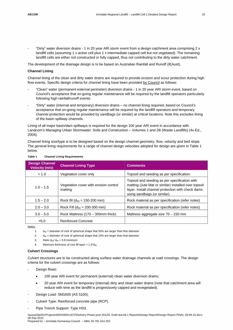
AECOM
Armidale Regional Landfill – Landfill Cell 1 Detailed Design Report
\\ausyd1fp001\Projects\600X\60011672\Delivery Phase post 2012\5. Draft docs\6.1 Reports\Design Report\Design Report FINAL 28-09-15.docx 28-Sep-2015 Prepared for – Armidale Dumaresq Council – ABN: 63 781 014 253
15
- “Dirty” water diversion drains - 1 in 20 year ARI storm event from a design catchment area comprising 2 x landfill cells (assuming 1 x active cell plus 1 x intermediate capped cell but not vegetated). The remaining landfill cells are either not constructed or fully capped, thus not contributing to the dirty water catchment.
The development of the drainage design is to be based on Australian Rainfall and Runoff (IEAust).
Channel Lining
Channel lining of the clean and dirty water drains are required to provide erosion and scour protection during high flow events. Specific design criteria for channel lining have been provided by Council as follows:
- “Clean” water (permanent external perimeter) diversion drains - 1 in 20 year ARI storm event, based on Council’s acceptance that on-going regular maintenance will be required by the landfill operators particularly following high rainfall/runoff events.
- “Dirty” water (internal and temporary) diversion drains – no channel lining required, based on Council’s acceptance that on-going regular maintenance will be required by the landfill operators and temporary channel protection would be provided by sandbags (or similar) at critical locations. Note this excludes lining of the basin spillway channels.
Lining of all major basin/dam spillways is required for the design 100 year ARI event in accordance with Landcom‘s Managing Urban Stormwater: Soils and Construction – Volumes 1 and 2B (Waste Landfills) (4th Ed., 2004).
Channel lining size/type is to be designed based on the design channel geometry, flow, velocity and bed slope. The general lining requirements for a range of channel design velocities adopted for design are given in Table 1 below. Table 1 Channel Lining Requirements
Design Channel Velocity (m/s) Channel Lining Type Comments
< 1.0 Vegetation cover only Topsoil and seeding as per specification.
1.0 – 1.5 Vegetation cover with erosion control matting
Topsoil and seeding as per specification with matting (Jute Mat or similar) installed over topsoil layer. Install channel protection with check dams using sandbags (or similar).
1.5 – 2.0 Rock fill (d50 = 150-200 mm) Rock material as per specification (refer notes)
2.0 – 3.0 Rock Fill (d50 = 200-300 mm) Rock material as per specification (refer notes)
3.0 – 5.0 Rock Mattress (170 – 300mm thick) Mattress aggregate size 70 – 150 mm
>5.0 Reinforced Concrete Notes:
1. d50 = diameter of rock of spherical shape that 50% are larger than that diameter 2. d90 = diameter of rock of spherical shape that 10% are larger than that diameter 3. Ratio d50/ d90 = 0.8 minimum 4. Minimum thickness of rock fill layer = 1.5*d50
Culvert Crossings
Culvert structures are to be constructed along surface water drainage channels at road crossings. The design criteria for the culvert crossings are as follows:
- Design flows:
• 100 year ARI event for permanent (external) clean water diversion drains;
• 20 year ARI event for temporary (internal) dirty and clean water drains (note that catchment area will reduce with time as the landfill is progressively capped and revegetated).
- Design Load: SM1600 (AS 5100).
- Culvert Type: Reinforced concrete pipe (RCP).
- Pipe Trench Support: Type HS3.

AECOM
Armidale Regional Landfill – Landfill Cell 1 Detailed Design Report
\\ausyd1fp001\Projects\600X\60011672\Delivery Phase post 2012\5. Draft docs\6.1 Reports\Design Report\Design Report FINAL 28-09-15.docx 28-Sep-2015 Prepared for – Armidale Dumaresq Council – ABN: 63 781 014 253
16
- Pipe Cover: 600mm minimum.
Clean Water Drain Outlet Apron
Clean water would be discharged into an outlet apron area, to reduce potential soil erosion and scouring during high flow events, prior discharging into the existing unnamed watercourse downstream of the site. The apron is to be designed to limit outlet velocities to less than 1.5m/s for flows up to the 100 year ARI event.
5.9 Internal Access Roads Internal access roads within the site are required as follows:
- Temporary access road from the entrance gatehouse/weighbridge to the landfill Cell 1 site;
- Landfill cell perimeter road, providing access into the landfill cell waste area.
The adopted design criteria for the internal access roads are as follows:
- Estimated number of heavy (waste) vehicles entering/exiting the site is 4 to 6 per day (based on Environmental Assessment Report).
- Design vehicle for the heavy (waste) trucks for turn path analysis - AUSTROADS standard 12.5m single unit truck.
- Design pavement subgrade CBR of 3% min (refer Section 4.2).
- An adopted maximum design speed for internal roads of 25km/hr.
- Minimum roadway width of 5m for two-way traffic.
- Maximum road longitudinal grade of 10%, with a 3% nominal transverse cross-fall.
- Council has requested that all internal roads be unsealed and acceptance that on-going regular maintenance (surface regrading and pothole repair) will be required by the landfill operators.
5.10 Leachate Water Pipelines 5.10.1 Leachate Extraction Pipeline
A leachate extraction pipeline is required to transfer leachate from the leachate sump within the landfill cell to the Leachate Pond.
A nominal leachate extraction rate of 6 L/s has been adopted for the pipeline design allowing the following criteria:
- Leachate extraction from approx. 6.0 ha of 2 x landfill cells (assuming 1 x active cell plus 1 x intermediate capped cell but not vegetated with remaining landfill cells not constructed or fully capped);
- A maximum daily leachate generation rate of 520m3/day (or approx. 6 L/s) during landfilling operations based upon leachate generation rates as determined by hydraulic modelling and water balance calculations - refer AECOM’s Water and Leachate Management Plan.
5.10.2 Leachate Return Pipeline
A leachate return pipeline is required to transfer leachate from the Leachate Pond to the landfill cell for irrigation onto, or re-injection into, the active landfill cell area.
A nominal leachate return rate of 5 L/s has been adopted for the pipeline design allowing the Leachate Pond storage volume (approx. 12ML) to be emptied in approximately 1 month, if required.

AECOM
Armidale Regional Landfill – Landfill Cell 1 Detailed Design Report
\\ausyd1fp001\Projects\600X\60011672\Delivery Phase post 2012\5. Draft docs\6.1 Reports\Design Report\Design Report FINAL 28-09-15.docx 28-Sep-2015 Prepared for – Armidale Dumaresq Council – ABN: 63 781 014 253
17
6.0 Cell 1 Landfill Design
6.1 Cell 1 Landfill The Cell 1 base layout and extent of the Cell 1 landfill (top of clay liner) is shown in Appendix B.
The main features of the Cell 1 landfill are summarised below:
- The cell base (floor and walls) dimensions are approximately 250m wide by 150m long, occupying a surface area of approximately 3ha.
- The cell landfill area is surrounded by a low perimeter earth bund (1 m minimum height above the cell base level) to effectively contain the waste and any stored leachate water. The bund also provides for an anchor trench for the leachate barrier system.
- The cell is to be split into 2 separate sub-cells (sub-cells A and B) to better manage the landfill waste placement and management of leachate and dirty water during initial operations.
- The base of the landfill leachate barrier is excavated a nominal 1.5m below ground to source suitable clay fill materials for the leachate barrier’s clay liner layer. The surface levels of the base will range from approximately RL 982m to RL 997m, with a central gully that maintains surface runoff towards the north. Some minor regrading of the landfill base will be required to ensure drainage to the leachate sump (low-point).
- The final top waste surface will grade from the south to the north at a minimum 5% nominal grade. The surface levels will range from approximately RL 1002m to RL 995m, with a central ridge to allow surface runoff to be diverted away from the active (northern) waste batter face. The resultant maximum waste depth is approximately 14m. The external outer batters of the final capped surface will have slopes no greater than 25% (or 4H:1V).
6.2 Leachate Barrier System The leachate barrier system is designed in compliance In compliance with the Conditions of Approval and EPA Benchmark Technique Number 1. The leachate barrier (clay liner) layout and extents is shown in the in Appendix B, and the main design features and details are summarised below:
- A compacted clay liner 900mm thick with a minimum in-situ co-efficient of permeability of less than 10-9 m/s covering the entire floor and walls of the cell; and
- An overlying 2mm HDPE geomembrane liner with a minimum co-efficient of permeability of less than 10-14 m/s covering the entire floor and walls of the cell.
The cell floor (prior to construction of the leachate barrier) will be excavated to a nominal depth of 1.5m below ground to source suitable clay fill materials for the leachate barrier clay liner and the perimeter embankments. Some regrading of the cell floor will also be required to maintain a minimum 1% longitudinal fall of the leachate collection pipes (refer Section 6.3). The resultant transverse grade to the leachate sump will range from 7% to 20% (10% on average).
The HDPE liner on the perimeter embankment batters (3H:1V) will be textured on both sides to in increase friction of the underlying and overlying layers and reduce load on the anchor trenches. The HDPE liner on the cell floor will be smooth on both sides.
The material specifications and the construction and QA/QC requirements for the leachate barrier system for the landfill cell is provided in the Technical Specification for the works. The Clay Fill material for the compacted clay liner is to comply with the criteria provided in the table below.

AECOM
Armidale Regional Landfill – Landfill Cell 1 Detailed Design Report
\\ausyd1fp001\Projects\600X\60011672\Delivery Phase post 2012\5. Draft docs\6.1 Reports\Design Report\Design Report FINAL 28-09-15.docx 28-Sep-2015 Prepared for – Armidale Dumaresq Council – ABN: 63 781 014 253
18
Table 2 Clay Fill Material Compliance Criteria
Material Property Minimum Maximum Test
Coefficient of Permeability - 1x10⁻⁹ m/s AS1289 6.7.1
Liquid Limit 25 65* AS1289 3.1.1
Plasticity Index 15 50 AS1289 3.2.1
Moisture content when placed at 95% SOMC 0% wet of OMC 3% wet of OMC AS1289 2.1.1
Particle Size Distribution
− Maximum particle size
− Soil content passing 19 mm sieve
− Soil content passing 75µmm sieve
− Soil content passing 2µmm sieve
-
70%
40%
15%
50 mm
100%
-
-
AS1289 3.6.1 and AS1289 3.6.3
Organic Content - <=2% AS1289 4.1.1
Emerson Class ≥4 - AS1289.3.8.1
Cation Exchange Capacity 10 mEq/100g
Classification SC, CI,CH AS 1726
The clay fill material is to be selectively sourced from in-situ excavations of the landfill cell. Geotechnical testing of these soils indicates that the above material property requirements can be met (refer Section 4.3). The testing and use of non-dispersive material (Emerson Class ≥4) is a requirement for the clay liner material to address the issue of any dispersive soil in surface soil horizons specified in the Conditions of Approval (refer Section5.3).
6.3 Leachate Collection and Conveyance System The leachate collection system will consist of a drainage layer and collection pipes installed above the leachate barrier system to effectively drain leachate to a collection sump.
The leachate collection system is designed in compliance with the Conditions of Approval and EPA Benchmark Technique Number 2 (refer Section 5.4). The leachate collection system layout and details are shown in Appendix B, and the main design features and details are summarised below:
- The base of the landfill will be graded so that the leachate will be directed to the leachate collection pipes and the sump (refer Section 6.2).
- A 300mm thick drainage gravel layer covering the entire floor and walls of the cell with a co-efficient of permeability not less than 10-3 m/s with a protection geotextile below and a filter geotextile above gravel layer.
- A network of slotted leachate collection pipes within the cell’s drainage gravel layer as follows:
• 250mm ND PN16 PE100 (polyethylene) main leachate collection pipelines running along the full length (within the gully) of the cell; and
• A series of 200mm ND PN16 PE100 lateral leachate collector pipelines running across width the cell (at 30m nominal spacing) and along the base of the northern perimeter bund.
- Access for cleanout via flushing points located along the perimeter bund at each end of the main leachate collection pipes.
- The leachate collection pipes will gravity drain to a leachate collection sump (3m long x 3m wide x 1m deep).
- Pump-out from the leachate collection sump to the Leachate Pond via a 110ND PE100 PN8 extraction main. The leachate extraction pump will be housed in a 315ND PE100 PN16 (solid) riser pipe from the leachate

AECOM
Armidale Regional Landfill – Landfill Cell 1 Detailed Design Report
\\ausyd1fp001\Projects\600X\60011672\Delivery Phase post 2012\5. Draft docs\6.1 Reports\Design Report\Design Report FINAL 28-09-15.docx 28-Sep-2015 Prepared for – Armidale Dumaresq Council – ABN: 63 781 014 253
19
sump to the landfill perimeter bund crest. The leachate extraction main has been sized to for a maximum extraction rate of 10 L/s from the landfill (assumed from a maximum of 2 active/interim capped cells at any one time during operations).
Leachate Collection Pipe Sizing
The size of the main leachate collection pipeline was determined based on the following design criteria:
- A maximum instantaneous leachate inflow rate to the leachate collection layer of 70 L/s (based on leachate generation and water balance modelling – refer Water and Leachate Management Plan, AECOM, 2015).
- An average pipe grade of 9%.
Based on the above, a 200mm minimum internal diameter pipe is required.
Structural stability calculations for the slotted leachate pipelines were also undertaken. These calculations considered requirements for initial stiffness, as well as full service load requirements for ring deflection, wall stress, and ring buckling. These calculations allow for stresses induced by waste placement of up to 14m above the pipe.
The resultant main leachate collection pipes will have the following characteristics:
- A 250ND ND PE100 PN8 pipes (203mm internal diameter).
- Pipe wall thickness approximately 23mm.
- Slotted perforation diameter 10mm, with four holes at each perforated section.
- Perforated sections spaced at 300mm centres.
The resultant lateral leachate collection pipes will have the following characteristics:
- A 200ND ND PE100 PN8 pipes (162mm internal diameter ie. greater than 150mm min).
- Pipe wall thickness approximately 18mm.
- Slotted perforation diameter 10mm, with four holes at each perforated section.
- Perforated sections spaced at 300mm centres.
6.4 Leachate Storage Pond The Leachate Pond will collect and store leachate water from the landfill via a leachate gravity main from the landfill’s leachate collection system. The leachate pond will be sized based upon leachate generation rates as determined by hydraulic modelling and water balance calculations - refer Water and Leachate Management Plan, AECOM 2015. The Leachate pond is located downstream of the final landfill footprint and immediately upstream of the Sedimentation Basin (refer Section 6.5).
The Leachate Pond design is in compliance with the Conditions of Approval and EPA Benchmark Technique Number 2 (refer Section 5.5). The Leachate Pond layout is shown in Appendix A and the main design features and details summarised below:
- Perimeter bund walls at crest RL 963.80m, constructed using compacted clay fill materials.
- A spillway at RL 963.00m providing a total leachate storage volume of 14.7ML.
- A maximum operating level at RL 962.60m, providing a total freeboard depth of 400mm to contain a 100 year ARI, 3 day rainfall event (225mm) and an additional 150mm freeboard for wave action.
- The internal floor and batters of the pond to be lined as follows:
• a compacted clay liner 900mm thick with a minimum in-situ co-efficient of permeability of less than 10-9 m/s covering the entire floor and walls of the pond; and
• an overlying 2mm HDPE geomembrane liner with a minimum co-efficient of permeability of less than 10-14 m/s covering the entire floor and walls of the pond.
- A 1m wide concrete lined emergency overflow spillway channel located down the pond embankment with discharge into the downstream Sedimentation Basin.

AECOM
Armidale Regional Landfill – Landfill Cell 1 Detailed Design Report
\\ausyd1fp001\Projects\600X\60011672\Delivery Phase post 2012\5. Draft docs\6.1 Reports\Design Report\Design Report FINAL 28-09-15.docx 28-Sep-2015 Prepared for – Armidale Dumaresq Council – ABN: 63 781 014 253
20
- Inflow from the Cell 1 landfill leachate collection sump (refer Section 6.4) to the Leachate Pond via a 250ND PE (SDR26) gravity pipeline (internal diameter = 230mm).
Based on the above, the resultant storage curve for the Leachate Pond is provided in Appendix C.
The material specifications and the construction and QA/QC requirements for the leachate barrier system for the Leachate Pond is provided in the Technical Specification. The Clay Fill material for the compacted clay liner is to comply with the criteria provided in the Table 2 above.
Operation
The stored leachate water within the pond is to be managed and disposed by way of:
- Surface evaporation;
- Irrigation on to an active landfill cell;
- Re-injection into an active or capped landfill cell; and
- Transportation to a facility licensed to accept such waste.
The leachate water storage level within the pond should be monitored on a regular basis by a depth marker, or similar. Depending on the depth, the appropriate rate and method of disposal should be adopted by the landfill operators.
An automatic shut-off valve is to be located on the leachate gravity main (downstream of the landfill cell) that will be used to control leachate outflows from the landfill and also provide emergency shut-off in emergency conditions when the Leachate Pond reaches maximum operating capacity. This could consist of a water level float valve or sensor at the Leachate Pond which would activate the valve by a telemetry system via a control cabinet.
Maintenance
The Sedimentation Basin should be inspected on a regular, on-going scheduled basis.
The maintenance program should include the following minimum tasks:
- Any sludge is removed if build up exceeds approximately 300mm.
- Inspect and repair the HDPE liner if required.
6.5 Sedimentation Basin The Sedimentation Basin has been designed to capture and store all runoff from the landfill and other disturbed areas within the site during operation for treatment prior to release or re-use on site. The basin is located immediately downstream of the Leachate Pond and upstream of the Dry Basin (refer Section 6.6).
The design catchment area of the Sedimentation Basin is approximately 11.0 ha which comprises the following:
- Approx. 6.0 ha of 2 x landfill cells (assuming 1 x active cell plus 1 x intermediate capped cell but not vegetated with remaining landfill cells not constructed or fully capped);
- Approx. 5.0 ha of disturbed area downstream of landfill (stockpile areas, office, carpark/hardstand area).
Based on the above and the design criteria (refer Section 5.6), the results for the minimum required settling and sediment zone volumes for the Sedimentation Basin are shown in the table below. Table 3 Minimum Sedimentation Basin Capacity
Storage Component Minimum Required Storage Volume (m3)
Sediment Zone Volume (m3) 1,500
Settling Zone Volume (m3) 3,750
Total Volume (m3) 5,250
The Sedimentation Basin design is in compliance with the Conditions of Approval and EPA Benchmark Technique Number 3 (refer Section 5.6). The Sedimentation Basin layout is shown in Appendix A and the main design features and details are summarised below:
AECOM
Armidale Regional Landfill – Landfill Cell 1 Detailed Design Report
\\ausyd1fp001\Projects\600X\60011672\Delivery Phase post 2012\5. Draft docs\6.1 Reports\Design Report\Design Report FINAL 28-09-15.docx 28-Sep-2015 Prepared for – Armidale Dumaresq Council – ABN: 63 781 014 253
21
- Perimeter bund walls at crest RL 959.50m, constructed using compacted embankment fill materials.
- A spillway at RL 958.50m providing a total storage volume of 5,400m3.
- A sediment storage zone (2.0m depth) up to RL 957.00m providing a storage volume of 1,600m3.
- An overlying settling zone (1.5m depth) up to RL 958.50m (spill level) providing a storage volume of 3,750m3.
- The internal storage floor and bund wall surfaces to be lined with 300mm of embankment fill or in-situ material.
- An embankment cut-off key (1m min depth) to control shallow subsurface seepages.
- A 3m wide (concrete lined) emergency overflow spillway channel located down the pond embankment with discharge into the downstream Dry Basin.
- Topsoiling and seeding the downstream embankment batter.
Based on the above, the resultant storage curve for the Sedimentation Basin is provided in Appendix C.
Operation
The stored water and sediment level within the pond should be monitored and tested on a regular basis, particularly following major rainfall events. Height pegs or markers are to be installed and maintained within the basin to indicate the maximum level of the sediment zone. When the markers indicate that the sediment zone has reached (or is reaching) full capacity, then stored sediments would need to be removed/disposed to maintain the minimum water storage capacity within the basin.by a depth marker, or similar. Depending on the depth, the appropriate rate and method of disposal should be adopted by the landfill operators.
Water in the settling zone should be pumped out within the time period adopted in the design of the basin provided that the nominated water quality targets have been met (ie. TSS not exceeding 50 mg/L). A period of 5 days has been allowed for in the design of this basin but this can be increased to up to 20 days if site conditions allow.
If the water stored in the Sedimentation Basin has a TSS reading of higher than 50mg/L after sufficient time has elapsed to allow natural settling, the water would need to be treated by a flocculation/coagulation treatment system. Stored water within the Sedimentation Basin would be pumped through the treatment system. Treated water from the Sedimentation Basin would then be discharged to the clean water drain or used as a potential source of non-potable water during landfilling operations, such as the wheel wash facility, washing, dust suppression etc. In the event of emergency overflow from the Sedimentation Basin, water will also be fully contained in the Dry Basin.
Maintenance
The Sedimentation Basin should be inspected after all significant rainfall events and on a scheduled basis.
The maintenance program should include the following minimum tasks:
- Sediment to be removed if the design capacity or less remains in the settling zone.
- Dispose of any collected sediments from Sedimentation Basin to the landfill.
6.6 Dry Basin The Dry Basin has been designed to capture all runoff from the landfill and other disturbed areas within the site upstream of the basin during operation. The basin is to be located downstream of the Sedimentation Basin and Leachate Pond.
The design catchment area of the Sedimentation Basin is 15.7 ha which comprises the following:
- Approx. 6.0 ha of 2 x landfill cells (assuming 1 x active cell plus 1 x intermediate capped cell but not vegetated with remaining landfill cells not constructed or fully capped);
- Approx. 9.7 ha of disturbed area upstream of Dry Basin (stockpile areas, office, carpark/hardstand area including Sedimentation Basin and Leachate Pond).

AECOM
Armidale Regional Landfill – Landfill Cell 1 Detailed Design Report
\\ausyd1fp001\Projects\600X\60011672\Delivery Phase post 2012\5. Draft docs\6.1 Reports\Design Report\Design Report FINAL 28-09-15.docx 28-Sep-2015 Prepared for – Armidale Dumaresq Council – ABN: 63 781 014 253
22
For a design catchment area of approximately 15.7ha, a minimum effective storage capacity of 35.4ML is required to store the design 100 year ARI, 3 day rainfall event (225mm).
The Dry Basin design is in compliance with the Conditions of Approval and criteria in Section 5.7. The basin layout is shown in Appendix A and the main design features and details are summarised below:
- Embankment at crest RL 958.00m constructed using compacted embankment fill materials.
- A spillway at RL 957.10m providing, a total storage volume of 36.3ML.
- A maximum operation storage level at RL 953.60m, providing an effective storage volume of 35.5ML.
- The internal storage floor and bund wall surfaces to be lined with 300mm of embankment fill or in-situ material.
- An embankment cut-off key (1m min depth) to control shallow subsurface seepages.
- A 5m wide (rock fill lined) overflow spillway channel located down the pond embankment with discharge into the downstream clean water diversion drain.
- Topsoiling and seeding the downstream embankment batter.
- Provision of a 300ND RCP underflow pipeline (via a downstream shut-off valve) to effectively gravity drain the basin storage down to the maximum operation level (in a nominal 3 day period) with discharge to the Outlet Dissipation Basin (refer Section 0).
Based on the above, the resultant storage curve for the Dry Basin is provided in Appendix C.
Operation
The stored water level within the pond should be monitored and tested on a regular basis, particularly following major rainfall events. Stored water is to be disposed by:
- Gravity drainage via the underflow pipeline; and
- Pump-out for use as a potential source of non-potable water during landfilling operations, such as the wheel wash facility, washing, dust suppression etc.
Under normal operating conditions, any stored runoff water above the maximum operation level should be gravity drained via the underflow pipeline (by opening the valve) within a nominal 3 to 5 day period, provided that the nominated water quality targets have been met (ie. TSS not exceeding 50 mg/L). If adequate water quality cannot be provided within this time, then stored water should be pumped to the Sedimentation Basin for treatment and subsequent disposal or re-use.
Maintenance
The Dry Basin should be inspected after all significant rainfall and on a scheduled basis.
The maintenance program should include the following minimum tasks:
- Inspection after all significant rainfall events and debris to be removed.
- Sediment to be removed periodically.
- Dispose of any collected sediments from the Dry Basin to the landfill.
- Inspect outlet pipe for blockages.
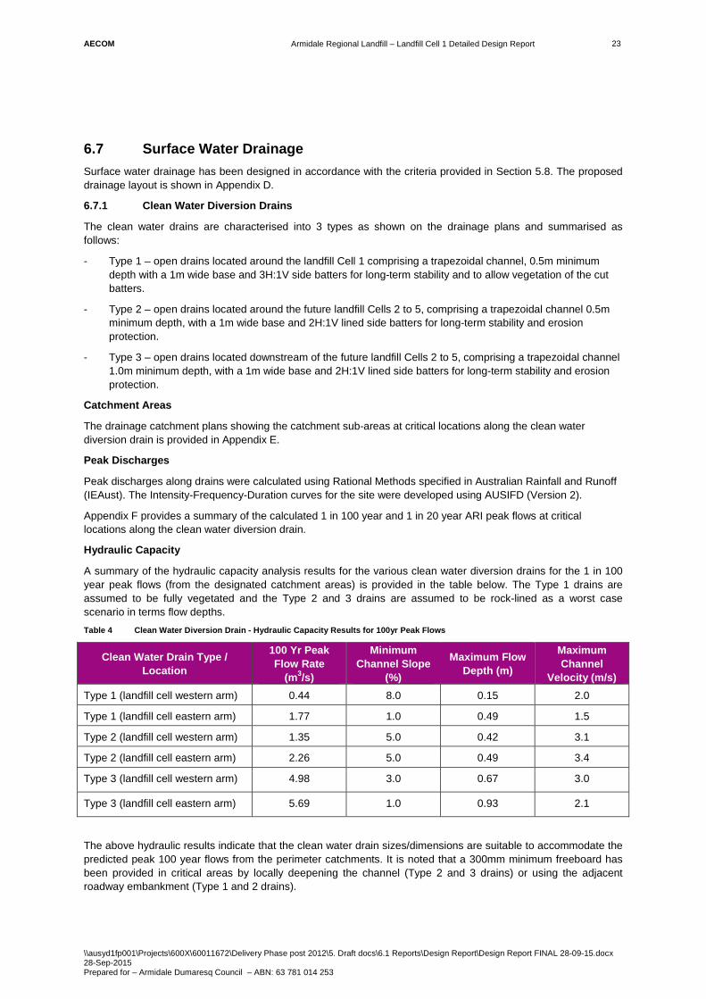
AECOM
Armidale Regional Landfill – Landfill Cell 1 Detailed Design Report
\\ausyd1fp001\Projects\600X\60011672\Delivery Phase post 2012\5. Draft docs\6.1 Reports\Design Report\Design Report FINAL 28-09-15.docx 28-Sep-2015 Prepared for – Armidale Dumaresq Council – ABN: 63 781 014 253
23
6.7 Surface Water Drainage Surface water drainage has been designed in accordance with the criteria provided in Section 5.8. The proposed drainage layout is shown in Appendix D.
6.7.1 Clean Water Diversion Drains
The clean water drains are characterised into 3 types as shown on the drainage plans and summarised as follows:
- Type 1 – open drains located around the landfill Cell 1 comprising a trapezoidal channel, 0.5m minimum depth with a 1m wide base and 3H:1V side batters for long-term stability and to allow vegetation of the cut batters.
- Type 2 – open drains located around the future landfill Cells 2 to 5, comprising a trapezoidal channel 0.5m minimum depth, with a 1m wide base and 2H:1V lined side batters for long-term stability and erosion protection.
- Type 3 – open drains located downstream of the future landfill Cells 2 to 5, comprising a trapezoidal channel 1.0m minimum depth, with a 1m wide base and 2H:1V lined side batters for long-term stability and erosion protection.
Catchment Areas
The drainage catchment plans showing the catchment sub-areas at critical locations along the clean water diversion drain is provided in Appendix E.
Peak Discharges
Peak discharges along drains were calculated using Rational Methods specified in Australian Rainfall and Runoff (IEAust). The Intensity-Frequency-Duration curves for the site were developed using AUSIFD (Version 2).
Appendix F provides a summary of the calculated 1 in 100 year and 1 in 20 year ARI peak flows at critical locations along the clean water diversion drain.
Hydraulic Capacity
A summary of the hydraulic capacity analysis results for the various clean water diversion drains for the 1 in 100 year peak flows (from the designated catchment areas) is provided in the table below. The Type 1 drains are assumed to be fully vegetated and the Type 2 and 3 drains are assumed to be rock-lined as a worst case scenario in terms flow depths. Table 4 Clean Water Diversion Drain - Hydraulic Capacity Results for 100yr Peak Flows
Clean Water Drain Type / Location
100 Yr Peak Flow Rate
(m3/s)
Minimum Channel Slope
(%)
Maximum Flow Depth (m)
Maximum Channel
Velocity (m/s) Type 1 (landfill cell western arm) 0.44 8.0 0.15 2.0
Type 1 (landfill cell eastern arm) 1.77 1.0 0.49 1.5
Type 2 (landfill cell western arm) 1.35 5.0 0.42 3.1
Type 2 (landfill cell eastern arm) 2.26 5.0 0.49 3.4
Type 3 (landfill cell western arm) 4.98 3.0 0.67 3.0
Type 3 (landfill cell eastern arm) 5.69 1.0 0.93 2.1
The above hydraulic results indicate that the clean water drain sizes/dimensions are suitable to accommodate the predicted peak 100 year flows from the perimeter catchments. It is noted that a 300mm minimum freeboard has been provided in critical areas by locally deepening the channel (Type 2 and 3 drains) or using the adjacent roadway embankment (Type 1 and 2 drains).

AECOM
Armidale Regional Landfill – Landfill Cell 1 Detailed Design Report
\\ausyd1fp001\Projects\600X\60011672\Delivery Phase post 2012\5. Draft docs\6.1 Reports\Design Report\Design Report FINAL 28-09-15.docx 28-Sep-2015 Prepared for – Armidale Dumaresq Council – ABN: 63 781 014 253
24
Channel Lining Requirements
Channel lining of the clean water diversions drains are required to provide erosion and scour protection during high flow events (refer Section 5.8). A summary of the channel lining hydraulic analysis results for the various clean water diversion drains for the 1 in 20 year peak flows (from the designated catchment areas) is provided in the table below. The table also provides the required channel lining protection type in accordance with Table 1 – Section 5.8, based on the design peak channel flow velocities. Table 5 Clean Water Diversion Drain - Hydraulic Channel Lining Results for 20yr Peak Flows
Clean Water Drain Type / Location
20 Yr Peak Flow Rate
(m3/s)
Maximum Channel
Slope (%)
Maximum Flow Depth
(m)
Maximum Channel
Velocity (m/s)
Channel Lining Requirement
Type 1 (landfill cell western arm)
0.24 8.0 0.11 1.5 Topsoil and seeding with erosion control matting and install channel check dams using sandbags (or similar).
Type 1 (landfill cell eastern arm)
1.22 1.0 0.41 1.3 Topsoil and seeding with erosion control matting and install channel check dams using sandbags (or similar).
Type 2 (landfill cell western arm)
0.77 5.0 0.23 2.3 Rock Fill (d50 = 200-300 mm) or concrete lined
Type 2 (landfill cell eastern arm)
1.91 6.5 0.35 3.2 Rock Mattress (170mm thick) or concrete lined
Type 3 (landfill cell western arm)
3.00 3.0 0.54 2.7 Rock Fill (d50 = 200-300 mm) or concrete lined
Type 3 (landfill cell eastern arm)
3.22 5.0 0.49 3.3 Rock Mattress (170mm thick) or concrete lined
The above channel lining result indicates that the Type 2 and 3 clean water diversion drains (ie. downstream of Landfill cell 1) require either rock or concrete lining to provide erosion and scour protection during high flow events. Discussions with Council have indicated a preference of concrete lining (due to costs) and therefore has been adopted in the design.
Existing Farm Dams
The two existing farm dams located downstream of the landfill cell will be maintained for temporary storage and water quality treatment prior to discharge to the perimeter clean water drainage system (note this catchment is to be maintained undisturbed during landfilling operations).
6.7.2 Dirty Water Drains
An internal (temporary) dirty water diversion drain is the constructed for the Landfill Cell perimeter drain to the downstream Sedimentation Basin. The drain is to comprise a trapezoidal channel 1.0m minimum depth, with a 1m wide base and 2H:1V side batters for short-term stability.
The dirty drains are to be unlined (refer Section 5.8) based on Council’s acceptance that on-going regular maintenance will be required by the landfill operators and temporary channel protection would be provided by sandbags (or similar) at critical locations.
6.7.3 Road Culvert Crossings
Two road culvert crossings are required as shown in the drainage layout plan in Appendix D and as described below:
- Culvert No. 1 - located at landfill perimeter road crossing along dirty water drain downstream of landfill Cell 1
- Culvert No. 2 - located at landfill access road crossing along temporary clean water drain, downstream of the existing farm dam.

AECOM
Armidale Regional Landfill – Landfill Cell 1 Detailed Design Report
\\ausyd1fp001\Projects\600X\60011672\Delivery Phase post 2012\5. Draft docs\6.1 Reports\Design Report\Design Report FINAL 28-09-15.docx 28-Sep-2015 Prepared for – Armidale Dumaresq Council – ABN: 63 781 014 253
25
The culvert capacity hydraulic capacities were analysed using the CulvertMaster (Version 3.3) software program. The results of the analysis for both culverts are summarised in the table below. Table 6 Culvert Hydraulic Analysis Results
Culvert Number
Culvert Pipe Type /Size
Peak Flow Rate (1 in 20
Yr ARI) (m3/s)
Culvert Slope (%)
Headwater Depth
(m)
Outlet Velocity (m/s)
Culvert No. 1 600 ND RCP 0.85 5.0 1.5 3.9
Culvert No. 2 900 ND RCP 1.47 0.5 1.3 2.7
A resultant 300mm minimum freeboard is provided to the road crest level for both culvert designs.
Inlet and outlet headwalls to be provided with rock rip-rap or concrete lining for erosion/scour protection.
The pipe strength class for both culverts were analysed using the Concrete Pipe Association’s PipeClass (Version 2.022) software program. For a minimum pipe cover of 600mm, Class 2 RCP is required for both culverts.
6.7.4 Clean Water Drain Outlets
The eastern arm of the Clean Water Diversion Drain is to outlet to Rock Apron to effectively reduce potential soil erosion and scouring (during high flow events) prior discharging into the existing unnamed watercourse downstream of the site.
The Rock Apron outlet width has been sized to limit outlet velocities to less than 1.5 m/s for flows up to the 100 year ARI event. For a 100 year peak flow at the apron outlet of 5.7 m3/s (refer Table 5 above) for an outlet apron width of 30m, the resultant outlet flow depth is approximately 0.13 m, with a corresponding outlet velocity of 1.4 m/s for a 2% outlet grade of the ground surface.
The western arm of the Clean Water Diversion Drain is to outlet directly into existing unnamed watercourse downstream of the site, and immediately upstream of the site access road culvert crossing. The drain outlet structure to the creek is to be designed by Council as part of the site access road works.
Maintenance
The maintenance program for the surface drainage infrastructure should include the following minimum tasks:
- Drains that have become blocked through sediment pollution, sand/spoil/soil being deposited in or too close to them are to be cleaned out when identified by inspection;
- Drains are to be checked to ensure operating as intended, in particular checking that:
No low points exist which can overtop in a large storm event;
Areas of erosion are repaired;
Rock rip-rap replaced/repaired as required;
Batter revegetation is progressing.
- Clean water diversion drains are to be inspected regularly to ensure no dirty water or leachate is entering the drains.
- Culvert inlet/outlet areas and energy dissipation basins are to be inspected regularly to ensure they are performing adequately and that there is no evidence of erosion.
6.8 Internal Access Roads The internal access roads have been designed in accordance with the criteria provided in Section 5.9. The road layout and details are shown in the site layout plan provided in Appendix A, and the main design features and details summarised below:
- Approximately 500m of landfill access road from the entrance site office to the landfill Cell 1 site.

AECOM
Armidale Regional Landfill – Landfill Cell 1 Detailed Design Report
\\ausyd1fp001\Projects\600X\60011672\Delivery Phase post 2012\5. Draft docs\6.1 Reports\Design Report\Design Report FINAL 28-09-15.docx 28-Sep-2015 Prepared for – Armidale Dumaresq Council – ABN: 63 781 014 253
26
- Approximately 800m of landfill perimeter access road, providing access around and into the landfill cell waste area.
The landfill access road pavement is to comprise the following compacted layers (as per Council’s access road design):
- 150mm thick base course (DGB20).
- 370mm thick subbase (DGS20)
The landfill perimeter access road pavement is to comprise the following compacted layers:
- 150mm thick base course (DGB20).
- 200mm thick subbase (DGS40)
In areas where the road pavement subgrade is weak (ie. CBR < 3), the subgrade may need to be stabilised (by gravel and geotextile, or similar) in accordance with the Technical Specification.
It is noted that Council has requested that all internal roads be unsealed and acceptance that on-going regular maintenance (surface regrading and pothole repair) will be required by the landfill operators.
6.9 Leachate Water Pipelines 6.9.1 Leachate Extraction Pipeline
The leachate return system been designed in accordance with the criteria provided in Section 5.10 for a design flow rate of approximately 6 L/s.
The main design features of the leachate extraction system would include:
- A submersible pump within the 315ND leachate sump riser pipe within Landfill Cell 1 (design by others).
- A 110ND PE100 PN8 rising main from the submersible pump to the Leachate Pond pump (500m nominal length) within a common trench with the leachate return main (refer below).
6.9.2 Leachate Return Pipeline
The leachate return pipeline has been designed in accordance with the criteria provided in Section 5.10, for a design flow rate of approximately 5 L/s.
The main design features of the leachate return system would include:
- A pontoon mounted intake pump (or similar) at the Leachate Pond (design by others).
- A 75ND PE100 PN8 rising main from the Leachate Pond pump to the landfill header tank (650m nominal length) within a common trench with the leachate gravity main.
- A temporary above-ground) header tank to be located on top of the active/capped landfill cell for irrigation or re-injection supply (design by others).

AECOM
Armidale Regional Landfill – Landfill Cell 1 Detailed Design Report
\\ausyd1fp001\Projects\600X\60011672\Delivery Phase post 2012\5. Draft docs\6.1 Reports\Design Report\Design Report FINAL 28-09-15.docx 28-Sep-2015 Prepared for – Armidale Dumaresq Council – ABN: 63 781 014 253
27
7.0 Construction
7.1 Drawings The list of final (for tender) design drawings to be issued are summarised in Table 7. Table 7 List of Final (For Tender) Design Drawings
Drawing No. Drawing Title
0011672-SHT-CI-0001 COVER SHEET AND DRAWING LIST
60011672-SHT-CI-0005 GENERAL NOTES
60011672-SHT-CI-0011 GENERAL ARRANGEMENT PLAN
60011672-SHT-CI-0012 CLEARING AND GRUBBING PLAN SHEET 1
60011672-SHT-CI-0013 CLEARING AND GRUBBING PLAN SHEET 2
60011672-SHT-CI-0016 SITE CLEARANCE AND TOPSOIL STRIPPING PLAN
60011672-SHT-CI-0017 MATERIAL STOCKPILE PLAN
60011672-SHT-CI-0018 EROSION AND SEDIMENT CONTROL PLAN
60011672-SHT-CI-0019 EROSION AND SEDIMENT CONTROL DETAILS
60011672-SHT-CI-0021 LANDFILL CELL 1 LAYOUT PLAN
60011672-SHT-CI-0022 LEACHATE STORAGE POND LAYOUT PLAN
60011672-SHT-CI-0023 SEDIMENTATION BASIN LAYOUT PLAN
60011672-SHT-CI-0024 DRY BASIN LAYOUT PLAN
60011672-SHT-CI-0025 CLEAN WATER DRAIN OUTLET ROCK APRON LAYOUT
60011672-SHT-CI-0031 CONTROL STRING PLAN SHEET 1
60011672-SHT-CI-0032 CONTROL STRING PLAN SHEET 2
60011672-SHT-CI-0041 EARTHWORKS LONGITUDINAL SECTIONS
60011672-SHT-CI-0042 EARTHWORKS LONGITUDINAL SECTIONS
60011672-SHT-CI-0051 EARTHWORKS LONGITUDINAL SECTIONS
60011672-SHT-CI-0052 EARTHWORKS LONGITUDINAL SECTIONS
60011672-SHT-CI-0053 EARTHWORKS LONGITUDINAL SECTIONS
60011672-SHT-CI-0055 EARTHWORKS CROSS SECTIONS
60011672-SHT-CI-0056 EARTHWORKS CROSS SECTIONS
60011672-SHT-CI-0061 ROAD LONGITUDINAL SECTIONS
60011672-SHT-CI-0062 ROAD LONGITUDINAL SECTIONS
60011672-SHT-CI-0063 ROAD LONGITUDINAL SECTIONS
60011672-SHT-CI-0064 ROAD LONGITUDINAL SECTIONS
60011672-SHT-CI-0071 ROAD CROSS SECTIONS
60011672-SHT-CI-0072 ROAD CROSS SECTIONS
60011672-SHT-CI-0073 ROAD CROSS SECTIONS
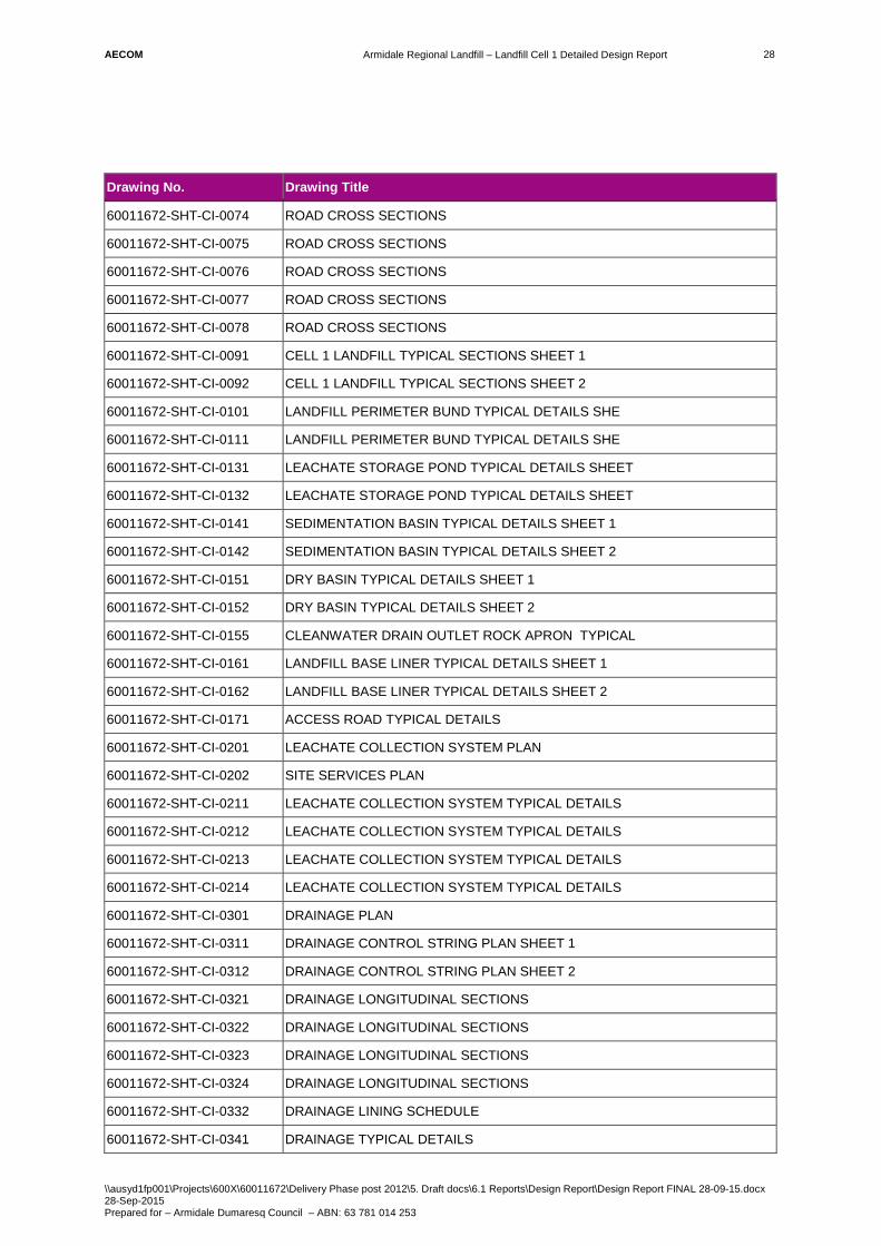
AECOM
Armidale Regional Landfill – Landfill Cell 1 Detailed Design Report
\\ausyd1fp001\Projects\600X\60011672\Delivery Phase post 2012\5. Draft docs\6.1 Reports\Design Report\Design Report FINAL 28-09-15.docx 28-Sep-2015 Prepared for – Armidale Dumaresq Council – ABN: 63 781 014 253
28
Drawing No. Drawing Title
60011672-SHT-CI-0074 ROAD CROSS SECTIONS
60011672-SHT-CI-0075 ROAD CROSS SECTIONS
60011672-SHT-CI-0076 ROAD CROSS SECTIONS
60011672-SHT-CI-0077 ROAD CROSS SECTIONS
60011672-SHT-CI-0078 ROAD CROSS SECTIONS
60011672-SHT-CI-0091 CELL 1 LANDFILL TYPICAL SECTIONS SHEET 1
60011672-SHT-CI-0092 CELL 1 LANDFILL TYPICAL SECTIONS SHEET 2
60011672-SHT-CI-0101 LANDFILL PERIMETER BUND TYPICAL DETAILS SHE
60011672-SHT-CI-0111 LANDFILL PERIMETER BUND TYPICAL DETAILS SHE
60011672-SHT-CI-0131 LEACHATE STORAGE POND TYPICAL DETAILS SHEET
60011672-SHT-CI-0132 LEACHATE STORAGE POND TYPICAL DETAILS SHEET
60011672-SHT-CI-0141 SEDIMENTATION BASIN TYPICAL DETAILS SHEET 1
60011672-SHT-CI-0142 SEDIMENTATION BASIN TYPICAL DETAILS SHEET 2
60011672-SHT-CI-0151 DRY BASIN TYPICAL DETAILS SHEET 1
60011672-SHT-CI-0152 DRY BASIN TYPICAL DETAILS SHEET 2
60011672-SHT-CI-0155 CLEANWATER DRAIN OUTLET ROCK APRON TYPICAL
60011672-SHT-CI-0161 LANDFILL BASE LINER TYPICAL DETAILS SHEET 1
60011672-SHT-CI-0162 LANDFILL BASE LINER TYPICAL DETAILS SHEET 2
60011672-SHT-CI-0171 ACCESS ROAD TYPICAL DETAILS
60011672-SHT-CI-0201 LEACHATE COLLECTION SYSTEM PLAN
60011672-SHT-CI-0202 SITE SERVICES PLAN
60011672-SHT-CI-0211 LEACHATE COLLECTION SYSTEM TYPICAL DETAILS
60011672-SHT-CI-0212 LEACHATE COLLECTION SYSTEM TYPICAL DETAILS
60011672-SHT-CI-0213 LEACHATE COLLECTION SYSTEM TYPICAL DETAILS
60011672-SHT-CI-0214 LEACHATE COLLECTION SYSTEM TYPICAL DETAILS
60011672-SHT-CI-0301 DRAINAGE PLAN
60011672-SHT-CI-0311 DRAINAGE CONTROL STRING PLAN SHEET 1
60011672-SHT-CI-0312 DRAINAGE CONTROL STRING PLAN SHEET 2
60011672-SHT-CI-0321 DRAINAGE LONGITUDINAL SECTIONS
60011672-SHT-CI-0322 DRAINAGE LONGITUDINAL SECTIONS
60011672-SHT-CI-0323 DRAINAGE LONGITUDINAL SECTIONS
60011672-SHT-CI-0324 DRAINAGE LONGITUDINAL SECTIONS
60011672-SHT-CI-0332 DRAINAGE LINING SCHEDULE
60011672-SHT-CI-0341 DRAINAGE TYPICAL DETAILS

AECOM
Armidale Regional Landfill – Landfill Cell 1 Detailed Design Report
\\ausyd1fp001\Projects\600X\60011672\Delivery Phase post 2012\5. Draft docs\6.1 Reports\Design Report\Design Report FINAL 28-09-15.docx 28-Sep-2015 Prepared for – Armidale Dumaresq Council – ABN: 63 781 014 253
29
Drawing No. Drawing Title
60011672-SHT-CI-0351 DRAINAGE CULVERT LONGITUDINAL SECTIONS
7.2 Technical Specification A Technical Specification will be prepared which details the works for the construction of the Cell 1 landfill and associated ancillary works including landfill barrier works, leachate collection, earthworks, road works, stormwater drainage, and pipe work.
The scope of work to be undertaken will be indicated on the drawings and include the following main items:
- Site establishment.
- Topsoil stripping and stockpiling.
- Site clearing and grubbing.
- Excavation (and temporary stockpile) and re-profiling of existing landfill surface to achieve the landfill base liner and storage basin subgrade levels.
- Subgrade preparation works.
- Construction of a low permeability landfill base liner comprising clay fill and HDPE layers.
- Construction of a landfill leachate collection system comprising slotted PE pipework, drainage gravel and geotextile layers.
- Construction of a Leachate Storage Pond using embankment fill materials including a low permeability base liner comprising clay fill and HDPE layers.
- Installation of leachate (PE) gravity and rising mains from the landfill to the Leachate Pond.
- Construction of a Sedimentation Basin and Dry Basin using embankment fill materials.
- Construction of basin inlet channels, overflow spillways and outlet dissipation structure.
- Construction of stormwater (clean and dirty water) drainage channels with rock rip-rap lining where required.
- Construction of landfill perimeter and access road formations and gravel pavements.
- Topsoiling and vegetation of drainage channels and embankment batters, as required.
- Site clean-up and restoration works.
7.3 Quality Control and Assurance Testing 7.3.1 Construction Quality Control Testing
A Contractor will be is responsible for the delivery of the whole of the construction works included in the Contract Documents.
The Contractor will have the following CQC responsibilities:
- Manage and oversee all QA/QC testing in accordance with the Technical Specification and Construction Quality Assurance Plan (CQAP) for the Works (provided by the Principal).
- Providing details of all relevant Quality Control Data arising from the manufacture and supply of the materials to be incorporated in the Works.
- Ensuring that all personnel engaged in the Works are competent suitably experienced and fully briefed on each aspect of their assigned tasks.
- Ensuring that all plant and machinery comply with all regulatory requirements, can undertake the proposed Works efficiently and are properly maintained and operating within required tolerances
- Undertaking the works in accordance with the requirements detailed in the Contract Documents and the Technical Specification.

AECOM
Armidale Regional Landfill – Landfill Cell 1 Detailed Design Report
\\ausyd1fp001\Projects\600X\60011672\Delivery Phase post 2012\5. Draft docs\6.1 Reports\Design Report\Design Report FINAL 28-09-15.docx 28-Sep-2015 Prepared for – Armidale Dumaresq Council – ABN: 63 781 014 253
30
- Provide a Construction Verification Report for all aspects relating to the geotechnical and material parameters and testing required in this Specification.
A Geotechnical Testing Authority (GTA) will be appointed by the Contractor and approved by the Site Superintendent and CQA Engineer, and be responsible for conducting all CQC testing as outlined in in the Technical Specification and the CQAP. Testing shall be in accordance with AS3798-2007 Level 1 Sampling and Testing.
7.3.2 Construction Quality Assurance Testing
A Construction Quality Assurance Plan (CQAP) has been developed in conjunction with this project and will be implemented by the Principal to check that the Works are undertaken in a manner that demonstrates compliance with the Contract Documents.
The Principal will engage an independent organisation or person (ie. CQA Engineer) under contract to the Principal, who will conduct additional independent Quality Assurance (QA) monitoring, observation, testing and documentation on behalf of the Principal. The Contractor shall cooperate fully with the Superintendent and all CQA representatives during any independent CQA sampling, testing, and certification and shall assure, at all times, safe access to the Works for the purpose of monitoring, observation, and CQA implementation.

AECOM
Armidale Regional Landfill – Landfill Cell 1 Detailed Design Report
\\ausyd1fp001\Projects\600X\60011672\Delivery Phase post 2012\5. Draft docs\6.1 Reports\Design Report\Design Report FINAL 28-09-15.docx 28-Sep-2015 Prepared for – Armidale Dumaresq Council – ABN: 63 781 014 253
31
8.0 Safety in Design Issues related to the construction of the landfill Cell 1 works and the operation and maintenance have initially been considered in an internal safety analysis and review of the design. The safety assessment has been collated in a Safety in Design (SID) risk register in Appendix G.
While construction safety is specifically the responsibility of the constructor, we have also identified some key risks to assist in these areas as an initial guide.
The following risks have been initially identified:
Construction
- Worker is struck by plant, insufficient access space.
- Construction on steep grades / batters.
- Vehicle accident.
- Use of heavy construction equipment on slopes.
Maintenance
- Vehicle accident
- Mowing on batter slopes - overturn of equipment
- Slip, trip, fall during maintenance and monitoring activities.

AECOM
Armidale Regional Landfill – Landfill Cell 1 Detailed Design Report
\\ausyd1fp001\Projects\600X\60011672\Delivery Phase post 2012\5. Draft docs\6.1 Reports\Design Report\Design Report FINAL 28-09-15.docx 28-Sep-2015 Prepared for – Armidale Dumaresq Council – ABN: 63 781 014 253
Appendix A
Site General Arrangement Plan

1010.00
1010.00
1005.00
1005
.00
1000.00
1000.00
1000
.00
1000
.00
995.
00
995.
00
995.00
995.00
990.
00
990.
00
990.00
990.00
985.
00
985.00
985.00
980.0
0
980.00
980.00
975.
00
975.
00
975.00
970.0
0
970.
00
970.00
965.00
965.
00
965.00 965.00
960.00
960.
00
960.00
955.
00
955.00
N
BH02
BH04BH04A
BH12
BH11
BH9
BH4A
BH02A
DRY BASIN
SEDIMENTATIONBASIN
LEACHATESTORAGE POND
LANDFILLACCESS ROAD
LANDFILL PERIMETERACCESS ROAD
TRUCK WHEELWASH FACILITY
SITE OFFICE ANDCARPARK AREA(DESIGN BY OTHERS)
WEIGHBRIDGE(DESIGN BY OTHERS)
PERIMETER CLEANWATERDIVERSION DRAIN
EXISTING WATERSTORAGE DAM TOREMAIN
DIRTY WATERDRAIN
EXISTING WATER STORAGE DAMTO REMAIN DURING LANDFILLCELL 1 OPERATION
PERIMETER CLEANWATERDIVERSION DRAIN
TOWATERFALLWAY
TOPSOIL STOCKPILE
TEMPORARY MATERIALSTOCKPILES
CELL 1 LANDFILL
PERIMETERCLEANWATERDIVERSION DRAIN
EXTENT OFLANDFILL AREA(CELLS 2,3,4 AND 5)
CLEAN WATERDRAIN OUTLETROCK APRON
CLEAN WATERDIVERSION DRAIN
FUTURE LANDFILL
CELLS 2 TO 5
PERIMETERCLEANWATERDIVERSION DRAIN
1.8m HIGH FENCE (INCLUDINGACCESS GATE) IN ACCORDANCEWITH AS1725.1 - 2010
1.8m HIGH FENCE (INCLUDINGACCESS GATES AT ROADCROSSINGS) IN ACCORDANCEWITH AS1725.1 - 2010
CELL 1 EXTERNALLANDFILL BUND
CELL 1 INTERNALLANDFILL BUND
CREEK
STOCKPILEACCESS ROAD
SITE ENTRANCE ROAD(DESIGN BY COUNCIL)
LIMIT OF COUNCIL ROAD DESIGN
CH1240
CLEANWATER DIVERSIONDRAIN OUTLET INTO CREEK(DESIGN BY OTHERS)
PERIMETER CLEANWATERDIVERSION DRAIN
Ø900 RCP CULVERT
SUBCELL B
SUBCELL A
LEGEND
Last
sav
ed b
y: C
OO
KJ3
(201
5-09
-17)
L
ast P
lotte
d: 2
015-
09-1
7
SHEET TITLE
GENERAL ARRANGEMENTPLAN
SHEET NUMBER
60011672-SHT-CI-0011File
nam
e: P
:\600
X\6
0011
672\
5. C
AD
\02-
SH
EE
TS\6
0011
672-
SH
T-C
I-001
1.D
WG
PROJECT NUMBER
60011672
I/R DATE DESCRIPTION
ISSUE/REVISION
A 28.11.2014 PRELIM. DETAILED DESIGN
B 13.02.2015 PRELIM. DETAILED DESIGN
C 02.03.2015 DETAILED DESIGN
D 24.03.2015 DETAILED DESIGN
E 29.06.2015 ISSUED FOR TENDER
F 18.09.2015 ISSUED FOR TENDER
DPSCAK
DESIGNER CHECKED APPROVED
PROJECT MANAGEMENT INITIALS
AK SC DP
This
dra
win
g is
con
fiden
tial a
nd s
hall
only
be
used
for t
he p
urpo
se o
f thi
s pr
ojec
t. Th
e si
gnin
g of
this
title
blo
ck c
onfir
ms
the
desi
gn a
nd d
rafti
ng o
f thi
s pr
ojec
t hav
e be
en p
repa
red
and
chec
ked
in a
ccor
danc
e w
ith th
e A
EC
OM
qua
lity
assu
ranc
e sy
stem
to IS
O 9
001-
2000
.
ISO
A1
594m
m x
841
mm
KEY PLAN
REGISTRATION
CONSULTANT
AECOM Australia Pty LtdA.B.N 20 093 846 925www.aecom.com
CLIENT
PROJECT
Armidale Landfill -Cell 1 Works
NOT FOR CONSTRUCTION
SAFETY IN DESIGN INFORMATION
ARE THERE ANY ADDITIONAL HAZARDS / RISKSNOT NORMALLY ASSOCIATED WITH THE TYPESOF WORK DETAILED ON THIS DRAWING?
NOYES
PROPERTY BOUNDARY
0 50 100
1:2000
m
EXISTING CONTOURS980.00
EXISTING MONITORINGBOREHOLES
BH02
NOTES
1. EXISTING MONITORING BOREHOLES TO BEPROTECTED DURING CONSTRUCTION WORKS.

AECOM
Armidale Regional Landfill – Landfill Cell 1 Detailed Design Report
\\ausyd1fp001\Projects\600X\60011672\Delivery Phase post 2012\5. Draft docs\6.1 Reports\Design Report\Design Report FINAL 28-09-15.docx 28-Sep-2015 Prepared for – Armidale Dumaresq Council – ABN: 63 781 014 253
Appendix B
Leachate Collection System Plan

1002
.00
996.
00
994.00 993.00
992.00
992.00
992.0
0
992.00
992.0
0
991.00
989.00
988.00
987.00
986.00
984.00
983.00
982.00
982.00
982.00
982.00
981.00
981.00
995.
00
990.00
985.00
980.00
980.00
980.00
LEACHATE COLLECTIONSUMP. REFER TYPICALDETAIL ON DWG CI-0213.
N
REFER COMMON SERVICESTRENCH DETAIL ON CI-0212
SUBCELL A
DIRTY WATER DRAIN(TO SEDIMENTATION BASIN)
TEE JUNCTION ANDREDUCERECCENTRIC (TYP)
OUTLET PIPE IN SUMP
315DN LEACHATERISER PIPE. REFERTYPICAL DETAIL.
LANDSCAPE IRRIGATIONTANK (BY OTHERS)
TEMPORARY LEACHATEIRRIGATION/INJECTIONTANK (BY OTHERS)
CABLE PIT
CABLE PIT
CLEANOUT RISER PIPE.REFER TYPICALDETAILS DWG CI-0211.
CULVERT 1Ø600 RCP
LEACHATEEXTRACTION PUMPWITHIN RISER (BYOTHERS)
CP1
CP2
CP3
PIPE ENDCAP (TYP)
1CI-0211
5CI-0214
6CI-0214
2CI-0212
3CI-0212
4CI-0213
SUBCELL B
REFER TYPICALJUNCTION DETAIL
REFER COMMON SERVICESTRENCH DETAIL ON CI-0212
PERIMETER CLEANWATER DRAIN
CONNECT LEACHATE PIPETHROUGH SUBCELLBUND. REFER TYPICALDETAIL ON DWG CI-0214.
PERIMETER DIRTYWATER DRAIN
LANDFILL PERIMETER BUND
LANDFILL PERIMETERACCESS ROAD
60m N
OM
.
35m NOM.
35m NOM.
30m NOM.
45m N
OM
.
30m NOM.
30m NOM.
Last
sav
ed b
y: C
OO
KJ3
(201
5-09
-17)
L
ast P
lotte
d: 2
015-
09-1
7
SHEET TITLE
LEACHATE COLLECTION SYSTEMPLAN
SHEET NUMBER
60011672-SHT-CI-0201File
nam
e: P
:\600
X\6
0011
672\
5. C
AD
\02-
SH
EE
TS\6
0011
672-
SH
T-C
I-020
1.D
WG
PROJECT NUMBER
60011672
I/R DATE DESCRIPTION
ISSUE/REVISION
A 28.11.2014 PRELIM. DETAILED DESIGN
B NOT ISSUED
C 02.03.2015 DETAILED DESIGN
D 29.06.2015 ISSUED FOR TENDER
E 18.09.2015 ISSUED FOR TENDER
DPSCAK
DESIGNER CHECKED APPROVED
PROJECT MANAGEMENT INITIALS
AK SC DP
This
dra
win
g is
con
fiden
tial a
nd s
hall
only
be
used
for t
he p
urpo
se o
f thi
s pr
ojec
t. Th
e si
gnin
g of
this
title
blo
ck c
onfir
ms
the
desi
gn a
nd d
rafti
ng o
f thi
s pr
ojec
t hav
e be
en p
repa
red
and
chec
ked
in a
ccor
danc
e w
ith th
e A
EC
OM
qua
lity
assu
ranc
e sy
stem
to IS
O 9
001-
2000
.
ISO
A1
594m
m x
841
mm
KEY PLAN
REGISTRATION
CONSULTANT
AECOM Australia Pty LtdA.B.N 20 093 846 925www.aecom.com
CLIENT
PROJECT
Armidale Landfill -Cell 1 Works
NOT FOR CONSTRUCTION
SAFETY IN DESIGN INFORMATION
ARE THERE ANY ADDITIONAL HAZARDS / RISKSNOT NORMALLY ASSOCIATED WITH THE TYPESOF WORK DETAILED ON THIS DRAWING?
NOYES
LEGEND
PROPERTY BOUNDARY
0 12.5 25
1:500
m
EXISTING CONTOURS980.00
DESIGN CONTOURS980.00
250 DN PERFORATED MAINLEACHATE COLLECTION PIPES
200 DN PERFORATED LATERAL PIPES
CLEANOUT POINT
CLEANOUT POINT SETOUT TABLE
POINT EASTING NORTHING
CP1 383184.287 6618890.151
CP2 383178.062 6618820.383
CP3 383205.112 6618767.209
LEACHATE RISER PIPE
LEACHATE COLLECTION RISER PIPE
NOTES
1. SERVICES SHOWN DIAGRAMATICALLY ONLY FORCLARITY. REFER TO COMMON SERVICES TRENCHDETAILS.
2. DESIGN CONTOURS WITHIN LANDFILL CELL 1 ARETOP OF CLAY LINER.
PERIMETER CLEANWATER DIVERSION DRAIN
DIRTY WATER DRAIN
PIPE FLOW DIRECTION
1.8m HIGH FENCE/
ELECTRICAL CONDUIT
COMMUNICATIONS CONDUIT
LEACHATE EXTRACTION MAIN
LEACHATE RETURN MAIN
DIRTY WATER RETURN MAIN
TYPICAL JUNCTION DETAIL
N.T.S
200 DN
250 DN 250 DN
250x250x250TEE JUNCTION
30° BEND
REDUCER 200x250ECCENTRIC

AECOM
Armidale Regional Landfill – Landfill Cell 1 Detailed Design Report
\\ausyd1fp001\Projects\600X\60011672\Delivery Phase post 2012\5. Draft docs\6.1 Reports\Design Report\Design Report FINAL 28-09-15.docx 28-Sep-2015 Prepared for – Armidale Dumaresq Council – ABN: 63 781 014 253
Appendix C
Storage Curves
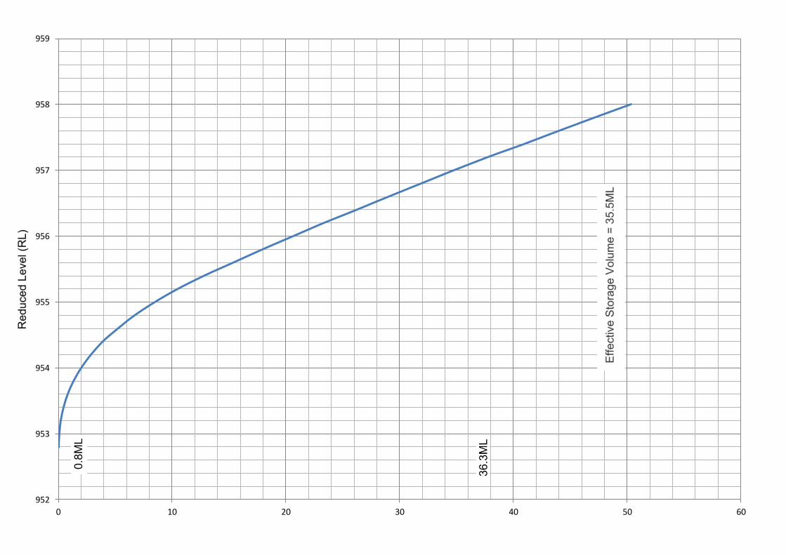
952
953
954
955
956
957
958
959
0 10 20 30 40 50 60

957
958
959
960
961
962
963
964
965
0 2 4 6 8 10 12 14 16 18 20

955.5
956.0
956.5
957.0
957.5
958.0
958.5
959.0
959.5
960.0
0 1 2 3 4 5 6 7 8 9 10

AECOM
Armidale Regional Landfill – Landfill Cell 1 Detailed Design Report
\\ausyd1fp001\Projects\600X\60011672\Delivery Phase post 2012\5. Draft docs\6.1 Reports\Design Report\Design Report FINAL 28-09-15.docx 28-Sep-2015 Prepared for – Armidale Dumaresq Council – ABN: 63 781 014 253
Appendix D
Drainage Plan

1010.00
1010.00
1005.00
1005
.00
1000.00
1000.00
1000
.00
1000
.00
995.
00
995.
00
995.00
995.00
990.
00
990.
00
990.00
990.00
985.
00
985.00
985.00
980.0
0
980.00
980.00
975.
00
975.
00
975.00
970.0
0
970.
00
970.00
965.00
965.
00
965.00 965.00
960.00
960.
00
960.00
955.
00
955.00
N
CLEAN WATER DRAINOUTLET ROCK APRON
DRY BASIN(SPILL RL 957.1)
SEDIMENTATION BASIN(SPILL RL 958.5)
LEACHATE STORAGE POND(SPILL RL 963.0)
EXISTING WATERSTORAGE DAMTO REMAIN
EXISTING WATERSTORAGE DAM ANDSPILLWAY TO REMAIN
LANDFILL CELL 1
300 ND RCP UNDERFLOWOUTLET PIPELINE (TODISSIPATION BASIN)
LANDFILL PERIMETERACCESS ROAD
CULVERT 1 - Ø600 RCP.REFER CULVERT SECTIONON DRG CI-0351.
EXISTING SPILLWAY TO BEFILLED IN TO RL 965.0 MIN.
CLEAN WATER DRAINOUTLET TO EXISTINGWATERCOURSE
CULVERT 2 - Ø900 RCP.REFER CULVERT SECTIONON DRG CI-0351.
RAISE EXISTING DAMEMBANKMENT TO RL 965.0 MIN.(SPILL RL 964.0)
TYPE
3
TYPE
2
TYPE
2
TYPE
1
TYPE
1TY
PE 2
TYPE
2TY
PE 3
TYPE 3
CLEANWATERDRAIN
LANDFILLACCESS ROAD
CELL 1 PERIMETERDIRTY WATER DRAIN
DIRTY WATER DRAIN TOSEDIMENTATION BASIN
SITE ENTRANCE ROAD(DESIGN BY COUNCIL)
PERIMETER CLEANWATER DRAIN
CLEAN WATER DIVERSION DRAINTO OUTLET INTO EXISTINGCREEK (DESIGN BY OTHERS)
PERIMETER CLEANWATER DRAIN
MD01 CH 0.000
MC01 CH 496.770
MC01 CH 180.000
MD01 CH 340.000
DRAIN HIGH POINT
PERIMETER CLEANWATER DIVERSION DRAIN
NOTES
1. REFER TO DRG CI-0332 FOR DRAINAGE LININGSCHEDULE AND DRG CI-0341 FOR DRAINAGEDETAILS AND DRAIN TYPE.
LEGEND
Last
sav
ed b
y: C
OO
KJ3
(201
5-09
-17)
L
ast P
lotte
d: 2
015-
09-1
7
SHEET TITLE
DRAINAGEPLAN
SHEET NUMBER
60011672-SHT-CI-0301File
nam
e: P
:\600
X\6
0011
672\
5. C
AD
\02-
SH
EE
TS\6
0011
672-
SH
T-C
I-030
1.D
WG
PROJECT NUMBER
60011672
I/R DATE DESCRIPTION
ISSUE/REVISION
A 28.11.2014 PRELIM. DETAILED DESIGN
B NOT ISSUED
C 02.03.2015 DETAILED DESIGN
D 29.06.2015 ISSUED FOR TENDER
E 18.09.2015 ISSUED FOR TENDER
DPSCAK
DESIGNER CHECKED APPROVED
PROJECT MANAGEMENT INITIALS
AK SC DP
This
dra
win
g is
con
fiden
tial a
nd s
hall
only
be
used
for t
he p
urpo
se o
f thi
s pr
ojec
t. Th
e si
gnin
g of
this
title
blo
ck c
onfir
ms
the
desi
gn a
nd d
rafti
ng o
f thi
s pr
ojec
t hav
e be
en p
repa
red
and
chec
ked
in a
ccor
danc
e w
ith th
e A
EC
OM
qua
lity
assu
ranc
e sy
stem
to IS
O 9
001-
2000
.
ISO
A1
594m
m x
841
mm
KEY PLAN
REGISTRATION
CONSULTANT
AECOM Australia Pty LtdA.B.N 20 093 846 925www.aecom.com
CLIENT
PROJECT
Armidale Landfill -Cell 1 Works
NOT FOR CONSTRUCTION
SAFETY IN DESIGN INFORMATION
ARE THERE ANY ADDITIONAL HAZARDS / RISKSNOT NORMALLY ASSOCIATED WITH THE TYPESOF WORK DETAILED ON THIS DRAWING?
NOYES
PROPERTY BOUNDARY
0 50 100
1:2000
m
EXISTING CONTOURS980.00
PERIMETER CLEANWATER DIVERSION DRAINDIRTY WATER DRAIN
SPILLWAY
CULVERT
DRAINAGE PIPELINE
CLEAN WATERDISCHARGE POINT

AECOM
Armidale Regional Landfill – Landfill Cell 1 Detailed Design Report
\\ausyd1fp001\Projects\600X\60011672\Delivery Phase post 2012\5. Draft docs\6.1 Reports\Design Report\Design Report FINAL 28-09-15.docx 28-Sep-2015 Prepared for – Armidale Dumaresq Council – ABN: 63 781 014 253
Appendix E
Drainage Catchment Plan


AECOM
Armidale Regional Landfill – Landfill Cell 1 Detailed Design Report
\\ausyd1fp001\Projects\600X\60011672\Delivery Phase post 2012\5. Draft docs\6.1 Reports\Design Report\Design Report FINAL 28-09-15.docx 28-Sep-2015 Prepared for – Armidale Dumaresq Council – ABN: 63 781 014 253
Appendix F
Drainage Calculations

1 IN 100YR DESIGN STORMNode Catchment A (m2) A (km2) tc (mins) I (mm/hr) C (Runoff
Coefficient) Q (m3/s)
QE1 24610 24610 0.025 11.16 155 0.88 0.93 tc = 0.76(A)^0.38 FF(Y=20) 1.14QE2 E1+ 30352 54962 0.055 15.14 132 0.88 1.77 Q = 0.278 * C * I * A C(Y=20) 0.684QE3 E2 + 20608 75570 0.076 17.09 123 0.88 2.26 C10 0.6 FF(Y=10) 1QE4 E3 + 45509 121079 0.121 20.44 113 0.88 3.33 FF(Y=100) 1.46 FF(Y=1) 0.5QE5 E4 + 108178 229257 0.229 26.05 97 0.88 5.42 C(Y=100) = C10 * FF100 0.876QE6 E5 + 16478 245735 0.246 26.75 95 0.88 5.69 FF(Y=20) 1.14
C(Y=10)= C10*FF20 0.684QW1 10317 10317 0.010 8.02 175 0.88 0.44 NotesQW2 W1 + 10673 20990 0.021 10.50 162 0.88 0.83 Figure 5.1 - Design Runoff for Coefficient Contours - 10 Yr Average Recurrance IntervalQW3 W2+ 18803 39793 0.040 13.39 139 0.88 1.35 Figure 1.2 Frequency Factors (ARR Chapter 4)QW4 W4 91134 0.091 18.35 122 0.88 2.71 Armidale - Area A (above 500m)QW5 W3 + W4 + 698 131625 0.132 21.10 110 0.88 3.53QW6 W5+ 81433 213058 0.213 25.34 96 0.88 4.98 1.133333
QD1 43148 43148 0.043 13.81 142 0.88 1.50QD2 QD1 + 23916 67064 0.067 16.33 128 0.88 2.10
1 IN 20YR DESIGN STORMNode Catchment A (m2) A (km2) tc (mins) I (mm/hr) C (Runoff
Coefficient) Q (m3/s)
QE1 24610 24610 0.025 11.16 100 0.68 0.47QE2 E1+ 30352 54962 0.055 15.14 95 0.68 0.99QE3 E2 + 20608 75570 0.076 17.09 85 0.68 1.22QE4 E3 + 45509 121079 0.121 20.44 83 0.68 1.91QE5 E4 + 108178 229257 0.229 26.05 70 0.68 3.05QE6 E5 + 16478 245735 0.246 26.75 69 0.68 3.22
QW1 10317 10317 0.010 8.02 123 0.68 0.24QW2 W1 + 10673 20990 0.021 10.50 113 0.68 0.45QW3 W2+ 18803 39793 0.040 13.39 102 0.68 0.77QW4 W4 91134 0.091 18.35 80 0.68 1.39QW5 W3 + W4 + 698 131625 0.132 21.10 78 0.68 1.95QW6 W5+ 81433 213058 0.21 25.34 74 0.68 3.00
QD1 43148 43148 0.043 13.81 104 0.68 0.85QD2 QD1 + 23916 67064 0.067 16.33 86 0.68 1.10
ARMIDALE LANDFILL DRAINAGE CALCULATIONS
Formulas/ Coefficients

AECOM
Armidale Regional Landfill – Landfill Cell 1 Detailed Design Report
\\ausyd1fp001\Projects\600X\60011672\Delivery Phase post 2012\5. Draft docs\6.1 Reports\Design Report\Design Report FINAL 28-09-15.docx 28-Sep-2015 Prepared for – Armidale Dumaresq Council – ABN: 63 781 014 253
Appendix G
SID Risk Register

Before MitigationHazard Description Probability Exposure Consequence/Outcome Score Risk Level Mitigation Probability Exposure Consequence/Outcome Score Risk Level
Insufficient access and stockpiling/laydown for construction plant and materials potentially resulting in vehicleaccident
Has Happened 5 Daily 5 Major/Fatality 9 19 Extreme Contractor responsible for vehicle management plan / site procedures / inductions / PPE Unlikely 2 Daily 5 Serious/Serious (LTI) 5 12 Medium
Steep Grades on the site may result in construction equipment overturning on steeper grades Has Happened 5 Daily 5 Major/Fatality 9 19 Extreme Plant and equipment used in a manner to prevent overturning. No work to be carried out by heavy machine ongrades greater than 40 degrees.
Possible 4 Weekly 4 Major/Fatality 8 Low
Slips trips and falls - steeper grades on the site and exposed waste may result in site personel slipping andfalling
Has Happened 5 Daily 5 Significant/Disability 7 17 Extreme If possible site personnel should avoid working in areas with slippery surfaces and exposed waste. Staff towear appropriate PPE (boots with ankle protection).
Possible 4 Daily 5 Significant/Disability 9 Low
Personal injury resulting from excavation/contact with existing services (OH power lines) Has Happened 5 Daily 5 Major/Fatality 9 19 Extreme No known services within the extent of works, with Contractor responsible for confirmation prior toconstruction. Any works within 10m of OH powerlines to be undertaken with a spotter.
Almost Impossible 1 Quarterly 2 Major/Fatality 9 12 Medium
Noise exposure (construction staff ) Almost Certain 6 Daily 5 Moderate/Medical Treatment3 14 High Plant maintenance / procedures / PPE to be implemented by Contractor Possible 4 Daily 5 Minor/First Aid 1 10 Medium
Incident that requires first aid Has Happened 5 Weekly 4 Significant/Disability 7 16 High First aid kit in site office / staff training / procedures to be implemented by Contractor Possible 4 Quarterly 2 Minor/First Aid 1 7 Low
Site visitors and site access Almost Certain 6 Daily 5 Serious/Serious (LTI) 5 16 High Site inductions / escort / sign in and out sheet Possible 4 Weekly 4 Minor/First Aid 1 9 Low
Exposure to leachate / contaminated runoff water during landfill operations Heard Of 3 Quarterly 2 Serious/Serious (LTI) 5 10 Medium Landfill leachate water not likely to be encountered with the progessive construction of interim and finalcapping during landfill operations.
Unlikely 2 Quarterly 2 Serious/Serious (LTI) 5 9 Low
Landfill gas migration from waste through capping layer or passive gas vents with environmental and humanhealth consequences. Ignition of landfill gas due to sparks onsite.
Possible 4 Quarterly 2 Significant/Disability 7 13 High The construction of an appropriate gas passive extraction system will provide a preferential pathway for anygas generated
Unlikely 2 Quarterly 2 Moderate/Medical Treatment 3 7 Low
Passive gas vent not maintained and passive system doesn't vent causing gas accumulation in the operationalcell
Possible 4 Quarterly 6 Significant/Disability 7 17 Extreme Inspection and maintenance of the passive gas vent Unlikely 2 Quarterly 2 Significant/Disability 7 11 Medium
Erosion of cover soils causing a hazard for maintenance of batter slopes Possible 4 Quarterly 3 Serious/Serious (LTI) 5 12 Medium Incorporation of erosion control in the design, and maintenance of these systems as requried Unlikely 2 Quarterly 2 Moderate/Medical Treatment 3 7 Low
Insect or other Fauna bite or sting during inspection, maintenance and monitoring Heard Of 3 Monthly 3 Major/Fatality 9 15 High Slopes to be designed of sufficient gradient to to allow access by maintenance vehicles to allow slashing andclearing of habitat of fauna, e.g snakes, prior to inspection and monitoring activities ocurring.
Unlikely 2 Quarterly 2 Significant/Disability 7 11 Medium
After Mitigation
Armidale Landfill Cell 1 - Construction Phase
Armidale Landfill Cell 1 - Operation and Maintenance Phase

AECOM Water and Leachate Management Plan – Armidale Regional Landfill
26-Feb-2016 Prepared for – Armidale Dumaresq Council – ABN: 63 781 014 253
bAppendix B
Water Management Design Drawings

AECOM Water and Leachate Management Plan – Armidale Regional Landfill
26-Feb-2016 Prepared for – Armidale Dumaresq Council – ABN: 63 781 014 253
B
Appendix B Water Management Design Drawings
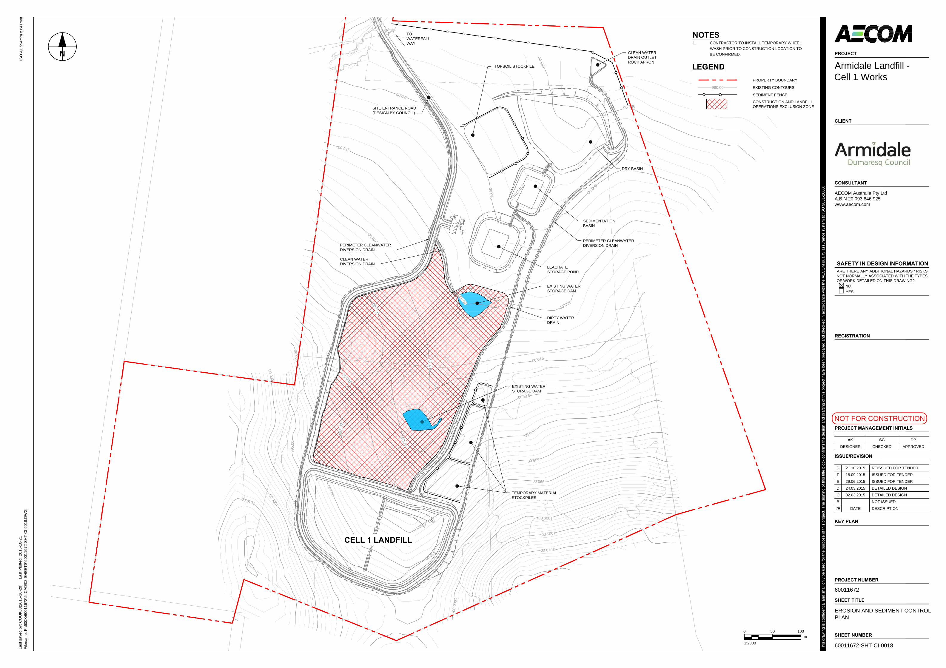
N
1010.00
1010.00
1005.00
1005
.00
1000.00
1000.00
1000
.00
1000
.00
995.
00
995.
00
995.00
995.00
990.
00
990.
00
990.00
990.00
985.
00
985.00
985.00
980.0
0
980.00
980.00
975.
00
975.
00
975.00
970.0
0
970.
00
970.00
965.00
965.
00
965.00 965.00
960.00
960.
00
960.00
955.
00
955.00
TOWATERFALLWAY
CELL 1 LANDFILL
DRY BASIN
SEDIMENTATIONBASIN
LEACHATESTORAGE POND
PERIMETER CLEANWATERDIVERSION DRAIN
EXISTING WATERSTORAGE DAM
DIRTY WATERDRAIN
EXISTING WATERSTORAGE DAM
CLEAN WATERDRAIN OUTLETROCK APRON
PERIMETER CLEANWATERDIVERSION DRAIN
TOPSOIL STOCKPILE
TEMPORARY MATERIALSTOCKPILES
CLEAN WATERDIVERSION DRAIN
SITE ENTRANCE ROAD(DESIGN BY COUNCIL)
NOTES
1. CONTRACTOR TO INSTALL TEMPORARY WHEELWASH PRIOR TO CONSTRUCTION LOCATION TOBE CONFIRMED.
LEGEND
Last
sav
ed b
y: C
OO
KJ3
(201
5-10
-20)
L
ast P
lotte
d: 2
015-
10-2
1
SHEET TITLE
EROSION AND SEDIMENT CONTROLPLAN
SHEET NUMBER
60011672-SHT-CI-0018File
nam
e: P
:\600
X\6
0011
672\
5. C
AD
\02-
SH
EE
TS\6
0011
672-
SH
T-C
I-001
8.D
WG
PROJECT NUMBER
60011672
I/R DATE DESCRIPTION
ISSUE/REVISION
B NOT ISSUED
C 02.03.2015 DETAILED DESIGN
D 24.03.2015 DETAILED DESIGN
E 29.06.2015 ISSUED FOR TENDER
F 18.09.2015 ISSUED FOR TENDER
G 21.10.2015 REISSUED FOR TENDER
DPSCAK
DESIGNER CHECKED APPROVED
PROJECT MANAGEMENT INITIALS
AK SC DP
This
dra
win
g is
con
fiden
tial a
nd s
hall
only
be
used
for t
he p
urpo
se o
f thi
s pr
ojec
t. Th
e si
gnin
g of
this
title
blo
ck c
onfir
ms
the
desi
gn a
nd d
rafti
ng o
f thi
s pr
ojec
t hav
e be
en p
repa
red
and
chec
ked
in a
ccor
danc
e w
ith th
e A
EC
OM
qua
lity
assu
ranc
e sy
stem
to IS
O 9
001-
2000
.
ISO
A1
594m
m x
841
mm
KEY PLAN
REGISTRATION
CONSULTANT
AECOM Australia Pty LtdA.B.N 20 093 846 925www.aecom.com
CLIENT
PROJECT
Armidale Landfill -Cell 1 Works
NOT FOR CONSTRUCTION
SAFETY IN DESIGN INFORMATION
ARE THERE ANY ADDITIONAL HAZARDS / RISKSNOT NORMALLY ASSOCIATED WITH THE TYPESOF WORK DETAILED ON THIS DRAWING?
NOYES
PROPERTY BOUNDARY
0 50 100
1:2000
m
EXISTING CONTOURS980.00
SEDIMENT FENCE
CONSTRUCTION AND LANDFILLOPERATIONS EXCLUSION ZONE

EARTH BANK (LOW FLOW) SD 5-5
CAN BE CONSTRUCTED WITHOR WITHOUT CHANNEL.
ALL BATTER GRADES2(H):1(V) MAX.
GRADIENT OFDRAIN 1% TO 5%
150 mm min.
DIRECTIONOF FLOW
NOTE: ONLY TO BE USED AS TEMPORARY BANKWHERE MAXIMUM UPSLOPE LENGTH IS 80 METRES.
6. COMPLETE PERMANENT OR TEMPORARY STABILISATION WITHIN 10 DAYS OFCONSTRUCTION.
4. BUILD THE DRAINS WITH CIRCULAR, PARABOLIC OR TRAPEZOIDAL CROSSSECTIONS, NOT V SHAPED.
3. ENSURE THE STRUCTURES ARE FREE OF PROJECTIONS OR OTHER IRREGULARITIESTHAT COULD IMPEDE WATER FLOW.
300 mm min.
2 METRES MIN.
2. AVOID REMOVING TREES AND SHRUBS IF POSSIBLE - WORK AROUND THEM.1. BUILD WITH GRADIENTS BETWEEN 1 PERCENT AND 5 PERCENT.
CONSTRUCTION NOTES
5. ENSURE THE BANKS ARE PROPERLY COMPACTED TO PREVENT FAILURE.
B.
B.
A.
flow
Flow
Flow
Staple outside edgesat 300 mm centres
Staple blankets at gridof 1 metre centrelines
After seeding and laying erosion control blanket,apply a soil binder inareas of high erosionhazard
Bury the top of the blanket ina trench 300 mm or more indepth and staple at 150 mm centres. Tamp soil over blanket
Centreline section at point "A".
Centreline section at points "B".
Fill the trench with soiland compact
Overlap - bury upper end of lowerblanket as in 'A'. Overlap end oftop blanket 300 mm and staple at 150 mm centres Staples: 8 gauge
(4mm) wire
150 mm to 300 mm
Overlap blankets 150 mmwhere two or more widthsare required and staplealong joins at 300 mmcentres.
Construction Notes
SD 5-7
1. Remove any rocks, clods, sticks or grass from the surface before laying matting2. Ensure that topsoil is at least 75 mm deep.3. Complete fertilising and seeding before laying the matting. 4. Ensure fabric will be continuously in contact with the soil by grading the surface carefully first. 5. Lay the fabric in "shingle-fashion", with the end of each upstream roll overlapping those downstream. Ensure each roll is anchored properly at its upslope end (Standard Drawing 5-7b). 6. Ensure that the full width of flow in the channel is covered by the matting up to the design storm event, usually in the 10-year ARI time of concentration storm event.7. Divert water from the structure until vegetation is stabilised properly.
Direction of flow
Disturbed area
Undisturbed area
SECTION DETAIL
Direction offlow
On soil, 150 mm x 200 mmtrench with compactedbackfill and on rock, set into surface concrete
Self-supportinggeotextile
1.5 m star picketsat max. 2.5 m centres
1.5 m star picketsat max. 2.5 m centres
SEDIMENT FENCE SD 6-8
600 mm min.
500 mm to 600 mm
Flow
(unless stated otherwise on SWMP/ESCP)20 m max.
Min. 1.5 m
Construction Notes
Star pickets at maximum2.5 m spacings
PLAN
1. Construct sediment fences as close as possible to being parallel to the contours of the site, but with small returns as shown in the drawing to limit the catchment area of any one section. The catchment area should be small enough to limit water flow if concentrated at one point to 50 litres per second in the design storm event, usually the 10-year event. 2. Cut a 150-mm deep trench along the upslope line of the fence for the bottom of the fabric to be entrenched.3. Drive 1.5 metre long star pickets into ground at 2.5 metre intervals (max) at the downslope edge of the trench. Ensure any star pickets are fitted with safety caps.4. Fix self-supporting geotextile to the upslope side of the posts ensuring it goes to the base of the trench. Fix the geotextile with wire ties or as recommended by the manufacturer. Only use geotextile specifically produced for sediment fencing. The use of shade cloth for this purpose is not satisfactory. 5. Join sections of fabric at a support post with a 150-mm overlap. 6. Backfill the trench over the base of the fabric and compact it thoroughly over the geotextile.
Spacing of check dams along centrelineand scour protection below each check dam to be specified on SWMP/ESCP
Rock trenched 200 mm into ground
FLOW
Spillway 150 mm min.150 mm min.
Aggregate or recycled concrete.
SD 5-4
Construction Notes
ROCK CHECK DAM
1. Check dams can be built with various materials, including rocks, logs, sandbags and straw bales. The maintenance program should ensure their integrity is retained, especially where constructed with straw bales. In the case of bales, this might require their replacement each two to four months. 2. Trench the check dam 200 mm into the ground across its whole width. Where rock is used, fill the trenches to at least 100 mm above the ground surface to reduce the risk of undercutting. 3. Normally, their maximum height should not exceed 600 mm above the gully floor. The centre should act as a spillway, being at least 150 mm lower than the outer edges.4. Space the dams so the toe of the upstream dam is level with the spillway of the next downstream dam.
EROSION CONTROL MATTING:CONCENTRATED FLOW
Provide yellow safetycaps on all exposed posts
Last
sav
ed b
y: C
OO
KJ3
(201
5-10
-20)
L
ast P
lotte
d: 2
015-
10-2
1
SHEET TITLE
EROSION AND SEDIMENT CONTROLDETAILS
SHEET NUMBER
60011672-SHT-CI-0019File
nam
e: P
:\600
X\6
0011
672\
5. C
AD
\02-
SH
EE
TS\6
0011
672-
SH
T-C
I-001
9.D
WG
PROJECT NUMBER
60011672
I/R DATE DESCRIPTION
ISSUE/REVISION
A NOT ISSUED
B NOT ISSUED
C 02.03.2015 DETAILED DESIGN
D 29.06.2015 ISSUED FOR TENDER
E 18.09.2015 ISSUED FOR TENDER
F 21.10.2015 REISSUED FOR TENDER
DPSCAK
DESIGNER CHECKED APPROVED
PROJECT MANAGEMENT INITIALS
AK SC DP
This
dra
win
g is
con
fiden
tial a
nd s
hall
only
be
used
for t
he p
urpo
se o
f thi
s pr
ojec
t. Th
e si
gnin
g of
this
title
blo
ck c
onfir
ms
the
desi
gn a
nd d
rafti
ng o
f thi
s pr
ojec
t hav
e be
en p
repa
red
and
chec
ked
in a
ccor
danc
e w
ith th
e A
EC
OM
qua
lity
assu
ranc
e sy
stem
to IS
O 9
001-
2000
.
ISO
A1
594m
m x
841
mm
KEY PLAN
REGISTRATION
CONSULTANT
AECOM Australia Pty LtdA.B.N 20 093 846 925www.aecom.com
CLIENT
PROJECT
Armidale Landfill -Cell 1 Works
NOT FOR CONSTRUCTION
SAFETY IN DESIGN INFORMATION
ARE THERE ANY ADDITIONAL HAZARDS / RISKSNOT NORMALLY ASSOCIATED WITH THE TYPESOF WORK DETAILED ON THIS DRAWING?
NOYES

963.
00
963.00
963.00
963.
00
962.
00
962.
00
962.00
961.
00
961.00
959.
00
959.00
958.00
958.
00
960.
00
960.00
LEACHATE STORAGE
POND
SEDIMENTATION
BASIN
CRES
T RL
963
.80
1CI-0131
CARPARK/HARDSTAND
AREA
1% FALL
2CI-0132
PONTOON MOUNTED INTAKEPUMP (OR SIMILAR) (DESIGNBY OTHERS)
75 ND PE LEACHATERETURN MAIN (TOHEADER TANK)
110 ND LEACHATEEXTRACTION PIPELINE(FROM LEACHATE SUMP)
5.0m NOM.TYP.
PUMP CONTROL PANELDESIGN (BY OTHERS)
LOWPOINT
PIPE BELOWGROUND
PIPE ABOVEGROUND
PIPE BELOWGROUND
PIPE ABOVEGROUND
OPEN END DISCHARGEINTO POND
SERVICES CROSSINGSBENEATH DRAIN. PROVIDE 1000MIN. COVER TO PIPE. (TYP)
90° SWEEPINGBEND (TYP)
REFER COMMON SERVICESTRENCH DETAILS ON DWG CI-0212
DIRTY WATER RETURN PIPELINE(TO IRRIGATION TANK)
CLEAN WATERDIVERSION DRAIN
CABLE PIT
CABLE PIT
PUMP AND STANDBYGENERATOR HOUSE(BY OTHERS)
N
WATER TANK(BY OTHERS)
NOTES
1. DESIGN CONTOURS WITHIN LEACHATE POND ARETOP OF CLAY LINER LEVEL.
2. SERVICES SHOWN DIAGRAMATICALLY ONLY FORCLARITY. REFER TO COMMON SERVICES TRENCHDETAILS.
Last
sav
ed b
y: C
OO
KJ3
(201
5-10
-20)
L
ast P
lotte
d: 2
015-
10-2
1
SHEET TITLE
LEACHATE STORAGE PONDLAYOUT PLAN
SHEET NUMBER
60011672-SHT-CI-0022File
nam
e: P
:\600
X\6
0011
672\
5. C
AD
\02-
SH
EE
TS\6
0011
672-
SH
T-C
I-002
2.D
WG
PROJECT NUMBER
60011672
I/R DATE DESCRIPTION
ISSUE/REVISION
A 28.11.2014 PRELIM. DETAILED DESIGN
B NOT ISSUED
C 02.03.2015 DETAILED DESIGN
D 29.06.2015 ISSUED FOR TENDER
E 18.09.2015 ISSUED FOR TENDER
F 21.10.2015 REISSUED FOR TENDER
DPSCAK
DESIGNER CHECKED APPROVED
PROJECT MANAGEMENT INITIALS
AK SC DP
This
dra
win
g is
con
fiden
tial a
nd s
hall
only
be
used
for t
he p
urpo
se o
f thi
s pr
ojec
t. Th
e si
gnin
g of
this
title
blo
ck c
onfir
ms
the
desi
gn a
nd d
rafti
ng o
f thi
s pr
ojec
t hav
e be
en p
repa
red
and
chec
ked
in a
ccor
danc
e w
ith th
e A
EC
OM
qua
lity
assu
ranc
e sy
stem
to IS
O 9
001-
2000
.
ISO
A1
594m
m x
841
mm
KEY PLAN
REGISTRATION
CONSULTANT
AECOM Australia Pty LtdA.B.N 20 093 846 925www.aecom.com
CLIENT
PROJECT
Armidale Landfill -Cell 1 Works
NOT FOR CONSTRUCTION
SAFETY IN DESIGN INFORMATION
ARE THERE ANY ADDITIONAL HAZARDS / RISKSNOT NORMALLY ASSOCIATED WITH THE TYPESOF WORK DETAILED ON THIS DRAWING?
NOYES
0m
6.25 12.5
1:250
LEGEND
EXISTING CONTOURS980.00
DESIGN CONTOURS980.00
PERIMETER CLEANWATER DIVERSION DRAIN
DIRTY WATER DRAIN
ELECTRICAL CONDUIT
COMMUNICATIONS CONDUIT
LEACHATE EXTRACTION MAIN
LEACHATE RETURN MAIN
DIRTY WATER RETURN MAIN
1.8m HIGH FENCE/
VEHICLE ACCESS GATE
CREST OR TOE OF SLOPE

960.
00
959.00
959.
00
959.00
959.
00
958.00
958.
00
957.00
957.
00
957.00
956.00
955.00
N
SEDIMENTATION
BASIN
DRY BASIN
CRES
T RL
959
.50
LEACHATE
STORAGE POND
1% FALL
1CI-0141
2CI-0141
3CI-0142
TOPSOIL STOCKPILE
5m x 5m x 0.3m THK.ROCKFILL LAYER (d50 = 150)
5m x 5m x 0.3mTHK. ROCKFILLLAYER (d50 = 150)
3m WIDE ACCESS RAMP(10H:1V MAX. GRADE)
LOWPOINT
PONTOON MOUNTEDINTAKE PUMP OR SIMILAR(DESIGN BY OTHERS) PIPE BELOWGROUND
PIPE ABOVEGROUND
PUMP CONTROLPANEL (DESIGNBY OTHERS)
90° SWEEPINGBEND
50 ND PE WATERRETURN PIPELINE (TOIRRIGATION TANK)
PERIMETER CLEANWATER DIVERSION DRAIN
CABLE PIT
Last
sav
ed b
y: C
OO
KJ3
(201
5-10
-20)
L
ast P
lotte
d: 2
015-
10-2
1
SHEET TITLE
SEDIMENTATION BASINLAYOUT PLAN
SHEET NUMBER
60011672-SHT-CI-0023File
nam
e: P
:\600
X\6
0011
672\
5. C
AD
\02-
SH
EE
TS\6
0011
672-
SH
T-C
I-002
3.D
WG
PROJECT NUMBER
60011672
I/R DATE DESCRIPTION
ISSUE/REVISION
A 28.11.2014 PRELIM. DETAILED DESIGN
B NOT ISSUED
C 02.03.2015 DETAILED DESIGN
D 29.06.2015 ISSUED FOR TENDER
E 18.09.2015 ISSUED FOR TENDER
F 21.10.2015 REISSUED FOR TENDER
DPSCAK
DESIGNER CHECKED APPROVED
PROJECT MANAGEMENT INITIALS
AK SC DP
This
dra
win
g is
con
fiden
tial a
nd s
hall
only
be
used
for t
he p
urpo
se o
f thi
s pr
ojec
t. Th
e si
gnin
g of
this
title
blo
ck c
onfir
ms
the
desi
gn a
nd d
rafti
ng o
f thi
s pr
ojec
t hav
e be
en p
repa
red
and
chec
ked
in a
ccor
danc
e w
ith th
e A
EC
OM
qua
lity
assu
ranc
e sy
stem
to IS
O 9
001-
2000
.
ISO
A1
594m
m x
841
mm
KEY PLAN
REGISTRATION
CONSULTANT
AECOM Australia Pty LtdA.B.N 20 093 846 925www.aecom.com
CLIENT
PROJECT
Armidale Landfill -Cell 1 Works
NOT FOR CONSTRUCTION
SAFETY IN DESIGN INFORMATION
ARE THERE ANY ADDITIONAL HAZARDS / RISKSNOT NORMALLY ASSOCIATED WITH THE TYPESOF WORK DETAILED ON THIS DRAWING?
NOYES
0m
6.25 12.5
1:250
NOTES
1. DESIGN CONTOURS WITHIN LEACHATE POND ARETOP OF CLAY LINER LEVEL.
2. SERVICES SHOWN DIAGRAMATICALLY ONLY FORCLARITY. REFER TO COMMON SERVICES TRENCHDETAILS.
LEGEND
EXISTING CONTOURS980.00
DESIGN CONTOURS980.00
PERIMETER CLEANWATER DIVERSION DRAINDIRTY WATER DRAIN
ELECTRICAL CONDUIT
COMMUNICATIONS CONDUIT
LEACHATE EXTRACTION MAIN
LEACHATE RETURN MAIN
DIRTY WATER RETURN MAIN
1.8m HIGH FENCE/
CREST OR TOE OF SLOPE

960.
00
960.00
955.
00
955.00
N
CREST RL 958.00
DRY BASIN
SEDIMENTATION
BASIN
959.00
959.
00
959.00
959.
00
958.00
958.
00
958.00
958.00
957.00
957.
00
957.00
957.00
957.00
956.00
956.00
956.00
954.00954.00
954.00
953.00
953.00
952.00
955.00
955.00
955.00
Ø300 RCP UNDERFLOWOUTLET PIPELINE
VALVE PIT
1CI-0151
2CI-0151
3CI-0151
CLEAN WATER DRAINOUTLET ROCK APRON.REFER TYPICAL DETAILS ONDRG CI-0025 AND CI-0155.
INLET HEADWALL
TOPSOIL STOCKPILE
SPILLWAYRL 957.10
4CI-0152
5CI-0152
PERIMETER CLEANWATER DIVERSION DRAIN
PIPE OUTLETINTO DRAIN
BH02
BH04BH04A
BH4A
BH02A
NOTES
1. DESIGN CONTOURS WITHIN DRY BASIN AREFINISHED SURFACE LEVEL.
Last
sav
ed b
y: C
OO
KJ3
(201
5-10
-20)
L
ast P
lotte
d: 2
015-
10-2
1
SHEET TITLE
DRY BASINLAYOUT PLAN
SHEET NUMBER
60011672-SHT-CI-0024File
nam
e: P
:\600
X\6
0011
672\
5. C
AD
\02-
SH
EE
TS\6
0011
672-
SH
T-C
I-002
4.D
WG
PROJECT NUMBER
60011672
I/R DATE DESCRIPTION
ISSUE/REVISION
A 28.11.2014 PRELIM. DETAILED DESIGN
B NOT ISSUED
C 02.03.2015 DETAILED DESIGN
D 29.06.2015 ISSUED FOR TENDER
E 18.09.2015 ISSUED FOR TENDER
F 21.10.2015 REISSUED FOR TENDER
DPSCAK
0 12.5 25
1:500
m
DESIGNER CHECKED APPROVED
PROJECT MANAGEMENT INITIALS
AK SC DP
This
dra
win
g is
con
fiden
tial a
nd s
hall
only
be
used
for t
he p
urpo
se o
f thi
s pr
ojec
t. Th
e si
gnin
g of
this
title
blo
ck c
onfir
ms
the
desi
gn a
nd d
rafti
ng o
f thi
s pr
ojec
t hav
e be
en p
repa
red
and
chec
ked
in a
ccor
danc
e w
ith th
e A
EC
OM
qua
lity
assu
ranc
e sy
stem
to IS
O 9
001-
2000
.
ISO
A1
594m
m x
841
mm
KEY PLAN
REGISTRATION
CONSULTANT
AECOM Australia Pty LtdA.B.N 20 093 846 925www.aecom.com
CLIENT
PROJECT
Armidale Landfill -Cell 1 Works
NOT FOR CONSTRUCTION
SAFETY IN DESIGN INFORMATION
ARE THERE ANY ADDITIONAL HAZARDS / RISKSNOT NORMALLY ASSOCIATED WITH THE TYPESOF WORK DETAILED ON THIS DRAWING?
NOYES
LEGEND
PROPERTY BOUNDARY
EXISTING CONTOURS980.00
DESIGN CONTOURS980.00
PERIMETER CLEANWATER DIVERSION DRAINDIRTY WATER DRAIN
BH02 EXISTING MONITORINGBOREHOLES
CREST OR TOE OF SLOPE

955.00
958.00
958.00
957.00
957.00
956.00
956.00
954.00
954.00
953.00
952.00
955.00
955.00
Ø300 RCP UNDERFLOWOUTLET PIPELINE. REFER TODWG CI-0151 FOR DETAILS
PIPE OUTLETINVERT R.L. 952.80E - 383676.761N - 6619581.275
VALVE PIT
INLET HEADWALL
0% F
ALL
1CI-0155
2CI-0155
DRY BASIN BH02
BH04BH04A
BH4A
BH02A
300 THK ROCKFILLLAYER (d50 = 150)
OUTLET
ROCK APRON
1% M
IN.
FALL
CONCRETELINED DRAIN
PERIMETER CLEAN WATERDIVERSION DRAIN
INLET HEADWALLINVERT R.L. 953.60E - 383665.540N - 6619551.827
5.0m
25.0
m N
OM
.
1.0m
NO
M.
30.0m NOM.
15.0m NOM.
15.0m NOM.
300 THK ROCKFILLLAYER (d50 = 150)
2.0m
EXISTING MONITORING BOREHOLESTO BE PROTECTED DURINGCONSTRUCTION WORKS (TYP.)
20.0
m N
OM
.
2.0m NOM.ROCKFILLOUTLET DRAIN
PROVIDE PROTECTIVEBOLLARDS AROUND PIT(TYP)
PROVIDE PROTECTIVEBOLLARDS AROUND BOREHOLE(TYP)
PIPE OUTLETINTO DRAIN
NOTES
1. DESIGN CONTOURS WITHIN DRY BASIN AREFINISHED SURFACE LEVEL.
Last
sav
ed b
y: C
OO
KJ3
(201
5-10
-20)
L
ast P
lotte
d: 2
015-
10-2
1
SHEET TITLE
CLEAN WATER DRAIN OUTLETROCK APRON LAYOUT PLAN
SHEET NUMBER
60011672-SHT-CI-0025File
nam
e: P
:\600
X\6
0011
672\
5. C
AD
\02-
SH
EE
TS\6
0011
672-
SH
T-C
I-002
5.D
WG
PROJECT NUMBER
60011672
I/R DATE DESCRIPTION
ISSUE/REVISION
A NOT ISSUED
B NOT ISSUED
C 02.03.2015 DETAILED DESIGN
D 29.06.2015 ISSUED FOR TENDER
E 18.09.2015 ISSUED FOR TENDER
F 21.10.2015 REISSUED FOR TENDER
DPSCAK
0 5 10
1:200
m
DESIGNER CHECKED APPROVED
PROJECT MANAGEMENT INITIALS
AK SC DP
This
dra
win
g is
con
fiden
tial a
nd s
hall
only
be
used
for t
he p
urpo
se o
f thi
s pr
ojec
t. Th
e si
gnin
g of
this
title
blo
ck c
onfir
ms
the
desi
gn a
nd d
rafti
ng o
f thi
s pr
ojec
t hav
e be
en p
repa
red
and
chec
ked
in a
ccor
danc
e w
ith th
e A
EC
OM
qua
lity
assu
ranc
e sy
stem
to IS
O 9
001-
2000
.
ISO
A1
594m
m x
841
mm
KEY PLAN
REGISTRATION
CONSULTANT
AECOM Australia Pty LtdA.B.N 20 093 846 925www.aecom.com
CLIENT
PROJECT
Armidale Landfill -Cell 1 Works
NOT FOR CONSTRUCTION
SAFETY IN DESIGN INFORMATION
ARE THERE ANY ADDITIONAL HAZARDS / RISKSNOT NORMALLY ASSOCIATED WITH THE TYPESOF WORK DETAILED ON THIS DRAWING?
NOYES
LEGEND
EXISTING CONTOURS980.00
DESIGN CONTOURS980.00
PERIMETER CLEANWATER DIVERSION DRAINDIRTY WATER DRAIN
PROPERTY BOUNDARY
EXISTING MONITORINGBOREHOLES
BH02
N
CREST OR TOE OF SLOPE

CREST RL 963.80CREST RL 963.80
SPILL RL 963.00SPILL RL 963.00
EMBANKMENT FILL
3000
900
150
TOP
SO
IL S
TRIP
31
EXISTING GROUNDSURFACE
100 MIN. TOPSOIL LAYERAND HYDROSEED
RE
FER
TY
PIC
AL
LEA
CH
ATE
PO
ND
LIN
ER
SE
CTI
ON
REFER LEACHATEPOND LINER ANCHORTRENCH DETAIL
31
1% FALL
LEA
CH
ATE
STO
RA
GE
ZO
NE
(12.
9ML
CA
PA
CIT
Y)
RL 963.00SPILL LEVELMAXIMUM OPERATING LEVELEMBANKMENT FILL
900
31
3000
150
TOP
SO
IL S
TRIP
31
100 MIN. TOPSOILLAYER ANDHYDROSEED
EXISTING GROUNDSURFACE
REFER LEACHATEPOND LINER ANCHORTRENCH DETAIL
1 SECTION - LEACHATE STORAGE POND
CI-0022 SCALE 1:100
RL 962.60
400
FRE
EB
OA
RD
CO
NTR
OL
LIN
EM
B01
CO
NTR
OL
LIN
EM
B01
2.0mm HDPE LINER(SMOOTH UP/DOWN)
CLAY FILL LINER
PREPARED SUBGRADE(EMBANKMENT FILL OREXISTING GROUND)
900
TYPICAL LEACHATE POND LINER
DETAIL
SCALE 1:20
600
10002000
13
3000
900
13
REF
ER T
YPIC
ALLE
ACH
ATE
PON
DLI
NER
SEC
TIO
N
300
LEACHATE POND LINER
ANCHOR TRENCH DETAIL
SCALE 1:50
EMBANKMENT FILL
CREST RL 963.80
SPILL RL 963.00
ANCHOR TRENCH FILL
Last
sav
ed b
y: C
OO
KJ3
(201
5-10
-20)
L
ast P
lotte
d: 2
015-
10-2
1
SHEET TITLE
LEACHATE STORAGE PONDTYPICAL DETAILSSHEET 1
SHEET NUMBER
60011672-SHT-CI-0131File
nam
e: P
:\600
X\6
0011
672\
5. C
AD
\02-
SH
EE
TS\6
0011
672-
SH
T-C
I-013
1.D
WG
PROJECT NUMBER
60011672
I/R DATE DESCRIPTION
ISSUE/REVISION
A 28.11.2014 PRELIM. DETAILED DESIGN
B NOT ISSUED
C 02.03.2015 DETAILED DESIGN
D 29.06.2015 ISSUED FOR TENDER
E 18.09.2015 ISSUED FOR TENDER
F 21.10.2015 REISSUED FOR TENDER
DPSCAK
DESIGNER CHECKED APPROVED
PROJECT MANAGEMENT INITIALS
AK SC DP
This
dra
win
g is
con
fiden
tial a
nd s
hall
only
be
used
for t
he p
urpo
se o
f thi
s pr
ojec
t. Th
e si
gnin
g of
this
title
blo
ck c
onfir
ms
the
desi
gn a
nd d
rafti
ng o
f thi
s pr
ojec
t hav
e be
en p
repa
red
and
chec
ked
in a
ccor
danc
e w
ith th
e A
EC
OM
qua
lity
assu
ranc
e sy
stem
to IS
O 9
001-
2000
.
ISO
A1
594m
m x
841
mm
KEY PLAN
REGISTRATION
CONSULTANT
AECOM Australia Pty LtdA.B.N 20 093 846 925www.aecom.com
CLIENT
PROJECT
Armidale Landfill -Cell 1 Works
NOT FOR CONSTRUCTION
SAFETY IN DESIGN INFORMATION
ARE THERE ANY ADDITIONAL HAZARDS / RISKSNOT NORMALLY ASSOCIATED WITH THE TYPESOF WORK DETAILED ON THIS DRAWING?
NOYES
0 2500 5000
1:100
mm
0 1250 2500
1:50
mm
0 500 1000
1:20
mm

3000
ANCHOR TRENCH
CLAY FILLBATTER SLOPE
13
13
3-
600
300
12
4-
CLAY FILL
EMBANKMENT FILL
HDPE LINER WITHCONCRETE BACKFILL INANCHOR TRENCH WITHINSPILLWAY CHANNEL (TYP)
RE
FER
TY
PIC
AL
LEA
CH
ATE
PO
ND
LIN
ER
DE
TAIL
2 SECTION - LEACHATE STORAGE POND SPILLWAY
CI-0022 SCALE 1:25
CREST RL 963.80
SPILL RL 963.00
120 THK (32MPa) CONCRETEWITH RL718 MESHCENTRALLY PLACED (TYP)
LEACHATE OVERFLOW DRAIN(CONCRETE LINED)
TO SEDIMENTATION BASIN(REFER DIRTY WATER TYPICAL
DETAIL ON DWG CI-0341)
150 TOPSOIL STRIP
CO
NTR
OL
LIN
EM
B01
500
NOTE: SEE ALSO LONGITUDINAL SECTION MD07
3 SECTION
- SCALE 1:20
CLAY FILL
EMBANKMENT FILL
900
C
L
12
12
1000
CREST RL 963.80
SPILL RL 963.00
120 THK (32MPa) CONCRETEWITH RL718 MESH CENTRALLYPLACED (TYP)
4 SECTION
- SCALE 1:20
EMBANKMENT FILL
C
L
12
12
1000
RL VARIES
120 THK (32MPa) CONCRETEWITH RL718 MESH CENTRALLYPLACED (TYP)
TOP OF BATTER
500 500
500 500
ANCHOR TRENCH(BEHIND)
RL VARIES
SETOUT POINT
SETOUT POINT
500
Last
sav
ed b
y: C
OO
KJ3
(201
5-10
-21)
L
ast P
lotte
d: 2
015-
10-2
1
SHEET TITLE
LEACHATE STORAGE PONDTYPICAL DETAILSSHEET 2
SHEET NUMBER
60011672-SHT-CI-0132File
nam
e: P
:\600
X\6
0011
672\
5. C
AD
\02-
SH
EE
TS\6
0011
672-
SH
T-C
I-013
2.D
WG
PROJECT NUMBER
60011672
I/R DATE DESCRIPTION
ISSUE/REVISION
A NOT ISSUED
B NOT ISSUED
C 02.03.2015 DETAILED DESIGN
D 29.06.2015 ISSUED FOR TENDER
E 18.09.2015 ISSUED FOR TENDER
F 21.10.2015 REISSUED FOR TENDER
DPSCAK
DESIGNER CHECKED APPROVED
PROJECT MANAGEMENT INITIALS
AK SC DP
This
dra
win
g is
con
fiden
tial a
nd s
hall
only
be
used
for t
he p
urpo
se o
f thi
s pr
ojec
t. Th
e si
gnin
g of
this
title
blo
ck c
onfir
ms
the
desi
gn a
nd d
rafti
ng o
f thi
s pr
ojec
t hav
e be
en p
repa
red
and
chec
ked
in a
ccor
danc
e w
ith th
e A
EC
OM
qua
lity
assu
ranc
e sy
stem
to IS
O 9
001-
2000
.
ISO
A1
594m
m x
841
mm
KEY PLAN
REGISTRATION
CONSULTANT
AECOM Australia Pty LtdA.B.N 20 093 846 925www.aecom.com
CLIENT
PROJECT
Armidale Landfill -Cell 1 Works
NOT FOR CONSTRUCTION
SAFETY IN DESIGN INFORMATION
ARE THERE ANY ADDITIONAL HAZARDS / RISKSNOT NORMALLY ASSOCIATED WITH THE TYPESOF WORK DETAILED ON THIS DRAWING?
NOYES
0mm
625 1250
1:25
0 500 1000
1:20
mm

3000
EXISTING GROUNDSURFACE
CREST RL 959.50
SPILL RL 958.50
5000
500
3001
2
FILTER GEOTEXTILE LAYER
PROVIDE 300 THK ROCKFILL LAYER(d50 = 150) OR APPROVEDEQUIVALENT, IF REQUIRED. (TO BECONFIRMED BY ENGINEER ONSITE.)
500
3-
120 THK (32MPa) CONCRETEWITH RL718 MESHCENTRALLY PLACED (TYP)
DIRTY WATER DRAIN ( CONCRETE LINED) FROM LEACHATE STORAGE PONDREFER TYPICAL DETAIL
EMBANKMENT FILL
2 SECTION - SEDIMENTATION BASIN INLET CHANNEL
CI-0023 SCALE 1:25
FALL
CO
NTR
OL
LIN
EM
B02
NOTE: SEE ALSO LONGITUDINAL SECTION MD07
3000
1% FALL
CUT OFF KEY DEPTH VARIES (1000 MIN. DEPTH).TO TERMINATE IN COMPETENT RESIDUALSOILS OR WEATHERED ROCK AS DESIGNATEDBY THE ENGINEER ON SITE.
11
11
EMBANKMENT FILL IN CUT-OFFKEY TO CONTAIN THE HIGHESTAVAILABLE PLASTICITY
2500
EMBANKMENT FILL
31
313
1
EXISTING GROUNDSURFACE
EXISTING GROUNDSURFACE
CREST RL 959.50
SPILL RL 958.50RL 958.50 MAXIMUM STORAGE LEVEL
SE
TTLI
NG
ZO
NE
(3.8
ML
CA
PA
CIT
Y)
RL 957.00
SE
DIM
EN
T ZO
NE
(1.6
ML
CA
PA
CIT
Y)
COMPACTED 300 THK ENGINEERED FILLOR RIP, CONDITION AND COMPACTINSITU MATERIAL AS DESIGNATED BYTHE ENGINEER ON SITE
PREPAREDSUBGRADE (TYP.)
100 MIN. TOPSOIL LAYERAND HYDROSEED
1% FALL
CREST RL 959.50
SPILL RL 958.50
3000
150
TOP
SO
ILS
TRIP15
0
1 SECTION - SEDIMENTATION BASIN
CI-0023 SCALE 1:100
NOTE:NO CUT OFF KEY REQUIRED FORBUND HEIGHTS LESS THAN 1000
CO
NTR
OL
LIN
EM
B02
CO
NTR
OL
LIN
EM
B02
3 SECTION
- SCALE 1:20
C
L
12
12
120 THK (32MPa) CONCRETEWITH RL718 MESH CENTRALLYPLACED (TYP)
RL VARIES
500
1000
CO
NTR
OL
LIN
EM
B01
Last
sav
ed b
y: C
OO
KJ3
(201
5-10
-20)
L
ast P
lotte
d: 2
015-
10-2
1
SHEET TITLE
SEDIMENTATION BASINTYPICAL DETAILSSHEET 1
SHEET NUMBER
60011672-SHT-CI-0141File
nam
e: P
:\600
X\6
0011
672\
5. C
AD
\02-
SH
EE
TS\6
0011
672-
SH
T-C
I-014
1.D
WG
PROJECT NUMBER
60011672
I/R DATE DESCRIPTION
ISSUE/REVISION
A 28.11.2014 PRELIM. DETAILED DESIGN
B NOT ISSUED
C 02.03.2015 DETAILED DESIGN
D 29.06.2015 ISSUED FOR TENDER
E 18.09.2015 ISSUED FOR TENDER
F 21.10.2015 REISSUED FOR TENDER
DPSCAK
DESIGNER CHECKED APPROVED
PROJECT MANAGEMENT INITIALS
AK SC DP
This
dra
win
g is
con
fiden
tial a
nd s
hall
only
be
used
for t
he p
urpo
se o
f thi
s pr
ojec
t. Th
e si
gnin
g of
this
title
blo
ck c
onfir
ms
the
desi
gn a
nd d
rafti
ng o
f thi
s pr
ojec
t hav
e be
en p
repa
red
and
chec
ked
in a
ccor
danc
e w
ith th
e A
EC
OM
qua
lity
assu
ranc
e sy
stem
to IS
O 9
001-
2000
.
ISO
A1
594m
m x
841
mm
KEY PLAN
REGISTRATION
CONSULTANT
AECOM Australia Pty LtdA.B.N 20 093 846 925www.aecom.com
CLIENT
PROJECT
Armidale Landfill -Cell 1 Works
NOT FOR CONSTRUCTION
SAFETY IN DESIGN INFORMATION
ARE THERE ANY ADDITIONAL HAZARDS / RISKSNOT NORMALLY ASSOCIATED WITH THE TYPESOF WORK DETAILED ON THIS DRAWING?
NOYES
0 2500 5000
1:100
mm
0mm
625 1250
1:25
0 500 1000
1:20
mm

3000
CREST RL 959.50
1-
2-1
3
11
11
CUT OFF KEY
2500
SPILL RL 958.50
500
APPROX. RL 957.30
EXISTING GROUNDSURFACE 10
00M
IN.
300
500
12
EMBANKMENT FILL
13
3 SECTION - SEDIMENTATION BASIN SPILLWAY
CI-0023 SCALE 1:25
DIRTY WATER DRAIN (CONCRETE LINED)TO DRY BASIN
(REFER TYPICAL DETAIL ON DWG CI-0341)
CO
NTR
OL
LIN
EM
B02
CONCRETECLAY
NOTE: SEE ALSO LONGITUDINAL SECTION MD08
1 SECTION
- SCALE 1:20
EMBANKMENT FILL
C
L
12
12
3000
RL VARIES
120 THK (32MPa) CONCRETEWITH RL718 MESH CENTRALLYPLACED (TYP)
CREST RL 959.50
1000
2 SECTION
- SCALE 1:20
EMBANKMENT FILL
C
L
12
1000
RL VARIES
120 THK (32MPa) CONCRETEWITH RL718 MESH CENTRALLYPLACED (TYP)
RL VARIES
SPILL RL 958.50
5001
2
RL VARIES
SPILL RL 958.50
SETOUT POINT
SETOUT POINT
CO
NTR
OL
LIN
EM
D08
CO
NTR
OL
LIN
EM
D08
Last
sav
ed b
y: C
OO
KJ3
(201
5-10
-20)
L
ast P
lotte
d: 2
015-
10-2
1
SHEET TITLE
SEDIMENTATION BASINTYPICAL DETAILSSHEET 2
SHEET NUMBER
60011672-SHT-CI-0142File
nam
e: P
:\600
X\6
0011
672\
5. C
AD
\02-
SH
EE
TS\6
0011
672-
SH
T-C
I-014
2.D
WG
PROJECT NUMBER
60011672
I/R DATE DESCRIPTION
ISSUE/REVISION
A NOT ISSUED
B NOT ISSUED
C 02.03.2015 DETAILED DESIGN
D 29.06.2015 ISSUED FOR TENDER
E 18.09.2015 ISSUED FOR TENDER
F 21.10.2015 REISSUED FOR TENDER
DPSCAK
DESIGNER CHECKED APPROVED
PROJECT MANAGEMENT INITIALS
AK SC DP
This
dra
win
g is
con
fiden
tial a
nd s
hall
only
be
used
for t
he p
urpo
se o
f thi
s pr
ojec
t. Th
e si
gnin
g of
this
title
blo
ck c
onfir
ms
the
desi
gn a
nd d
rafti
ng o
f thi
s pr
ojec
t hav
e be
en p
repa
red
and
chec
ked
in a
ccor
danc
e w
ith th
e A
EC
OM
qua
lity
assu
ranc
e sy
stem
to IS
O 9
001-
2000
.
ISO
A1
594m
m x
841
mm
KEY PLAN
REGISTRATION
CONSULTANT
AECOM Australia Pty LtdA.B.N 20 093 846 925www.aecom.com
CLIENT
PROJECT
Armidale Landfill -Cell 1 Works
NOT FOR CONSTRUCTION
SAFETY IN DESIGN INFORMATION
ARE THERE ANY ADDITIONAL HAZARDS / RISKSNOT NORMALLY ASSOCIATED WITH THE TYPESOF WORK DETAILED ON THIS DRAWING?
NOYES
0mm
625 1250
1:25
0 500 1000
1:20
mm

CUT OFF KEY DEPTH VARIES (1000 MIN. DEPTH).TO TERMINATE IN COMPETENT RESIDUALSOILS OR WEATHERED ROCK AS DESIGNATEDBY THE ENGINEER ON SITE.
CREST RL 958.00
SPILL RL 957.10RL 957.10 MAXIMUM STORAGE LEVEL
31
31
31
11
11
150
TOP
SO
IL S
TRIP30
0
EXISTING GROUNDSURFACE
RL 953.60MAXIMUM OPERATING LEVEL
EM
ER
GE
NC
Y W
ATE
RS
TOR
AG
E Z
ON
E(3
5.5M
L C
AP
AC
ITY
)O
PE
RA
TIO
N S
TOR
AG
EZO
NE
(0.8
ML
CA
PA
CIT
Y)
EXISTING GROUND SURFACE100 MIN. TOPSOIL LAYERAND HYDROSEED
1% FALL
PREPAREDSUBGRADE (TYP.)
PREPAREDSUBGRADE (TYP.)
COMPACTED 300 THK ENGINEEREDFILL OR RIP, CONDITION ANDCOMPACT INSITU MATERIAL ASDESIGNATED BY THE ENGINEER ONSITE
EMBANKMENT FILL IN CUT-OFFKEY TO CONTAIN CLAY WITHTHE HIGHEST AVAILABLEPLASTICITY
2500
EMBANKMENT FILL
1 SECTION - DRY BASIN
CI-0024 SCALE 1:100
CO
NTR
OL
LIN
EM
B03
3000
5000NOM.
MAXIMUM OPERATING LEVEL
EXISTING GROUND SURFACEAPPROX RL 954.10
PIPE IL 953.60FALL TO DOWNSTREAM
OUTLET VALVE PIT
PREPARED STORAGEFLOOR
APPROX. RL 952.60
PRECAST REINFORCEDCONCRETE HEADWALLTO SUIT
Ø300 RCP. PROVIDE 2.5%NOM. FALL TO VALVE PIT.REFER TYPICAL PIPETRENCH DETAIL.
PIPE SEAPAGE CUT OFFCOLLAR. REFER TYPICALDETAIL ON DRG CI-0152.
2 SECTION - DRY BASIN PIPE OUTLET (UPSTREAM)
CI-0024 SCALE 1:25
31
31
EMBANKMENT FILL
DRY BASINBATTER
2000MIN.
APPROX. RL 953.80
DN300 DICL PIPE(2.5% FALL)
DN300 DICL PIPE(2.5% FALL)
EXISTING GROUNDSURFACE
PIPE IL 952.80*FALL FALL
DN300 DICLCOUPLING (TYP)
FALL
Ø300 RCP. 2.5%NOM. FALL
150 1500x1500SQR (MIN)
150
50 THK BLINDINGCONCRETE
PUDDLE FLANGE CAST INCONCRETE WALL (TYP)
N25 MASS CONCRETE SUPPORT.PROVIDE 10 THK EPDM RUBBER INSERTBETWEEN FLANGE AND CONCRETE.
SOLID COVER (CLASS D)AND FRAME TO SUIT.PROVIDE VALVE OPENINGABOVE SPINDLE LOCATION.
DN300 RESILIENT SEATED GATEVALVE WITH REMOVABLESPINDLE EXTENSION
DN300 THRUSTDISMANTLING JOINT
3 SECTION - DRY BASIN PIPE OUTLET (DOWNSTREAM) AND VALVE PIT
CI-0024 SCALE 1:25
N12-150 CENTRALLYPLACED. COG ENDS300 MIN. AT CORNERS.
N12 AT 50 CTRS.COG ENDS (TYP)
31
DRY BASIN BATTER
1200
MIN
.
*TO BE CONFIRMED ON SITE
STEPIRONS(TYP)
EXISTING GROUNDSURFACE
Ø300 RCP. 1%MIN. FALL
PIPE OUTLETINTO DRAIN
CONCRETE LINED CLEANWATER DRAIN. REFER TYPICALDETAIL ON DRG CI-0341.
Ø100 SUBSOIL PIPE (1% MIN.FALL) TO OUTLET DRAIN
Last
sav
ed b
y: C
OO
KJ3
(201
5-10
-20)
L
ast P
lotte
d: 2
015-
10-2
1
SHEET TITLE
DRY BASINTYPICAL DETAILSSHEET 1
SHEET NUMBER
60011672-SHT-CI-0151File
nam
e: P
:\600
X\6
0011
672\
5. C
AD
\02-
SH
EE
TS\6
0011
672-
SH
T-C
I-015
1.D
WG
PROJECT NUMBER
60011672
I/R DATE DESCRIPTION
ISSUE/REVISION
A 28.11.2014 PRELIM. DETAILED DESIGN
B NOT ISSUED
C 02.03.2015 DETAILED DESIGN
D 29.06.2015 ISSUED FOR TENDER
E 18.09.2015 ISSUED FOR TENDER
F 21.10.2015 REISSUED FOR TENDER
DPSCAK
DESIGNER CHECKED APPROVED
PROJECT MANAGEMENT INITIALS
AK SC DP
This
dra
win
g is
con
fiden
tial a
nd s
hall
only
be
used
for t
he p
urpo
se o
f thi
s pr
ojec
t. Th
e si
gnin
g of
this
title
blo
ck c
onfir
ms
the
desi
gn a
nd d
rafti
ng o
f thi
s pr
ojec
t hav
e be
en p
repa
red
and
chec
ked
in a
ccor
danc
e w
ith th
e A
EC
OM
qua
lity
assu
ranc
e sy
stem
to IS
O 9
001-
2000
.
ISO
A1
594m
m x
841
mm
KEY PLAN
REGISTRATION
CONSULTANT
AECOM Australia Pty LtdA.B.N 20 093 846 925www.aecom.com
CLIENT
PROJECT
Armidale Landfill -Cell 1 Works
NOT FOR CONSTRUCTION
SAFETY IN DESIGN INFORMATION
ARE THERE ANY ADDITIONAL HAZARDS / RISKSNOT NORMALLY ASSOCIATED WITH THE TYPESOF WORK DETAILED ON THIS DRAWING?
NOYES
0 2500 5000
1:100
mm
0mm
625 1250
1:25

C
L
FINISHED SURFACE
COMPACTEDEMBANKMENT FILLOR BACKFILL
COMPACTEDOVERLAY FILL.REFER NOTES.
COMPACTEDBEDDING FILL.REFER NOTES.
200 200
100
300
TRE
NC
H D
EP
TH V
AR
IES
Ø300RCP
HYDROPHILICSTRIP (CENTRAL)ALL AROUND RCP
COMPACTEDOVERLAY FILL
COMPACTEDEMBANKMENT FILL
REINFORCEDCONCRETE COLLAR
COMPACTEDBEDDING FILL
SL81 MESH AND N12TRIMMER BARS CENTRAL
20030
0
Ø300 REINFORCEDCONCRETE PIPE
FLOW
TYPICAL DRY BASIN OUTLET PIPE TRENCH
AND CUT OFF COLLAR DETAIL
SCALE 1:10
1-
1 SECTION - DRY BASIN OUTLET PIPE TRENCH
- SCALE 1:10
300
MIN
.20
0M
IN.
200MIN.
200MIN.
8No. N12 TRIMMER BARS (CENTRAL)(LENGTH VARIES)
Ø300 REINFORCEDCONCRETE PIPE
SIDE OF PIPE TRENCH
MINIMUM EXTENT OFCONCRETE COLLAR
BASE OF PIPE TRENCH
SL81 MESH (CENTRAL)
2-
2 SECTION - REINFORCED CONCRETE CUT OFF COLLAR
- SCALE 1:10
12
12
2500 2500
5000
SETOUT POINT
EXISTING GROUNDSURFACE
1% MIN. FALLTO OUTLET
EMBANKMENT FILL
DRY BASIN EMBANKMENTCREST RL 958.00
SPILLWAY SILL RL 957.10
4 SECTION - DRY BASIN SPILLWAY CHANNEL
CI-0024 SCALE 1:50
GROUND SURFACE
5 SECTION - DRY BASIN SPILLWAY LONGSECTION
CI-0024 SCALE 1:50
3000DRY BASIN EMBANKMENT CREST
UNLINED SPILLWAYCHANNEL
TO DRY BASINSTORAGE 1% NOM. 3.3% NOM.
TO CLEANWATER DRAIN
900
UNLINED SPILLWAYCHANNEL
CO
NTR
OL
LIN
EM
D09
RL 957.10
Last
sav
ed b
y: C
OO
KJ3
(201
5-10
-20)
L
ast P
lotte
d: 2
015-
10-2
1
SHEET TITLE
DRY BASINTYPICAL DETAILSSHEET 2
SHEET NUMBER
60011672-SHT-CI-0152File
nam
e: P
:\600
X\6
0011
672\
5. C
AD
\02-
SH
EE
TS\6
0011
672-
SH
T-C
I-015
2.D
WG
PROJECT NUMBER
60011672
I/R DATE DESCRIPTION
ISSUE/REVISION
A NOT ISSUED
B NOT ISSUED
C 02.03.2015 DETAILED DESIGN
D 29.06.2015 ISSUED FOR TENDER
E 18.09.2015 ISSUED FOR TENDER
F 21.10.2015 REISSUED FOR TENDER
DPSCAK
DESIGNER CHECKED APPROVED
PROJECT MANAGEMENT INITIALS
AK SC DP
This
dra
win
g is
con
fiden
tial a
nd s
hall
only
be
used
for t
he p
urpo
se o
f thi
s pr
ojec
t. Th
e si
gnin
g of
this
title
blo
ck c
onfir
ms
the
desi
gn a
nd d
rafti
ng o
f thi
s pr
ojec
t hav
e be
en p
repa
red
and
chec
ked
in a
ccor
danc
e w
ith th
e A
EC
OM
qua
lity
assu
ranc
e sy
stem
to IS
O 9
001-
2000
.
ISO
A1
594m
m x
841
mm
KEY PLAN
REGISTRATION
CONSULTANT
AECOM Australia Pty LtdA.B.N 20 093 846 925www.aecom.com
CLIENT
PROJECT
Armidale Landfill -Cell 1 Works
NOT FOR CONSTRUCTION
SAFETY IN DESIGN INFORMATION
ARE THERE ANY ADDITIONAL HAZARDS / RISKSNOT NORMALLY ASSOCIATED WITH THE TYPESOF WORK DETAILED ON THIS DRAWING?
NOYES
0 1250 2500
1:50
mm
0 250 500
1:10
mm

110
EXISTING GROUNDSURFACE
SPILL RL 952.00
300 THK ROCKFILL LAYER(d50 = 150) TO FOLLOWEXISTING GROUND SURFACE
25m NOM.
RL 951.450% FALL
SEPARATIONGEOTEXTILE (TYP)
1 SECTION
CI-0025 SCALE 1:25
EXISTING GROUNDSURFACE
WIDTH VARIES(10m MIN, 30m MAX)
2 SECTION
CI-0025 SCALE 1:25
RL VARIES RL VARIES
1000 NOM.
12
12
RL 951.45 0% FALL
12
2
1
300 300
20005000
FLOW
100 MIN. SHOTCRETELAYER WITH RL718 MESHCENTRALLY PLACED
ROCK APRONCLEANWATER DRAIN
REFER TYPICAL DETAIL
FLOW
300 THK ROCKFILLLAYER WITHIN APRON
300 THK ROCKFILLLAYER WITHIN APRON
SEPARATIONGEOTEXTILE (TYP)
CO
NTR
OL
LIN
EM
E01
CO
NTR
OL
LIN
EM
E01
CO
NTR
OL
LIN
EM
E01
CO
NTR
OL
LIN
EM
E01
20m LONG x 2m WIDEROCKFILL (d50 = 150)OUTLET DRAIN
RL 951.75
Last
sav
ed b
y: C
OO
KJ3
(201
5-10
-20)
L
ast P
lotte
d: 2
015-
10-2
1
SHEET TITLE
CLEANWATER DRAINOUTLET ROCK APRON TYPICAL DETAILS
SHEET NUMBER
60011672-SHT-CI-0155File
nam
e: P
:\600
X\6
0011
672\
5. C
AD
\02-
SH
EE
TS\6
0011
672-
SH
T-C
I-015
5.D
WG
PROJECT NUMBER
60011672
I/R DATE DESCRIPTION
ISSUE/REVISION
A NOT ISSUED
B NOT ISSUED
C 02.03.2015 DETAILED DESIGN
D 29.06.2015 ISSUED FOR TENDER
E 18.09.2015 ISSUED FOR TENDER
F 21.10.2015 REISSUED FOR TENDER
DPSCAK
DESIGNER CHECKED APPROVED
PROJECT MANAGEMENT INITIALS
AK SC DP
This
dra
win
g is
con
fiden
tial a
nd s
hall
only
be
used
for t
he p
urpo
se o
f thi
s pr
ojec
t. Th
e si
gnin
g of
this
title
blo
ck c
onfir
ms
the
desi
gn a
nd d
rafti
ng o
f thi
s pr
ojec
t hav
e be
en p
repa
red
and
chec
ked
in a
ccor
danc
e w
ith th
e A
EC
OM
qua
lity
assu
ranc
e sy
stem
to IS
O 9
001-
2000
.
ISO
A1
594m
m x
841
mm
KEY PLAN
REGISTRATION
CONSULTANT
AECOM Australia Pty LtdA.B.N 20 093 846 925www.aecom.com
CLIENT
PROJECT
Armidale Landfill -Cell 1 Works
NOT FOR CONSTRUCTION
SAFETY IN DESIGN INFORMATION
ARE THERE ANY ADDITIONAL HAZARDS / RISKSNOT NORMALLY ASSOCIATED WITH THE TYPESOF WORK DETAILED ON THIS DRAWING?
NOYES
0mm
625 1250
1:25

31
3000
2000 1000
300MIN.
300
600
MIN
.
900
MIN
.
31
PREPAREDSUBGRADE (TYP.)
EXTERNAL PERIMETER BUND
ANCHOR TRENCH DETAIL
SCALE 1:20
SELECT FILL
GEOTEXTILE
REF
ER T
YPIC
AL B
ASE
LIN
ERD
ETAI
L
HDPE LINER
GENERAL FILL TOCONSTRUCT PERIMETERBUND (AS REQUIRED)
TOP OF CLAY LINER LEVEL
5 (NOM)1
FUTURE FINAL LANDFILLCAPPED SURFACE
2100
(NO
M)
CLAY LINER
5 (NOM.)1
FUTURE FINAL LANDFILLCAPPING LAYER (BY OTHERS)
LEACHATE DRAINAGEGRAVEL
FUTURE WASTE(BY OTHERS)
MAXIMUM LIMIT OF WASTEPLACEMENT ON EXTERNAL BUND
LIMIT OF FUTURE FINALWASTE SURFACE
31
3000
2000 1000
300MIN.
600
MIN
.
CLAY LINER
LIMIT OF CELL 1WASTE SURFACE
INTERNAL PERIMETER BUND
AND ANCHOR TRENCH
DETAIL
SCALE 1:20
ANCHORTRENCH FILL
300
FUTURE CELL 2 LEACHATECOLLECTION LAYER
REF
ER T
YPIC
AL B
ASE
LIN
ERD
ETAI
L
PREPAREDSUBGRADE (TYP.)
GEOTEXTILE
HDPE LINER
GENERAL FILL TOCONSTRUCT PERIMETERBUND (AS REQUIRED)
TOP OF CLAY LINER LEVEL
GENERAL FILL
3 (NOM)1
31
FUTURE WASTE(BY OTHERS)
SELECT FILL
1000
ANCHORTRENCH FILL
GENERAL FILL
LEACHATE DRAINAGEGRAVEL
CELL 1FUTURE CELL 2
500
25 THK MARINE PLY BOARD(REMOVE PRIOR TO CELL 2CONSTRUCTION)
MAXIMUM LIMIT OFWASTE PLACEMENT ONINTERNAL BUND
FUTURE INTERIM LANDFILLCAPPING LAYER (BY OTHERS)
500
(NO
M)
Last
sav
ed b
y: C
OO
KJ3
(201
5-10
-20)
L
ast P
lotte
d: 2
015-
10-2
1
SHEET TITLE
LANDFILL BASE LINERTYPICAL DETAILSSHEET 1
SHEET NUMBER
60011672-SHT-CI-0161File
nam
e: P
:\600
X\6
0011
672\
5. C
AD
\02-
SH
EE
TS\6
0011
672-
SH
T-C
I-016
1.D
WG
PROJECT NUMBER
60011672
I/R DATE DESCRIPTION
ISSUE/REVISION
A 28.11.2014 PRELIM. DETAILED DESIGN
B NOT ISSUED
C 02.03.2015 DETAILED DESIGN
D 29.06.2015 ISSUED FOR TENDER
E 18.09.2015 ISSUED FOR TENDER
F 21.10.2015 REISSUED FOR TENDER
DPSCAK
DESIGNER CHECKED APPROVED
PROJECT MANAGEMENT INITIALS
AK SC DP
This
dra
win
g is
con
fiden
tial a
nd s
hall
only
be
used
for t
he p
urpo
se o
f thi
s pr
ojec
t. Th
e si
gnin
g of
this
title
blo
ck c
onfir
ms
the
desi
gn a
nd d
rafti
ng o
f thi
s pr
ojec
t hav
e be
en p
repa
red
and
chec
ked
in a
ccor
danc
e w
ith th
e A
EC
OM
qua
lity
assu
ranc
e sy
stem
to IS
O 9
001-
2000
.
ISO
A1
594m
m x
841
mm
KEY PLAN
REGISTRATION
CONSULTANT
AECOM Australia Pty LtdA.B.N 20 093 846 925www.aecom.com
CLIENT
PROJECT
Armidale Landfill -Cell 1 Works
NOT FOR CONSTRUCTION
SAFETY IN DESIGN INFORMATION
ARE THERE ANY ADDITIONAL HAZARDS / RISKSNOT NORMALLY ASSOCIATED WITH THE TYPESOF WORK DETAILED ON THIS DRAWING?
NOYES
0 500 1000
1:20
mm

SEPARATION GEOTEXTILE
LEACHATE DRAINAGE GRAVEL
PROTECTION GEOTEXTILE
2.0mm HDPE LINER(TEXTURED OR SMOOTHBOTH SIDES)
CLAY LINER
PREPARED SUBGRADE
300
900
TYPICAL BASE LINER DETAIL
SCALE 1:10
TEMPORARY BALLASTLOADING AS SPECIFIED(SAND FILLED BAGS ORAPPROVED EQUIVALENT)
SETOUT LEVEL - TOP OF CLAY LINERREFER DRG CI-0021 FOR DESIGN LEVELS
TOP OF EXCAVATION / FILL LEVEL
Last
sav
ed b
y: C
OO
KJ3
(201
5-10
-20)
L
ast P
lotte
d: 2
015-
10-2
1
SHEET TITLE
LANDFILL BASE LINERTYPICAL DETAILSSHEET 2
SHEET NUMBER
60011672-SHT-CI-0162File
nam
e: P
:\600
X\6
0011
672\
5. C
AD
\02-
SH
EE
TS\6
0011
672-
SH
T-C
I-016
2.D
WG
PROJECT NUMBER
60011672
I/R DATE DESCRIPTION
ISSUE/REVISION
A
E 18.09.2015 ISSUED FOR TENDER
F 21.10.2015 REISSUED FOR TENDER
DPSCAK
DESIGNER CHECKED APPROVED
PROJECT MANAGEMENT INITIALS
AK SC DP
This
dra
win
g is
con
fiden
tial a
nd s
hall
only
be
used
for t
he p
urpo
se o
f thi
s pr
ojec
t. Th
e si
gnin
g of
this
title
blo
ck c
onfir
ms
the
desi
gn a
nd d
rafti
ng o
f thi
s pr
ojec
t hav
e be
en p
repa
red
and
chec
ked
in a
ccor
danc
e w
ith th
e A
EC
OM
qua
lity
assu
ranc
e sy
stem
to IS
O 9
001-
2000
.
ISO
A1
594m
m x
841
mm
KEY PLAN
REGISTRATION
CONSULTANT
AECOM Australia Pty LtdA.B.N 20 093 846 925www.aecom.com
CLIENT
PROJECT
Armidale Landfill -Cell 1 Works
NOT FOR CONSTRUCTION
SAFETY IN DESIGN INFORMATION
ARE THERE ANY ADDITIONAL HAZARDS / RISKSNOT NORMALLY ASSOCIATED WITH THE TYPESOF WORK DETAILED ON THIS DRAWING?
NOYES
0 250 500
1:10
mm

AECOM Water and Leachate Management Plan – Armidale Regional Landfill
26-Feb-2016 Prepared for – Armidale Dumaresq Council – ABN: 63 781 014 253
C
Appendix C
Water Quality Monitoring Plan

AECOM Water and Leachate Management Plan – Armidale Regional Landfill
26-Feb-2016 Prepared for – Armidale Dumaresq Council – ABN: 63 781 014 253
1
Appendix C Water Quality Monitoring and Management Plan

AECOM Water and Leachate Management Plan – Armidale Regional Landfill
26-Feb-2016 Prepared for – Armidale Dumaresq Council – ABN: 63 781 014 253
C


