Installation, Operation and Maintenance Manual D – KIMWC00205-09EN
D - KIMWC00211-09EN - 2/58
IMPORTANT
This Manual is a technical aid and does not represent a binding offer for Daikin. Daikin has drawn up this Manual to the best of its knowledge. The content cannot be held as explicitly or implicitly guaranteed as complete, precise or reliable. All data and specifications contained herein may be modified without notice. The data communicated at the moment of the order shall hold firm. Daikin shall assume no liability whatsoever for any direct or indirect damage, in the widest sense of the term, ensuing from or connected with the use and/or interpretation of this Manual. The entire content is protected by Daikin copyright.
WARNING
Before starting the installation of the unit, please read this manual carefully. Starting up the unit is absolutely forbidden if all instructions contained in this manual are not clear.
Key to symbols
Important note: failure to respect the instruction can damage the unit or compromise operation
Note regarding safety in general or respect of laws and regulations
Note regarding electrical safety
Description of the labels applied to the electrical panel
Single compressor unit
Label Identification
1 – Lifting instructions 6 – Hazardous Voltage warning
2 – Unit nameplate data 7 – Cable tightening warning
3 – Emergency stop 8 – Electrical hazard symbol
4 – Gas type 9 – Water circuit filling warning
5 – Manufacturer’s logo 10 - Non flammable gas symbol
D - KIMWC00211-09EN - 3/58
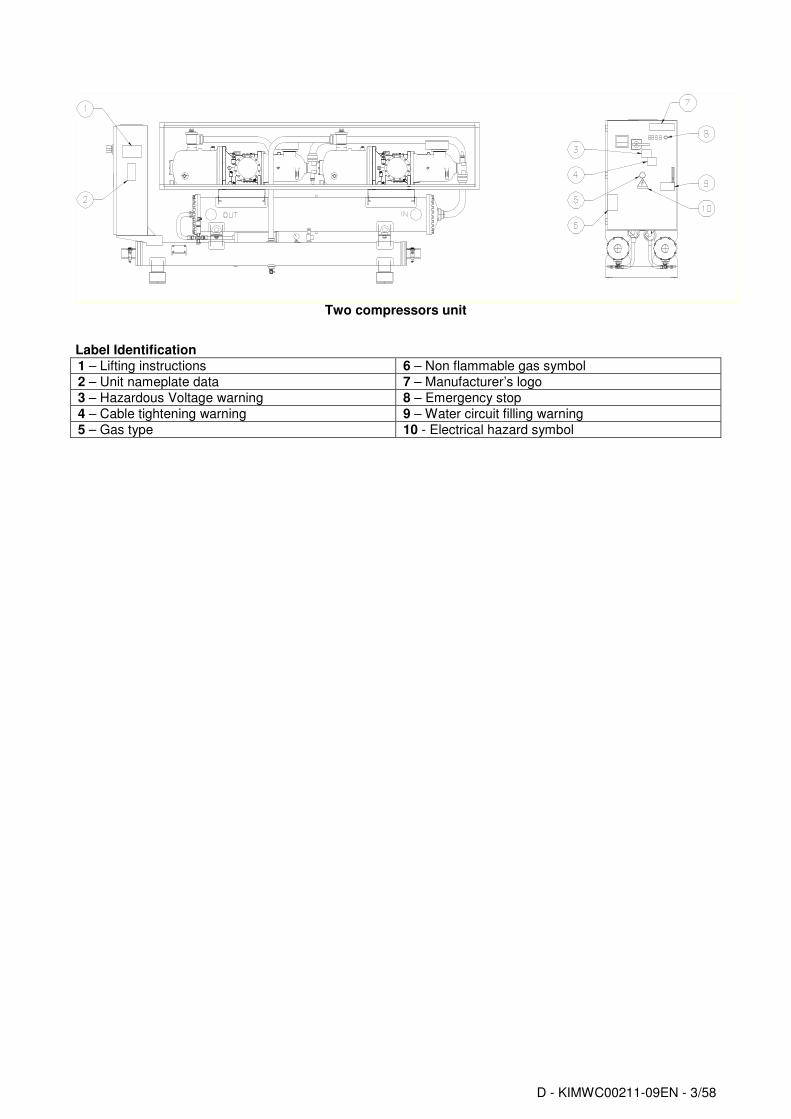
Two compressors unit
Label Identification
1 – Lifting instructions 6 – Non flammable gas symbol
Contents General information .......................................................................................................................................................... 6
Warnings for the operator................................................................................................................................................. 6 Assistance........................................................................................................................................................................ 6 Spare parts....................................................................................................................................................................... 6 Receiving the machine ..................................................................................................................................................... 6 Checks ............................................................................................................................................................................. 6 Purpose of this manual..................................................................................................................................................... 7 Important information on the refrigerant used................................................................................................................... 7 NOMENCLATURE ........................................................................................................................................................... 7 Technical Data EWWD170~600DJYNN........................................................................................................................... 8 Technical Data EWWD190~650DJYNN/A ..................................................................................................................... 10 Technical Data EWLD160~550DJYNN / EWLD160~550DJYNN + OPLR ..................................................................... 12 Sound pressure levels EWWD-DJYNN, EWWD-DJYNN/A............................................................................................ 14 Sound pressure levels EWWD-DJYNN, EWWD-DJYNN/A with sound proof cabinet .................................................... 14 Sound pressure level correction factor EWWD-DJYNN, EWWD-DJYNN/A for different distances ................................ 14 Operating Limits ............................................................................................................................................................. 15
Mechanical Installation................................................................................................................................................... 16 Shipping ......................................................................................................................................................................... 16 Responsibility ................................................................................................................................................................. 16 Safety ............................................................................................................................................................................. 16 Moving and lifting ........................................................................................................................................................... 16 Positioning and assembly............................................................................................................................................... 17 Minimum space requirements ........................................................................................................................................ 18 Ventilation....................................................................................................................................................................... 18 Sound protection ............................................................................................................................................................ 18 Water piping ................................................................................................................................................................... 18 Water treatment.............................................................................................................................................................. 19 Evaporator and exchangers antifreeze protection .......................................................................................................... 20 Installing the flow switch................................................................................................................................................. 20
General specifications .................................................................................................................................................... 28 Electrical components .................................................................................................................................................... 32 Electrical wiring .............................................................................................................................................................. 32 Electrical heaters............................................................................................................................................................ 32 Water pump control ........................................................................................................................................................ 32 Unit On/Off remote control – Electrical wiring................................................................................................................. 32 Double Setpoint – Electrical wiring ................................................................................................................................. 32 External water Setpoint reset – Electrical wiring (Optional)............................................................................................ 32 Unit limitation Electrical wiring (Optional) ...................................................................................................................... 33
Operation ......................................................................................................................................................................... 34 Operator’s responsibilities .............................................................................................................................................. 34 Description of the machine............................................................................................................................................. 34 Description of the refrigeration cycle .............................................................................................................................. 34 Description of the refrigeration cycle with partial heat recovery...................................................................................... 38 Controlling the partial recovery circuit and installation recommendations ...................................................................... 38 Compression process..................................................................................................................................................... 39
Prestartup checks ........................................................................................................................................................... 43 General........................................................................................................................................................................... 43 Units with external water pump ...................................................................................................................................... 44 Electrical power supply................................................................................................................................................... 44 Unbalance in power supply voltage................................................................................................................................ 44 Electrical heaters power supply...................................................................................................................................... 44 Emergency Stop............................................................................................................................................................. 44
Startup procedure ........................................................................................................................................................... 45 Turning on the machine.................................................................................................................................................. 45 Seasonal shutdown ........................................................................................................................................................ 46 Starting up after seasonal shutdown .............................................................................................................................. 46
Routine maintenance ..................................................................................................................................................... 48 Replacement of filter dryer ............................................................................................................................................. 49 Procedure to replace the filter dryer cartridge ................................................................................................................ 49 Replacement of the oil filter ............................................................................................................................................ 50 Refrigerant charge.......................................................................................................................................................... 51 Procedure to replenish refrigerant .................................................................................................................................. 51
Standard Checks............................................................................................................................................................. 52 Temperature and pressure sensors ............................................................................................................................... 52
Test sheet ........................................................................................................................................................................ 53 Water side measurements.............................................................................................................................................. 53 Refrigerant side measurements ..................................................................................................................................... 53 Electrical measurements ................................................................................................................................................ 53
Service and limited warranty.......................................................................................................................................... 54 Obligatory routine checks and starting up apparatuses under pressure .................................................................. 55 Important information regarding the refrigerant used................................................................................................. 56
Table contents Table 1 Acceptable water quality limits....................................................................................................... 19 Table 2 Equivalent Lengths (in meters)....................................................................................................... 26 Table 3 Liquid line sizes................................................................................................................................ 27 Table 4 Discharge line sizes......................................................................................................................... 27 Table 5 Electrical Data EWWD-DJYNN ........................................................................................................ 29 Table 6 Electrical Data EWWD-DJYNN/A..................................................................................................... 30 Table 7 Electrical Data EWLD-DJYNN / EWLD-DJYNN + OPLR ................................................................ 31 Table 8 Typical operating conditions with compressors at 100%............................................................ 45 Table 9 Routine maintenance programme.................................................................................................. 48
Figures contents
Fig. 1 Operating Limits.................................................................................................................................. 15 Fig. 2 - Lifting the unit ................................................................................................................................... 17 Fig. 3 Minimum clearance requirements for machine maintenance ........................................................ 18 Fig. 4 Water piping connections for evaporator......................................................................................... 19 Fig. 5 Water piping connection for heat recovery exchangers................................................................. 19 Fig. 6 Adjusting the safety flow switch ....................................................................................................... 20 Fig. 7 Condenser Located with No Elevation Difference........................................................................... 24 Fig. 8 Condenser Located above Chiller Unit ............................................................................................. 25 Fig. 9 Condenser Located below Chiller Unit ............................................................................................. 25 Fig. 10 User connection to the interface M3 terminal board ..................................................................... 33 Fig. 11 Refrigeration cycle EWWD-DJYNN, EWWD-DJYNN/A................................................................... 35 Fig. 12 Refrigeration cycle EWWD-DJYNN, EWWD-JYNN/A Partial Heat recovery ............................... 36 Fig. 13 Refrigeration cycle EWLD-DJYNN / EWLD-DJYNN + OPLR ......................................................... 37 Fig. 14 Picture of Fr3200 compressor ......................................................................................................... 39 Fig. 15 Compression process ...................................................................................................................... 40 Fig. 16 Refrigeration capacity control mechanism of compressor Fr3200 ............................................. 41 Fig. 17 Capacity control mechanism ........................................................................................................... 42 Fig. 18 - Installation of control devices for Fr 3200 compressor.............................................................. 48
D - KIMWC00211-09EN - 6/58
General information
ATTENTION The units described in the present manual represent a valuable investment. Maximum care should be taken to ensure correct installation and appropriate working conditions of the units. Correct maintenance of the unit is indispensable for its safety and reliability. Manufacturer’s service centres are the only having adequate technical skill for maintenance.
ATTENTION
This manual provides information about the features and procedures for the complete series. All units are delivered from factory as complete sets which include wiring diagrams and dimensional drawings with size, weight and features of each model. WIRING DIAGRAMS AND DIMENSIONAL DRAWINGS MUST BE CONSIDERED ESSENTIAL DOCUMENTS OF
THIS MANUAL In case of any discrepancy between this manual and the two aforesaid documents, please refer to the wiring diagram and dimensional drawings.
IMPORTANT
The present Installation and Maintenance Manual is drawn up for information only and does not constitute an offer
binding upon Daikin.
Specifications are subject to change without prior notice. Refer to the data communicated at the time of the order as per the “Documents Certified” such as “Dimensional Drawings”, “Wiring diagrams” and “Nameplate”. Daikin explicitly rejects any liability for any direct or indirect damage, in the broadest sense, arising from or related to the use and/or interpretation of this Installation and Maintenance Manual.
Safe use and maintenance of the unit, as explained in this Maintenance and Use Manual, is fundamental to prevent any accidents occurring to operators during both operation and maintenance as well as during repair work. Therefore, it is highly recommended that this document be read carefully, complied with and stored safely.
Warnings for the operator
• READ THIS MAINTENANCE AND USE MANUAL BEFORE USING THE UNIT
• THE OPERATOR MUST BE TRAINED AND INSTRUCTED ON HOW TO USE THE UNIT
• THE OPERATOR MUST STRICTLY FOLLOW ALL INSTRUCTIONS, SAFETY REGULATIONS AND LIMITATIONS REGARDING THE USE OF THE UNIT.
Assistance Should additional maintenance be required, it is advisable to consult authorised staff before carrying out any repair work.
Spare parts Spare parts to be used for maintenance of the unit must be original. Therefore, always consult the manufacturer.
Receiving the machine The machine must be inspected for any possible damage immediately upon reaching its final place of installation. All components described in the delivery note must be carefully inspected and checked; any damage must be reported to the carrier. Before connecting the machine to earth, check that the model and power supply voltage shown on the nameplate are correct. Responsibility for any damage after acceptance of the machine cannot be attributed to the manufacturer.
Checks To prevent the possibility of incomplete delivery (missing parts) or transportation damage, please perform the following checks upon receipt of the machine:
D - KIMWC00211-09EN - 7/58
a) Before accepting the machine, please verify every single component in the consignment. Check for any
damage. b) In the event that the machine has been damaged, do not remove the damaged material. A set of photographs
are helpful in ascertaining responsibility. c) Immediately report the extent of the damage to the transportation company and request that they inspect the
machine. d) Immediately report the extent of the damage to the manufacturer representative, so that arrangements can be
made for the required repairs. In no case must the damage be repaired before the machine has been inspected by the representative of the transportation company.
Purpose of this manual The purpose of this manual is to allow the installer and the qualified operator to carry out all required operations in order to ensure proper installation and maintenance of the machine, without any risk to people, animals and/or objects. This manual is an important supporting document for qualified personnel but it is not intended to replace such personnel. All activities must be carried out in compliance with local laws and regulations.
Important information on the refrigerant used This product contains fluorate gases which have a greenhouse effect and which are covered by the Kyoto protocol. Do not release such gases into the atmosphere. Type of refrigerant: R134A GWP value
(1) = 1300
The quantity of refrigerant used is indicated on the identity plate with the name of the unit. Routine inspections may be necessary pursuant to local and/or European laws, to check on possible refrigerant leakage. For more detailed information, contact your local dealer. (1)
GWP=Global warming potential
NOMENCLATURE
EWW D 190 DJ YN N ****
Machine type
ERA : Air cooled condensing unit
EWW : Water-cooled packaged water chiller
EWL : remote condenser water chiller
EWA : Air-cooled chiller, cooling only
EWY : Air-cooled chiller, heatpump
EWC : Air-cooled chiller, cooling only with centrifugal fan
EWT: Air-cooled chiller, cooling only with heat recovery
Hydraulic module (see option code 12)
N : No Hydraulic components
P : pump
B : Buffer tank + pump
Capacity class in KW (Cooling)
Always 3-digit code
Cap < 50 kW : not round : example: 37 kW => 037
50 < Cap < 999 kW : round 0/5 ; 536 kW=> 535
Cap > 999 kW use C-symbol (C=100) example : 2578 kW => C26
Model series
first character : letter A, B,… : major modification
second character : letter A,B,... : minor modification
Refrigerant charge kg 50 50 50 50 100 Refrigerant circuit
N. of circuits 1 1 1 1 2
Piping connections Evaporator water inlet/outlet mm 88.9 88.9 114.3 114.3 114.3
Pipinogconnections Condenser water inlet/outlet inch 5 5 5 5 5
Safety devices High pressure (pressure switch)
Safety devices Low pressure (pressure switch)
Safety devices Emergency stop
Safety devices High discharge temperature on the compressor
Safety devices Phase monitor
Safety devices Low pressure ratio
Safety devices High oil pressure drop
Safety devices Low oil pressure
Notes
(1) At the following nominal conditionsthe: evaporator 12°C/7°C; condenser 30/ 35°C.
(2) Operating and Unit weight are referred to the unit without sound proof cabinet (3) Power and Pressure sound levels are referred to the unit without sound proof cabinet. Pressure
sound levels values with sound proof cabinet table at page 12
Refrigerant charge kg 100 100 100 100 100 Refrigerant circuit
N. of circuits 2 2 2 2 2
Piping connections Evaporator water inlet/outlet mm 114.3 114.3 139.7 139.7 139.7
Pipinogconnections Condenser water inlet/outlet inch 5 5 5 5 5
Safety devices High pressure (pressure switch)
Safety devices Low pressure (pressure switch)
Safety devices Emergency stop
Safety devices High discharge temperature on the compressor
Safety devices Phase monitor
Safety devices Low pressure ratio
Safety devices High oil pressure drop
Safety devices Low oil pressure
Notes
(1) At the following nominal conditionsthe: evaporator 12°C/7°C; condenser 30/ 35°C. (2) Operating and Unit weight are referred to the unit without sound proof cabinet
(3) Power and Pressure sound levels are referred to the unit without sound proof cabinet. Pressure sound levels values with sound proof cabinet table at page12
Refrigerant charge kg 50 50 50 50 100 Refrigerant circuit
N. of circuits 1 1 1 1 1
Piping connections Evaporator water inlet/outlet mm 114.3 114.3 114.3 114.3 139.7
Pipinogconnections Condenser water inlet/outlet inch 5 5 5 5 5
Safety devices High pressure (pressure switch)
Safety devices Low pressure (pressure switch)
Safety devices Emergency stop
Safety devices High discharge temperature on the compressor
Safety devices Phase monitor
Safety devices Low pressure ratio
Safety devices High oil pressure drop
Safety devices Low oil pressure
Notes
(1) At the following nominal conditionsthe: evaporator 12°C/7°C; condenser 30/ 35°C. (2) Operating and Unit weight are referred to the unit without sound proof cabinet
(3) Power and Pressure sound levels are referred to the unit without sound proof cabinet. Pressure sound levels values with sound proof cabinet table at page 12
Refrigerant charge kg 100 100 100 100 100 Refrigerant circuit
N. of circuits 2 2 2 2 2
Piping connections Evaporator water inlet/outlet mm 168.3 168.3 168.3 168.3 168.3
Pipinogconnections Condenser water inlet/outlet inch 5 5 5 5 5
Safety devices High pressure (pressure switch)
Safety devices Low pressure (pressure switch)
Safety devices Emergency stop
Safety devices High discharge temperature on the compressor
Safety devices Phase monitor
Safety devices Low pressure ratio
Safety devices High oil pressure drop
Safety devices Low oil pressure
Notes
(1) At the following nominal conditionsthe: evaporator 12°C/7°C; condenser 30/ 35°C. (2) Operating and Unit weight are referred to the unit without sound proof cabinet
(3) Power and Pressure sound levels are referred to the unit without sound proof cabinet. Pressure sound levels values with sound proof cabinet table at page12
Piping connections Evaporator water inlet/outlet mm 88.9 88.9 88.9 88.9 88.9
Safety devices High pressure (pressure switch)
Safety devices Low pressure (pressure switch)
Safety devices Emergency stop
Safety devices High discharge temperature on the compressor
Safety devices Phase monitor
Safety devices Low pressure ratio
Safety devices High oil pressure drop
Safety devices Low oil pressure
Notes
(1) Nominal cooling capacity and power input are based on: 12/7 °C entering/leaving evaporator water temperature; 45 °C saturated discharge temperature at the compressor
(2) Shipping and unit weight figures are related to the unit without sound proof cabinet
(3) EWLD-DJYNN (+OPLR) version units with 3 l of oil precharged. Oil quantity must be defined by plant designer only
(4) Power and Pressure sound levels are referred to the unit without sound proof cabinet. Pressure sound levels values with sound proof cabinet table at page 12
(5) EWLD-DJYNN (+OPLR) version units are precharged with 5 kg of gas refrigerant. Refrigerant charge must be defined by plant designer only
Piping connections Evaporator water inlet/outlet mm 114.3 114.3 139.7 139.7 139.7
Safety devices High pressure (pressure switch)
Safety devices Low pressure (pressure switch)
Safety devices Emergency stop
Safety devices High discharge temperature on the compressor
Safety devices Phase monitor
Safety devices Low pressure ratio
Safety devices High oil pressure drop
Safety devices Low oil pressure
Notes
(1) Nominal cooling capacity and power input are based on: 12/7 °C entering/leaving evaporator water temperature; 45 °C saturated discharge temperature at the compressor
(2) Shipping and unit weight figures are related to the unit without sound proof cabinet (3) EWLD-DJYNN (+OPLR) version units with 3 l of oil precharged. Oil quantity must be defined by plant
designer only
(4) Power and Pressure sound levels are referred to the unit without sound proof cabinet. Pressure sound levels values with sound proof cabinet table at page 12
(5) EWLD-DJYNN (+OPLR) version units are precharged with 5 kg of gas refrigerant. Refrigerant charge must be defined by plant designer only
D - KIMWC00211-09EN - 14/58
Sound pressure levels EWWD-DJYNN, EWWD-DJYNN/A Sound pressure level at 1 m from the in free field ( rif. 2 x 10
Note: Average sound pressure level rated in accordance to ISO 3744, free field semispheric conditions.
Sound pressure level correction factor EWWD-DJYNN, EWWD-DJYNN/A for different distances
Distance (m) DJYNN DJYNN/A
1 5 10 15 20 25
170 190 0 8.7 13.7 16.9 19.2 21.1
210 230 0 8.7 13.7 16.9 19.2 21.1
260 280 0 8.7 13.7 16.9 19.2 21.1
300 320 0 8.7 13.7 16.9 19.2 21.1
320 380 0 8.7 13.7 16.9 19.2 21.1
380 400 0 8.4 13.4 16.5 18.8 20.6
420 460 0 8.3 13.3 16.4 18.7 20.5
460 500 0 8.3 13.3 16.4 18.7 20.5
500 550 0 8.3 13.3 16.4 18.7 20.5
600 650 0 8.3 13.3 16.4 18.7 20.5
Note: The values are dB(A) (pressure level), in open field conditions on reflecticting surface (directivity factor Q=2)
D - KIMWC00211-09EN - 15/58
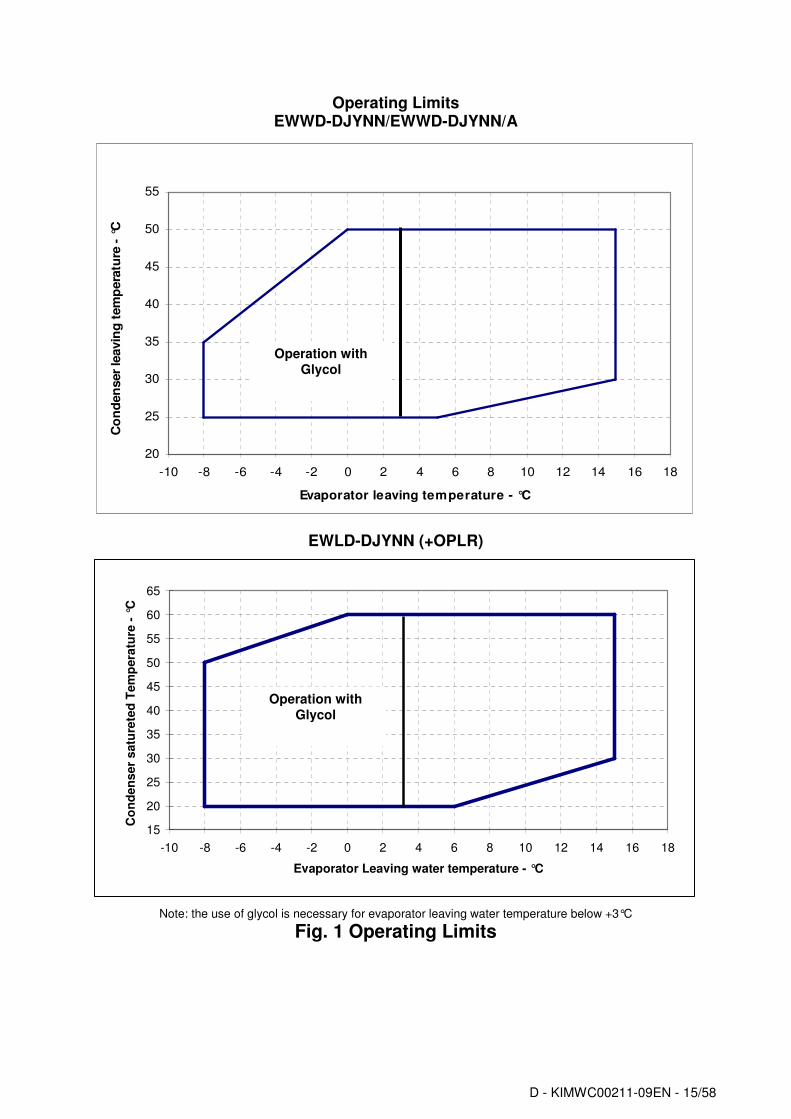
Operating Limits EWWD-DJYNN/EWWD-DJYNN/A
EWLD-DJYNN (+OPLR)
Note: the use of glycol is necessary for evaporator leaving water temperature below +3°C
Fig. 1 Operating Limits
Operating range ECOPLUS
20
25
30
35
40
45
50
55
-10 -8 -6 -4 -2 0 2 4 6 8 10 12 14 16 18
Evaporator leaving temperature - °C
Co
nd
en
ser
leavin
g t
em
pera
ture
- °
C
Operation with Glycol
15
20
25
30
35
40
45
50
55
60
65
-10 -8 -6 -4 -2 0 2 4 6 8 10 12 14 16 18
Evaporator Leaving water temperature - °C
Co
nd
en
se
r s
atu
rete
d T
em
pera
ture
- °
C
Operation with Glycol
D - KIMWC00211-09EN - 16/58
Mechanical Installation
Shipping The stability of the machine during shipping must be ensured. If the machine is shipped with a wooden crossplank on its base, the crossplank must be removed only after the final destination has been reached.
Responsibility The manufacturer declines all responsibility, present and future, for any damage to persons, animals or property caused by negligence of operators failing to follow the installation and maintenance instructions in this manual. All safety equipment must be regularly and periodically checked in accordance with this manual and with local laws and regulations regarding safety and environment protection.
Safety The machine must be firmly secured to the ground. It is essential to observe the following instructions: - The machine can only be lifted using the lifting points on the base of the machine itself. These are the only points that can support the entire weight of the unit. - Do not allow unauthorised and/or unqualified personnel to access the machine. - It is forbidden to access the electrical components without having opened the machine's general disconnecting switch and switched off the power supply. - It is forbidden to access the electrical components without using an insulating platform. Do not access the electrical components if water and/or moisture are present. - All operations on the refrigerant circuit and on components under pressure must be carried out by qualified personnel only. - Replacement of a compressor or addition of lubricating oil must be carried out by qualified personnel only. - Sharp edges can cause wounds. Avoid direct contact. - Avoid introducing solid bodies into the water pipes while the machine is connected to the system. - A mechanical filter must be installed on the water pipe connected to the heat exchanger inlet. - The machine is supplied with safety valves, that are installed on both the high and the low pressure sides of the refrigerant circuit. In case of sudden stop of the unit, follow the instructions on the Control Panel Operating Manual which is part of the on-board documentation delivered to the end user with this manual. It is recommended to perform installation and maintenance with other people. In case of accidental injury or unease, it is necessary to: - keep calm - press the alarm button if present in the installation site - move the injured person in a warm place far from the unit and in rest position - contact immediately emergency rescue personnel of the building or if the Health Emergency Service - wait without leaving the injured person alone until the rescue operators come - give all necessary information to the the rescue operators
WARNING Before carrying out any operation on the machine, please read this instruction and operating manual carefully. Installation and maintenance must be carried out only by qualified personnel that is familiar with the provisions of law and local regulations and has been trained properly or has experience with this type of equipment.
WARNING
Avoid installing the machine in a place that could be dangerous during maintenance operations, such as (but not only) platforms without parapets or railings or areas not complying with the clearance requirements.
Moving and lifting Avoid bumping and/or jolting during unloading from the lorry and moving the machine. Do not push or pull the machine from any part other than the base frame. Secure the machine inside the lorry to prevent it from moving and causing damage to the panels and to the base frame. Do not allow any part of the machine to fall during transportation and/or unloading, as this could cause serious damage. All units of the series are supplied with four lifting points. Only these points may be used for lifting the unit, as shown in figure 2.
D - KIMWC00211-09EN - 17/58
Fig. 2 - Lifting the unit
WARNING Both the lifting ropes and the spacing bar and/or scales must be strong enough to support the machine safely. Please check the unit’s weight on the machine’s nameplate. The weights shown in the "Technical data" tables in the "General Information" chapter refer to standard units. Some specific machines might have accessories that increase their overall weight (heat recovery, etc.)
WARNING The machine must be lifted with the utmost attention and care. Avoid jolting when lifting and lift the machine very slowly, keeping it perfectly level.
Positioning and assembly All units are designed for installation indoors. The machine must be installed on a robust and perfectly level foundation; should the machine be installed on balconies or roofs, it might be necessary to use weight distribution beams. For installation on the ground, prepare a strong cement base that is at least 250 mm wider and longer than the machine. Also, this base must be strong enough to support the weight of the machine as stated in the technical specifications. If the machine is installed in places that are easily accessible to people and animals, it is advisable to install protection gratings for the compressor section. To ensure the best possible performance on the installation site, the following precautions and instructions must be followed:
• Make sure to provide a strong and solid foundation to reduce noise and vibration as much as possible.
• The water in the system must be particularly clean and all traces of oil or rust must be removed. A mechanical water filter must be installed on the machine’s inlet piping.
D - KIMWC00211-09EN - 18/58
Minimum space requirements Every side of the machine must be accessible for all postinstallation maintenance activities. Figure 3 shows the minimum space necessary.
Fig. 3 Minimum clearance requirements for machine maintenance
Ventilation The temperature of the room where the unit is placed should be always maintained between 0°C and 40°C.
Sound protection When sound levels require special control, great care must be exercised to isolate the machine from its base by appropriately applying antivibration elements (supplied as an option). Flexible joints must be installed on the water connections, as well.
Water piping Piping must be designed with the lowest number of elbows and the lowest number of vertical changes of direction. In this way, installation costs are reduced considerably and system performance is improved. The water system should have:
1. Antivibration mountings in order to reduce transmission of vibrations to the underlying structure. 2. Isolating valves to isolate the machine from the water system during service.
3. Manual or automatic air venting device at the system’s highest point; drain device at the system’s lowest point. Neither the evaporator nor the heat recovery device must be positioned at the system’s highest point.
4. A suitable device that can maintain the water system under pressure (expansion tank, etc.) 5. Water temperature and pressure indicators on the machine to assist the operator during service and
maintenance.
6. A filter or device which can remove foreign particles from the water before it enters the pump (in order to prevent cavitation, please consult the pump manufacturer for the recommended type of filter ). The use of a filter prolongs the life of the pump and helps keep the water system in a better condition.
7. Another filter must be installed on the machine inlet water pipe, near the evaporator and heat recovery (if installed). The filter prevents solid particles from entering the heat exchanger, as they could damage it or reduce its heat exchanging capacity.
8. The heat recovery device must be emptied of water during the winter season, unless an ethylenic glycol mixture in appropriate percentage is added to the water circuit.
9. If the machine is intended to replace of another, the entire water system must be emptied and cleaned before the new unit is installed. Regular tests and proper chemical treatment of water are recommended before starting up the new machine.
10. In the event that glycol is added to the water system as antifreeze protection, pay attention to the fact that suction pressure will be lower, the machine’s performance will be lower and water pressure drops will be greater. All machineprotection systems, such as antifreeze, and lowpressure protection will need to be readjusted.
Before insulating water piping, check that there are no leaks.
D - KIMWC00211-09EN - 19/58
Fig. 4 Water piping connections for evaporator
Fig. 5 Water piping connection for heat recovery exchangers
Install a mechanical filter on the inlet to each heat exchanger. Failure to install a mechanical filter allows solid particles and/or welding slag to enter the exchanger. Installation of a filter with a mesh size not exceeding 0.5 mm in diameter is advised. The manufacturer cannot be held responsible for any damage to exchangers ensuing from the lack of a mechanical filter.
Water treatment Before putting the machine into operation, clean the water circuit. Dirt, scaling, corrosion residue and other foreign material can accumulate inside the heat exchanger and reduce its heat exchanging capacity. Pressure drops can increase as well, thus reducing water flow. Proper water treatment therefore reduces the risk of corrosion, erosion, scaling, etc. The most appropriate water treatment must be determined locally, according to the type of system and local characteristics of the process water. The manufacturer is not responsible for damage to or malfunctioning of equipment caused by failure to treat water or by improperly treated water.
Table 1 Acceptable water quality limits PH (25°C) 6.8÷8.0 Total hardness (mg CaCO3 / l) < 200
Electricity conductivity µS/cm (25°C) <800 Iron (mg Fe / l) < 1.0
Evaporator and exchangers antifreeze protection Two or more of below protection methods should be considered when designing the system as a whole:
1. Continuous water flow circulation inside piping and exchangers. 2. Addition of an appropriate amount of glycol inside the water circuit. 3. Additional heat insulation and heating of exposed piping. 4. Emptying and cleaning of the heat exchanger during the winter season.
It is the responsibility of the installer and/or local maintenance personnel to ensure that two or more of the described antifreeze methods are used. Make sure that appropriate antifreeze protection is maintained at all times. Failure to follow the instructions above could result in damage to some of the machine’s components. Damage caused by freezing is not covered by the warranty.
Installing the flow switch To ensure sufficient water flow through the evaporator, it is essential that a flow switch be installed on the water circuit. The flow switch can be installed either on the inlet or outlet water piping. The purpose of the flow switch is to stop the machine in the event of interrupted water flow, thus protecting the evaporator from freezing. A flow switch specifically gauged for this purpose, with identification code 131035072, is available as an option. This paddletype flow switch is suitable for heavyduty outdoor applications (IP67) for pipe diameters in the range of 1" to 6". The flow switch is provided with a clean contact which must be electrically connected to the terminals of the terminal board (check the machine’s wiring diagram for further information). For further information regarding device installation and settings, please read the instruction leaflet in the device box.
Fig. 6 Adjusting the safety flow switch
Refrigerating circuit safety valves
Each system comes with safety valves that are installed on each circuit, both on the evaporator and on the condenser. The purpose of the valves is to release the refrigerant inside the refrigerant circuit in the event of certain malfunctions.
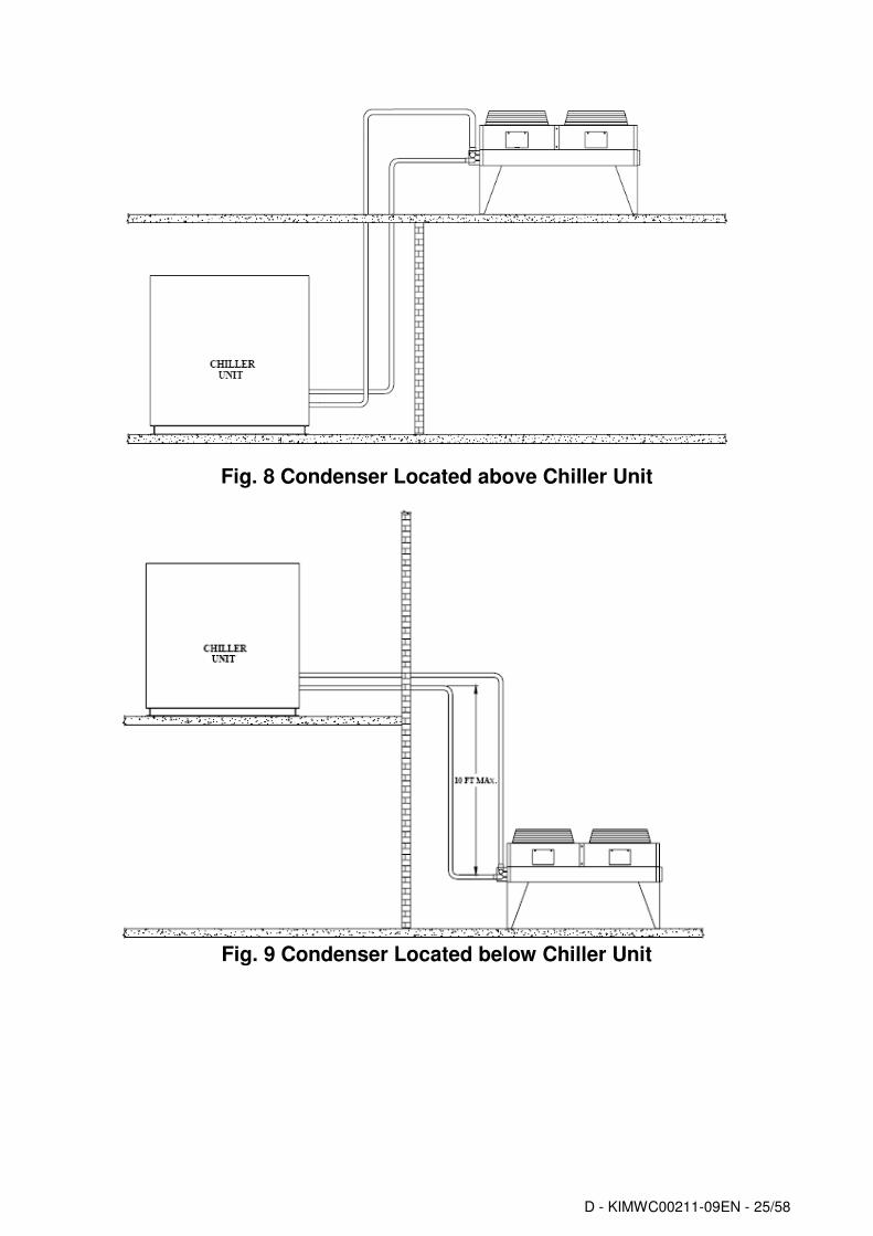
Guidelines for remote condenser application Design of remote condenser application, and, in particular, sizing of piping and piping path, is a responsibility of plant designer. This paragraph is only focused to give suggestion to plant designer, this suggestions have to be weighted with references to application peculiarities. For remote condenser application, such as aircooled or evaporative condensers, the chillers are shipped with holding R134a charge. It is important that the unit be kept tightly closed until the remote condenser is installed and piped to the unit. Chillers are supplied with filter drier, moisture indicator and expansion valve factory mounted as standard. It is the contractor’s responsibility to install the interconnection piping, leak test it and the entire system, evacuate the system and supply the refrigerant charge. All piping must be conformed to the applicable local and state codes. Use refrigerant grade copper tubing only and isolate the refrigeration lines from building structures to prevent transfer of vibration. It is important that the discharge lines be looped at the condenser and trapped at the compressor to prevent refrigerant and oil from draining into the compressors; looping the discharge line also provide greater flexibility. Do not use a saw to remove end caps. This might allow copper chips to contaminate the system. Use a tube cutter or heat to remove caps. When sweating copper joints it is important to flow dry nitrogen through the system prior to charging with refrigerant. This prevents scale formation and the possible formation of an explosive mixture of HFC134a and air. This will also prevent the formation of toxic phosgene gas, which occurs when HFC134a is exposed to open flame. Soft solders are not to be used. For coppertocopper joints use a phoscopper solder with 6% to 8% silver content. A high silver content brazing rod must be used for coppertobrass or coppertosteel joints. Only use oxyacetylene brazing. After the equipment is correctly installed, leak tested and evacuated, it can be charged with R134a refrigerant and started under the supervision of Daikin authorized technician. Charge will be added until the liquid line sight glass is clear, with no bubbles flowing into the expansion valve. Total refrigerant charge will depend on the used remote condenser and volume of refrigerant piping Refrigerant piping design The system can be configured in any of the main arrangements as shown in Figures 7, 8 and 9. The configuration and its associated elevation, along with the total distance between the chiller and the aircooled condenser are important factors in determining the liquid line and discharge line sizes. This will also affect the field refrigerant charges. Consequently, there are physical limits that must not be violated if the system is to operate as designed. 1. The total distance between the chiller and the aircooled condenser should not exceed 60 equivalent meters 2. Liquid line risers must not exceed 5 meters in height from the condenser liquid line connection. 3. Discharge line risers cannot exceed an elevation difference greater than 30 actual meters.
Fig. 7 Condenser Located with No Elevation Difference
D - KIMWC00211-09EN - 25/58
Fig. 8 Condenser Located above Chiller Unit
Fig. 9 Condenser Located below Chiller Unit
D - KIMWC00211-09EN - 26/58
Determining Equivalent Line Length
To determine the appropriate size for field installed liquid and discharge lines, it is first necessary to establish the equivalent length of pipe for each line. The equivalent length is the actual friction loss from the linear run of pipe plus the added friction loss of elbows, valves, etc. Table 2 shows the equivalent length of pipe for various nonferrous valves and fittings. Follow these steps when calculating line size: 1. Start with an initial approximation of equivalent length by assuming that the equivalent length of pipe is 1.5 times the actual pipe length. 2. Refer to Tables 2 and 3 for a first approximation of line size. 3. Check the line size by calculating the actual equivalent length. Note: When calculating the equivalent length, do not include piping of the chiller unit. Only field piping must be considered.
Table 2 Equivalent Lengths (in meters)
Line Size OD (inches) Angle
Valve Short
Radius EL Long
1/4 5.8 0.8 0.6
3/8 7.3 1.2 0.9
1/2 7.3 1.4 1.0
5/8 7.6 1.7 1.2
3/4 7.6 2.0 1.4
7/8 8.5 2.4 1.6
11/8 8.8 0.8 0.6
13/8 10.1 1.0 0.7
15/8 10.4 1.2 0.8
21/8 11.9 1.6 1.0
25/8 13.4 2.0 1.3
31/8 14.3 2.4 1.6
Liquid Line Sizing
In designing liquid lines it is important that the liquid reaches the expansion valve without flash gas, since this gas will reduce the valve capacity. Because flashing gas can be caused by pressure drop in the line, the pressure losses due to friction and changes in static head should be kept at minimum. A check valve must be installed in the liquid line where the ambient temperature can drop below the equipment room temperature to prevent liquid migration to the condenser and to maintain liquid refrigerant in the line for unit startup (if thermostatic expansion valve is used, the check valve also help to keep liquid pressure high enough to keep the valve closed with compressor off). A relief valve should be installed between the check valve and the expansion avlve. The liquid line diameter should be as small as possible while maintaining acceptable pressure drop. This is necessary to minimize refrigerant charge. The total length between the chiller unit and the aircooled condenser must not exceed 60 equivalent meters. Liquid line risers in the system will require an additional 11.5 kPa pressure drop per meter of vertical rise. When it is necessary to have a liquid line riser, make the vertical run immediately after the condenser before any additional restrictions. The liquid line risers must not exceed 3 meters in height from the condenser liquid line connection. The liquid line does not have to be pitched. Liquid lines are not typically insulated. However, if the lines are exposed to solar heat gain or temperatures exceeding 43°C, subcooling may be effected. In these situations, insulate the liquid lines. Reference for liquid line sizing is shown in Table 3. It has to be used for reference only, for circuit working with condensing temperature equal to 55°C and 5°C subcooling at the condenser outlet. Line dimensioning is responsibility of plant designer, use ASHRAE Refrigeration Handbook or other suitable design guide.
D - KIMWC00211-09EN - 27/58
Table 3 Liquid line sizes
Total Equivalent Length (meters) Circuit Capacity
kW 5 10 15 20 25 30 40 50 60
300 11/8 11/8 13/8 13/8 13/8 13/8 13/8 15/8 15/8
350 11/8 13/8 13/8 13/8 13/8 13/8 15/8 15/8 15/8
400 11/8 13/8 13/8 13/8 13/8 15/8 15/8 15/8 15/8
450 11/8 13/8 13/8 13/8 15/8 15/8 15/8 21/8 21/8
Discharge (Hot Gas) Line Sizing
Discharge line size is based on the velocity needed for proper chiller operation handling oil properly and protecting compressor from damage that can result from condensing liquid refrigerant during shutdown. Total friction loss for discharge line from 20 to 40 kPa is considered good design. Carefully consideration must be given for sizing each section of piping so that gas velocities are sufficient at all operating conditions to carry oil. If the velocity in a vertical discharge riser is to low, considerable oil can collect in the riser and horizontal header, causing compressor to lose oil and it can result in compressor damage due to lack of oil. When the compressor load (and the gas velocity in the discharge line) increase the oil collected during reduced load can be carried out in a slug back to the compressor causing damage. Any discharge lines coming into and horizontal header should rise above the centerline of the header. The discharge lines should pitch downward, in the direction of the hot gas flow, at the rate of 6 mm per meter of horizontal run. This is necessary to move by gravity any oil lying in the header. Oil pockets should be avoided because oil would collect at such points and the compressor can become starved. If the chiller unit is below condenser, loop the discharge line to at least 2.5 cm above the top of the condenser. A pressure tap valve should be installed at the condenser to facilitate measuring pressure for service. A relief valve should be installed on the discharge line. Reference for discharge line sizing is shown in Table 4. It has to be used for reference only, for circuit working with evaporator leaving temperature equal to 7°C and condensing temperature equal to 55°C. Line dimensioning is responsibility of plant designer, use ASHRAE Refrigeration Handbook or other suitable design guide..
Table 4 Discharge line sizes
Total Equivalent Length (meters) Circuit Capacity
kW 5 10 15 20 25 30 40 50 60
300 21/8 21/8 21/8 25/8 25/8 25/8 31/8 31/8 31/8
350 21/8 21/8 25/8 25/8 31/8 31/8 31/8 31/8 31/8
400 21/8 25/8 25/8 31/8 31/8 31/8 31/8 2 x 25/8 2 x 25/8
450 25/8 25/8 25/8 31/8 31/8 31/8 2 x 25/8 2 x 25/8 2 x 31/8
Oil Charge
In remote condenser application the oil charge into the compressor has to take into account that a percentage of oil around 1% is usually mixed into the refrigerant, so some oil has to be added to the standard charge if the refrigerant charge exceed the standard charge of the unit. What is important, during the unit operation, is that the oil level in the oil separator is not lower than the ¼ of the upper sideglass.
D - KIMWC00211-09EN - 28/58
Electrical Installation General specifications
CAUTION
All electrical connections to the machine must be carried out in compliance with laws and regulations in force. All installation, operating and maintenance activities must be carried out by qualified personnel. Please refer to the specific wiring diagram for the machine that you have purchased and which was sent with the unit. Should the wiring diagram not appear on the machine or should it have been lost, please contact your dealer who will provide for a copy to be forwarded.
CAUTION
Use copper conductors only. Use of conductors in any material other than copper could cause overheating or corrosion at the connection points and damage the unit. To avoid interference, all control wires must be installed separately from the power cables. Use separate electrical conduits for this purpose.
CAUTION
Concurrence of single-phase and three-phase charges and unbalance between phases can cause leakages towards ground of up to 150 mA during the normal operation of the units of the series. If the unit includes devices that cause superior harmonics (such as VFD and phase cut), the leakage towards ground could increase to very high values (about 2 Ampere). The protections for the power supply system must be designed in accordance with the above mentioned values.
D - KIMWC00211-09EN - 29/58
Table 5 Electrical Data EWWD-DJYNN Unit Compressors Control
(1) Startup current of the biggest compressor + current at 75% of the other compressors at maximum conditions (2) Power factor of compressors under nominal conditions (12/7°C – 30/35°C – 400V) (3) FLA compressors
D - KIMWC00211-09EN - 30/58
Table 6 Electrical Data EWWD-DJYNN/A Unit Compressors Control
(1) Startup current of the biggest compressor + current at 75% of the other compressors at maximum conditions (2) Power factor of compressors under nominal conditions (12/7°C – 30/35°C – 400V) (3) FLA compressors
D - KIMWC00211-09EN - 31/58
Table 7 Electrical Data EWLD-DJYNN / EWLD-DJYNN + OPLR Unit Compressors Control
(1) Startup current of the biggest compressor + current at 75% of the other compressors at maximum conditions (2) Power factor of compressors under nominal conditions (12/7°C – 30/35°C – 400V) (3) FLA compressors
D - KIMWC00211-09EN - 32/58
Electrical components All power and interface electrical connections are specified in the wiring diagram that is shipped with the machine. The installer must supply the following components:
- Power supply wires (dedicated conduit) - Interconnection and interface wires (dedicated conduit) - Thermalmagnetic circuit breaker of suitable size (please see electrical data).
Electrical wiring
Power circuit: Connect the electrical power supply cables to the terminals of the general circuit breaker on the machine’s terminal board. The access panel must have a hole of appropriate diameter for the cable used and its cable gland. A flexible conduit can also be used, containing the three power phases plus earth. In any case, absolute protection against any water penetrating through the connection point must be ensured. Control circuit: Every machine of the series is supplied with an auxiliary 400/115V control circuit transformer. No additional cable for the control system power supply is thus required. Only if the optional separate accumulation tank is requested, the electrical antifreeze resistance must have a separate power supply.
Electrical heaters Each circuit has an electrical heater installed in the compressor, whose purpose is to keep the oil warm thus preventing the presence of liquid refrigerant mixed with the oil in the compressor. Obviously, the operation of the electrical heaters is guaranteed only if there is a constant power supply. If it is not possible to keep the machine powered when inactive during winter, apply at least two of the procedures described in the “Mechanical Installation” section under the “Anti-freeze protection of evaporator and exchangers”. If the plant uses pumps outside the machine (not supplied with the unit), the power line of each pump must be provided with a magnetothermic switch and a control switch.
Water pump control Connect the control contactor coil power supply to terminals 27 and 28 (pump #1) and 401 and 402 (pump 2) located on terminal board M3, and install the contactor on a power supply having the same voltage as the pump contactor coil. The terminals are connected to a clean microprocessor contact. The microprocessor contact has the following commutation capacity: Maximum voltage: 250 Vac Maximum current: 2 A Resistive 2 A Inductive Reference standard: EN 607301 The wiring described above allows the microprocessor to manage the water pump automatically. It is good practice to install a clean status contact pump’s thermalmagnetic circuit breaker and to connect it in series with the flow switch.
Alarm relays – Electrical wiring The machine has a cleancontact digital output that changes state whenever an alarm occurs in one of the refrigerant circuits. Connect this signal to an external visual, sound alarm or to the BMS in order to monitor its operation. See the machine’s wiring diagram for wiring.
Unit On/Off remote control – Electrical wiring The machine has a digital input that allows remote control. A startup timer, a circuit breaker or a BMS can be connected to this input. Once the contact has been closed, the microprocessor launches the startup sequence by first turning on the water pump and then the compressors. When the contact is opened the microprocessor launches the machine shutdown sequence. The contact must be clean.
Double Setpoint – Electrical wiring The Double Setpoint function allows to change over the unit setpoint between two predefined values in the unit controller. An example of an application is ice production during the night and standard operation during the day. Connect a circuit breaker or timer between terminals 5 and 21 of terminal board M3. The contact must be clean.
External water Setpoint reset – Electrical wiring (Optional) The machine’s local setpoint can be modified by means of an external analogue 420 mA signal. Once this function has been enabled, the microprocessor allows to modify the setpoint from the set local value up to a differential of 3°C. 4 mA corresponds to a 0°C differential, 20 mA corresponds to the setpoint plus the maximum differential. The signal cable must be directly connected to terminals 35 and 36 of the M3 terminal board. The signal cable must be of the shielded type and must not be laid in the vicinity of the power cables, so as not to induce interference with the electronic controller.
D - KIMWC00211-09EN - 33/58
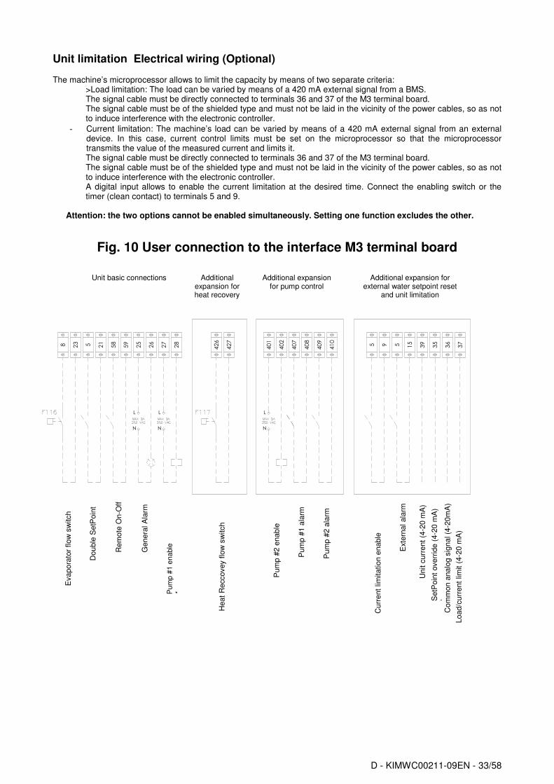
Unit limitation Electrical wiring (Optional)
The machine’s microprocessor allows to limit the capacity by means of two separate criteria: >Load limitation: The load can be varied by means of a 420 mA external signal from a BMS.
The signal cable must be directly connected to terminals 36 and 37 of the M3 terminal board. The signal cable must be of the shielded type and must not be laid in the vicinity of the power cables, so as not to induce interference with the electronic controller.
- Current limitation: The machine’s load can be varied by means of a 420 mA external signal from an external device. In this case, current control limits must be set on the microprocessor so that the microprocessor transmits the value of the measured current and limits it. The signal cable must be directly connected to terminals 36 and 37 of the M3 terminal board. The signal cable must be of the shielded type and must not be laid in the vicinity of the power cables, so as not to induce interference with the electronic controller. A digital input allows to enable the current limitation at the desired time. Connect the enabling switch or the timer (clean contact) to terminals 5 and 9.
Attention: the two options cannot be enabled simultaneously. Setting one function excludes the other.
Fig. 10 User connection to the interface M3 terminal board
Unit basic connections
Additional expansion for pump control
Additional expansion for external water setpoint reset
and unit limitation
Additional expansion for heat recovery
Evapora
tor
flow
sw
itch
Rem
ote
On-O
ff
Genera
l A
larm
Pum
p #
1 e
nable
1
Heat
Reccovey flo
w s
witch
Pum
p #
2 e
nable
Pum
p #
1 a
larm
Pum
p #
2 a
larm
Curr
ent
limitation e
nable
Exte
rnal ala
rm
SetP
oin
t overr
ide (
4-2
0 m
A)
) C
om
mon a
nalo
g s
ignal (4
-20m
A)
Load/c
urr
ent
limit (
4-2
0 m
A)
Unit c
urr
ent
(4-2
0 m
A)
5 5925
26
27
28
35
36
37
39
58
59
15
401
402
407
408
409
410
426
427
8 23
L
N
L
N
L
N
5 21
Double
SetP
oin
t
D - KIMWC00211-09EN - 34/58
Operation Operator’s responsibilities It is important that the operator is appropriately trained and becomes familiar with the system before operating the machine. In addition to reading this manual, the operator must study the microprocessor operating manual and the wiring diagram in order to understand startup sequence, operation, shutdown sequence and operation of all the safety devices. During the machine’s initial startup phase, a technician authorized by the manufacturer is available to answer any questions and to give instructions as to the correct operating procedures. The operator is advised to keep a record of operating data for every installed machine. Another record should also be kept of all the periodical maintenance and servicing activities. If the operator notes abnormal or unusual operating conditions, he is advised to consult the technical service authorized by the manufacturer.
Description of the machine This machine, of the water condensation type, is made up of the following main components:
Compressor: The singlescrew compressor of the Fr 3200 series is of the semihermetic type and utilises gas from the evaporator to cool the motor and allow optimal operation under any expected load conditions. The oilinjection lubrication system does not require an oil pump as oil flow is ensured by the pressure difference between delivery and suction. In addition to ensuring lubrication of ball bearings, oil injection dynamically seals the screw, thus enabling the compression process.
Evaporator: The directexpansion shell and tube type evaporator is of ample size in order to ensure optimum efficiency under all load conditions.
Condenser: The shell and tube type condenser has external high efficiency micro fins (C4). The liquid subcooled by the lower part of the tubes not only improves overall efficiency of
the machine but also compensates variations in heat load by adapting the refrigerant load to all foreseen operating conditions.
Expansion valve: The machine has a an electronic expansion valve, which is controlled by an electronic device called a Driver that optimises its operation.
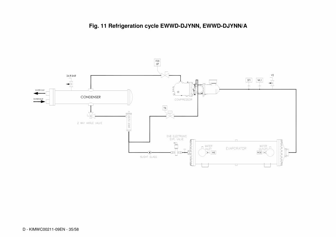
Description of the refrigeration cycle The lowtemperature refrigerant gas from the evaporator is drawn by the compressor through the electric motor, which is cooled by the refrigerant. It is subsequently compressed and during this process the refrigerant mixes with the oil from the oil separator.
The highpressure oilrefrigerant mixture is introduced into the centrifugetype highefficiency oil separator, where the oil is separated from the refrigerant. The oil accumulated on the bottom of the separator is forced by the pressure difference back into the compressor while the oilfree refrigerant is sent to the condenser.
The refrigerant fluid is evenly distributed inside the condenser throughout the volume of the exchanger, and the gas in contact with the tubes is cooled and successively starts to condense.
The condensed fluid at saturation temperature passes through the subcooling section where it looses even more heat, increasing the efficiency of the cycle. The heat taken from the fluid during cooling, condensation and subcooling is exchanged with that of the water passing inside the condenser tubes.
The subcooled fluid flows through the highefficiency filter dryer and then reaches the expansion element (expansion valve) through which a fall in pressure starts off the expansion process resulting in the vaporisation of part of the refrigerant liquid.
The result at this point is a lowpressure and lowtemperature liquidgas mixture entering the evaporator, where it takes the heat required for vaporisation.
When the refrigerant liquidvapour is uniformly distributed in the direct expansion evaporator tubes, heat is exchanged with the cooling water, thus reducing the temperature until complete evaporation, followed by superheating.
Once it has reached the superheatedvapour state, the refrigerant leaves the evaporator and is once again taken into the compressor to repeat the cycle.
Description of the refrigeration cycle with partial heat recovery
The lowtemperature refrigerant gas from the evaporator is drawn by the compressor through the electric motor, which is cooled by the refrigerant. It is subsequently compressed and during this process the refrigerant mixes with the oil from the oil separator.
The highpressure oilrefrigerant mixture is introduced within the highefficiency centrifugaltype oil separator which separates it. The oil depositing on the bottom of the separator through pressure difference is sent back to the compressor while the refrigerant that has been separated from the oil il sent to the partial recovery exchanger, where it dissipates the heat from postoverheating cooling, warming the water which travels through the exchanger. On leaving the exchanger the refrigerant fluid enters the condenser where it is condensed.
The highpressure oilrefrigerant mixture is introduced into the centrifugetype highefficiency oil separator, where the oil is separated from the refrigerant. The oil accumulated on the bottom of the separator is forced by the pressure difference back into the compressor while the oilfree refrigerant is sent to the condenser. The upper part of the condenser has cooling tubes through which about 10% of the heat rejection of the unit is recovered.
These condensers, with partial heat recovery tubes, have crowns with special couplings by which they can be connected to the hot water pipes. When partial recovery is activated, condenser performance is improved since the condenser temperature is lowered further in as much as the surface dedicated to heat discharge is greater.
After passing through the cooling tubes, the gas starts to condense in the central part of the condenser.
The condensed fluid at saturation temperature passes through the subcooling section where it looses even more heat, increasing the efficiency of the cycle. The subcooled fluid flows through the highefficiency filter dryer and then reaches the expansion element (expansion valve) through which a fall in pressure starts off the expansion process resulting in the vaporisation of part of the refrigerant liquid.
The result at this point is a lowpressure and lowtemperature liquidgas mixture entering the evaporator, where it takes the heat required for vaporisation.
When the refrigerant liquidvapour is uniformly distributed in the direct expansion evaporator tubes, heat is exchanged with the cooling water, thus reducing the temperature until complete evaporation, followed by superheating.
Once it has reached the superheatedvapour state, the refrigerant leaves the evaporator and is once again taken into the compressor to repeat the cycle.
Controlling the partial recovery circuit and installation recommendations The partial heat recovery system is not managed and/or controlled by the machine. The installer should follow the suggestions below for best system performance and reliability:
1) Install a mechanical filter on the heat exchanger inlet pipe.
2) Install shutoff valves to isolate the heat exchanger from the water system during periods of inactivity or system maintenance.
3) Install a drain valve that allows the heat exchanger to be emptied in the even that air temperature is expected to fall below 0°C during periods of inactivity of the machine.
4) Install flexible antivibration joints on the heat recovery water inlet and outlet piping, so that transmission of vibrations, and therefore of noise, to the water system is kept as low as possible.
5) Do not load exchanger joints with the weight of the heat recovery piping. The water joints of the exchangers are not designed to support the weight of the piping.
6) Should heat recovery water temperature be lower than ambient temperature, it is advised to switch off the heat recovery water pump 3 minutes after having switched off the last compressor.
Compressor The singlescrew compressor is of the semihermetic type with an asyncronous threephase, twopole motor which is directly splined on the main shaft. The suction gas from the evaporator cools the electric motor before entering the suction ports. There are temperature sensors inside the electric motor which are completely covered by the coil winding and constantly monitor motor temperature. Should the coil winding temperature become very high (120°C), a special external device connected to the sensors and to the electronic controller will deactivate the corresponding compressor. There are only two moving rotating parts and there are no other parts in the compressor with an eccentric and/or alternating movement. The basic components are therefore only the main rotor and the satellites that carry out the compression process, meshing perfectly together. Compression sealing is done thanks to a suitably shaped special composite material that is interposed between the main screw and the satellite. The main shaft on which the main rotor is splined is supported by 2 ball bearings. The system made up in this way is both statically and dynamically balanced before assembly.
D - KIMWC00211-09EN - 39/58
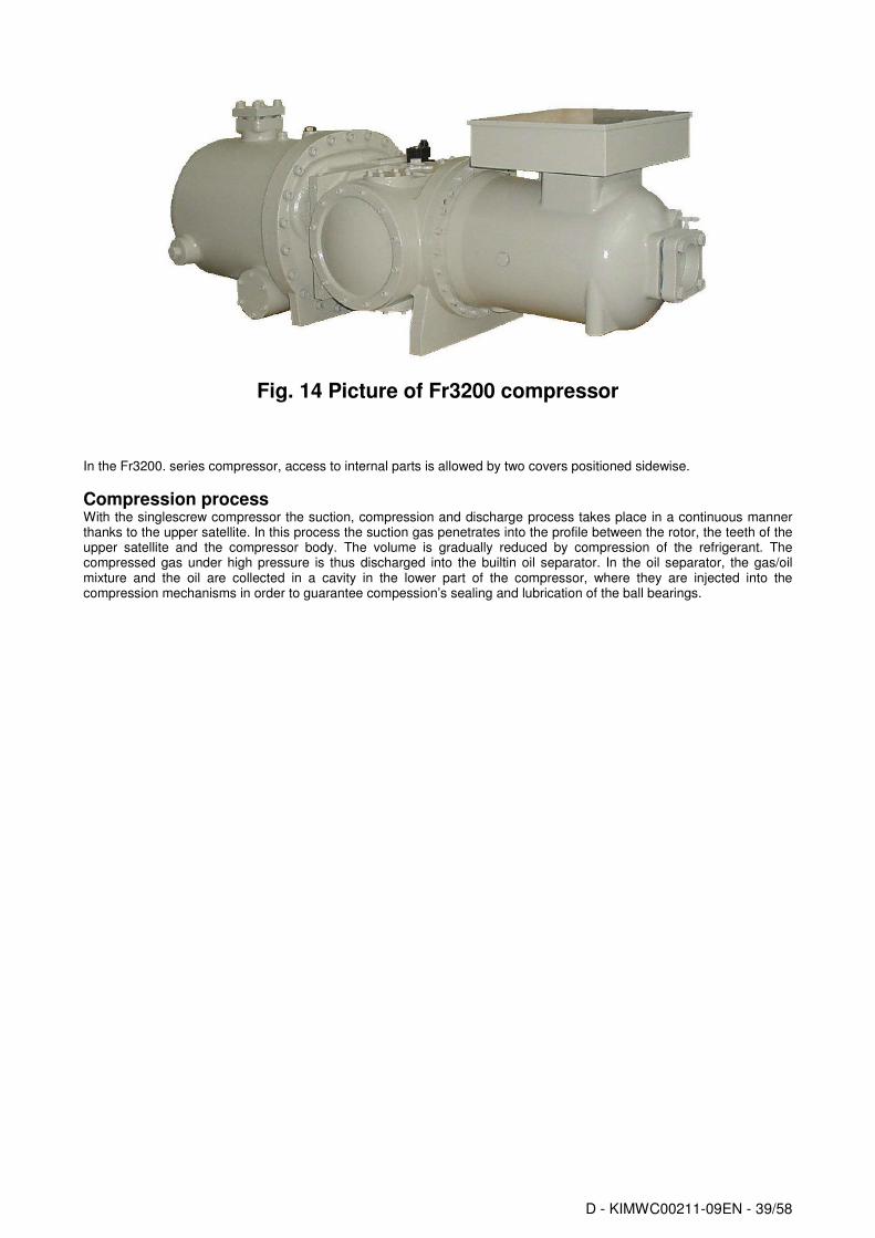
Fig. 14 Picture of Fr3200 compressor
In the Fr3200. series compressor, access to internal parts is allowed by two covers positioned sidewise.
Compression process With the singlescrew compressor the suction, compression and discharge process takes place in a continuous manner thanks to the upper satellite. In this process the suction gas penetrates into the profile between the rotor, the teeth of the upper satellite and the compressor body. The volume is gradually reduced by compression of the refrigerant. The compressed gas under high pressure is thus discharged into the builtin oil separator. In the oil separator, the gas/oil mixture and the oil are collected in a cavity in the lower part of the compressor, where they are injected into the compression mechanisms in order to guarantee compession’s sealing and lubrication of the ball bearings.
D - KIMWC00211-09EN - 40/58
1.
1. E 2. Suction
Main rotor flutes ‘a’, ‘b’ and ‘c’ are in communication at one end with the suction chamber and are sealed at the other end by the upper satellite teeth. As the main rotor turns, the effective length of the flutes increases, thus increasing the volume open to the suction chamber. Figure 1 clearly illustrates this process. As flute ‘a’ assumes the position of flutes ‘b’ and ‘c’ its volume increases, inducing suction vapour to enter the flute.
Upon further rotation of the main rotor, the flutes which have been open to the suction is chamber engage with the satellite teeth. This coincides with each flute being progressively sealed by the main rotor.
Once the flute volume is closed off from the suction chamber, the suction stage of the compression cycle is complete.
2.
3. Compression
As the main rotor turns, the volume of gas trapped within the flute is reduced as the length of the flute shortens and compression occurs.
3.
4. Discharge
As the satellite tooth approaches the end of a flute, the pressure of the trapped vapour reaches a maximum value occurring when the leading edge of the flute begins to overlap the triangular shaped discharge port. Compression immediately ceases as the gas is delivered into the discharge manifold. The satellite tooth continues to scavenge the flute until the flute volume is reduced to zero. This compression process is repeated for each flute/satellite tooth in turn.
4.
Oil separator not shown
Fig. 15 Compression process
c
b
a
c
a b
c
b
a
a
b
Discharge Gas
a
b
Aspirazio
ne
Gas
b
a
c
D - KIMWC00211-09EN - 41/58
FR3200 Compressor
Fig. 16 Refrigeration capacity control mechanism of compressor Fr3200
Load
Oil supply Oil vent
Slide
Spring
Permanent vent to suction
Piston
Yoke
Unload
D - KIMWC00211-09EN - 42/58
Spring Force + Oil Pressure > Suction/Discharge Differential Pressure = Slide valve moves toward unload
Suction/Discharge Differential Pressure > Spring Force = Slide valve moves toward load
CAPACITY CONTROL ACTION SOLENOID VALVE A 1SOLENOID VALVE B
Load compressor Oil is vented from the capacity control cylinder. The suction/discharge differential pressure overcomes the force of the spring and moves the slide valve towards the maximum load position.
Energised (open)
Deenergised (closed)
Unload compressor Highpressure oil is admitted to the capacity control cylinder. The force of the spring supplemented by oil pressure overcomes the suction/discharge differential pressure and moves the slide valve towards the minimum load position.
Deenergised (closed)
Energised (open)
Hold slide valve position The slide valve is hydraulically locked at the desired load position.
Deenergised (closed)
Deenergised (closed)
Fig. 17 Capacity control mechanism
Compressor unloading
De-Energised (closed)
Energised (open)
Oil vent Oil supply
Permanent vent to suction
Unload
Load
Oil vent Oil supply
Energised (open)
De-Energised (closed)
Permanent vent to suction
Compressor loading
D - KIMWC00211-09EN - 43/58
Prestartup checks
General Once the machine has been installed, use the following procedure to check that it has been done correctly:
CAUTION Switch off the power supply of the machine before performing any checks. Failure to open the power switches at this stage can result in serious injury to the operator or even death.
Inspect all the electrical connections to the power circuits and to the compressors, including the contactors, fuse carriers and electrical terminals and check that they are clean and well secured. Even though these checks are carried out at the factory on every machine that is shipped, vibrations during transportation may loosen some electrical connections.
CAUTION
Check that the electrical terminals of cables are well tightened. A loose cable can overheat and give rise to problems with the compressors.
Open discharge, liquid, liquid injection and suction (if installed) valves.
CAUTION
Do not start up the compressors if the delivery, liquid, liquid injection or suction valves are closed. Failure to open these valves can cause serious damage the compressor. It is absolutely forbidden to close the valves on the delivery and suction piping when the unit is running. These valves can be closed only when the compressor is off during maintenance of the unit. This operation must be carried out by qualified technical personnel holding the qualifications requested by local and/or European laws and with the adoption of the foreseen Personal and Collective Protection Devices.
Check the power supply voltage at the general doorblock disconnector switch terminals. The power supply voltage must
be the same as that on the nameplate. Maximum allowed tolerance ± 10%. Voltage unbalance between the three phases must not exceed ± 3%. The unit comes with a factorysupplied phase monitor that prevents compressors from starting if the phase sequence is incorrect. Properly connect the electrical terminals to the disconnector switch so as to ensure alarmfree operation. If the phase monitor triggers an alarm once the machine has been powered, just invert two phases at the general disconnecting switch supply (unit power supply). Never invert the electrical wiring on the monitor.
CAUTION
Starting up with the wrong sequence of phases irreparably compromises operation of the compressor. Ensure that phases L1, L2 and L3 correspond in sequence to R, S, and T.
Fill the water circuit and remove air from the system’s highest point and open the air valve above the evaporator shell. Remember to close it again after filling. The design pressure on the water side of the evaporator is 10.0 bar. Never exceed this pressure at any time during the life of the machine.
IMPORTANT
Before putting the machine into operation, clean the water circuit. Dirt, scaling, corrosion residue and other foreign material can accumulate inside the heat exchanger and reduce its heat exchanging capacity. Pressure drops can increase as well, thus reducing water flow. Proper water treatment therefore reduces the risk of corrosion, erosion, scaling, etc. The most appropriate water treatment must be determined locally, according to the type of system and local characteristics of the process water. The manufacturer is not responsible for damage to or malfunctioning of equipment caused by failure to treat water or by improperly treated water.
D - KIMWC00211-09EN - 44/58
Units with external water pump Start the water pump and check the water system for any leaks; repair these if necessary. While the water pump is in operation, adjust the water flow until the design pressure drop for the evaporator is reached. Adjust the flow switch
trigger point (not factorysupplied), to ensure operation of the machine within a ± 20% flow range.
CAUTION
From this moment onwards, the machine will be under electrical power. Use extreme caution during subsequent operation. A lack of attention during subsequent operation may cause serious personal injury.
Electrical power supply The machine’s power supply voltage must be the same as that specified on the nameplate ± 10% while the voltage
unbalance between phases must not be in excess of ± 3%. Measure the voltage between phases and if the value does not fall within the established limits, correct it before starting the machine.
CAUTION
Provide suitable power supply voltage. Unsuitable power supply voltage could cause malfunction of the control components and undesired triggering of the thermal protection devices, along with a considerable reduction in the life of the contactors and electric motors.
Unbalance in power supply voltage In a threephase system, excessive unbalance between the phases causes overheating of the motor. The maximum allowed voltage unbalance is 3%, calculated as follows:
Unbalance %: %_____100 =−
xV
VV
AVG
AVGMAX
AVG = average
Example: the three phases measure 383, 386 and 392 Volts respectively, the average is:
383+386+392 = 387 Volts
3 thus the unbalance percentage is:
%29,1100387
387392=
−x below the maximum allowed (3%)
Electrical heaters power supply Each compressor comes with an electrical heater located at the bottom of the compressor. Its purpose is to warm up the lubricating oil and thus avoid the mixing of refrigerant fluid within. It is therefore necessary to ensure that the heaters are powered at least 24 hours before the planned start-up time. To ensure that they are activated, it is sufficient to keep the machine on by closing the general disconnecting switch Q10. The microprocessor, however, has a series of sensors that prevent the compressor from being started up when the oil temperature is not at least 5°C above the saturation temperature corresponding to the current pressure. Keep the Q0, Q1, Q2 and Q12 switches in the Off (or 0) position until the machine is to be started up.
Emergency Stop The machine has an emergency stop system which cuts off power to the compressors, allowing the machine to stop safely in case of danger. The emergency stop is triggered off by pressing the red mushroom button on the door of the machine’s electrical panel. After the machine has stopped, an alarm signal is generated in the unit control card, which reports the triggering of the emergency stop and prevents the restarting of the compressors. To restart the compressors:
− Reset the emergency button
− Cancel the alarm in the control card.
CAUTION
The emergency button cuts off electrical power to the compressors, but not to the machine electrical panel. Take all necessary precautions therefore, if action must be taken on the machine subsequent to an emergency stop.
D - KIMWC00211-09EN - 45/58
Startup procedure Turning on the machine 1. With the general disconnecting switch Q10 closed, check that switches Q0, Q1, Q2 and Q12 are in the Off (or 0)
position. 2. Close the thermalmagnetic switch Q12 and wait for the microprocessor and the control to start. Check that the oil
temperature is warm enough. The oil temperature must be at least 5°C above the saturation temperature of the refrigerant in the compressor. If the oil is not warm enough, it will not be possible to start the compressors and the phrase “Oil Heating” will appear on the microprocessor display.
3. Start the water pump. 4. Turn the Q0 switch to On and wait for “UnitOn/Compressor StandBy” to appear on the display. 5. Check that the evaporator pressure drop is the same as the design pressure drop and correct if necessary. The
pressure drop must be measured at the factorysupplied charge connections placed on the evaporator piping. Do not measure the pressure drops at points where any valves and/or filters are interposed.
6. When starting up for the first time, turn the Q0 switch to Off to check that the water pump stays on for three minutes before it stops.
7. Turn the Q0 switch to On again. 8. Check that the local temperature setpoint is set to the required value by pressing the Set key. 9. Turn the Q1 switch to On (or 1) to start compressor #1. 10. Once the compressor has started, wait for at least 1 minute for the system to stabilise. During this time the
controller will perform a series of operations to empty the evaporator (prepurge) to ensure a safe start up. 11. At the end of the prepurge, the microprocessor will start loading the compressor, now running, in order to reduce
the outlet water temperature. Check the proper functioning of the capacity control by measuring the compressor’s electrical current consumption.
12. Check refrigerant evaporation and condensation pressure. 13. Once the system has stabilized, check that the liquid sight glass located on the expansion valve inlet pipe is
completely fully (without bubbles) and that the humidity indicator shows “Dry”. Any bubbles inside the liquid sight glass might indicate a low refrigerant level or an excessive pressure drop through the filter dryer or an expansion valve that is blocked at the full open position.
14. In addition to checking the liquid sight glass, check circuit operating parameters by verifying: a) Superheating of refrigerant at compressor suction b) Superheating of refrigerant at compressor discharge c) Subcooling of liquid coming out of the condenser banks d) Evaporation pressure e) Condensation pressure Except for liquid temperature and suction temperature for machines with a thermostatic valve, which require the use of an external thermometer, all other measurements can be carried out by reading the relevant values directly on the onboard microprocessor display.
15. Turn the Q2 switch to On (or 1) to start compressor #2. 16. Repeat steps 10 through 15 for the second circuit.
Table 8 Typical operating conditions with compressors at 100%
IMPORTANT The symptoms of a low refrigerant charge are: low evaporation pressure, high suction and exhaust superheating (beyond the above limits) and a low subcooling level. In this case, add R134A refrigerant to the relevant circuit. The system has been provided with a charge connection between the expansion valve and the evaporator. Charge refrigerant until working conditions return to normal. Remember to reposition the valve cover when finished.
To turn off the machine temporarily (daily or weekend shutdown) turn the Q0 switch to Off (or 0) or open the remote
contact between terminals 58 and 59 on terminal board M3 (Installation of remote switch to be carried out by the customer). The microprocessor will activate the shutdown procedure, which requires several seconds. Three minutes after the compressors have been shut down, the microprocessor will shut down the pump. Do not switch off the main power supply so as not to deactivate the electrical resistances of the compressors and the evaporator.
D - KIMWC00211-09EN - 46/58
IMPORTANT
If the machine is not supplied with a builtin pump, do not shut down the external pump before 3 minutes have elapsed after the last compressor has shut down. Early shutdown of the pump triggers a waterflow failure alarm.
Seasonal shutdown 1. Turn switches Q1 and Q2 to the Off (or 0) position to shut down the compressors, using the normal pumpdown
procedure. 2. After the compressors have been shut down, turn switch Q0 to the Off (or 0) position and wait for the builtin water
pump to shut down. If the pump is managed externally, wait for 3 minutes after the compressors have shut down before turning off the pump.
3. Open the Q12 thermalmagnetic switch (Off position) inside the control section of the electrical board and then open the general disconnecting switch Q10 to cut off the machine’s power supply entirely.
4. Close the compressor intake valves (if any) and delivery valves and also the valves located on the liquid and liquid injection line.
5. Place a warning sign on every switch that has been opened, advising to open all the valves before starting the compressors.
6. If no water and glycol mixture has been introduced into the system, discharge all the water from the evaporator and from the connected piping if the machine is to remain inactive during the winter season. One must remember that once the machine’s power supply has been cut off, the antifreeze electrical resistance cannot function. Do not leave the evaporator and piping exposed to the atmosphere during the entire period of inactivity.
Starting up after seasonal shutdown 1. With the general disconnecting switch open, make sure that all the electrical connections, cables, terminals and
screws are well tightened to ensure good electrical contact.
2. Verify that the power supply voltage applied to the machine is within ±10% of the nominal nameplate voltage and
that the voltage unbalance between the phases is no within ±3% range. 3. Verify that all control devices are in good condition and functioning and that there is a suitable thermal load for
startup.
4. Verify that all the connection valves are well tightened and that there are no refrigerant leaks. Always reposition the valve covers.
5. Verify that switches Q0, Q1, Q2 and Q12 are in the open position (Off). Turn the general disconnecting switch Q10 to the On position. Doing this will allow to turn on the electrical resistances of the compressors. Wait at least 12 hours for them to warm up the oil.
6. Open all suction, delivery, liquid and liquid injection valves. Always reposition valve covers. 7. Open the water valves to fill the system and vent the air from the evaporator through the vent valve installed on its
shell. Verify that there are no water leaks from the piping.
D - KIMWC00211-09EN - 47/58
System maintenance
WARNING All routine and non-routine maintenance activities on the machine must be carried out solely by qualified personnel who are familiar with the machine characteristics, operation and maintenance procedures, and who are aware of the safety requirements and risks involved.
WARNING It 's absolutely forbidden to remove all the protections of the moving parts of the unit
WARNING The causes of repeated shutdowns deriving from triggering of safety devices must be investigated and corrected. Re-starting the unit after simply resetting the alarm can seriously damage the equipment.
WARNING A correct refrigerant and oil charge is essential for optimal operation of the machine and for environmental protection. Any oil and refrigerant recovery must conform to legislation in force.
General
IMPORTANT
Besides the checks suggested in the routine maintenance program, it is recommended to schedule periodical inspections, to be carried out by qualified personnel, as follows: 4 inspections per year (every three months) for units running about 365 days per year; 2 inspections per year (1 at seasonal start-up and the second one in the middle of the season) for units running about 180 days per year with seasonal operation. 1 inspection per year 1 (at seasonal start-up) for units running about 90 days per year with seasonal operation.
IMPORTANT
The manufacturer of the unit requires users to have a complete check on the unit and on the state of the pressurised refrigeration circuits carried out after ten years of use, in compliance with Italian law (Lgs. Decree 93/2000), for all groups belonging to categories I and IV, containing fluids of group 2. The manufacturer also recommends that all users analyse compressor vibrations annually and make routine inspections to check on possible refrigerant leaks. These checks ascertain that the refrigeration circuit is intact and safe and must be carried out according to local and/or European laws by personnel holding the qualifications required by such laws.
Compressor maintenance The analysis of vibrations is a good method for verifying the mechanical conditions of the compressor. Verification of vibration readings immediately after start-up and periodically on an annual basis is recommended. The compressor load must be similar to the previous measurement’s load to ensure measurement reliability.
Lubrication The units do not require a routine procedure for lubrication of components. Compressor oil is of the synthetic type and is highly hygroscopic. It is therefore advised to limit its exposure to the atmosphere during storage and filling. It is recommended that the oil be exposed to the atmosphere for no more than 10 minutes. The compressor oil filter is located under the oil separator (delivery side). Its replacement is advised when its pressure drop exceeds 2.0 bar. The pressure drop across the oil filter is the difference between the compressor discharge pressure and the oil pressure. Both these pressures can be monitored through the microprocessor for both compressors.
D - KIMWC00211-09EN - 48/58
Fig. 18 - Installation of control devices for Fr 3200 compressor Routine maintenance
Table 9 Routine maintenance programme
Programme Weekly Monthly (Note 1)
Annual (Note 2)
General:
Reading of operating data (Note 3) X
Visual inspection of machine for any damage and/or loosening X
Verification of thermal insulation integrity X
Clean and paint where necessary X
Analysis of water (Note 5) X
Electrical:
Verification of control sequence X
Verify contactor wear – Replace if necessary X
Verify that all electrical terminals are tight – Tighten if necessary X
Clean inside the electrical control board X
Visual inspection of components for any signs of overheating X
Verify operation of compressor and electrical resistance X
Measure compressor motor insulation using the Megger X
Refrigeration circuit:
Check for any refrigerant leakage X
Verify refrigerant flow using the liquid sight glass – Sight glass full X
Verify filter dryer pressure drop X
Verify oil filter pressure drop (Note 4) X
Analyse compressor vibrations X
Analyse compressor oil acidity (Note 6) X
Check safety valves (Note 7) X
Condenser section:
Clean the exchangers (Note 8) X
SU
CT
ION
ECONOMIZER PORT
LIFTING
ECONOMIZER PORT
HIGH PRESSURE SWITCH
LIFTING
LOADING SOLENOID VALVE UNLOADING SOLENOID VALVE
DISCHARGE
TRANSDUCER FOR HIGH
PRESSURE
OIL FILTER
TRANSDUCER FOR OIL PRESSURE
OIL CHARGE COCK
OIL FILTER
TEMPERATURE SENSOR POSITION
HEATER SHEATH FOR OIL SUMP TRANSDUCER FOR OIL PRESSURE
D - KIMWC00211-09EN - 49/58
Notes: 1) Monthly activities include alle the weekly ones 2) The annual (or early season) activities include all weekly and monthly activities 3) Machine operating values should be read on a daily basis thus keeping high observation standards 4) Replace the oil filter when the pressure drop across it reaches 2.0 bar 5) Check for any dissolved metals
6) TAN (Total Acid Number) : ≤0.10 : No action Between 0.10 and 0.19 : Replace antiacid filters and recheck after 1000 running hours. Continue to replace filters until the TAN is lower than 0.10. >0.19 : Change oil, replace oil filter and filter dryer. Verify at regular intervals.
7) Safety valves Check that the lid and seal have not been tampered with. Check that the discharge socket of the safety valves is not obstructed by any objects, rust or ice.
Check the manufacturing date shown on the safety valve. Replace the valve every 5 years and make sure it is compliant with the current regulations in terms of the installation of the unit.
8) Clean the pipes of the exchanger mechanically and chemically if the following occur: drop in the condenser water capacity, drop in the differential temperature between inlet and outlet water, high temperature condensation.
Replacement of filter dryer It is strongly advised that the filter dryer cartridges be replaced in the event of a considerable pressure drop across the filter or if bubbles are observed through the liquid sight glass while the subcooling value is within the accepted limits. Replacement of the cartridges is advised when the pressure drop across the filter reaches 50 kPa with the compressor under full load. The cartridges must also be replaced when the humidity indicator in the liquid sight glass changes colour and shows excessive humidity, or when the periodic oil test reveals the presence of acidity (TAN is too high).
Procedure to replace the filter dryer cartridge
ATTENTION
Ensure proper water flow through the evaporator during the entire servicing period. Interrupting the water flow during this procedure would cause the evaporator to freeze, with consequent breakage of internal piping.
1. Shut down the relevant compressor by turning the Q1 or Q2 switch to Off. 2. Wait until the compressor has stopped and close the valve located on the liquid line. 3. Once the compressor has stopped, place a label on the compressor startup switch, to prevent undesired
startups. 4. Close the compressor suction valve (if any).
5. Using a recovery unit, remove surplus refrigerant from the liquid filter until atmospheric pressure is reached. The refrigerant must be stored in a suitable and clean container.
IMPORTANT
To protect the environment, do not release removed refrigerant into the atmosphere. Always use a recovery and storage device.
6. Balance internal pressure with external pressure by pressing the vacuum pump valve installed on the filter cover.
7. Remove the filter dryer cover. 8. Remove the filter elements. 9. Install the new filter elements in the filter.
ATTENTION
Do not start the machine before the cartridge has been correctly inserted in the filter dryer. The unit manufacturer will accept no responsibility for any damage to persons or property caused during unit functioning if the filter dryer cartridges have not been correctly inserted.
10. Replace the cover gasket. Do not allow any mineral oil onto the filter gasket so as not to contaminate the circuit. Use only compatible oil for this purpose (POE).
11. Close the filter cover. 12. Connect the vacuum pump to the filter and pull vacuum to 230 Pa.
13. Close the vacuum pump valve. 14. Recharge the filter with the refrigerant recovered during emptying. 15. Open the liquid line valve. 16. Open the suction valve (if any). 17. Start the compressor by turning switch Q1 or Q2.
D - KIMWC00211-09EN - 50/58
Replacement of the oil filter
ATTENTION
The lubrication system has been designed to keep most of the oil charge inside the compressor. During operation, however, a small amount of oil circulates freely in the system, conveyed by the refrigerant. The amount of replacement oil going into the compressor should therefore be equal to the quantity removed rather than the amount stated on the nameplate; this will avoid excess of oil during the following startup. The quantity of oil removed from the compressor must be measured after having allowed the refrigerant present in the oil to evaporate for a suitable amount of time. To reduce the refrigerant content in the oil to a minimum, it is advised that the electrical resistances be kept on and that the oil be removed only when it has reached a temperature of
35÷45°C.
ATTENTION
The replacement of the oil filter requires careful attention with regard to oil recovering; the oil must not be exposed to air for more than about 30 minutes. In case of doubts, verify oil acidity or, if it is not possible to carry out the measurement, replace the charge of lubricant with fresh oil stored in sealed tanks or in a way that meet supplier specifications.
Fr3200 compressor The compressor oil filter is located under the oil separator (discharge side). It is strongly advised that it be replaced when its pressure drop exceeds 2.0 bar. The pressure drop across the oil filter is the difference between the compressor delivery pressure minus oil pressure. Both pressures can be controlled through the microprocessor for both compressors.
Compatible oils: DAPHNE HERMET OIL FVC68D The standard oil charge for a compressor is 16 litres.
Procedure to replace oil filter 1) Shut down both compressors by turning the Q1 and Q2 switches to the Off position. 2) Turn the Q0 switch to Off, wait for the circulation pump to turn off and open the general disconnecting switch
Q10 to cut off the machine’s electrical power supply. 3) Place a label on the handle of the general disconnecting switch in order to prevent accidental startup. 4) Close the suction, discharge and liquid injection valves. 5) Connect the recovery unit to the compressor and recover the refrigerant in a suitable and clean container. 6) Evacuate the refrigerant until the internal pressure has turned negative (compared to atmospheric pressure).
The amount of refrigerant dissolved in the oil is reduced to a minimum in this way. 7) Drain the oil in the compressor by opening the drain valve located under the oil separator. 8) Remove the oil filter cover and remove the internal filter element. 9) Replace the cover and internal sleeve gaskets. Do not lubricate the gaskets with mineral oil in order not to
contaminate the system. 10) Insert the new filter element. 11) Reposition the filter cover and tighten the screws. The screws must be tightened alternately and progressively
setting the torque wrench at 60 Nm. 12) Charge the oil from the upper valve located on the oil separator. Considering the high hygroscopy of ester oil, it
should be charged as quickly as possible. Do not expose ester oil to the atmosphere for more than 10 minutes. 13) Close the oil charging valve. 14) Connect the vacuum pump and evacuate the compressor up to a vacuum of 230 Pa. 15) On reaching the above vacuum level, close the vacuum pump valve. 16) Open the system’s delivery, suction and liquid injection valves. 17) Disconnect the vacuum pump from the compressor. 18) Remove the warning label from to the general disconnecting switch. 19) Close the general disconnecting switch Q10 to supply power to the machine. 20) Start the machine by following the startup procedure described above.
D - KIMWC00211-09EN - 51/58
Refrigerant charge
ATTENTION
The units have been designed to operate with R134A refrigerant. So DO NOT USE refrigerants other than R134A.
ATTENTION
When refrigerant gas is added to or removed from the system, ensure proper water flow through the evaporator for the entire charge/discharge time. Interrupting the water flow during this procedure would cause the evaporator to freeze with consequent breakage of its internal piping. Damage caused by freezing makes the warranty void.
WARNING
Removal of the refrigerant and replenishing operations must be performed by technicians who are qualified to use the appropriate materials for this unit. Unsuitable maintenance can result in uncontrolled losses in pressure and fluid. Do not disperse the refrigerant and lubricating oil in the environment. Always be equipped with a suitable recovery system.
The units ship with a full refrigerant charge, but in some cases it might be necessary to replenish the machine in the field.
WARNING
Always verify the causes of a loss of refrigerant. Repair the system if necessary then recharge it.
The machine can be replenished under any stable load condition (preferably between 70 and 100%) and under any ambient temperature condition (preferably above 20°C). The machine should be kept running for at least 5 minutes to allow the condensation pressure to stabilise. The subcooling value is about 34°C. Once the subcooling section has been completely filled, additional refrigerant will not increase system efficiency.
However, a small additional quantity of refrigerant (1÷2 kg) makes the system slightly less sensitive.
N.B.: Subcooling varies and requires a few minutes to restabilise. However, subcooling should not come below 2°C under any condition. Also, the subcooling value can change slightly as the water temperature and the suction superheating vary. As the suction superheating value decreases, there is a corresponding decrease in subcooling. One of the two following scenarios can arise in a machine without refrigerant:
1. If the refrigerant level is slightly low, flow of bubbles can be seen through the liquid sight glass. Replenish the circuit as described in the replenishment procedure.
2. If the gas level in the machine is moderately low, the corresponding circuit could have some lowpressure stops. Replenish the corresponding circuit as described in the replenishment procedure.
3.
Procedure to replenish refrigerant 1) If the machine has lost refrigerant, it is necessary to first establish the causes before carrying out any
replenishment operation. The leak must be found and repaired. Oil stains are a good indicator, as they can appear in the vicinity of a leak. However, this is not necessarily always a good search criterion. Searching with soap and water can be a good method for medium to large leaks, while an electronic leak detector is required to find small leaks.
2) Add refrigerant to the system through the service valve on the suction pipe or through the Schrader valve located on the evaporator inlet pipe.
3) The refrigerant can be added under any load condition between 25 and 100% of the system capacity. Suction superheating must be beteen 4 and 6°C.
4) Add enough refrigerant to fill the liquid sight glass entirely, so that no flow of bubbles can be seen
anymore. Add an extra 2 ÷ 3 kg of refrigerant as a reserve, to fill the subcooler if the compressor is operating at 50 – 100% load.
5) Check the subcooling value by reading the liquid pressure and the liquid temperature near the expansion
valve. The subcooling value must be between 3 and 5°C. The subcooling value will be lower at 75 ÷ 100% load and higher at 50% load.
6) Overcharging the system will cause a rise in the compressor’s discharge pressure.
D - KIMWC00211-09EN - 52/58
Standard Checks Temperature and pressure sensors The unit comes factoryequipped with all the sensors listed below. Periodically check that their measurements are correct by means of reference instruments (manometers, thermometers); correct the wrong readings as necessary using the microprocessor keypad. Wellcalibrated sensors ensure better efficiency for the machine and a longer lifetime. Note: Refer to the microprocessor use and maintenance manual for a complete description of applications, settings and adjustments. All sensors are preassembled and connected to the microprocessor. The descriptions of each sensor are listed below: Outlet water temperature sensor – This sensor is located on the evaporator outlet water connection and is used by the microprocessor to control the machine load depending on the system’s thermal load. It also helps control the evaporator’s antifreeze protection. Inlet water temperature sensor – This sensor is located on the evaporator inlet water connection and is used for monitoring the return water temperature. Compressor discharge pressure transducer – This is installed on every compressor and allows to monitor the discharge pressure and to control the fans. Should the condensation pressure increase, the microprocessor will control the compressor load in order to allow it to function even if the compressor flow gas must be reduced. It also contributes to the oil control logic. Oil pressure transducer – This is installed on every compressor and allows to monitor the oil pressure. The microprocessor uses this sensor to inform the operator on the conditions of the oil filter and on how the lubrication system is functioning. By working together with the high and lowpressure transducers, it protects the compressor from problems deriving from poor lubrication. Lowpressure transducer – This is installed on every compressor and allows to monitor the compressor suction pressure along with low pressure alarms. It contributes to complementing the oil control logic. Suction sensor – This is installed optionally (if the electronic expansion valve has been requested) on every compressor, and allows to monitor the suction temperature. The microprocessor uses the signal from this sensor to control the electronic expansion valve. Compressor discharge temperature sensor – This is installed on every compressor and allows to monitor compressor discharge pressure and oil temperature. The microprocessor uses the signal from this sensor to control the liquid injection and to shut down the compressor in case that the discharge temperature reaches 110°C. It also protects the compressor from pumping liquid refrigerant at startup.
D - KIMWC00211-09EN - 53/58
Test sheet It is recommended that the following operation data are recorded periodically in order to verify correct operation of the machine over time. These data will also be extremely useful to the technicians who will be performing routine and/or nonroutine maintenance on the machine.
Water side measurements Chilled water setpoint °C _________ Evaporator outlet water temperature °C _________ Evaporator inlet water temperature °C _________ Evaporator pressure drop kPa _________ Evaporator water flow rate m
3/h _________
Refrigerant side measurements Circuit #1: Compressor load _____ % N. of expansion valve cycles (electronic only) _____ Refrigerant/Oil pressure Evaporation pressure _____ Condensation pressure _____ bar Oil pressure _____ bar Refrigerant temperature Evaporation saturated temperature _____ bar Suction gas temperature _____ °C Suction superheating _____ °C Condensation saturated temperature _____ °C Discharge superheating _____ °C Liquid temperature _____ °C Subcooling _____ °C _____ °C
Circuit #2 Compressor load _____ % N. of expansion valve cycles (electronic only) _____ Evaporation pressure _____ Refrigerant/Oil pressure Condensation pressure _____ bar Oil pressure _____ bar Evaporation saturated temperature _____ bar Refrigerant temperature Suction gas temperature _____ °C Suction superheating _____ °C Condensation saturated temperature _____ °C Discharge superheating _____ °C Liquid temperature _____ °C Subcooling _____ °C _____ °C External air temperature _____ °C
Electrical measurements
Analysis of the unit’s voltage unbalance: Phases: RS ST RT
_____ V _____ V _____ V
Unbalance %: %_____100 =×−
AVG
AVGMAX
V
VV
AVG = average Compressors current – Phases: R S T
Compressor #1 _____ A _____ A _____ A Compressor #2 _____ A _____ A _____ A
D - KIMWC00211-09EN - 54/58
Service and limited warranty All machines are factorytested and guaranteed for 12 months as of the first startup or 18 months as of delivery. These machines have been developed and constructed according to high quality standards ensuring years of failurefree operation. It is important, however, to ensure proper and periodical maintenance in accordance with all the procedures listed in this manual. We strongly advise stipulating a maintenance contract with a service authorized by the manufacturer in order to ensure efficient and problemfree service, thanks to the expertise and experience of our personnel. It must also be taken into consideration that the unit requires maintenance also during the warranty period. It must be borne in mind that operating the machine in an inappropriate manner, beyond its operating limits or not performing proper maintenance according to this manual can void the warranty. Observe the following points in particular, in order to conform to warranty limits:
1. The machine cannot function beyond the specified limits 2. The electrical power supply must be within the voltage limits and without voltage harmonics or sudden changes. 3. The threephase power supply must not have un unbalance between phases exceeding 3%. The machine must
stay turned off until the electrical problem has been solved. 4. No safety device, either mechanical, electrical or electronic must be disabled or overridden. 5. The water used for filling the water circuit must be clean and suitably treated. A mechanical filter must be
installed at the point closest to the evaporator inlet. 6. Unless there is a specific agreement at the time of ordering, the evaporator water flow rate must never be above
120% and below 80% of the nominal flow rate.
D - KIMWC00211-09EN - 55/58
Obligatory routine checks and starting up apparatuses under pressure The units are included in category IV of the classification according to European Directive PED 97/23/EC. For chillers belonging to this category, some local regulations require a periodic inspection by an authorized agency. Please check with your local requirements.
D - KIMWC00211-09EN - 56/58
Important information regarding the refrigerant used This product contains fluorinated greenhouse gases covered by the Kyoto Protocol. Do not vent gases into the atmosphere. Refrigerant type: R134a GWP(1) value: 1300 (1)GWP = global warming potential The refrigerant quantity is indicated on the unit name plate. Periodical inspections for refrigerant leaks may be required depending on European or local legislation. Please contact your local dealer for more information.
Disposal The unit is made of metal and plastic parts. All these parts must be disposed of in accordance with the local regulations in terms of disposal. Lead batteries must be collected and taken to specific refuse collection centres.
D - KIMWC00211-09EN - 57/58
D - KIMWC00211-09EN - 58/58
We reserve the right to make changes in design and construction at any time without notice, thus the cover picture is not binding.