Water management for slope stabilisation – an example from Peru
C. Pérez Schlumberger Water Services, Peru
V. Pérez Minera Yanacocha S.R.L, Peru
G. Beale Schlumberger Water Services, UK
D. Ríos Minera Yanacocha S.R.L, Peru
F. Soto Minera Yanacocha S.R.L, Peru
Abstract
Peru is one of the world’s leading mining countries and includes a number of large open pits such as Antamina, Toquepala and Yanacocha. The Yanacocha operation comprises six large pits including El Tapado where mining has been ongoing since 1999. Instability of the north wall of the El Tapado pit occurred as the slope was mined down. Initial site investigations identified high water pressures in the permeable silica alunite material behind the slope and also in strongly altered propylitic clays at shallower levels within the slope.
Minera Yanacocha created a multi-disciplinary team of mining engineers, geotechnical and hydrogeological staff to develop a mitigation plan to allow mining of the slope to continue. The failure main surface was identified at the silica alunite contact within the overlying clays using piezometer and inclinometer installations. The silica alunite had a permeability range from 10-3 to 10-6 m/s and it was possible to install pumping wells to reduce the water pressures. The overlying propilitic clay had a much lower permeability (10-7 to 10-8 m/s) and the plan was to depressurise the material using a combination of surface water controls, under-drainage by pumping from the silica alunite and horizontal drain holes. The first stage of the program was to install a joint monitoring network which could measure the both the pore pressure and slope movement response to the initial dewatering wells in the silica alunite. The second stage was to install the surface water controls to minimise ongoing infiltration and recharge to the clay units during the wet season. The third stage was the horizontal drain hole program to increase the rate of depressurisation of the propyllitic clays and to evaluate the coupled hydromechanical response associated with the ongoing excavation of the pit wall. This paper explains the joint methodology performed by the project team to stabilise the slope and allow mining to near the full planned depth of the pit.
1 Background
The Minera Yanacocha operations consist of multiple mining areas located between 3,300 and 4,000 masl in the Andes Mountains, 45 km north of Cajamarca and 603 km from Lima. The site encompasses an area of about 18 km east–west and about 14 km north–south. There is currently a complex of six open pits, four leach pads, two gold recovery plants and a crushing and agglomeration facility. This study is focused on the El Tapado pit. Figure 1 shows the general site setting of Yanacocha and the location of the El Tapado mining area in the western part of the site.
The Yanacocha gold deposits are high sulfidation epithermal gold deposits, with varying amounts of silver, that occur within a mid to late Miocene flow dome field with associated volcaniclastic rocks and minor lacustrine sediments. The gold is associated with silver bearing enargite and arsenopyrite. Copper mineralisation occurs at depth below the gold deposits. The El Tapado pit occurs within the La Quinua mining complex and exploited ore reserves in a massive silica bedrock orebody that was originally buried beneath a 300 m thick strongly-layered debris flow gravel sequence.
Water management for slope stabilisation – an example for Peru C. Pérez et al.
382 Slope Stability 2013, Brisbane, Australia
Figure 1 Layout of Minera Yanacocha operations, showing the total site and El Tapado
The pre-mining groundwater table across most of the site is relatively shallow because of the high seasonal precipitation (Table 1) and the compartmentalised nature of the bedrock hydrogeology. Mean annual precipitation varies locally with topography, but is generally between about 1,100 and 1,500 mm. Most of the precipitation occurs as rain during the pronounced wet season between October and May. All of the major pits mined at Yanacocha to date have extended a considerable distance below the pre−mining groundwater table and have each required the operation of a substantial dewatering program.
Table 1 Mean monthly annual average precipitation at Yanacocha 1999–2011
Carachugo (mm) Yanacocha (mm) La Quinua (mm) Maqui Maqui (mm)
January 161.8 164.4 147.7 136.3
February 189.4 188.5 179.2 166.6
March 267.8 257.9 267.6 223.2
April 146.8 130.3 145.2 122.5
May 76.0 58.5 80.2 57.3
June 31.7 30.8 30. 32.4
July 15.3 14.1 18.7 17.0
August 12.1 14.5 14.2 17.3
September 79.4 83.6 89.4 68.3
October 154.6 156.1 171.9 151.7
November 184.6 172.7 158.4 129.7
December 219.0 174.4 180.2 181.5
Total 1,538.5 1,445.9 1,482.6 1,303.9
Remediation
Slope Stability 2013, Brisbane, Australia 383
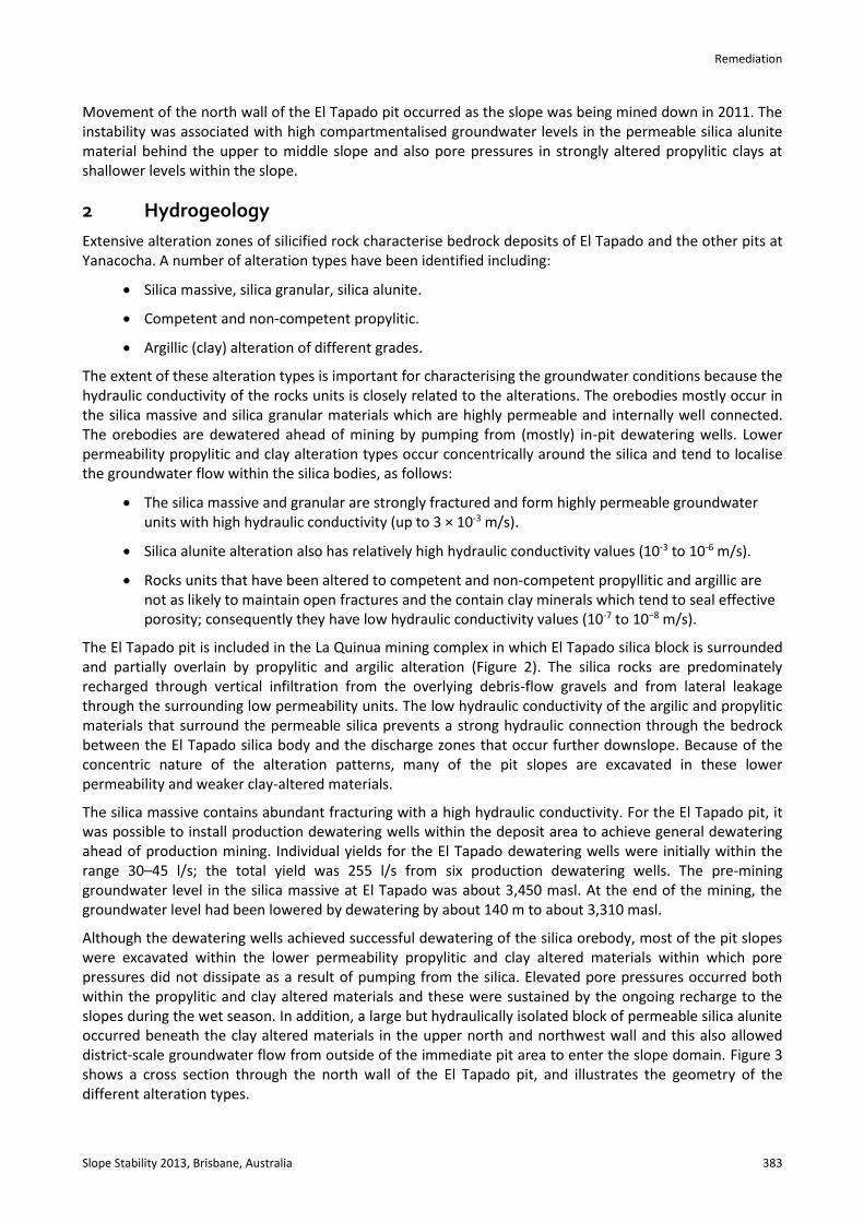
Movement of the north wall of the El Tapado pit occurred as the slope was being mined down in 2011. The instability was associated with high compartmentalised groundwater levels in the permeable silica alunite material behind the upper to middle slope and also pore pressures in strongly altered propylitic clays at shallower levels within the slope.
2 Hydrogeology
Extensive alteration zones of silicified rock characterise bedrock deposits of El Tapado and the other pits at Yanacocha. A number of alteration types have been identified including:
Silica massive, silica granular, silica alunite.
Competent and non-competent propylitic.
Argillic (clay) alteration of different grades.
The extent of these alteration types is important for characterising the groundwater conditions because the hydraulic conductivity of the rocks units is closely related to the alterations. The orebodies mostly occur in the silica massive and silica granular materials which are highly permeable and internally well connected. The orebodies are dewatered ahead of mining by pumping from (mostly) in-pit dewatering wells. Lower permeability propylitic and clay alteration types occur concentrically around the silica and tend to localise the groundwater flow within the silica bodies, as follows:
The silica massive and granular are strongly fractured and form highly permeable groundwater units with high hydraulic conductivity (up to 3 × 10⁻³ m/s).
Silica alunite alteration also has relatively high hydraulic conductivity values (10-3 to 10-6 m/s).
Rocks units that have been altered to competent and non-competent propyllitic and argillic are not as likely to maintain open fractures and the contain clay minerals which tend to seal effective porosity; consequently they have low hydraulic conductivity values (10-7 to 10−8 m/s).
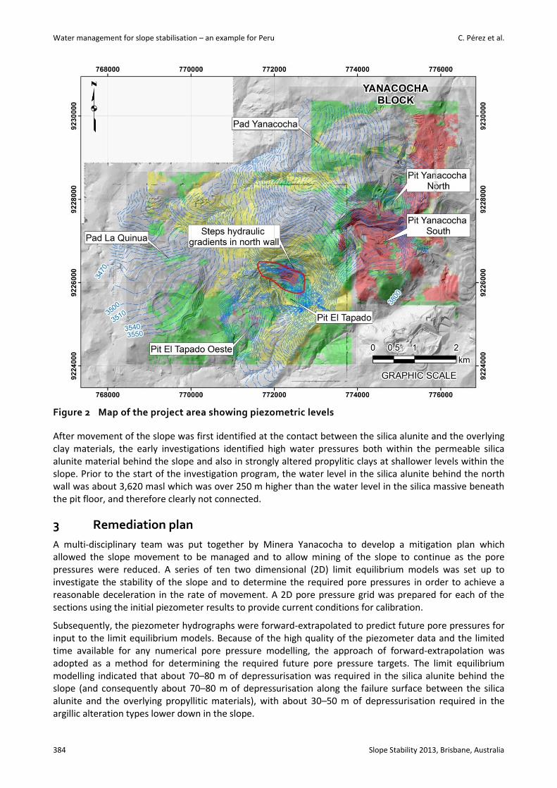
The El Tapado pit is included in the La Quinua mining complex in which El Tapado silica block is surrounded and partially overlain by propylitic and argilic alteration (Figure 2). The silica rocks are predominately recharged through vertical infiltration from the overlying debris-flow gravels and from lateral leakage through the surrounding low permeability units. The low hydraulic conductivity of the argilic and propylitic materials that surround the permeable silica prevents a strong hydraulic connection through the bedrock between the El Tapado silica body and the discharge zones that occur further downslope. Because of the concentric nature of the alteration patterns, many of the pit slopes are excavated in these lower permeability and weaker clay-altered materials.
The silica massive contains abundant fracturing with a high hydraulic conductivity. For the El Tapado pit, it was possible to install production dewatering wells within the deposit area to achieve general dewatering ahead of production mining. Individual yields for the El Tapado dewatering wells were initially within the range 30–45 l/s; the total yield was 255 l/s from six production dewatering wells. The pre-mining groundwater level in the silica massive at El Tapado was about 3,450 masl. At the end of the mining, the groundwater level had been lowered by dewatering by about 140 m to about 3,310 masl.
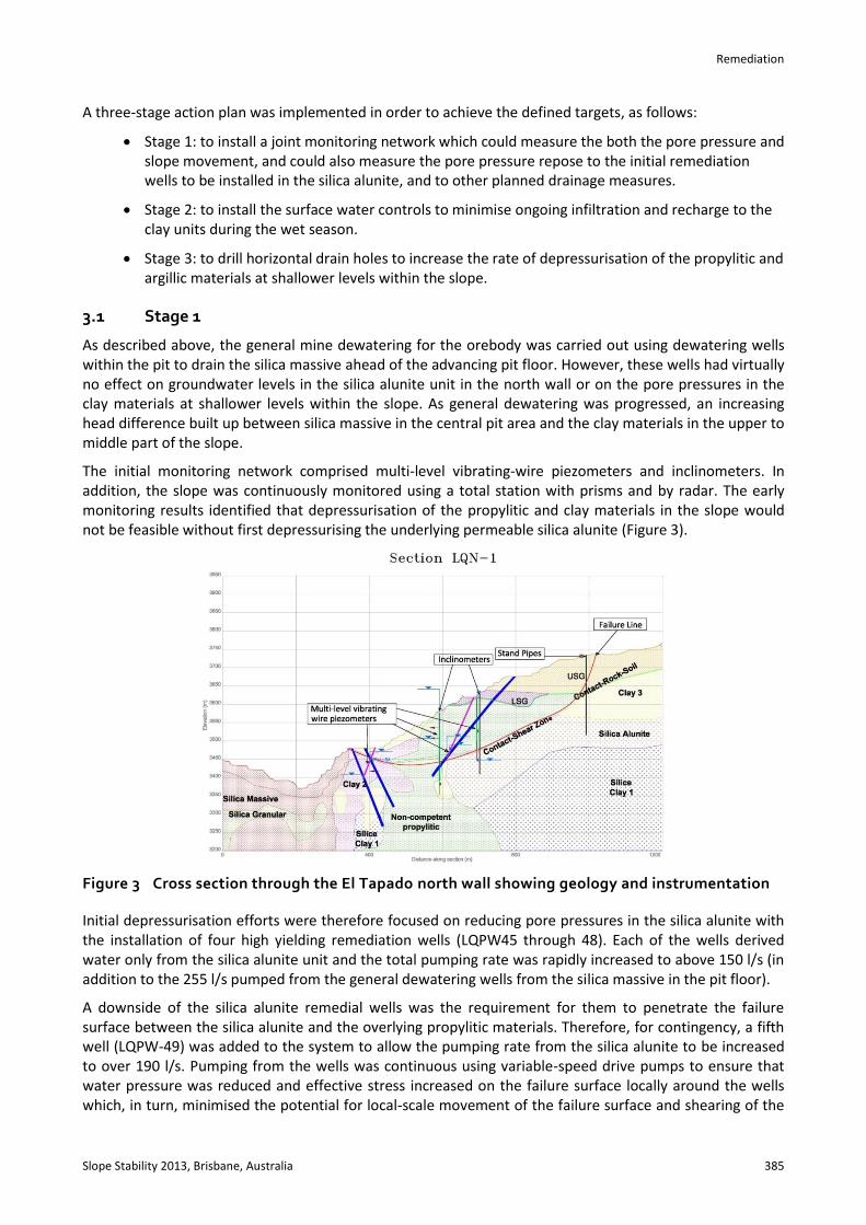
Although the dewatering wells achieved successful dewatering of the silica orebody, most of the pit slopes were excavated within the lower permeability propylitic and clay altered materials within which pore pressures did not dissipate as a result of pumping from the silica. Elevated pore pressures occurred both within the propylitic and clay altered materials and these were sustained by the ongoing recharge to the slopes during the wet season. In addition, a large but hydraulically isolated block of permeable silica alunite occurred beneath the clay altered materials in the upper north and northwest wall and this also allowed district-scale groundwater flow from outside of the immediate pit area to enter the slope domain. Figure 3 shows a cross section through the north wall of the El Tapado pit, and illustrates the geometry of the different alteration types.
Water management for slope stabilisation – an example for Peru C. Pérez et al.
384 Slope Stability 2013, Brisbane, Australia
Figure 2 Map of the project area showing piezometric levels
After movement of the slope was first identified at the contact between the silica alunite and the overlying clay materials, the early investigations identified high water pressures both within the permeable silica alunite material behind the slope and also in strongly altered propylitic clays at shallower levels within the slope. Prior to the start of the investigation program, the water level in the silica alunite behind the north wall was about 3,620 masl which was over 250 m higher than the water level in the silica massive beneath the pit floor, and therefore clearly not connected.
3 Remediation plan
A multi-disciplinary team was put together by Minera Yanacocha to develop a mitigation plan which allowed the slope movement to be managed and to allow mining of the slope to continue as the pore pressures were reduced. A series of ten two dimensional (2D) limit equilibrium models was set up to investigate the stability of the slope and to determine the required pore pressures in order to achieve a reasonable deceleration in the rate of movement. A 2D pore pressure grid was prepared for each of the sections using the initial piezometer results to provide current conditions for calibration.
Subsequently, the piezometer hydrographs were forward-extrapolated to predict future pore pressures for input to the limit equilibrium models. Because of the high quality of the piezometer data and the limited time available for any numerical pore pressure modelling, the approach of forward-extrapolation was adopted as a method for determining the required future pore pressure targets. The limit equilibrium modelling indicated that about 70–80 m of depressurisation was required in the silica alunite behind the slope (and consequently about 70–80 m of depressurisation along the failure surface between the silica alunite and the overlying propyllitic materials), with about 30–50 m of depressurisation required in the argillic alteration types lower down in the slope.
Remediation
Slope Stability 2013, Brisbane, Australia 385
A three-stage action plan was implemented in order to achieve the defined targets, as follows:
Stage 1: to install a joint monitoring network which could measure the both the pore pressure and slope movement, and could also measure the pore pressure repose to the initial remediation wells to be installed in the silica alunite, and to other planned drainage measures.
Stage 2: to install the surface water controls to minimise ongoing infiltration and recharge to the clay units during the wet season.
Stage 3: to drill horizontal drain holes to increase the rate of depressurisation of the propylitic and argillic materials at shallower levels within the slope.
3.1 Stage 1
As described above, the general mine dewatering for the orebody was carried out using dewatering wells within the pit to drain the silica massive ahead of the advancing pit floor. However, these wells had virtually no effect on groundwater levels in the silica alunite unit in the north wall or on the pore pressures in the clay materials at shallower levels within the slope. As general dewatering was progressed, an increasing head difference built up between silica massive in the central pit area and the clay materials in the upper to middle part of the slope.
The initial monitoring network comprised multi-level vibrating-wire piezometers and inclinometers. In addition, the slope was continuously monitored using a total station with prisms and by radar. The early monitoring results identified that depressurisation of the propylitic and clay materials in the slope would not be feasible without first depressurising the underlying permeable silica alunite (Figure 3).
Figure 3 Cross section through the El Tapado north wall showing geology and instrumentation
Initial depressurisation efforts were therefore focused on reducing pore pressures in the silica alunite with the installation of four high yielding remediation wells (LQPW45 through 48). Each of the wells derived water only from the silica alunite unit and the total pumping rate was rapidly increased to above 150 l/s (in addition to the 255 l/s pumped from the general dewatering wells from the silica massive in the pit floor).
A downside of the silica alunite remedial wells was the requirement for them to penetrate the failure surface between the silica alunite and the overlying propylitic materials. Therefore, for contingency, a fifth well (LQPW-49) was added to the system to allow the pumping rate from the silica alunite to be increased to over 190 l/s. Pumping from the wells was continuous using variable-speed drive pumps to ensure that water pressure was reduced and effective stress increased on the failure surface locally around the wells which, in turn, minimised the potential for local-scale movement of the failure surface and shearing of the
Water management for slope stabilisation – an example for Peru C. Pérez et al.
386 Slope Stability 2013, Brisbane, Australia
well casings. Where possible, any downtime of the pumps and consequent recovery of groundwater within the failure surface was prevented.
Additional multi-level vibrating wire piezometers were installed to allow monitoring of pore pressures within the silica alunite itself and to allow the effect of silica alunite pumping on the propylitic and clay altered materials to be monitored. The monitoring results showed that:
There was a rapid initial drop in water levels (over 60 m) throughout the entire silica alunite unit.
There was an increased rate of pore pressure dissipation in the overlying propylitic and clay−altered materials.
The observed displacement of the inclinometers, total station prisms and radar reduced, and a correlation was possible between the reduction in movement of the slope and the reduction in water levels in the silica alunite.
3.2 Stage 2
As part of water management and slope depressurisation plan, it was necessary to install surface water controls in the second stage. The surface water controls had four important goals:
To minimise the potential for the surface water to enter tension cracks that had developed in the upper part of the slope.
To shed water as rapidly as possible from the weak materials exposed in the slope and therefore reduce recharge to the weak (and low permeability) materials (Figures 4 and 5).
To minimise the extent to which infiltration to the non-competent propylitic materials could create high transient pore pressure in the near surface materials.
To minimise the extent to which erosion and back-cutting into the slope occurred due to surface water erosion.
Remediation
Slope Stability 2013, Brisbane, Australia 387
Figure 4 Downpipes installed to shed water rapidly from exposed weak materials in the slope. The downpipes connected into HDPE-lined trenches installed on each bench (visible in Figure 5)
Figure 5 HDPE-lined trenches installed on each bench where weak materials are exposed in the slope (see also the downpipes between benches)
Water management for slope stabilisation – an example for Peru C. Pérez et al.
388 Slope Stability 2013, Brisbane, Australia
3.3 Stage 3
Prior to the start of the horizontal drain program, the Mineral Yanacocha team re-evaluated the geology and determined specific targets and objectives for the program. Initially, the horizontal drains were installed into the non-competent propylitic material with drain collars on the 3,480 masl bench. The two phases of the program are summarised as follows:
3.3.1 Phase 1
15 gravity-flowing horizontal drains.
○ All 15 drains will be drilled into the high wall from the 3480 bench.
○ Initially, and to allow interactive monitoring, ‘every-other’ drain was drilled and brought online, and the influence of the drains on the piezometers was monitored prior to installing the ‘infill’ drains (Phase 2).
○ The drain lengths varied from 70 to 120 m, depending on location on the bench, and the total meterage was 1,460 m.
3.3.2 Phase 2
The results of the first 15 drains and their effect on the groundwater levels confirmed the necessity to drill additional drains, as follows:
○ A total of 12 drains from the 3,480 bench and collared between the previously drilled drains.
○ These were the even-numbered drains (2 through 30) on Figure 6.
○ The total meterage in Phase 2 was 1,510 m.
○ Drilling of the Phase 2 drains is illustrated on Figure 7.
Figure 6 General map of the north wall showing the location of the horizontal drains
Remediation
Slope Stability 2013, Brisbane, Australia 389
Figure 7 Drilling of the Phase 2 horizontal drains
4 Results
After a six month period in which mining of the slope had continued concurrently with a progressive lowering of pore pressures, it was determined that all pore pressure targets had been achieved and the slope could be mined to full depth, with the exception of a small zone of exposed clay material in the lower part of the slope which was below the influence of the pumping from the silica alunite wells and which could not be accessed for horizontal drain drilling (Figure 8).
Water management for slope stabilisation – an example for Peru C. Pérez et al.
390 Slope Stability 2013, Brisbane, Australia
Figure 8 Weak clay materials exposed in the lower part of the slope (note that the pit floor backfilling was carried out subsequent to completion of mining of the slope)
The performance of the five remediation wells in the silica alunite was as follows:
LQPW-45: pumping rate 49 l/s; 85 m water level drawdown in the nearest piezometer.
LQPW-46: pumping rate 25 l/s; 48 m water level drawdown in the nearest piezometer.
LQPW-47: pumping rate 33 l/s; 55 m water level drawdown in the nearest piezometer.
LQPW-48: pumping rate 14 l/s; 28 m water level drawdown in the nearest piezometer.
LQPW-49: pumping rate 35 l/s; 65 m water level drawdown in the nearest piezometer.
Overall, the pore pressures in the silica alunite were significantly lowered by pumping from the wells; a total of 60–130 m of drawdown was achieved throughout the silica alunite unit (from 3,610–3,620 masl to 3,480–3,560 masl). The pumping rate in LQPW-45 remained steady with time because of the high specific capacity of that well. The pumping rates in LQPW-46, 47, 48 and 49 gradually reduced with time as the amount of drawdown has progressively increased. The final total pumping rate was about 120 l/s which was still producing a minor drawdown on completion of mining.
Depressurisation targets for the upper slope were successfully achieved (Table 2, Figures 9 and 10). However, for the lower slope, there was still about 20 m pressure above the target within the clay altered materials in the lower part of the wall (Figure 8).
Remediation
Slope Stability 2013, Brisbane, Australia 391
Table 2 Summary of drawdowns achieved in the north wall piezometers
Figure 9 Vibrating wire piezometer hydrographs for Geotechnical Section 1
Water management for slope stabilisation – an example for Peru C. Pérez et al.
392 Slope Stability 2013, Brisbane, Australia
Figure 10 Vibrating wire piezometer hydrographs for Geotechnical Section 10
Bibliography
Brown, A. (1982) The influence and Control of Groundwater in Large Slopes, in Proceedings 3rd International Symposium Stability in Surface Mining, Chapter 3, pp. 19–39.
Burman, B.C. and Sullian, T. (1985) Dewatering and Depressurisation Studies for Development of the Lochiel Open Pit Mine, South Australia, Mine Water, Granada, Spain.
Neuzil, C.E. (2003) Hydromechanical Coupling in Geologic Processes, Hydrogeology Journal, Vol. 11. Read, J. and Stacey, P. (2009) Guidelines for Open Pit Slope Design, CSIRO Publishing. Savely, J.P. (1993) Slope management strategies for successful mining, Innovative Mine Design for 21st Century, Kingston. Sullivan, T. (2007) Hydromechanical Coupling and Pit Slope Movements, in Proceedings International Symposium on Rock Slope
Stability in Open Pit Mining and Civil Engineering (Slope07), Y. Potvin (ed), 12‒14 September 2007, Perth, Australia, Australian Centre for Geomechanics, Perth, pp. 3–43.