64
Turn to the ExpeS DISTRIBUTION S Y S TEMS Water Piping and Pumps
| Date post: | 07-Jul-2016 |
| Category: |
Documents |
| Upload: | meshal-al-mutairi |
| View: | 56 times |
| Download: | 7 times |

Turn to the ExpertS.
DISTRIBUTION SYSTEMS
Water Piping and
Pumps

Technical Development Programs (TDP) are modules of technical training on HV AC theory, s ·stem design, equipment selection and application topics . They are targeted at engineers and C:esigners who wish to develop their knowledge in this field to effectively design, specify, sell or apply HV AC equipment in commercial applications.
Although TDP topics have been developed as stand-alone modules, there are logical groupings of topics . The modules within each group begin at an introductory level and progress to ad\ anced levels . The breadth of this offering allows for customization into a complete HV AC uniculum - from a complete HVAC design course at an introductory-level or to an advanced
le\·el design course. Advanced-level modules assume prerequisite knowledge and do not review basic concepts .
I ntrod uction to HVAC
Psychrometries
Equipment
Systems
Controls
Applications
Water piping and pumping is a fundamentals topic of HVAC design. The correct layout, selection and sizing of the piping system and associated hydronic components is required to properly deliver chilled and hot water as required to maintain comfort conditions . Piping connections at various equipment are covered, along with piping anangements for chilled water systems. Pump basics, pipe sizing, and a pump selection example complete the TDP.
© 2005 Carrier Corporation. A l l rights reserved.
The information i n this manual i s offered a s a general guide for the use o f industry and consulting engineers i n designing systems. Judgment is required for application of this information to specific installations and design applications. Carrier is not responsible for any uses made of this information and assumes no responsibility for the performance or desirability of any resulting system design.
The information in this publication is subject to change without notice. No part of this publication may be reproduced or transmitted in any form or by any means, electronic or mechanical, for any purpose, without the express written permission of Carrier Corporation.
Printed in Syracuse, NY
CARR I ER CORPORATION Carrier Parkway Syracuse, NY 1 322 1 , U.S.A.

Table of Contents
Introduction . . . . . . . . . . . . . . . . . . . . . . . . . . . . . . . . . . . . . . . . . . . . . . . . . . . . . . . . . . . . . . . . . . . . . . . . . . . . . . . . . . . . . . . . . . . . . . . . . . . . . . . . . . . . . . . . . . . . . . . . . . . . . . . . . . . . . 1 Types of Piping Systems . . . . . . . . . . . . . . . . . . . . . . . . . . . . . . . . . . . . . . . . . . . . . . . . . . . . . . . . . . . . . . . . . . . . . . . . . . . . . . . . . . . . . . . . . . . . . . . . . . . . . . . . . . . . . . . . . 1
Closed-Loop (Evaporator) . . . . . . . . . . . . . . . . . . . . . . . . . . . . . . . . . . . . . . . . . . . . . . . . . . . . . . . . . . . . . . . . . . . . . . . . . . . . . . . . . . . . . . . . . . . . . . . . . . . . . . . . . . . 1 Open-Loop (Condenser) . . . . . . . . . . . . . . . . . . . . . . . . . . . . . . . . . . . . . . . . . . . . . . . . . . . . . . . . . . . . . . . . . . . . . . . . . . . . . . . . . . . . . . . . . . . . . . . . . . . . . . . . . . . . . . 2 Once-Thru . . . . . . . . . . . . . . . . . . . . . . . . . . . . . . . . . . . . . . . . . . . . . . . . . . . . . . . . . . . . . . . . . . . . . . . . . . . . . . . . . . . . . . . . . . . . . . . . . . . . . . . . . . . . . . . . . . . . . . . . . . . . . . . . . . . . 2
Water Distribution Systems . . . . . . . . . . . . . . . . . . . . . . . . . . . . . . . . . . . . . . . . . . . . . . . . . . . . . . . . . . . . . . . . . . . . . . . . . . . . . . . . . . . . . . . . . . . . . . . . . . . . . . . . . . . . . 3 1 -Pipe Systems . . . . . . . . . . . . . . . . . . . . . . . . . . . . . . . . . . . . . . . . . . . . . . . . . . . . . . . . . . . . . . . . . . . . . . . . . . . . . . . . . . . . . . . . . . . . . . . . . . . . . . . . . . . . . . . . . . . . . . . . . . . . . 3 2-Pipe Systems . . . . . . . . . . . . . . . . . . . . . . . . . . . . . . . . . . . . . . . . . . . . . . . . . . . . . . . . . . . . . . . . . . . . . . . . . . . . . . . . . . . . . . . . . . . . . . . . . . . . . . . . . . . . . . . . . . . . . . . . . . . . . 4 3-Pipe Systems . . . . . . . . . . . . . . . . . . . . . . . . . . . . . . . . . . . . . . . . . . . . . . . . . . . . . . . . . . . . . . . . . . . . . . . . . . . . . . . . . . . . . . . . . . . . . . . . . . . . . . . . . . . . . . . . . . . . . . . . . . . . . 5 4-Pipe Systems . . . . . . . . . . . . . . . . . . . . . . . . . . . . . . . . . . . . . . . . . . . . . . . . . . . . . . . . . . . . . . . . . . . . . . . . . . . . . . . . . . . . . . . . . . . . . . . . . . . . . . . . . . . . . . . . . . . . . . . . . . . . . 6
Direct and Reverse Return Systems . . . . . . . . . . . . . . . . . . . . . . . . . . . . . . . . . . . . . . . . . . . . . . . . . . . . . . . . . . . . . . . . . . . . . . . . . . . . . . . . . . . . . . . . . . . . . . . . . 7 Direct Return . . . . . . . . . . . . . . . . . . . . . . . . . . . . . . . . . . . . . . . . . . . . . . . . . . . . . . . . . . . . . . . . . . . . . . . . . . . . . . . . . . . . . . . . . . . . . . . . . . . . . . . . . . . . . . . . . . . . . . . . . . . . . . . . 7 Reverse Return . . . . . . . . . . . . . . . . . . . . . . . . . . . . . . . . . . . . . . . . . . . . . . . . . . . . . . . . . . . . . . . . . . . . . . . . . . . . . . . . . . . . . . . . . . . . . . . . . . . . . . . . . . . . . . . . . . . . . . . . . . . . . 8
Water Piping Components and Accessories . . . . . . . . . . . . . . . . . . . . . . . . . . . . . . . . . . . . . . . . . . . . . . . . . . . . . . . . . . . . . . . . . . . . . . . . . . . . . . . . . . . . 8 Pipe Materials . . . . . . . . . . . . . . . . . . . . . . . . . . . . . . . . . . . . . . . . . . . . . . . . . . . . . . . . . . . . . . . . . . . . . . . . . . . . . . . . . . . . . . . . . . . . . . . . . . . . . . . . . . . . . . .. . .. . . . . . . . . . . . 9 Joints . . . . . . . . . . . . . . . . . . . . . . . . . . . . . . . . . . . . . . . . . . . . . . . . . . . . . . . . . . . . . . . . . . . . . . . . . . . . . . . . . . . . . . . . . . . . . . . . . . . . . . . . . . . . . . . . . . . . . . . . . . . . . . . . . . . . . . . . . . . . 9 Fittings . . . . . . . . . . . . . . . . . . . . . . . . . . . . . . . . . . . . . . . . . . . . . . . . . . . . . . . . . . . . . . . . . . . . . . . . . . . . . . . . . . . . . . . . . . . . . . . . . . . . . . . . . . . . . . . . . . . . . . . . . . . . . . . . . . . . . . . 1 0 Valves . . . . . . . . . . . . . . . . . . . . . . . . . . . . . . . . . . . . . . . . . . . . . . . . . . . . . . . . . . . . . . . . . . . . . . . . . . . . . . . . . . . . . . . . . . . . . . . . . . . . . . . . . . . . . . . . . . . . . . . . . . . . . . . . . . . . . . . . 1 1 Hydronic System Components . . . . . . . . . . . . . . . . . . . . . . . . . . . . . . . . . . . . . . . . . . . . . . . . . . . . . . . . . . . . . . . . . . . . . . . . . . . . . . . . . . . . . . . . . . . . . . . . . . 1 6
Strainers . . . . . . . . . . . . . . . . . . . . . . . . . . . . . . . . . . . . . . . . . . . . . . . . . . . . . . . . . . . . . . . . . . . . . . . . . . . . . . . . . . . . . . . . . . . . . . . . . . . . . . . . . . . . . . . . . . . . . . . . . . . . . . . . . 1 6 Expansion Tanks . . . . . . . . . . . . . . . . . . . . . . . . . . . . . . . . . . . . . . . . . . . . . . . . . . . . . . . . . . . . . . . . . . . . . . . . . . . . . . . . . . . . . . . . . . . . . . . . . . . . . . . . . . . . . . . . . . . . 1 6 Air Separators . . . . . . . . . . . . . . . . . . . . . . . . . . . . . . . . . . . . . . . . . . . . . . . . . . . . . . . . . . . . . . . . . . . . . . . . . . . . . . . . . . . . . . . . . . . . . . . . . . . . . . . . . . . . . . . . . . . . . . . . 18 Air Vents . . . . . . . . . . . . . . . . . . . . . . . . . . . . . . . . . . . . . . . . . . . . . . . . . . . . . . . . . . . . . . . . . . . . . . . . . . . . . . . . . . . . . . . . . . . . . . . . . . . . . . . . . . . . . . . . . . . . . . . . . . . . . . . . 18 Thermometers , Gauges, Pete ' s Plugs . . . . . . . . . . . . . . . . . . . . . . . . . . . . . . . . . . . . . . . . . . . . . . . . . . . . . . . . . . . . . . . . . . . . . . . . . . . . . . . . . . . . . 1 9 Pipe Hangars and Anchors . . . . . . . . . . . . . . . . . . . . . . . . . . . . . . . . . . . . . . . . . . . . . . . . . . . . . . . . . . . . . . . . . . . . . . . . . . . . . . . . . . . . . . . . . . . . . . . . . . . . . 1 9 Volume Tanks . . . . . . . . . . . . . . . . . . . . . . . . . . . . . . . . . . . . . . . . . . . . . . . . . . . . . . . . . . . . . . . . . . . . . . . . . . . . . . . . . . . . . . . . . . . . . . . . . . . . . . . . . . . . . . . . . . . . . . . . 20
Typical Piping Details at Equipment . . . . . . . . . . . . . . . . . . . . . . . . . . . . . . . . . . . . . . . . . . . . . . . . . . . . . . . . . . . . . . . . . . . . . . . . . . . . . . . . . . . . . . . . . . . . . 2 1 Chillers . . . . . . . . . . . . . . . . . . . . . . . . . . . . . . . . . . . . . . . . . . . . . . . . . . . . . . . . . . . . . . . . . . . . . . . . . . . . . . . . . . . . . . . . . . . . . . . . . . . . . . . . . . . . . . . . . . . . . . . . . . . . . . . . . . . . . . . 2 1 AHU Coil or Fan Coil . . . . . . . . . . . . . . . . . . . . . . . . . . . . . . . . . . . . . . . . . . . . . . . . . . . . . . . . . . . . . . . . . . . . . . . . . . . . . . . . . . . . . . . . . . . . . . . . . . . . . . . . . . . . . . . . 22 Pumps . . . . . . . . . . . . . . . . . . . . . . . . . . . . . . . . . . . . . . . . . . . . . . . . . . . . . . . . . . . . . . . . . . . . . . . . . . . . . . . . . . . . . . . . . . . . . . . . . . . . . . . . . . . . . . . . . . . . . . . . . . . . . . . . . . . . . . . . . 22
System Piping Arrangements . . . . . . . . . . . . . . . . . . . . . . . . . . . . . . . . . . . . . . . . . . . . . . . . . . . . . . . . . . . . . . . . . . . . . . . . . . . . . . . . . . . . . . . . . . . . . . . . . . . . . . . . 23 Parallel and Series Chiller Evaporators . . . . . . . . . . . . . . . . . . . . . . . . . . . . . . . . . . . . . . . . . . . . . . . . . . . . . . . . . . . . . . . . . . . . . . . . . . . . . . . . . . . . . 23 Single Water-Cooled Chiller Loop . . . . . . . . . . . . . . . . . . . . . . . . . . . . . . . . . . . . . . . . . . . . . . . . . . . . . . . . . . . . . . . . . . . . . . . . . . . . . . . . . . . . . . . . . . . . 24 Multiple Water-Cooled Chiller Loop with Dedicated Pumps . . . . . . . . . . . . . . . . . . . . . . . . . . . . . . . . . . . . . . . . . . . . . . . . . . . . 24 Multiple Water-Cooled Chillers with Manifolded Pumps . . . . . . . . . . . . . . . . . . . . . . . . . . . . . . . . . . . . . . . . . . . . . . . . . . . . . . . . . 25 Primary-Secondary Chilled Water System . . . . . . . . . . . . . . . . . . . . . . . . . . . . . . . . . . . . . . . . . . . . . . . . . . . . . . . . . . . . . . . . . . . . . . . . . . . . . . . . 25 Primary-Only, Variable-Flow Chilled Water System . . . . . . . . . . . . . . . . . . . . . . . . . . . . . . . . . . . . . . . . . . . . . . . . . . . . . . . . . . . . . . . . 26 Chiller Head Pressure Control . . . . . . . . . . . . . . . . . . . . . . . . . . . . . . . . . . . . . . . . . . . . . . . . . . . . . . . . . . . . . . . . . . . . . . . . . . . . . . . . . . . . . . . . . . . . . . . . . . . 27
Head Pressure Control Piping Methods with Diverting Valve . . . . . . . . . . . . . . . . . . . . . . . . . . . . . . . . . . . . . . . . . . . . . . 28 Head Pressure Control Piping Method with VFD or Modulating Valve . . . . . . . . . . . . . . . . . . . . . . . . . . . . . . . 29
Pump Basics and Types of Pumps . . . . . . . . . . . . . . . . . . . . . . . . . . . . . . . . . . . . . . . . . . . . . . . . . . . . . . . . . . . . . . . . . . . . . . . . . . . . . . . . . . . . . . . . . . . . . . . . . 29 Pump Curve . . . . . . . . . . . . . . . . . . . . . . . . . . . . . . . . . . . . . . . . . . . . . . . . . . . . . . . . . . . . . . . . . . . . . . . . . . . . . . . . . . . . . . . . . . . . . . . . . . . . . . . . . . . . . . . . . . . . . . . . . . . . . . . 32 Selection . . . . . . . . . . . . . . . . . . . . . . . . . . . . . . . . . . . . . . . . . . . . . . . . . . . . . . . . . . . . . . . . . . . . . . . . . . . . . . . . . . . . . . . . . . . . . . . . . . . . . . . . . . . . . . . . . . . . . . . . . . . . . . . . . . . . . 35 Centrifugal Pump Types . . . . . . . . . . . . . . . . . . . . . . . . . . . . . . . . . . . . . . . . . . . . . . . . . . . . . . . . . . . . . . . . . . . . . . . . . . . . . . . . . . . . . . . . . . . . . . . . . . . . . . . . . . . . 36

Pipe Sizing and Pump Selection Example ..................................................................................... 37 Step 1: Determine Water Velocity in Piping . . . . ......... . . . .. .. .... . . . . . . . . . . . . . . ...... . . ... . . . . . . . . . . . .. . . . . . . . . . ...... 3 7 Step 2 : Determining Piping Friction Losses ..................... ..... . . . . . .............................................. 3 7 Step 3 : Gather Job Specific Component Pressure Drops and Design Data .... .......................... 3 8 Step 4 : Review the Highest Pressure Drop Circuit and Calculate Water Flows ........................ 39 Step 5 : Size the Pipe; Find the Friction Rate/ 1 00 ft . . . . . . . . . . . . . . . . . . . . . . . . . . . . . . . . . . . . . . . . . . . . . . . . . . . . . . . . . . . . . . . . . . 40 Step 6 : Find the Longest Circuit Pressure Drop . . . . . . . . . . . . . . . . . . . . . . . . . . . . . . . . . . . . . . . . . . . . . . . . . . . . . . . . . . . . . . . . . . . . . . . . 4 1 Step 7 : Sum All the Pressure Drops for Pump Selection . . . . . . . . . . . . . . . . . . . . . . . . . . . . . . . . . . . . . . . . . . . . . . . . . . . . . . . . . . 42 Step 8 : Size the Chilled Water Loop ........................................................................................ . 43 Step 9 : Check Evaporator Loop Volume ...... .............................. ............................................. . 45 Piping System Calculator Tool ...................................... . ........................................................... 46
Summary ........................................................................................................................................ 46 Work Session ......... . ....................................................................................................................... 4 7 Appendix ........................................................................................................................................ 49
References .................................................................................................................................. 49 Charts and Tables ......... ............................................................................. ................................. 49
Chart 1 - Friction Loss for Closed Loop . . . . . . . . . . . . . . . . . . . . . . . . . . . . . . . . . . . . . . . . . . . . . . . . . . . . . . . . . . . . . . . . . . . . . . . . . . . . . . . 50 Chart 2 - Friction Loss for Open Loop .................................................................................. 5 1 Chart 3 - Friction Loss for Closed and Open Copper Tubing System ..... . ............ .. . . . . .... . . . . . . 52 Table 4 - Physical Properties of Steel Pipe ............................................................. . .. . .. . .. . . . . . 53 Table 5 - Friction Loss of Valves in Equivalent Length of Straight Pipe ............. .. . . . . . . . . . .. . .. 54 Table 6 - Friction Loss of Pipe Fittings in Equivalent Feet of Straight Pipe . .... . .. ... .. . .. . . . ..... 55 Table 7- Special Fitting Losses in Equivalent Feet of Straight Pipe ........ . . . ........ . . . . . . . . . . . . .. . .. 56 Table 8 - Control Valves and Strainer Losses in Equivalent Feet of Straight Pipe . . . . . . . . . . . . . . . 57
Work Session Answers ............................................................................ . .. . .. . . . .. . . . . . . . . . . . . . . . . . . . . . . . 53

WATER P I P I N G AN D P U M PS
Introduction
In this TDP module we will cover major topics associated with chilled water piping, and to a limited extent, hot water piping. We will discuss the three types of piping systems and the four basic piping distribution designs used to supply and return water to HV AC hydronic equipment.
There are important components and accessories that are required to complete a water piping system. These include valves, tanks, and air eliminators . We will examine these system components and define their role in the total hydronic system.
After examining some typical piping hook-ups to commercial HVAC equipment, we will diagram and discuss popular piping arrangements, such as primary secondary and primary variable flow. We will then discuss a popular pipe-sizing tool from a noted pump manufacturer that streamlines the sizing process. We will also examine types of water pumps used in HVAC systems and their characteristics and applications .
Upon completion of this TDP, the reader should feel comfortable identifying, selecting, and applying the maj or components of water piping systems .
Types of Piping Systems
Before piping design can be discussed in detail, you must first have an understanding of the three basic types of piping systems: closed-loop, open-loop, and once-thru.
Closed-Loop (Evaporator) In a closed-loop piping system,
the water is contained within a closed piping system, or loop, through which it circulates . While there may be some nominal contact with the air depending on the type of tank used, the system is considered closed to the environment. Typically , closed-loop systems are chemically treated to control corrosion, scale, slime, and algae within the piping but their chemical treatment requirements typically are not as extensive as an open-loop .
P i ing
Includes: • A chiller and/or a boiler
Expansion Tank
ss• F
• Coils that produce cooling or heating
• Two or three-way valves to control the coils
• Piping and pump to circulate water • An expansion tank (insignificant water contact with air}
Figure 1 Example of a Closed-Loop Piping System
D ist ributio n Systems -------------- --------- --- ------- Thm to the Expert&
1

WATE R P I P I N G AN D P U M PS
Open-Loop (Condenser)
In an open-loop piping system, the water is in constant contact with the air and the system is therefore open to the atmosphere . A typical example of an open-loop system is a recirculating condenser water system with a cooling tower where the water is circulated through the cooling tower, sprayed over the tower media surface, collected into the tower basin, circulated through the condenser, and then sent back through the cooling tower.
Once-Thru
�w���d';��!�d ·����· ------� 94 to 95° F
3 gpm/ton Chiller
Condenser Water Pump 85° F Cooling Tower
• The water-cooled condenser is typically part of a water-cooled chiller or water-cooled package unit
• A cooling tower rejects the condenser heat to the atmosphere • Flow rates and temperatures are industry standards for North America • Piping and pumps circulate water • Water is reused and exposed to the ambient conditions
in the cooling tower
Figure 2 Example of an Open-Loop Recirculating System
In this type of system, water passes through the system once and is then discharged. An example of a once-thru system would be a chiller with river water piped into its water-cooled
' ·--..., .J.
= · Chiller with Condenser
�-----�--------Pump
Once-Thru
Source of water (river)
• Much less common due to environmental concerns
• Water is sent to waste or returned back to source
• Large consumption of water
• Source example: river, lake, well
Figure 3 Example of a Once- Thru System
Optional ll
WATER P I P I N G AN D P U M PS
Water Distribution Systems
There are four main types of water distribution systems . They are defined by the number of pipes used in the system - 1 -pipe, 2-pipe, 3 -pipe, and 4-pipe. While this TDP will discuss primarily chilled water and condenser water system piping system design, it is important to understand the evolution from 1 -pipe into the other three systems, all of which are used for heating as well as cooling.
1-Pipe Systems
A 1 -pipe water distribution system is a system that has a one main pipe looping around the building and then returning.
This pipe is both the supply and return main. Its size is constant throughout, and all of the water in the system flows through it feeding
Typical Heating\
Terminal \
one or more zone heating terminals . Figure 4 A small amount of water is 1-Pipe Distribution System
induced to leave the main at each
Monoflow"' Fitting
Main Piping Loop Supply and Return ( 1 size throughout)
Typical Heating-Only
System
riser by the use of a special flow fitting used on 1 -pipe systems, sometimes referred to as a "monoflow" fitting. These fittings create a pressure drop in the main equal to or greater than the pressure drop through the riser, runout, zone terminal unit, and return piping.
Control of flow rate to the zone terminal units in a 1 -pipe system is often difficult to achieve. The pressure drop from the point where water leaves the main to where it returns is small and small changes in resistance in this line result in large changes in flow rate. As a result, many 1 -pipe systems avoid flow rate control at the zone terminals and achieve capacity control by regulating airflow over the zone terminals instead .
Some advantages of the 1 -pipe system include the simple design of the system that requires one pipe size . This simplicity of design leads to easy installation and low installed cost.
However, 1 -pipe systems have several disadvantages. 1 The pumping head is generally higher than that in other sys
tems because of the resistances occurring in series. That means the pump and pump energy is larger than other distribution systems of comparable size.
D istrib utio n System s -------------- - - ---------- ------- Turn to the Experts�
3

WATER P I P I N G AN D P U M PS
The change in water temperature as the water moves through the system (the water gets colder after each successive terminal because of mixing) creates the possible need of larger units at the end of the main, which will complicate the selection of the zone terminal units and add cost due to oversized units near the end . Also, at part load, the end unit may be over or under capacity.
In order to keep the pressure loss through the unit coils low, the water velocity through the coils must be kept low. This results in coils with large tube diameter, a greater number of tubes in parallel, or larger coils than used with other distribution systems . Therefore, a physical space and terminal cost penalty exist when a 1 -pipe system is used .
The 1 -pipe system is poorly suited to chilled water distribution for several reasons . The water quantity used in chilled-water systems is usually considerably higher than that used for heating because the unit coils work on smaller temperature differentials in the cooling mode than in the heating mode. In order to economically accommodate higher flow rate, zone terminals used for chilled water would need to be redesigned so they are not prohibitively large, expensive, or space-consummg.
2-Pipe Systems
The 2-pipe water distribution system is used with both heating and cooling equipment containing water coils . It is equally useful for room fan coil units and medium or large central air handlers using combination hot water and chilled water coils . The 2-pipe system can be used to distribute either hot or cold water, or alternate between the two. The same piping is used for both heating and cooling so there must be a definite outdoor temperature, which is called the "changeover temperature," or some other indicator of building load, at which point the hot water in the piping is replaced by the chilled water and vice versa.
Some 2-pipe fan coil units are equipped with electric heat in addition to the heating capability of the hot water coil. This "touch up" electric heat can be used if heating is required for a fan coil but the system is still not changed over to the heating mode.
Figure 5
Summer Mode
�� ;? t:::ltlJ� \_Return Piping
2-Pipe Reverse Return Distribution System
There are two forms of 2-pipe water distribution systems in common use: 2-pipe direct return and 2-pipe reverse return. Direct and reverse return will be covered later.
In a 1 -pipe system, the supply and return main is the same pipe. The quantity of water flowing through the main is approximately constant and the main is built of one diameter pipe throughout its length. On the other hand, in the 2-pipe system, the supply and return mains are separate pipes and water leaving the supply main goes into the return main. As water leaves the
Tum to the Experts:' _ _____ ________ __________ D_i_s_tr_ i_ b_u_ t i_o_ n_ S_ y;;..s_ t_ e_ m_s 4
WATER P I P I N G AN D P U M PS
supply main and goes through the terminal units, the quantity of water flowing in the main is reduced, so the pipe diameter can be reduced. The opposite is true for the return main, which starts out small at the furthest terminal and has to be increased in size as water enters it.
Advantages of 2-pipe systems include the fact that a higher friction loss can be taken in both the piping and the zone terminal units and still have a total pumping head lower than that in the same size 1-pipe system because the zone terminals are in parallel water circuits, not series. Also, it is easier to balance the flow to each unit in this system than in the 1-pipe system, assuming branch balancing valves are installed in the piping as the system is installed. Another advantage of 2-pipe systems is that the water temperature entering each zone terminal will be the same in temperature because the return water from each terminal unit does not mix with the supply water in the supply main.
However, the installed cost is greater than that for a 1-pipe system. In systems of the same size, even though the average pipe diameter in the 2-pipe system is smaller than that in the 1 -pipe system, the extra pipe and greater number o f fittings means that this system will have a greater first cost. Like the 1-pipe system, the 2-pipe system distributes only a common temperature fluid to the zone terminals. Because the system cannot
deliver hot water or chilled water simultaneously to the coils, it must be in either the heating or cooling mode. To change over from heating to cooling, the water in the mains must be completely circulated through the chiller and back to the unit before any cooling is available at the zones. Changeover takes time. It is not practical to plan to change over frequently. Seasonal changeover is the most common method used. Two-pipe supplemental heating systems are also quite common, both for separate perimeter heating and zone reheat at the terminals.
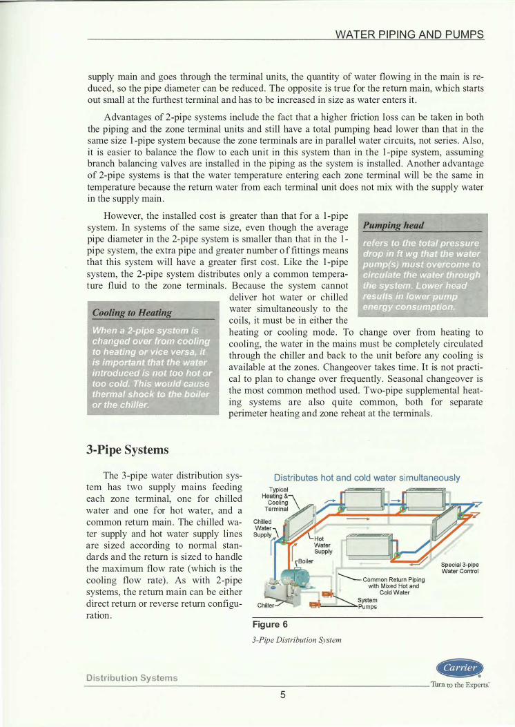
3-Pipe Systems
The 3 -pipe water distribution system has two supply mains feeding each zone terminal, one for chilled water and one for hot water, and a common return main. The chilled water supply and hot water supply lines are sized according to normal standards and the return is sized to handle the maximum flow rate (which is the cooling flow rate). As with 2-pipe systems, the return main can be either direct return or reverse return configuration.
Distributes hot and cold water simultaneously
Figure 6
............._ Common Return Piping with Mixed Hot and
� ColdWater -� System '1!!!1'1'-----'::... pumps
3-Pipe Distribution System
Special 3-pipe Water Control
D istri bution Systems --------------------------------- Turn to the Experts:"
5

WATER P I P I N G AN D P U M PS
Because of the two supply mains to each zone terminal, there is always hot and cold water present at the entrance to the zone coil ready to be used when needed . This gives any fan coil or air handler supplied by the 3 -pipe water distribution system the ability to heat or cool at any time. No changeover from summer to winter cycle is needed in the 3 -pipe system. ASHRAE 90.1
-----------------------------
However, the operating cost of this system can become prohibitively high because of the mixing of hot and cold return water. It is important to be familiar with 3 -pipe systems because they have been installed in existing buildings and are still in use.
4-Pipe Systems
The 4-pipe water distribution system is actually two, 2-pipe systems in parallel; each system consisting of its own supply and return main. One system is always distributing chilled water to the units and returning it to the chiller. The other is distributing hot water to the units and returning the water to the boiler. Unlike the 3 -pipe system, there is no mixing of hot Distributes hot and cold water simultaneously and cold water. By using two separate coils in each zone terminal unit, or one coil with a separate cooling and heating circuit, the heating and cooling systems are completely separated . The chilled water flows through a cooling coil and the hot water flows through a separate heating coil. At no point are the two circuits connected . In a 4-pipe water distribution system, each terminal unit can become a separate zone of control, with its own thermostat. Both hot and cold water are available to all units at one time.
Figure 7 4-Pipe Distribution System
Four-pipe distribution systems are actually two 2-pipe systems in parallel. This system offers both hot and chilled water to all zones simultaneously, enabling the system to meet cooling and heating loads whenever and wherever they occur. There is no need for seasonal or more frequent changeover. The hot and chilled water circuits are completely separate and the two water streams are never mixed . The design methods, valves, and controls are similar to 2-pipe and 3 -pipe systems.
A 4-pipe system with a fossil fuel-fired boiler can deliver a competitive or lower operating cost than some 2-pipe systems with "touch-up" electric heat built into the unit. That is because the electric heaters in the 2-pipe unit must sometimes operate more often than is expected and electric resistance heat is expensive, and the heaters may require a larger building electric service . This operation occurs prior to the entire system changeover to heating. Fossil fuel rates typically offer an advantage to electric rates .
Dist ribution System s Tum to the Expert& _________________________________________________ ___::.__ __
6

WATER P I P I N G AN D P U M PS
However, 4-pipe systems have a higher installed price than 2-pipe and most 3 -pipe systems . The extra pipe and valves at the zone terminals tend to make the 4-pipe system the most costly in terms of installed cost. Four-pipe systems also require terminal units with dual coils or a 2-circuit coil, which costs more. Also, there are four pipes to run throughout the building, which takes more time and consumes more space for piping than the other systems .
For commercial buildings, the choice comes down to 2-pipe versus 4-pipe designs . The comfort and control advantage of 4-pipe over 2-pipe must be weighed against the higher installed cost of the 4-pipe system. Where the building configuration and layout of spaces may require long periods of both heating and cooling simultaneously, and occupant comfort is a requirement, 4-pipe makes the most sense. When the building lends itself to a seasonal changeover without large compromises in comfort, 2-pipe is suitable.
Direct and Reverse Return Systems
Closed-loop systems can be further classified as direct return or reverse return.
Direct Return
The direct return system allows piping to be run in the most direct path to optimize piping costs . The disadvantage is that the flow at each fan coil unit or air handler usually needs to be balanced using a balancing valve. The length of the water circuit through the supply and return piping to each fan
� 1, Unrt-2 � l�rt-3 � 1, Unit-4 � coil or air handler is different in direct Supply
. . :}!{] C;.o
return piping. Fan coils close to the pump receive greater flow rate than those further away unless balancing is accomplished.
Open-loop systems such as the condenser water system discussed earlier with a cooling tower are always direct return since individual terminals don't exist and balancing is relatively simple.
Return Balancing Valves
• Water enters Unit-1 from supply
• Water leaves Unit-1 and returns directly to source
• The first unit supplied is the first returned
• Unequal circuit pressure drops result
• Circuit pressure drop through Unit-1 < Unit-2 < Unit-3 < Unit-4 < Unit-5
• Balancing valves are a necessity
Figure 8 Direct Return Horizontal System Layout
Distribution Systems --------------------------------Tum to the Experts."
7

WATER P I P I N G AN D P U M PS
Reverse Return
The reverse return system is piped so that the length of the water circuit through the supply and return piping to each fan coil or air handler is essentially the same. Therefore, pressure drops are basically equal . Buildings such as hotels with multiple identical fan coil 1, Unit-1 JJ 1, Unit-2 � 1, untt-3 I] 1, Unit-4 I] units with identical flows are excel-lent candidates for reverse return systems.
Reverse return has greater pipe lengths and cost. However, the cost of adding a balancing valve for each fan coil using a direct return system could offset the additional costs of the added reverse return piping.
If the individual fan coil or airhandling unit water pressure drops are not reasonably close to each other, engineers will often specify balancing valves anyway, regardless of the piping arrangement.
Supply
Return
• Return header flow is same direction as supply flow
• Water leaves Unit-1 and goes all the way around in returning to source
• The first unit supplied is the last returned
• Circuit pressure drop through Unit-1 = Unit-2 = Unit-3 = Unit-4 = Unit-S
• Balancing valves may be eliminated
Figure 9 Reverse Return Horizontal System Layout
Water Piping Components and Accessories
There are many, varied, components that make up all water, and air-water systems . Pipe, fittings, valves, strainers, pumps, chillers, air-handling units, cooling towers, expansion tanks, air separators, Pete ' s plugs, thermometers, gauges, air vents, pipe supports, and possibly a volume tank are all included. Following are descriptions of hydronic components that are used in chilled water piping systems.
Distribution S yst ems Turn to the ExpertS: ____________________________ ____::__ __
8

WATER P I P I N G AN D P U M PS
Pipe Materials
Typically the piping used in an HV AC system is either schedule 40 black steel welded or cutgrooved pipe, or lighter gauge rolled-groove steel pipe for sizes 2 - 1 /2-in. diameter and above. Type L copper or threaded schedule 40 black steel pipe is normally used for 2-in. diameter and smaller. In some closed-loop water source heat pump applications, schedule 40 PVC piping has been used where local codes and inspectors permit. If PVC is used on the exterior of a building it should be protected from the elements with insulation so that the piping does not deteriorate from extended exposure .
Use of PVC Piping
Joints
Steel pipe is offered with weld, mechanical groove or threaded connections . Copper pipe is offered with solder or mechanical rolled-groove connections . PVC pipe is offered with solvent or mechanical grooved connections .
Weld-joint pipe has beveled ends so that when two pieces are butted together they form a groove for welding.
Figure 12 Sweat or Solvent Joint
Dist ribution Systems
Typical Materials: � > 2 Y'2-in. Schedule 40 black steel � � 2- in. Schedule 40 black steel or Type L copper
Figure 10 Materials Used for Water Piping
Thread Joint
Figure 1 1
Beveled Edge to J Accept Weld
Female J Thread
Weld and Threaded Joint
9
The threaded joint design has male tapered threads at the end of the pipe that screw into the female thread of a fitting.
Solder (sweat) joints and solvent joints are formed by one end that slips inside the other; solder or glue is used to seal the joint.
Turn to the Expert&

WATER P I P I N G AN D PUMPS
Figure 13 Mechanical (Groove) Joint Actual photo courtesy of Victaulic Company
Fittings
Mechanical groove joints have a groove that is cut or rolled into the end of the pipe and fitting. The joint is then completed with a mechanical coupling that locks into the grooves. Each coupling has a rubber gasket that seals the joint.
Numerous fittings are available such as 90 and 45-degree elbows, tees, concentric reducers, eccentric reducers, flanges, etc . Fittings that allow for the least pressure drop, best routing and proper drainage should be used . The friction loss that best represents the type of fittings for a specific project (standard radius elbow versus long radius elbow for instance) can be most easily found in the Fitting Equivalent Length Pressure Drop Charts in the Appendix when calculating total system pressure drop .
Equivalent lengths for unusual fittings not covered in the Tables will have to be determined by consulting with the manufacturer.
Tum to the Expett&
45• Elbow go• Short Radius Elbow Saddle Tee Cap
DO� Concentric
Reducer
Figure 14
Tee
Example of Various Pipe Weld Fittings
1 0
Flange
Distri buti on Syste m s ----

WATER P I P I N G AN D P UI\1.!?.�
Valves
Many types of valves are available in the HV AC industry. Each type of valve has certain characteristics that make it better for certain applications such as shutoff, balancing, control (also referred to as "throttling"), or oneway flow. Some valves are suitable for multiple applications . A brief description of the different types of valves and their applications are listed below.
Butterfly valves are generally found on larger sized systems and are used for shutoff duty, throttling duty and where there is frequent operation. They have good flow control (linear relationship between percent open and percent of full flow through the
Used on larger pipe sizes (2% in.
and larger)
Used for shutoff and throttling duty
Threaded Lug
Low cost, low pressure drop
Soft Seat
Good for frequent
operation applications
Disc
valve), low cost, high capacity and Figure 15 low pressure drop . They typically
Butterfly Valves, Lug Pattern have bigger valves and are used on pipe sizes 2 'ij-in. and larger. Lug-pattern will either through-bolt between two flanges, or be secured at the end of a pipe section, while a wafer-pattern is a more economical style that just sits between the bolted flanges without its own lugs.
Gate valves, also known as "stop valves," are designed for shutoff duty. When the valve is in the wide-open position, the gate is completely out of the fluid stream, thus providing straight
Gate valves are also known as
stop valves
Not used for throttling duty
Figure 16 Gate Valve
through flow and a very low pressure drop . Gate valves should not be used for throttling. They are not designed for this type of service and consequently it is difficult to control fluid flow with any degree of accuracy. Vibration and chattering of the disc occurs when the valve is used for throttling, resulting in damage to the seating surface . The flow rate arrows in the figure indicate that a gate valve can be installed without regard to direction of flow within the pipe; they can seat in either direction. The globe valves shown next need to seat against the flow, which is why there is only one flow direction arrow on the figure .
Distribution Systems --------------------------------- Turn to the Experts."
1 1

WATE R P I P I N G AN D P U M PS
Globe, angle, and "Y" valves are of the same basic design and are designed primarily for throttling (balancing) duty. The angle or Y -pattern valve is recommended for full flow service since it has a substantially lower pressure drop at this condition than the globe valve. Another advantage of the angle valve is that it can be located to replace an elbow, thus eliminating one fitting.
Handwheel
Plug �'=��zr- Body seat Ring
Angle valves can replace an
elbow fitting
This is the same basic design as a
globe valve Seat
Figure 18 Angle Globe Valve
Handwheel
Plug
Waterflow ...
Figure 17 Globe Valve
Globe, angle and Y valves can be opened or closed substantially faster than a gate valve because of the shorter lift of the disc. When valves are to be operated frequently, the globe design provides the more convenient operation. The seating surfaces of the globe, angle or Y valves are subject to less wear and the plug and seat are easy to replace compared to the gate valve discussed previously.
Figure 19 Y- Globe Valve
Turn to the Experts.· _______________ _ ____ ____ D_ i_s_tr_ i_b_u_t i_o_n_ S_ y;;_s_ t_ e_ m_s 1 2

Plug valves are used for balancing
duty on smal ler flow appl ications
Waterflow ...
Figure 20 Plug Valve
Ball valves are used for full open/closed service, with limited requirement for precise control. They are best suited for quick-open linear control . Their advantage is low cost, high capacity, low leakage, and tight sealing.
Figure 21 Ball Valve
Flow Opening
Horizonta l use o r vertical upward flow
use on ly
Body
... Waterflow
Figure 22 Swing Check Valve
WATER P I P I N G AN D P U M PS
Plug valves, also called plug cocks, are primarily used for balancing flow rates in systems not subject to frequent flow changes . They come with cylindrical or tapered plugs that are usually lubricated to reduce galling, turning torque, and face leakage. Plug valves have approximately the same loss as a gate valve when in the fully open position. When partially closed for balancing, this line loss increases substantially. For large flow rate applications, a globe or butterfly will be used instead of a plug valve. Their sizes are limited to smaller applications because of cost.
• Low cost • High capacity • Low leakage • . Tight seal ing
Check valves prevent the flow of water in the reverse direction. There are two basic designs of check valves, the swing check and the lift check. The swing check valve may be used in a horizontal line or in a vertical line if flow is upward. The flow through the swing check is in a straight line and without restriction at the seat. Swing checks are generally used m combination with gate valves .
D istr ibut ion Systems -------------------------------Turn to the Experts."
1 3

WATER P I P I N G AN D P U M PS
The lift check operates in a manner similar to that of a globe valve and, like the globe valve, its flow is restricted . The disc is seated by backflow or by gravity when there is no flow, and is free to rise and fall, depending on the pressure under it. The lift check should only be installed in horizontal piping and usually is used in combination with globe, angle and Y valves .
Control Valves: 3-Way and 2- Way
Lift Mechanism
... Waterflow
Figure 23 Lifi Check Valve
Control valves can be 2-position (open or closed), 2-way modulating (modulates to vary flow through the coil and system), or 3 -way modulating (modulates flow through the coil by bypassing water back to the return thereby maintaining a nearly constant flow through the system) . Threeway valves are used for hot and cold water flow control on chillers, boilers, air coils, and most all HVAC hydronic units where temperature control is necessary.
Three-way mixing valves have two inlets and one outlet. Three-way diverting valves have one inlet and two outlets . Mixing valves are typically used to vary the flow through a load (such as a chilled or hot water coil) . Diverting valves are used to direct the flow one way or another and are useful in applications like 2-pipe changeover or in bypass applications.
l
- Valve Actuator --+
1 t
Three-way valves are used in many applications such as flow rate variation, temperature variation, and primary-secondary pumping systems in both 2-pipe and 4-pipe systems . 3-Way Diverting
2 outlets 1 inlet 3-Way M ixing 2 inlets 1 outlet
Two-way modulating valves are used for variable flow through heating and cooling coils . They throttle the flow for part-load control instead of bypassing the flow around the coil. Figure 24
Control Valve Types
Tum to the ExpertS: ____ _
1 4
2-Way Modulating
D istri b ut i o n Syste ms

WATER P I P I N G AN D P U M PS
Circuit Setters™ are valves that allow for preset balancing as in direct return system. The manufacturer ' s application information should be used when using circuit setters in a design.
Circuit Setters ™ allow
for pre-set balancing of waterflow
The Circuit Setter™ balance valve is designed specifically for preset proportional system balance. This valve assures optimum system flow balance at minimum operating horsepower. A Circuit Setter™ is a popular three-function valve providing flow balance, flow metering, and shutoff. Figure 25
Circuit Setter Photo courtesy of Bell & Gossett
A Triple Duty Valve™ is often used on the discharge of the pump to replace an individual shut off valve, balancing valve and check valve. Triple duty valves are used to save cost of material and labor.
Determining which valve to use is a matter of choice, based on the application and cost.
Triple Duty Valve ™ on pump discharge
Figure 26 Triple Duty Valve Photo courtesy of Bell & Gossett
Relative Valve Com parison Chart $ S ize BaiP Gate2 Globe2 Swi ng Wafer Lug
Check1 Butterfly3 Butterfly3 Y4 6 40 50 40 - -
y, 6 30 50 40 - -
1 1 5 50 75 60 - -
2 40 1 00 2 1 5 1 50 1 00 1 20 3 2 1 0 3 1 0 1 1 00 500 1 20 1 40 4 250 600 1 300 - 1 40 1 60 6 375 1 000 2500 - 220 260
Notes: 1 . Al l sizes threaded bronze body 2. Sizes Y. to 2-in. threaded bronze body; sizes 3 to 6-in. threaded iron body 3. All sizes cast iron body
F igure 27 Comparison of Valve Costs
Combines shut-off, balancing, and check
valve into one assembly
Distribution Systems --------------------------------- Tum to the Experts�
1 5

----------�--------------------------------------------------------------
WATER P I P I N G AN D P U M PS
Hydronic System Components
Strainers
The typical strainer used in the HV AC industry is a "Y" strainer. The strainer (minimum 20 mesh) is used to prevent construction debris from entering the equipment during initial startup and to catch any small debris that may be circulating through the system dur- Waterflow ing normal operation or servicing. Strainers are normally installed on the ... inlet side of a chiller as well as the suction side of a pump. In some rare cases, strainers are also installed at the inlet of chilled water coils .
Strainers Strainers are most important
in open loop system s
Figure 28 "Y" Strainer
Photo courtesy of Flexicraft Industries
Systems with large quantities of debris may use a "basket" strainer in lieu of a "Y" strainer. The basket strainer has two baskets and a transfer valve that allows flow to be changed from one basket to the other. This allows for one basket to be cleaned while the other is in use. A basket strainer is expensive and is used sometimes for extra straining of condenser water systems on water-cooled chillers .
Expansion Tanks
Temperature changes cause the water to expand or contract within a closed-loop system. As the temperature increases, the water occupies a larger volume of space. An expansion tank is sized to handle the excess water that is a result of temperature change and water expansion and should be part of every closed-loop system, chilled water, condenser water, or hot water. Expansion tanks are not required in open systems like a cooling tower water loop .
An expansion tank also provides a make-up location for automatic replacement of water to the system that has been lost due to various reasons such as, leakage through pump glands or servicing. Expansion tanks are available as an open tank, or a closed type tank. A diaphragm tank is a closed tank with an internal diaphragm that separates the water and air and is in the closed tank category. The open tank is just that, a tank that is open to the atmosphere .
Bladder Tanks
Distribution Systems Turn to the Experts:" ___________________________________ :._ __
1 6
WATER P I P I N G AN D P U M PS
The variation of water volume caused by temperature changes can be calculated by determining the total water volume in the system and then multiplying the volume by the change m specific volume of water between the highest and lowest temperatures expected .
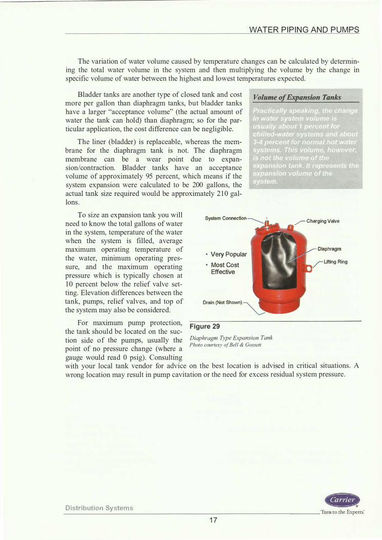
Bladder tanks are another type of closed tank and cost more per gallon than diaphragm tanks, but bladder tanks have a larger "acceptance volume" (the actual amount of water the tank can hold) than diaphragm; so for the particular application, the cost difference can be negligible.
The liner (bladder) is replaceable, whereas the membrane for the diaphragm tank is not. The diaphragm membrane can be a wear point due to expansion/contraction. Bladder tanks have an acceptance volume of approximately 95 percent, which means if the system expansion were calculated to be 200 gallons, the actual tank size required would be approximately 2 1 0 gallons .
To size an expansion tank you will need to know the total gallons of water in the system, temperature of the water when the system is filled, average max1mum operating temperature of the water, minimum operating pressure, and the maximum operating pressure which is typically chosen at 1 0 percent below the relief valve set-ting. Elevation differences between the tank, pumps, relief valves, and top of the system may also be considered .
For maximum pump protection, the tank should be located on the sue-
• Very Popular • Most Cost
Effective
Figure 29 tion side of the pumps, usually the Diaphragm Type Expansion Tank
Photo courtesy of Bell & Gossett point of no pressure change (where a gauge would read 0 psig) . Consulting
Charging Valve
Lifting Ring
with your local tank vendor for advice on the best location is advised in critical situations . A wrong location may result in pump cavitation or the need for excess residual system pressure.
D istri bution Systems --------------------------------- Turn to the Experts:
1 7
-------------·-
WATER P I P I N G AN D P U M PS
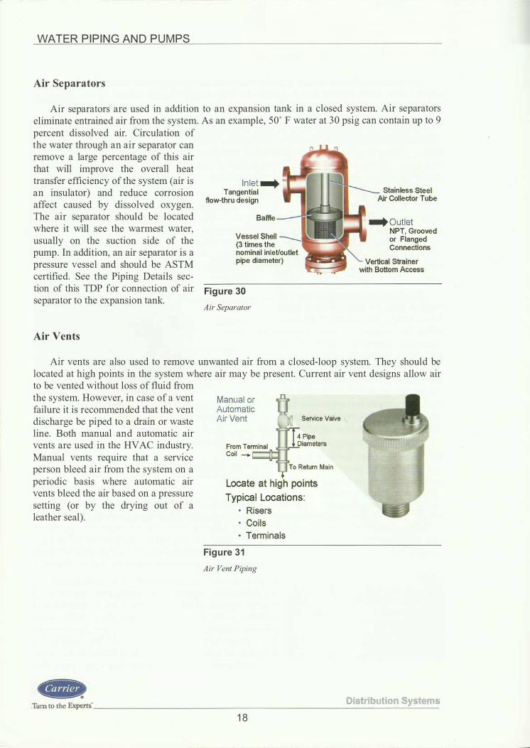
Air Separators
Air separators are used in addition to an expansion tank in a closed system. Air separators eliminate entrained air from the system. As an example, 50° F water at 30 psig can contain up to 9 percent dissolved air. Circulation of the water through an air separator can remove a large percentage of this air that will improve the overall heat transfer efficiency of the system (air is an insulator) and reduce corrosion affect caused by dissolved oxygen. The air separator should be located where it will see the warmest water, usually on the suction side of the pump. In addition, an air separator is a pressure vessel and should be ASTM certified . See the Piping Details sec
In let ... Tangential
flow-thru design
Baffle
Vessel Shell (3 times the nominal inlet/outlet pipe diameter)
tion of this TDP for connection of air Figure 30 separator to the expansion tank.
Air Separator
Air Vents
Stainless Steel Air Collector Tube
... Outlet NPT, Grooved or Flanged Connections
Air vents are also used to remove unwanted air from a closed-loop system. They should be located at high points in the system where air may be present. Current air vent designs allow air to be vented without loss of fluid from the system. However, in case of a vent failure it is recommended that the vent discharge be piped to a drain or waste line. Both manual and automatic air vents are used in the HVAC industry. Manual vents require that a service person bleed air from the system on a periodic basis where automatic air vents bleed the air based on a pressure setting (or by the drying out of a leather seal) .
•+''*
Manual or Automatic Air Vent Service Valve
Locate at high poi nts Typical Locations:
• Risers • Coils • Terminals
Figure 31 Air Vent Piping
D istr ibu t ion Systems Tum to the ExpertS: ____________________________ __:.:__ __
1 8

WATER P I P I N G AN D P U M PS
Thermometers, Gauges, Pete' s Plugs
It is recommended that thermometers, sensors, and gauges be mounted at the inlet and outlet of each major piece of equipment. Major pieces of equipment are chillers, boilers, air handler coils, cooling towers, thermal storage tanks, and pumps .
Pete ' s plugs are small fittings with a rubber seal that can be used to read temperature or pressure with an insertion type thermometer or pressure gauge. They can be used in lieu of fixed location thermometers and gauges and are typically installed at small airhandling units, fan coil units, water source heat pumps, etc . Pressures are used to verify flow through heat exchangers and temperatures are used to measure equipment performance. It is very important that gauges or Pete ' s plugs are located immediately upstream and downstream of each piece of equipment' s connection stub-out but prior to any valves . If mounted after the valve the pressure reading
Locate thermometers and gauges at inlets and outlets of equipment
would include the pressure loss Figure 32
through the valve, this would give an
�I
Pete's Plugs: Temperature and Pressure Ports
� ' ii '
,,
inaccurate reading. Typical Thermometers, Pete 's Plugs, and Gauges Gauges and thermometer photos courtesy of Weiss Instruments, Inc.
Pipe Hangars and Anchors
All piping should be supported with hangers that can withstand the combined weight of pipe, pipe fittings, valves, fluid in the pipe, and the insulation. They must also be capable of keeping the pipe in proper alignment when necessary. Where extreme expansion or contraction exists, roller-type hangers and saddles should be used . The pipe supports must have a smooth, flat bearing surface, free from burrs or other sharp projections that would wear or cut the pipe.
The controlling factor in the spacing of supports for horizontal piping is the deflection of piping due to its own
Recommended Support Spacing for Schedule 40 Pipe Nominal P ipe Size Distance Between Supports
( in . ) (ft) % - 1 % 8 1 y, - 2% 1 0 3 - 3% 1 2 4 - 6 1 4 8 - 1 2 1 6
1 4 - 24 20
weight, weight of the fluid, piping Figure 33 accessories, and the insulation. The
Recommended Support Spacing for Schedule 40 Pipe table lists the recommended support spacing for Schedule 40 steel pipe, using the listed conditions with water as a fluid . The support spacing for copper tubing is given in the next table, which also includes the weight of the tubing filled with water, fittings, accessories and insulation.
Distribut ion Systems --------------------------------- Turn to the Expert& 1 9

WATER P I P I N G AN D P U M PS
In the vertical direction, on a tall building, i . e . 20-stories, the risers might be anchored on the 5th floor and on the 1 5th floor with an expansion device located at the l Oth floor. This arrangement allows the riser to expand in both directions from the 5th and 1 5th floor, resulting in less pipe travel at headers, whether they are located at the top or bottom of the building or in both locations. Smaller buildings, i . e . 5 -stories, risers are anchored but once. Usually this is done near the header, allowing the riser to grow in one direction only, either up or down depending on the header location.
Recommended Support Spacing for Copper Tubing
Tube OD ( in . ) 5/8
7/8 - 1 1 /8 1 3/8 - 2 1 /8 2 5/8 - 5 1 /8 6 1 /8 - 8 1 /8
Figure 34
Distance Between Supports (ft) 6 8
1 0 1 2 1 4
Recommended Support Spacing for Copper Tubes
Horizontal expansion is usually taken up in the many direction changes that occur in a normal layout. When long straight runs occur, proper anchoring is required, as are guides and either
expansion devices or pipe loops to allow proper movement of the pipe as it goes through its temperature range . Detailed presentations on this topic are available in the Carrier System Design Manual, Part 3, and the ASHRAE Handbook-HVAC Systems and Equipment.
Volume Tanks
An important factor in piping design involves having enough volume of chilled water in the piping system to assure stable operation
Rule of thumb for chil led-water systems :
of the chiller. Loop volume is the amount of - 3 gallons per ton of chi l ler for
fluid in the cooler, piping, cooling coils and Suggested volume normal air-conditioning duty
optional storage tank that remains in circula- tank designs tion at all times . If the loop volume is too small, fluctuations in the loading will affect the chiller much more quickly and result in greater compressor cycling with resulting chilled water temperature swings . All chiller manufacturers require a minimum loop vol- F igure 35
- 6 to 1 0 gallons per ton of chi l ler for process duty or low ambient unit operation
ume for proper operation of their chillers to Volume Tank Requirements
prevent rapid changes in water temperature and short cycling of the compressor. In effect, adequate loop volume acts as a "flywheel" so that the chiller does not cycle too quickly. To minimize cycling, the minimum loop volume should be at least three gallons per nominal ton capacity at the design point for normal comfort cooling duty applications . For process and loads that operate under variable flow conditions ; the minimum should be from six to ten gallons per ton. Applications that operate under low ambient temperatures or use brine typically also require six to ten gallons per nominal ton. All recommendations are manufacturer dependent.
Turn to rhe Expert& ____ ____________________ D_is_t_ri_b_u_ti_o_n_S_y_st_e_m_s
20

WATER P I P I N G AN D P U M PS
A method to increase the loop volume is the addition of a volume tank connected to the chilled water system.
For example, suppose a chiller installation with a 200-ton chiller was connected to a system calculated to have a loop volume of 400 gallons. The recommended minimum loop volume would be :
(200 nominal tons) * (3 gallons/nominal ton) = 600 gallons
If the loop volume were 400 gallons and the minimum required loop volume 600 gallons, a volume tank holding a minimum of 200 gallons would be required.
Typical Piping Details at Equipment
Now that we have a basic understanding of piping systems and valves, let ' s take a look at some typical piping details at various pieces of equipment.
Chillers
The installer should mount the valves high, when the piping permits, to allow for removal of piping in order to service the equipment.
Locating thermometers in vertical piping helps avoid damage that could result from mounting them on a horizontal section of pipe.
Locate gauges close to the equipment so that the condenser and cooler pressure drops can be measured and flow verified.
All of these devices must be accessible. The thermometers and gauges must be at an elevation and angle so they can be read.
Supply Return Supply Return +--- Shutoff Valves ---
Thermometer (Typical)'-...
Condenser
Water-Cooled Chiller
Water '--v<�-tl� .... -.IIJI:;;o _ _.J.
Figure 36
Drain) Valve
Typical Water-Cooled Chiller Piping Details, Two-Pass Evaporator And Condenser Shown.
D istri bution S yst ems ------=----------------------------- Turn to the Experts."
2 1

WATER P I P I N G AN D P U M PS
AHU Coil or Fan Coil
For coil piping, where unit discharge conditions are critical, a good recommendation is to use a separate balancing valve so flow can be set and then the valve locked in place. Having a valve on each side of the control valve also allows for control valve servicing.
Mount the valves high and install flanges or unions on the entering and leaving coil connections to allow for removal of piping to service equipment.
Locate Pete ' s Plugs as close to the coil as possible so pressure can be measured and flow verified .
Coil control valves can be 2-position, 2-way modulating, or 3 -way modulating. Multi-row coils should always be piped for counterflow and per the manufacturer' s recommendations . This means the water moves through the coil opposite the direction of airflow. This maximizes heat transfer. For a complete discussion on counterflow, refer to TDP-6 14 , Coils : Direct Expansion, Chilled Water, and Heating.
Pumps
Figure 37
Return -- Shutoff Valve
Valve (2-Position On/Off, 2-Way Modulating or 3-Way Mixing)
Typical Hot or Chilled Water Coil Piping Detail
A concentric reducer is recommended at the pump discharge to allow for smooth flow.
An eccentric reducer is recommended at the pump suction to prevent air pockets in the suction line entering the pump.
The check valve prevents reverse flow through the pump. Shutoff valves are provided to isolate the pump for servicing.
Return (Suction)
Long Radius Elbow
� L...,--1-....-�...u;_�
Figure 38
Minimum of 5 pipe diameters for end suction pumps
Pump Piping Detail
- Shut-Off Valve
- Check Valve - Balancing Valve
or Multi-Purpose Valve
Turn to the Expert& _____ __ _ ____ ____ _ __ _ _ __ _ _ D_i_s_t_ri_b_u_t_io_n_S.::.y_s_te_m_s 22

WATER P I P I N G AN D P U M PS
A separate balancing valve is used so that flow can be set and then the valve locked in place. A single combination valve with a memory stop can be used in lieu of having a shutoff valve and balancing valve on the pump discharge, though it should be mounted downstream of the check valve.
Gauges or Pete ' s plugs should be located as close to the pump as possible so pressure can be measured and flow verified .
A suction diffuser (combination of a strainer and straightening vanes) can also be used at the inlet of the pump. A suction diffuser replaces the valve, strainer, and 90-degree elbow since these items are part of the diffuser. Suction diffusers are used when space limitations do not allow for a minimum of five pipe diameters on the suction side of end-suction pumps . They may also be used to save material and labor cost.
System Piping Arrangements
The figures that accompany the description of each piping arrangement do not show all possible system variations . The diagrams that are shown are to help you understand some of the basic variations of chilled water and condenser water systems.
Parallel and Series Chiller Evaporators
Where chiller capacities greater than can be supplied by a single chiller are required, or where stand-by capability is desired, chillers may be installed in parallel. Units may be of the same or different sizes . Usually, equally sized chillers are utilized to accomplish commonality of parts and maintain simplicity. If unequal sized chillers are used, cooler flow rates must be balanced to ensure proper flow to each chiller. Software is available from the chiller manufacturer that automatically stages multiple chillers of equal or unequal size.
Where a large temperature drop (greater than 1 8° F) is desired, chillers may have to be installed in series. Use of reduced pass configuration may be required to keep waterside pressure drop at an acceptable level.
Para l le l - (Typical ly 1 8 ° F drop or less)
--
54� Series - (Typical ly g reater than 1 8° F drop)
I
Figure 39 Parallel and Series Chiller Piping One-pass evaporators shown.
Distri bution Systems ------------------------------- Turn to the Expert&
23

WATER P I P I N G AN D P U M PS
Single Water-Cooled Chiller Loop
Shown is a single chiller system. It is important to maintain minimum chilled water loop volumes as discussed previously as a single chiller system is often where a loop volume deficiency can exist.
Note that the chilled-water pump pushes water through the chiller then out to the coils . The heat energy from the pump will be cooled in the chiller evaporator before being recirculated to the coils .
Condenser Water Pump
Figure 40
Chilled Water Pump
Single Water-Cooled Chiller System Piping. Two-pass evaporator and condenser shown.
Multiple Water-Cooled Chiller Loop with Dedicated Pumps
In this parallel chiller scheme, there is a dedicated pump for each cooling tower cell and chiller. When chilled water pumps are piped as shown, each chiller is interlocked to its respective pump. The operation of an individual chiller is dependent on the operation of its pumps and tower fan.
Figure 41
Condenser Water Pump
Multiple Water-Cooled Chillers. Dedicated Pumps Two pass evaporator and condensers shown.
Di stributi on Sy stem s Turn to the Experts." _______________________________ _
24

WATER P I P I N G AN D P U M PS
Multiple Water-Cooled Chillers with Manifolded Pumps
When chilled water pumps are manifolded as shown, a condition will exist when one chiller is off and the other is running where there would be flow through the off chiller. To eliminate this problem, a 2-position isolation valve must be added to shutoff flow when the chiller is deenergized . The advantage of this arrangement is that either pump can operate with either chiller. A third pump could even be added as a standby if so desired .
Figure 42
Condenser Water Pumps
Multiple Water-Cooled Chillers, Manifolded Pumps, Two-pass evaporators and condensers shown.
Primary-Secondary Chilled Water System
In a primary-secondary system, each parallel-piped chiller in the primary loop starts/stops with its dedicated pump. Flow for each chiller in the primary loop is maintained by water circulating through the chillers and back through the bypass which acts as a hydraulic decoupler line, or "bridge." Water can flow in either direction within the bridge depending on which flow is greater at any one point in time, the primary flow or the secondary flow.
Production loop (primary)
Hydraulic Decou pier
(Bridge)
Secondary pumping station
- One pump active, the other standby {lead-lag)
- Pumps are VFD-equipped if all coils are 2-way
- Matches secondary flow to coil loads • Hydraulic decoupler maintains constant primary flow
Figure 43 Primary-Secondary Piping System, One-Pass Evaporators Shown.
Alternate Bypass Une minimum chiller flow
Distribut ion Systems ----------------------------------Turn to the Experts."
25

WATER P I P I N G AN D P U M PS
When the primary flow exceeds secondary flow, water flows from discharge to suction in the bridge. When the secondary flow exceeds primary flow, water flows from suction to discharge in the bridge.
Usually, variable-speed drives are used on the secondary pumps to match secondary pump flow to coil load flow demand. These pumps are the large, high-head pumps serving the entire system. When VFDS are used, two-way control valves are used on the coils on the load side of the system. The pump station is often a lead-l�g pump arrangement with only one pump operating at any one point in time . This provides standby and ability to equalize pump operating hours . Check valves are needed for each secondary pump to prevent water circulating backward through the idle secondary pump. Many designers like to place a 3 -way control valve with a bypass on one of the coils to be used as a safety valve for low flow just in case the VFD control fails .
As the two-way coil control valves close off, less water is pumped through the secondary circuit and the secondary loop pressure rises . This would normally mean that the primary pumps would be starved for water if there wasn' t a bypass line. However, the flow not needed by the secondary pumps moves from discharge to suction through the bridge and returns to the primary pumps thereby insuring a constant primary loop flow to the active chiller(s) .
During startup conditions, the coil control valves might all go wide open and the secondary pump will pump more than the design flow provided by the primary loop . If this happens, water flows the opposite way in the bridge line. The extra water not needed by the primary loop passes from bottom to top in the bridge and back to the secondary pump.
The hydraulic decoupler (bridge) line is typically sized for the flow rate required by the largest chiller and should not exceed a pressure drop of 1 . 5 ft wg. It should be a minimum of 3-5 pipe diameters long. For simplicity, the bypass line is often sized the same size as the main supply and return lines, provided it does not exceed the stated criteria for pressure loss .
Primary-Only, Variable-Flow Chilled Water System
Primary-only, variableflow systems take advantage of the ability to modulate the flow through the chiller evaporator and eliminate the need for two sets of pumps (primary and secondary) and instead use a single set of pumps equipped with VFDs .
Variable flow systems have become more popular on primary- secondary systems since there are fewer pumps to buy so floor space is saved, along with first cost.
Figure 44
Control Valve, sized for minimum � chil ler flow
..!..! Bypass �.��----�---�--�� \.... Flow Meter
-Variable Speed Prim ary Pumps
Primary-Only Variable-Flow System. One-Pass Evaporators Shown.
Turn to the Experts: ______ . D istri bution Systems
26

WATER P I P I N G AN D P U M PS
Maximum Capacity of Chillers Two-way control valves are used on the coils and a bridge line is still used and is sized for the minimum flow rate through the largest chiller. A control valve (traditionally controlled by a precision flow meter) is used in the bridge to ensure that the minimum flow rate always returns to the operating chiller(s) .
It is important to understand, however, that there are still limitations on the amount of flow variability. Specifically, the manufacturer ' s recommended chilled water flow range must still be respected as well as the rate of change of flow. As a rule of thumb, the mini
mum evaporator flow rate should not fall below approxi-mately 40 percent to prevent laminar flow. This means that flow may be modulated from 1 00 percent down to 40 percent, resulting in energy savings as the pump energy is related to speed by the cube of the ratio of speeds . The DDC controls must also limit the rate of flow change to adhere to manufacturer' s recommendations . The chiller manufacturer should be contacted for specific chiller application guidelines when designing a primary-only variable flow system. For specific recommendations on variable flow through evaporators , refer to TDP-622, AirCooled Chillers, and TDP-623 , Water-Cooled Chillers .
Since a primary variable system is inherently more complicated than the traditional primarysecondary system, the operating staff must be trained specifically on how to maintain and operate the variable flow arrangement.
If the installation is in a remote area, or a fail-safe design is required, it is probably better to use a traditional primary-secondary system.
If a primary-only, variable flow system is used, an accurate measurement of the return flow rate is essential to stable, reliable operation. This means a precision flow meter is necessary.
Chiller Head Pressure Control
Overnight cooling of the tower and condenser water loop can produce temperatures below 55° F upon start-up. Chillers are designed to operate at condenser water temperatures 55° F and above . Consequently, a bypass is required to maintain an acceptable water temperature so that the chiller will not shut down upon startup .
D istributi on Systems ---------------------------------Turn to the Experts."
27
WATER P I P I N G AN D P U M PS
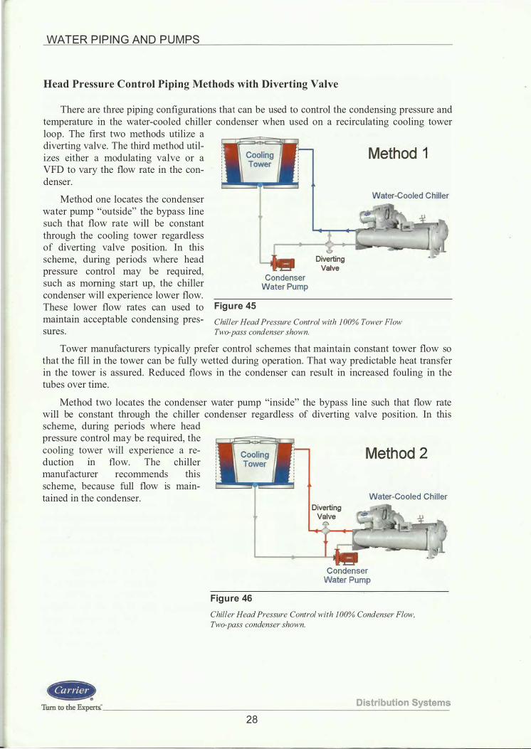
Head Pressure Control Piping Methods with Diverting Valve
There are three piping configurations that can be used to control the condensing pressure and temperature in the water-cooled chiller condenser when used on a recirculating cooling tower loop . The first two methods utilize a diverting valve. The third method utilizes either a modulating valve or a VFD to vary the flow rate in the condenser.
Method one locates the condenser water pump "outside" the bypass line such that flow rate will be constant through the cooling tower regardless of diverting valve position. In this scheme, during periods where head pressure control may be required, such as morning start up, the chiller condenser will experience lower flow. These lower flow rates can used to Figure 45
Condenser
Water Pump
Method 1
Water-Cooled Chiller
maintain acceptable condensing pres- Chiller Head Pressure Control with 100% Tower Flow sures . Two-pass condenser shown.
Tower manufacturers typically prefer control schemes that maintain constant tower flow so that the fill in the tower can be fully wetted during operation. That way predictable heat transfer in the tower is assured. Reduced flows in the condenser can result in increased fouling in the tubes over time.
Method two locates the condenser water pump "inside" the bypass line such that flow rate will be constant through the chiller condenser regardless of diverting valve position. In this scheme, during periods where head pressure control may be required, the cooling tower will experience a re- Method 2 duction m flow. The chiller manufacturer recommends this scheme, because full flow 1s mam-tained in the condenser. Water-Cooled Chiller
Figure 46
Condenser Water Pump
Chiller Head Pressure Control with I 00% Condenser Flow, Two-pass condenser shown.
Turn to thc Expcrts.· ________________________ D_is_t_ri_b_u_ti_o_n_S_::..y_st_e_m_s
28

WATER P I P I N G AN D PUMPS
Head Pressure Control Piping Method with VFD or Modulating Valve
Method three uses a modulating valve to vary the flow in the condenser. The reduced flow rate through the condenser results in less heat transfer and the saturated condensing temperature stabilizes. The flow through the condenser water pump and cooling tower also varies as the system head varies Method 3 due to the change in valve position. The valve will modulate with the variation in water temperature to maintain the desired saturated condensing temperature . In this design, the condenser pump will "ride the curve" because the condenser flow will vary. A VFD can also be used to control the flow directly from a head pressure control signal from the chiller. This method varies the flow through both the condenser and cooling tower and is not as common as the other two methods using diverting valves .
Variable Condenser Flow
Figure 47
Condenser Water Pump
Water-Cooled Chiller
Chiller Head Pressure Control Using VFD or Modulating Valve Two-pass condenser shown.
Pump B asics and Types of Pumps
After the piping system has been laid out, and the total pressure loss, or head, for the pumps is calculated, the selection of pumps can be made. However, a basic understanding of pump terminology is required. In this TDP module we will concentrate on centrifugal pump designs which are the most common types used in comfort air conditioning.
Capacity
Capacity is the amount of liquid that can be pumped, given in terms of gallons per minute (gpm) .
Distri bution System s --------------------------------- Turn to the Expert&
29

WATER P I P I N G AN D P U M PS
Head
Head (hd) is an energy unit that is usually expressed in feet of the liquid being pumped. In a closed system, friction is the only loss or head that the pump has to overcome. The height of water on the suction side of the pump is always exactly equal to the height of the discharge side piping. In open systems this is not true, there is always a difference in head between the suction side and discharge side of
Closed System (evaporator) Suction head is Hs
Discharge head is Hd
• Hs = H d
• Pump must overcome friction loss of the piping circuit only
the pump. In a cooling tower for in- Figure 48 stance, the height between the water Pumping Head Examples level in the basin and the exit from the
rBu 0s
Open System (condenser) • Discharge head = H d
Unbalanced head = H u
• Suction head = (Hd - Hu)
• Pump overcomes friction losses plus Hu
distribution nozzles at the top of the tower represents the unbalanced head that must be overcome by the pump. If the distribution system consists of spray nozzles that require a specific pressure to force water through the nozzles, this pressure must be added to the static head also . The total head of the pump will consist of the following: pipe friction loss, valves including control valves, accessories, equipment such as coolers , condensers coils, air separators , etc . , and any unbalanced head.
If you have a high-rise building, the static head can impose significant pressure on the system components. Example - A 50-story building with 1 2-ft between floors would be 600 ft. high. Since 2 .3 1 ft. equals 1 psi, the pressure on the components at the lowest level would be 600 ft./2 .3 1 ft/psi = 260 psi. The system components at the lowest elevation must be designed for this pressure. In this example, the chiller "waterboxes" would have to be constructed to accommodate 260 psi. If the cooling tower was on the roof, the condenser waterboxes would have to be 300 psi rated as well. If the cooling tower was ground-mounted, the condenser waterbox could be standard construction.
Discharge Head
Discharge head is the head at the pump discharge, made up of the static head at the pump outlet, any positive static pressure in the discharge side of the system, discharge pipe friction loss, and any equipment pressure drop . A pump discharge pressure gauge would indicate total discharge head.
Suction Head
Suction head is the head indicated on a pressure gauge at the pump suction. In a closed-loop system it would be the remaining discharge pressure after subtracting all the piping friction, and the valve and equipment losses . In an open-loop system, suction head includes static head (or lift) , entrance loss and friction head in the suction piping, and any positive pressure existing on the suction side. With a closed-loop system in operation, a pressure gauge at the pump suction would indicate a positive suction head. On an open-loop system the gauge would read negative if the pump was above the fluid source being pumped.
Liquid Horsepower
Liquid horsepower is obtained by the formula, gpm * hd * sp gr -+- 3960 (for standard water sp gr = 1 .0) , where 3960 converts the equation units into horsepower (33 ,000 ft * lb per minute, divided by 8 . 33 lb per gallon) .
Tum to the Experts." D is tr ibution Sy s tem s 30
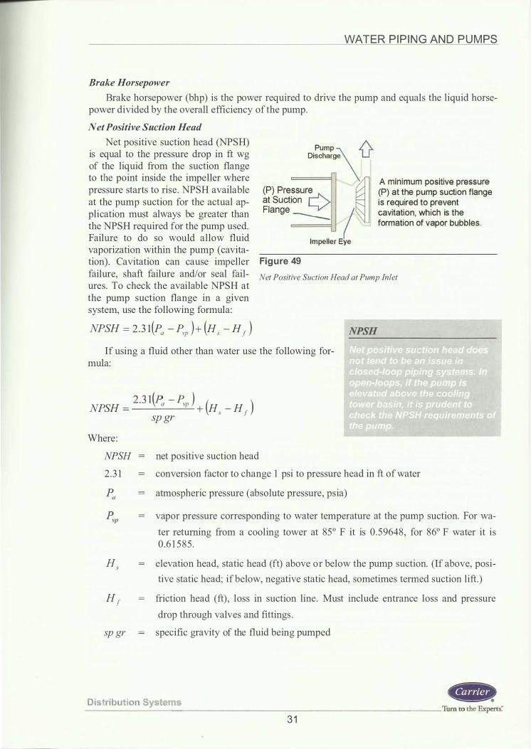
WATER P I P I N G AN D P U M PS
Brake Horsepower
Brake horsepower (bhp) is the power required to drive the pump and equals the liquid horsepower divided by the overall efficiency of the pump.
Net Positive Suction Head
Net positive suction head (NPSH) is equal to the pressure drop in ft wg of the liquid from the suction flange to the point inside the impeller where pressure starts to rise . NPSH available at the pump suction for the actual application must always be greater than the NPSH required for the pump used. Failure to do so would allow fluid vaporization within the pump (cavitation) . Cavitation can cause impeller failure, shaft failure and/or seal failures . To check the available NPSH at the pump suction flange in a given system, use the following formula:
NPSH = 2 .3 1(Pa - Pvp )+ (Hs - H 1 )
Pump 1\ Discharge U
(P) at the pump suction flange is required to prevent
(P) Pressur� at Suction Ly/" Flange --- I cavitation, which is the
formation of vapor bubbles.
Impeller Eye
Figure 49 Net Positive Suction Head at Pump Inlet
NPSH If using a fluid other than water use the following for
mula:
2 . 3 1 {P - P ) NPSH =
\ a vp + (Hs - H )
sp gr 1
Where :
NPSH 2 .3 1
H s
net positive suction head
conversion factor to change 1 psi to pressure head in ft of water
atmospheric pressure (absolute pressure, psia)
vapor pressure corresponding to water temperature at the pump suction. For wa
ter returning from a cooling tower at 85° F it is 0 . 59648 , for 86° F water it is 0 .6 1 5 85 .
elevation head, static head (ft) above or below the pump suction. (If above, posi
tive static head; if below, negative static head, sometimes termed suction lift.)
H 1 friction head (ft) , loss in suction line. Must include entrance loss and pressure
drop through valves and fittings .
sp gr specific gravity of the fluid being pumped
D istri bution System s --------------------------------- Turn to the Experts� 3 1

WATER P I P I N G AN D P U M PS
Figure 50 shows a cross-section of a typical pump. This figure is of a centrifugal inline pump, which gets its name from the straight inlet and discharge water flow. Other centrifugal pump designs will be discussed later Motor in the TDP Module. The figure shows six components of a typical pump : the motor, coupler, bearings , pump shaft, mechanical seal, and the impeller.
The motor is typically an open-drip proof type provided by the pump Figure 50 manufacturer and selected specifically Typical Pump Cross-Section
for the head and flows required.
A coupler mechanism is provided to attach the pump shaft to the motor assembly.
Specifically designed bearings are utilized to provide constant circulation of oil over all bearing surfaces .
The pump shaft serves the purpose of transmitting the motor torque to the impeller.
A mechanical seal is required to prevent water from entering the motor and bearing compartment.
The impeller moves the water through the pump assembly. It is selected specifically for the flow and head required for the application.
Pump Curve
The optimal pump curve for an air-conditioning application is shown here. The very steep curve is not desirable for HV AC duty because it can lead to surging at low flow rates . The very flat curve can be an issue because large flow rate changes occur with small changes in the head.
Important items to understand about pumps are :
1 . Varying the speed - proportionally raises or lowers the head and capacity. The whole head curve shifts up or down.
Very Fia7 -;:==---=:..-- - -
.. _ _ " '
t / ',, '
-o "' "' I
\ \ \ Very Steep_/\ Good
for HVAC
Capacity - gpm -
Figure 51 Pump Curve Examples
- - -
• Characterized by the slope of the pump curve - Flat or steep
• Flat pump curve - Head varies slightly as flow changes - MOTe applicable on closed systems
where variable flow may be used (chilled water circuit)
• Steep pump curve - Head varies significantly as flow
changes - More applicable in open circuits
(tower) where high head with constant flow may exist
2 . Varying the impeller diameter - proportionally raises or lowers the head and capacity. The whole head curve shifts up or down. Increasing the impeller size raises the head and capacity.
3 . Varying the impeller diameter - proportionally varies the capacity.
Tum to the Experti _ __ _ _ _ _ __ ___ _____ ___ _____ D_i_s_t_ ri_b_ u_ t_ i o_ n_S..:.y_ s_ t_e_m_s 32

WATER P I P I N G AN D P U M PS
4. Varying the pitch and number of vanes within the impeller changes the shape of the head capacity curve.
5 . Varying the impeller and vane designs produce variations in head-capacity relationships . Narrow impellers with larger impeller-to-eye diameter ratios develop a larger head. Wide impellers with low diameter ratios are used for low heads and large flows .
Changes in speed and impeller diameters are reflected in pump performance as follows:
rpm1 or impeller dia. 1 = gpm1 = ( head1 J 2 = ( bhp1 J3 rpm2 impeller dia.2 gpm2 head2 bhp2
A given pump operates along its own head-capacity curve. It is a centrifugal device just like a fan. At full capacity flow, the operating point
f falls at the crossing of the pump head-capacity curve and the system � head curve (Point 1 ) . If the pressure drop increases the system curve and
"0 co Q) I Pipe
Friction Head the operating point moves up the
head-capacity curve (Point 2, reduced water flow) . If a greater flow is desired, the pressure drop must be reduced and the operating point would move down the curve (Point
- - - - - - - - - - - - - - - - - ���=i-
3) or the pump could be speeded up, Figure 52
or the impeller size increased which
Capacity - gpm -
would move the head capacity curve Pump and System Curve Intersection
upward (Point 4) . These performance characteristics are just like a fan in a duct system.
If the system head is overestimated and the pump is selected with a high head-capacity curve, unfortunate results may occur. The pump will operate on its head-capacity curve to produce an increased flow at decreased head and increased horsepower demand (Point 1 ). The system head should always be calculated without undue safety factors or as close as practical to the true values to eliminate possible waste of horsepower or possible overloading of pump motor with an unvalved system. If not sized properly, the balancing valve on the pump discharge may have to be throttled or the impeller size decreased to achieve the desired flow. This is especially true when evaluating system head on a system designed with parallel or senes pumps.
;::: I
'C ro Q) I
gJ-r*3-/
I I
"\:Actual bhp _ • \ -
- -- - '\. - - - - -Estimated bhp �
Capacity - gpm -
Figure 53 Overestimating Pump Head
Distribution Sy stems ---------------------------------Turn to the Experts."
33

WATER P I P I N G AN D P U M PS
Parallel Pumps
Parallel pump operation is most common in HV AC and results in multiple gpm capacities against a common head. Example : Two pumps selected at 120 gpm at 50 ft of head will produce 240 gpm at 50 ft of head. Parallel pump application is for systems requiring high capacity with a relatively low head or for systems where a number of small pumps handle the load with one or more pumps shutting down as required. The pumps should have matched characteristics and the motor should have ample power to avoid overloading when operated singly.
Parallel Pumps
Series Pumps
Identical series pumps are used if very high head is required as the flow rate is the same as for each individual pump, but the head is additive . A single higher rpm pump (i . e . 3 500 rpm) could be selected, but the redundancy value of dual pumps would be lost.
Series Pumps
"0 «! (J) r ·
Single Pump Curve
• Two identical pumps in parallel
Resulting gpm doubles
• Plot result to obtain parallel pump curve
Figure 54 Parallel Pump Characteristics
<!= ._§if:!gl� Pump -o Curve «! Ql
r
• Two identical pumps in series • Resulting head doubles • Plot result to obtain series pump curve
Figure 55 Series Pump Characteristics
Parallel ! Pump Curve
gpm
gpm
Distri buti on S yste ms Tum ro me Expetti ____________________________________________________________ �----
34

WATER P I P I N G AN D P U M PS
Variable Speed Pumping
Variable speed pumping is very common. A pump with a VFD operates much like a fan with a VFD. A differential pressure sensor located near the end-of-run in the piping system sends a signal to the VFD to slow down the pump rpm if pressure in the piping is rising, or increase the rpm if the pressure is falling from set point. The pump moves its rpm along the sys-
� tern curve resulting in variations in -o
Constant Speed Pump Curve
flow r��- � :I: Where : bhp = brake horsepower
Energy savings are excellent at reduced flow rates as the bhp follows ;;. the cube ratio of the rpm.
· � • As control valves modu late , the differential pressure across supply and
return lines rises sending signal to VFD to modulate pump speed
• Operating point moves along system curve to new rpm line (points A - B - C)
• According to the pump affinity laws the energy savings is a cubed function of the ratio of the pump speeds
Figure 56 Variable Speed Pumping Characteristics
Selection
Pumps should be selected based on design, size, service, and performance. In terms of performance, a pump should be selected to provide the required flow rate at the design head while
� � �� � � � � � � est possible horsepower. 1so-
Pump Scrics: 1510
Pump catalogs, with pump performance curves, allow the proper pump to be selected. Most pump manufacturers also have software programs that can select the optimal pump for your application. The following is an example of a pump selection from a manufacturer ' s program.
I I ' _11" _J._ ...,,
0%' 16% :OO%z,-.84'/o:r;'!l, ��i!!l Mf .I T T •
16.815' 6% I
125-
15
' i4s28' .. � O%-t= � ..... 1 ' ;es� :1s1'. 18!N.
100-
:S" 1511P �'!'
�--'
. � our-
__.__ llPSHr
' I '
tlPSHr(ft) ""jn�o 10
0
50
25
0 0 400 800 1,200 1,600
Suction Size = 6 .. Discharge Size = S "
Figure 57
Capacity (GPM) MinlmpDia = 9 " Malt Imp Ola = 11 " Cut Oia = 10.875 "
Design Capacity =1000.0 CPM Design Heal! =100.0 Feet Motor Size =40 HP
Typical Centrifugal Pump Selection Screen Capture Courtesy of Bell & Gossett
D i st ributi on Syst ems ------------------------------------ Turn to the Experts�
35

WATER P I P I N G AN D P U M PS
Centrifugal Pump Types
There are several types of centrifugal pumps used in the HVAC industry, such as inline, close-coupled, end suction, vertical split case, and horizontal split case. Which type of pump to use is determined by the flow rate and head requirements, available space, serviceability and cost. The Pump Type Comparison chart below shows the ranking of each type of pump for each category.
l nl ine
Figure 58 Types of Centrifugal Pumps Photos courtesy of Bell & Gossett
Pump Type In L ine
Close-
Coupled
End
S u ction
Vertical
Split Case
Horizontal
S p l it Case
Figure 59
Cost
Least 1
2
3
4
H ig hest 5
Pumv Tvoe Comoarison
Close-Coupled
Flow & Head Space Ease of Capability Required Service
200 g p m @ 55 ft Least 1 Poor 5
2 , 300 gpm @ 400 ft 2 4
4 , 000 g p m @ 500 ft 3 1
9 , 000 gpm @ 400 ft 4 2
40,000 gpm @ 600 ft Most 5 Good 3
Turn to the Experti ________________________ D_i_s_t_ri_b_u_ti_o_n_S--=...y_st_e_m_s
36

WATER P I P I N G AN D P U M PS
Pipe Sizing and Pump Selection Example Steps 1 -7 use a condenser water piping loop as the example system. Step 8 is for sizing the
chilled-water piping loop . Once the piping system with all pipe routing, piping accessories, and equipment has been drawn and the flow rate for each piece of equipment has been determined, it becomes necessary to size the piping. Sizing of the piping will allow the total resistance (head) in the system to be determined so the pumps can be selected.
Step 1: Determine Water Velocity in Piping
Pipe size is limited by velocity based on noise and pipe erosion considerations. Both sound and erosion increase as the velocity increases . The table below gives recommended velocity limits, which are based on experience and are designed to give good balance between pipe size and system life .
Recommended Water Velocities
Service Pump d ischarge Pump suction Dra in l ine Header
Velocity Range (fps) 8 to 1 2
Mains and Riser Branches and Runouts City water
Figure 60 Recommended Water Velocities
4 to 7 4 to 7 4 to 1 5 3 to 1 0 5 to 1 0 3 to 07
The header pipe is close to the pump and carries fluid to the mains and risers . Mains (horizontal) and risers (vertical) distribute the fluid to the various areas of the building where branches and runouts feed the water flow to the air terminals , fan coils, baseboard, etc .
Step 2: Determining Piping Friction Losses
Friction Loss rate for pipe can be found by using Charts 1 , 2 and 3 , which are found in the Appendix. Charts 1 and 2 are normally used for larger size steel pipes, 2:2 Yz-in. , and Chart 3 is usually for smaller pipes, .::::2-in. , where copper tubing is commonly used.
Chart 1 applies to new, smooth, clean, standard weight, steel pipe and can be used to determine the friction loss rate in a closed-loop piping system, such as a chilled water or hot water recirculating system.
Chart 2 applies to standard weight steel pipe that has been subject to scaling. This chart can be used to determine the friction loss rate in an open re-circulating piping system such as a condenser water system with cooling tower.
Chart 3 is used to determine the friction loss in copper tubing, which can be expected to stay clean throughout its normal life. Chilled or hot water systems that use copper piping would be sized with this chart.
Each chart gives the friction loss or head in feet of water per 1 00 ft of straight pipe.
D istribu ti on System s ------------------------------- Tum to the Experti
37
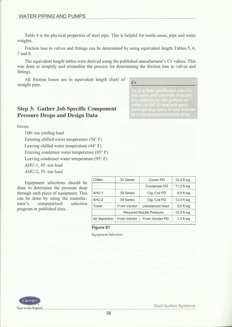
WATER P I P I N G AN D P U M PS
Table 4 is the physical properties of steel pipe. This is helpful for inside areas, pipe and water weights .
Friction loss in valves and fittings can be determined by using equivalent length Tables 5 , 6, 7 and 8 .
The equivalent length tables were derived using the published manufacturer' s Cv values. This was done to simplify and streamline the process for determining the friction loss in valves and fittings .
All friction losses are in equivalent length (feet) of Cv straight pipe.
Step 3: Gather Job Specific Component Pressure Drops and Design Data
Given:
1 00- ton cooling load
Entering chilled water temperature (54° F)
Leaving chilled water temperature ( 44 ° F)
Entering condenser water temperature (85° F)
Leaving condenser water temperature (95 ° F)
AHU- 1 , 45- ton load
AHU-2, 55 - ton load
Chi l ler
A H U - 1
A H U -2
Tower
30 Series
39 Series
39 Series
From Vendor
Cooler PO 1 2 .4 ft wg
Condenser PO 1 1 . 0 ft wg
Clg . Coi l PO 9 . 9 ft wg
Clg . Coi l PO 1 3 .4 ft wg
U n balanced head 6.5 ft wg
Equipment selections should be done to determine the pressure drop through each piece of equipment. This can be done by using the manufacturer' s computerized selection program or published data.
Req u i red Nozzle Pressu re 1 2 . 5 ft wg
Air Separator From Vendor From Vender PO 1 . 3 ft wg
Figure 61 Equipment Selection
Di stribution Syste ms Turn to the Experts." _____________________________ _
38

WATER P I P I N G AN D P U M PS
Step 4: Review the Highest Pressure Drop Circuit and Calculate Water Flows
Cooling tower details usually do not show the exact exit point of the water from the distribution nozzles or the exact water height in the basin. We need to determine the unbalanced head. It doesn't have to be exact; in fact, if you just use the water inlet height minus the outlet height, you will be close enough. For our example, we have a nozzle pressure drop of 1 2 . 5 feet and a height of 6 . 5 feet for a total tower pressure drop of 1 9 ft wg. Condenser Loop
You should contact the cooling tower manufacturer for the pressure drop of the cooling tower selected. Most cooling tower electronic selection programs will show this information. If this information is not available, an approximation of 1 5 ft wg will be close enough in most cases.
The condenser flow rate can normally be obtained from the actual chiller selection. For our example, we will use 3 gpm/ton, which is the ARI standard condenser flow rate.
5'
28'
5'
Figure 62 Sizing the Condenser Water Piping
Water-Cooled Chiller Located on ground floor )),
The chilled water flow rate can be obtained from the actual chiller selection that was based on tons and water �t or it can be calculated based on the following formula :
tons * 1 2,000 Btuh I ton gpm = , or more simply, 11t * 60 min/ hr * 8 . 3 3 /b I gal * sp gr * sp ht
gpm = tons * 24 7 �t
1 00 * 24 7 1 0 = 240 gpm
So we will use 300 gpm for the condenser flow rate and 240 gpm for the chilled water flow in the cooler (evaporator) .
Calculation ofgpm
D ist ribution Systems -----------------------------------------------------------------Tmn w ilie E��t& 39

WATER P I P I N G AN D P U M PS
Step 5: Size the Pipe; Find the Friction Rate/100 ft
First, let ' s size the open-loop system (condenser water system) using Chart 2 to determine the piping friction losses .
Referring to Chart 2 in the Appendix, we find that 300 gpm intersects a 4-in. line size at 8 . 3 ft per second velocity and 1 0 .0 ft of friction loss per 1 00 ft of pipe. Since we also have two pumps that handle 50 percent of the s 8000 flow, we must determine the sooo
line size at the pumps. Refer- •ooo
ring to Chart 2, we find that 1 50 gpm intersects a 3 -in. line 2000
size at 6 .9 ft per second veloc-ity and 9.3 ft of friction loss per 1: 1 00 ft of pipe.
The 300 gpm sections of pipe will be 4-in. size, and the 1 5 0 gpm sections of pipe will be 3 -in. size .
600
400
200
100 80
These sizes are within the 60
recommended water velocity and pressure drop per 1 00 ft Figure 63 recommendations . Sizing the Open-Loop Condenser Water Piping Using Chart 2
6
5
Turn to the Experrs: _______________________ D_is_t_ri_b_u_ti_o_n_S...:y:...s_t_e_m_s
40

WATER P I P I N G AN D P U M PS
Step 6: Find the Longest Circuit Pressure Drop
Next let ' s add up the lengths of straight pipe in each size from the example. We will start at the pump suction and go in the direction of water flow around the loop .
(Note: When two pieces of equipment are piped in parallel, only the circuit with the highest pressure drop should be used in the head calculation.)
3 -in. straight pipe (at pump #2) = 5 + 1 0 + 1 0 + 5 = 30 ft
4-in. straight pipe = 5 + 5 + 5 + 1 0 + 37 + 3 + 5 + 28 + 5 = 1 03 ft
This circuit is represented by C-H
5'
28'
5'
Condenser Loop Find longest circuit pressure drop
by adding all fittings and pipe lengths 37'
-300 gpm
1 0' Water-Cooled Chiller
Located on .....___.. ground floor
..,.,, .. -/' ;;p "'
Next let ' s list the valves and the Figure 64 elbows and any other accessories in the loop in terms of their straight pipe Example Condenser Water Loop
equivalent lengths .
3-in. equivalent lengths (ft)
P ipe (from above) ::::: 30
Std . el ls (qty of 2 at 7.67 ft each) (Table 6) ::::: 1 5
Butterfly Valves (qty of 3 @ 1 1 . 5 1 ft each) (Tab le 5) ::::: 35
Lift Check Valve (qty of 1 @ 1 4 .06 ft) (Tab le 5) ::::: 1 4
Stra iner (qty of 1 at 42 ft) (Table 8) ::::: 42
Tota l ::::: 1 36 ft
4-in. equivalent lengths (ft)
P ipe (from above) ::::: 1 03
Std . e l ls (qty of 7 at 1 0 .07 ft each ) (Table 6 ) ::::: 70
Tees (qty of 2 at 6 . 7 1 ft each ) (Table 5) ::::: 1 4
Butterfly valves (qty of 4 at 1 5 . 1 ft each ) (Table 5) ::::: 30
Contro l valve , butterfly (qty of 1 at 1 6 ft) (Table 8) = _j_Q Total = 233 ft
D i stribut ion Sy stems -----------------------------Turn to the Experts."'
4 1

WATER P I P I N G AN D P U M PS
Step 7: Sum All the Pressure Drops for Pump Selection
Total Friction Loss = Equivalent ft * loss/ 1 00 ft
For 3 -in. pipe, 1 3 6 equiv. ft * 9 . 3 ft / 1 00 Head on Condenser Water Pump (ft)
Frict ion head
For 4-in. pipe, 233 equiv. ft * 1 0 .0 ft / 1 00
Total = 1 2 .65 + 23 . 3 = 3 5 .95 ft wg (round off to 36 ft wg pressure drop)
U n ba lanced head
Pressu re d rop through condenser
Pressu re d rop through nozzles Enclosed is the actual pump curve for the
condenser water pump based on 1 50 gpm each at 66 ft wg of head.
Total head across pump
66 ft
HEAD (Feet}
120-
100-
30-
-60-
40-
20-
0
f-9.5" -�%50'55'1GG%-'s�1,.f .:'2'72.5% fL'I>/0%
'
8.375"
7"-
I--
-f-1.5HP-:m.· '
..... v
--IIP5Hr P_
100 1 50 m QPrt;!apacity !GPMI
Pump Series: 1510
;1!1 �
&5% &D'h
.. . 7.5HP
JUt<u/ HP
+ -1--
300 480
IIPSHI!ftl
To To - e
Suction Size = 2.5 " Oisehat ge Size = 2 "
Mtn lmt> Dia = 7 " Max Imp Oi.l = 9.5 ·• Cut Dia = 8.375 "
Design C-apacity =300.0 GPM (Single Pump =1 50.0)
Design Head =66.0 Feet
Motor Size =5 HP
Figure 66 Example Condenser Water Pump Selection - Parallel Pumps, Single Pump Performance Screen capture courtesy of Bell & Gossett
HEAD (Feet) 100-
Pump Series: 1510 Eff. 1eo -
Figure 65
88
68
20
0 0
' 8.375'
")ower -tiPSHA-
100
Suction Size = 2.5 " Discharge Size = 2 ..
I
� ,�.
200 300 400 500
Capacity (GPM)
Min lmp Oia = 7 " Max Imp Dia = 9.5 " Cut Dia = 8.375 "
Design Capacity =300.0 GPM Design Head =66.0 Feet Motor Size =5 HP
The Power and Eff. curves shown are for the cut dia. impeller.
�· - at
-
-
-
-
600
Example Condenser Water Pump Selection - Parallel Pumps, Performance of Both Pumps Screen capture courtesy ofBell & Gossett
Power(hp)
=
=
=
=
=
36 .0
6 .5
1 1 . 0
1 2 .5
66 .0
Distribution Systems Turn to the Expert& ___________________________________ _
42

WATER P I P I N G AN D PU M PS
Step 8: Size the Chilled Water Loop
The closed-loop system (chilled water system) should be sized using Chart 1 to determine the piping friction losses.
Referring to Chart 1, we find that 240 gpm intersects a 4-in. line size at 6.3 fps velocity and 3 .4 ft of friction loss per 1 00 ft of pipe. Since we also have two pumps that handle 50 percent of the flow, we must determine the line 8000 size at the pumps. Referring to Chart 1 , 6000 ���SijW.����:tS:2;�w�=+� we find that 1 20 gpm intersects a 3 -in. •ooo
line size at 5 . 5 fps velocity and 3 . 5-ft of �:--lllri. 2000 - '>".;;71-.J.�.n.. r.:: friction loss per I 00 ft of pipe.
1000 600 600
400
100 , •. ., • ......,. •• , 80 ���������������· 60
Figure 67 Sizing the Chilled Water Piping Using Chart I
The two air-handling units are piped in parallel so we must use the one that has the highest pressure drop when the piping and AHU pressure drops are summed. Since AHU-2 has the longest length of piping and the coil pressure drop is higher we will use the piping to AHU-2 in our calculation. Referring to Chart 1 , (55 tons * 24 + 1 0 = 1 32 gpm) we find that 1 32 gpm intersects the 3 -in. line size at 6 .0 fps velocity and 4 .0-ft of friction per 1 00 ft of pipe (not shown in the text) . Notice the water flow in this circuit is clockwise with the pump pushing water through the chillers . The longest path of water flow starts at point C, goes through the chiller, up to AHU-2, back down through the air separator, to point N and then through pump number 3 .
Figure 68
Water-Cooled Chi l ler
AHU-1 1 08 gpm
Find longest pressure drop circuit and calculate water flow.
1 5'
20' 2'
D istri bution System s -------------------------------Turn to the Experts�
43
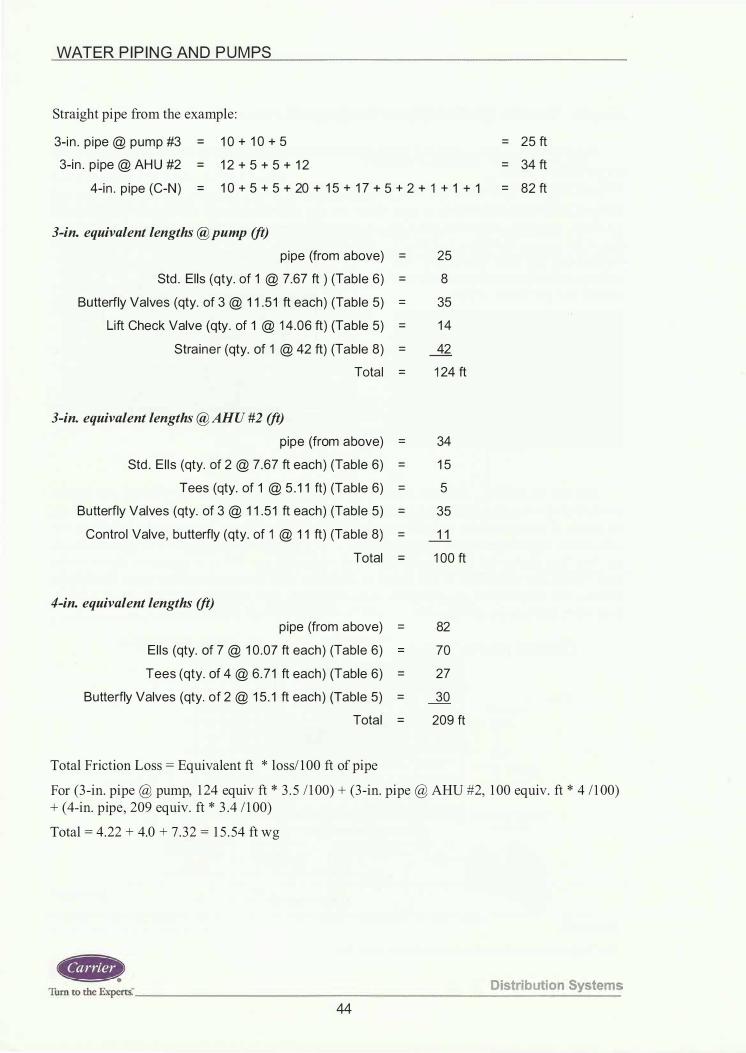
WATER P I P I N G AN D P U M PS
Straight pipe from the example :
3-i n . p ipe @ pump #3 = 1 0 + 1 0 + 5
3-i n . p i pe @ AH U #2 = 1 2 + 5 + 5 + 1 2
4-i n . p ipe (C-N) = 1 0 + 5 + 5 + 20 + 1 5 + 1 7 + 5 + 2 + 1 + 1 + 1
3-in. equivalent lengths @pump (ft)
p ipe (from above) = 25
Std . El ls (qty. of 1 @ 7.67 ft ) (Tab le 6) = 8
Butterfly Valves (qty. of 3 @ 1 1 .5 1 ft each) (Table 5) = 35
Lift Check Valve (qty . of 1 @ 1 4 .06 ft) (Table 5) = 1 4
Stra iner (qty. of 1 @ 42 ft) (Table 8) = 42
Total = 1 24 ft
3-in. equivalent lengths @ AHU #2 (ft)
pipe (from above) = 34
Std . E l ls (qty. of 2 @ 7 .67 ft each ) (Table 6) = 1 5
Tees (qty. of 1 @ 5 . 1 1 ft) (Table 6) = 5
Butterfly Valves (qty. of 3 @ 1 1 .5 1 ft each) (Table 5) = 35
Contro l Valve , butterfly (qty. of 1 @ 1 1 ft) (Table 8) = 1 1
Total = 1 00 ft
4-in. equivalent lengths (ft)
p ipe (from above) = 82
El ls (qty. of 7 @ 1 0 .07 ft each) (Table 6) = 70
Tees (qty. of 4 @ 6 .7 1 ft each) (Table 6) = 27
Butterfly Valves (qty. of 2 @ 1 5 . 1 ft each ) (Table 5) = 30
Tota l = 209 ft
Total Friction Loss = Equivalent ft * loss/ 1 00 ft of pipe
= 25 ft
= 34 ft
= 82 ft
For (3 -in. pipe @ pump, 1 24 equiv ft * 3 . 5 / 1 00) + (3 -in. pipe @ AHU #2, 1 00 equiv. ft * 4 / 1 00) + (4-in. pipe, 209 equiv. ft * 3 .4 / 1 00)
Total = 4 .22 + 4.0 + 7 .32 = 1 5 . 54 ft wg
Turn co the Expcrts: _____________________ D_is_tr_i b_u_t_i o_n_S_;y_s_te_m_s 44

WATER P I P I N G AN D P U M PS
Total Head on Chilled Water Pump (ft wg):
Frict ion Head = 1 5 .5
Pressure d rop th rough Cooler = 1 2 .4
Pressu re d rop through Ai r Separator = 1 . 3
Pressu re d rop through AHU #2 = 1 3 .4
Tota l Head across Pump = 42 .6 ft wg
The chilled water pumps would be based on two pumps of 1 20 gpm each at 42.6-ft of pressure drop and would be selected like the condenser with the pump manufacturer ' s selection software . Actual selections are not shown in this example.
At this point, we can add a safety factor of 10 percent because the actual piping installed may not match the initial design. If the system head is slightly oversized the balancing valve at the pump discharge can be used to impose a false head and balance the flow accordingly. If the system head is oversized to a point where the balancing valve at the pump discharge throttles away too much head then the pump impeller should be "trimmed." When an impeller is trimmed, it is physically reduced in size slightly by machining down the blades . This accomplishes a desired reduction in its capabilities .
We now have all the data to do a system volume check and see if a volume tank is necessary for the chilled water system.
Step 9: Check Evaporator Loop Volume
Required volume rule of thumb for this chiller is approximately 3 gallons per nominal ton. Some chiller loop applications may require higher than 3 gallons per ton, such as process cooling for instance . Some manufacturers do not establish minimum loop volume in terms of gallons per installed ton of chiller. For instance there may be a recommendation that the cooler loop volume be large enough such that it takes at least 4 minutes for the flow to completely move through the entire system. So instead of gallons per ton in that instance, take the gpm flow rate through the chiller and multiply it times 4. That would then be the required minimum loop volume. Always check with the chiller manufacturer for their latest recommendations .
3 gallons per nominal ton * 1 00 nominal tons = 300 gallons
Therefore, the system must have a water volume of 300 gallons .
4-in. pipe, 82-ft * 5 . 5 1 lbs/ft of water (from Table 4 in the appendix) = 452 lbs of water = 54 gallons (water weighs 8 . 3 3 lbs/gal)
3 -in. pipe, 94 ft * 3 .20 lbs/ft of water = 3 0 1 lbs of water = 3 6 gallons
Note : 94 ft of pipe represents all of the 3 -in. pipe, not just the pipe used in the head calculation.
Cooler barrel holds 22 .6 gallons (from manufacturer ' s chiller product catalog)
The AHU coil volume should not be taken into consideration since the coil has a 3 -way valve and could be bypassed.
Distri bution Systems ------------------------------- Tum to the Experts�
45

WATER P I P I N G AN D P U M PS
Total number of gallons in the system = 54 + 36 + 22 .6 = 1 1 2 .6 gallons .
This system needs a volume tank.
300 gallons required - 1 1 2 .6 gallons actual = 1 87 .4 gallon volume tank
Piping System Calculator Tool
Shown here is a picture of a well-known pipe sizing and calculator from a major manufacturer of hydronic pumps and accessories. This tool combines the features of the pipe sizing charts into an easy-to-use prepackaged calculator that many designers and contractors utilize for everyday piping design tasks . The instructions are written right on the calculator.
Some of the functions the calculator perform are :
1 . temperature difference and capacity
2 . friction loss and velocity
3 . pipe length and pressure drop
4. system curve calculation
The same pipe sizes from our example problem for this TDP could have been found on the calculator.
Summary
Figure 69 System Syzer® Calculator Photo courtesy of Bell & Gossett
In this TDP we covered the major topics dealing with water piping. The basic piping systems of closed, open, and once-thru configuration were diagramed.
The four water distribution systems were analyzed and advantages and disadvantages were discussed.
Direct-return and reverse-return options were also covered in detail .
Major piping components, accessories, and typical equipment connection diagrams were presented, along with primary-secondary and variable-primary flow piping designs.
Pump basics and the various types and designs of water pumps were presented, along with a pump comparison summary chart to assist in proper selection.
Finally, a pipe sizing example allowed us to use conventional equivalent length charts and tables to size system piping. An industry hand-held calculator was introduced that could also be utilized instead of the manual charts and tables.
Cf,Mp•) Turn ro the Ex;rti ________________________ D_i_ s_t r_i_b_u_t i_o_n_S_y_ s_t_ e_m_s
46

_______________ --!..W.=..:.A....!..:T:...=E_R P I P I N G AN D P U M PS
Work Session
1 . A chilled water system is a/an _____ loop system.
2 . A condenser water system with a cooling tower is a/an _____ loop system.
3 . Name 4 types o f valves that can b e used for flow control duty?
1 .
2 .
3 .
4 .
4 . What are the 3 types of valves that can be used for shutoff duty?
1 .
2 .
3 .
5 . What i s the price and equivalent pressure drop in feet for a butterfly, globe, gate and ball valve of 6-in. size?
Valve Price Pressure Drop (ft) Butterfly
Globe Gate Ball
6. What determines the need for a volume tank in a closed-loop system?
D istribut ion Systems ------------------------------Turn to the Experts." 47

WATER P I P I N G AN D P U M PS
7 . Sketch a typical piping detail for a pump. Label accessories and note their functions .
8 . Should the pump be pushing or pulling water through the chiller evaporator and condenser?
9 . In a closed-loop system with a flow of 300 gpm, what size chilled water line should be used? What is the water velocity? What is the friction loss in ft of
water I I 00 ft of pipe? ___ _
1 0 . If you have 3 pumps in parallel and the system flow is 400 gpm @ 60ft. of hd, what is the flow through each pump? What is the head at each pump? ____ _
1 1 . Which piping system offers true simultaneous heating and cooling without mixing of the hot and cold water flows? ---------
12 . When should there be concern regarding NPSH?
1 3 . What type of water control valve would be used on the coils in a variable flow chilled-water system? ________ _
14 . What kind of water control valve is used in a conventional constant flow primary-secondary system? ________ _
1 5 . Which piping system required a seasonal "changeover" from cooling to heating and vice versa? ---------
Cf,. 11 h E _ Distribution Systems
ur n to t c xperts. _____________ ___________ _____ _
48

WATER P I P I N G AN D P U M PS
Appendix
References
Bell & Gossett, Morton Grove, IL. http://www.bellgossett.com/
Flexicraft Industries, Chicago, IL. http://www.flexicraft.com/
Weiss Instruments, Inc . , Holtsville, NY. http://www.weissinstruments .com/
Cleaver-Brooks, Milwaukee, WI. http://www.cbboilers .com/
Charts and Tables
Chart 1 - Friction Loss for Closed Pipe
Chart 2 - Friction Loss for Open Piping System Schedule 40 Steel
Chart 3 - Friction Loss for Closed and Open Copper Tubing System
Table 4 - Physical Properties of Steel Pipe
Table 5 - Friction Loss of Valves in Equivalent Length of Straight Pipe (Feet)
Table 6 - Friction Loss of Pipe Fittings in Equivalent Feet of Straight Pipe
Table 7 - Special Fitting Losses in Equivalent Feet of Straight Pipe
Table 8 - Control Valves and Strainer Losses in Equivalent Feet of Straight Pipe
Distribution Systems ------------------------------ Turn to the Experts:
49

WATER P I P I N G AN D P U M PS
20,000
1 0,000 8000 6000
4000
2000
1000 800 600
E 400 0. 0)
� 200 0 't: Q) ..... co 100 � 80
60
40
20
10 8 6
4
2
0.1 0.2
Chart 1 - Friction Loss for Closed-Loop System Schedule 40 Steel
10 20
0.4 0.6 0 .8 1 2 4 6 8 10 20 Friction Loss (Feet of Water / 100 ft)
1 0
8
6
5
4 3 1/2
3
2 1/2
2
1 112
1/2
40 60 80 1 00
c
Q) N Ci5 Q) Q. a:
.,., h E · D istrib ution Systems .urn to t c xpcrts·----------------------------
50
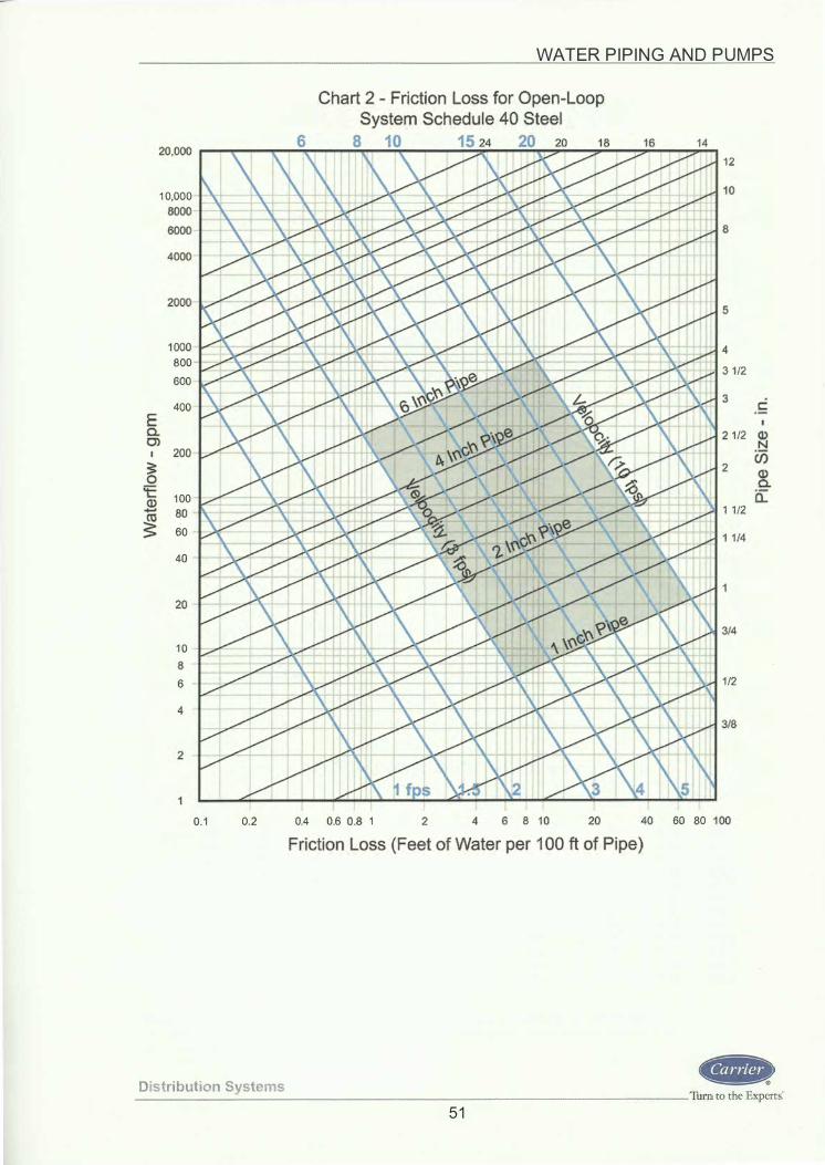
20,000
1 0,000 8000 6000
4000
2000
1 000 800 600
400 E a. O'l
200 � 0
't: 1 00 Q) - 80 � 60
40
20
1 0 8 6
4
2
0. 1 0.2
WATER P I P I N G AN D P U M PS
0.4 0.6 0.8 1 2 4 6 8 1 0 20
12
1 0
8
5
4 3 1/2
3
2 1/2
2
1 1 /2
1 1/4
3/4
1/2
3/8
40 60 80 1 00 Friction Loss (Feet of Water per 1 00 ft of Pipe)
c
� (j) Q) Q. 0.::
Distributi on Systems --------------------------- Turn to the Experti
5 1

WATER P I P I N G AN D P U M PS
4000
2000
1000
800
600
400
E 200 a. en
:!'; 1 00 0 80 'E
60 <1> -
� 40
20
1 0
8
6
4
2
0. 1 0.2
Chart 3 - Friction Loss for Open and Closed Copper Piping System
0.4 0.6 0.8 1
8 1 0 1 5 20
2 4 6 8 10 20
Friction Loss (Feet of Water / 1 00 ft)
6
5
4
3 1/2 3
2 1/2
2
1 1/2 .!: 1 1/4 �
3/4
1/2
3/8
40 60 80 1 00
U5 <1> a. a:
ttip. Tum to the Experrs.· ____________________ D_i _s_tr_i b_u_ti_o_n _S_y_s_te_m_s
52

WATE R P I P I N G AN D P U M PS
TABLE 4, PHYSICAL PROPERTIES OF STEEL PIPE NOM . WT OF PIPE OUTSIDE INS IDE WALL WEIGHT WATER IN OUTSIDE INSIDE S IZE SCHEDULE DIAM DIAM TH ICKNESS OF PIPE PI PE* S URFACE SURFACE (in . ) NO. (in . ) (i n . ) (in.) (lb/ft) (lb/ft) (sq ft/ft) (sq ft/ft) 1 /8 40(S ) 0 .405 0.269 0 . 068 0 .244 0.0246 0 . 1 06 0 . 070 5
80(X) 0.405 0 . 2 1 5 0.095 0 .31 4 0 . 0 1 57 0. 1 06 0 . 0563
1 /4 40(S) 0 . 540 0 .364 0 . 088 0.424 0 .045 1 0 . 1 41 0 . 0955 80(X) 0 . 540 0. 302 0 . 1 1 9 0.535 0 .031 0 0 . 1 4 1 0 . 0794
3/8 40(S ) 0 .675 0.493 0 .09 1 0. 567 0 .0827 0 . 1 77 0 . 1 295 80(X) 0.675 0 .423 0 . 1 26 0 .738 0.0609 0 . 1 77 0 . 1 1 06
1 /2 40(S) 0 . 840 0 .622 0 . 1 09 0 . 850 0 . 1 31 6 0.220 0 . 1 637 80(X) 0 . 840 0.546 0 . 1 47 1 .087 0. 1 01 3 0.220 0 . 1 433
3/4 40(S ) 1 .050 0 .824 0 . 1 1 3 1 . 1 30 0.2301 0 .275 0 .2 1 68 80(X) 1 .050 0 .742 0 . 1 54 1 .473 0 . 1 875 0.275 0 . 1 948
1 40(S) 1 .3 1 5 1 . 049 0 . 1 33 1 .678 0 . 3740 0.344 0.2740 80(X) 1 .3 1 5 0.957 0 . 1 79 2.1 7 1 0 . 3 1 1 2 0.344 0 .2520
1 1 /4 40(S) 1 . 660 1 .3 8 0 0 . 1 40 2 .272 0 .6471 0 .434 0 . 3620 80(X) 1 .660 1 .278 0 . 1 9 1 2 .996 0 . 5553 0 .434 0 . 3356
1 1 /2 40(S) 1 . 90 0 1 .6 1 0 0 . 1 45 2 .71 7 0.8820 0 .497 0 .42 1 3 80(X) 1 .900 1 .500 0 .20 0 3.631 0.7648 0 .497 0 . 3927
2 40(S) 2 .375 2 . 067 0 . 1 54 3.652 1 .452 0.622 0 . 540 1
80(X ) 2.375 1 .939 0 .2 1 8 5 .022 1 .279 0.622 0 . 5074
2 1 /2 40(S) 2.875 2.469 0 .203 5.790 2.072 0 .753 0 .6462 80(X) 2 . 875 2.323 0 .276 7 .660 1 .834 0 .753 0 .6095
3 40(S ) 3.500 3.068 0 .2 1 6 7 . 570 3 .20 0 . 9 1 6 0 . 802 80(X) 3 . 500 2 .900 0 . 300 1 0 .25 2 .86 0 .9 1 6 0 . 76 1
3 1 /2 40(S) 4 .000 3 . 548 0.226 9 . 1 1 0 4 .28 1 .047 0 . 929 80(X) 4 .000 3.364 0 . 3 1 8 1 2 . 5 1 3 .85 1 .047 0.880
4 40(S) 4 . 500 4 . 026 0 .237 1 0 .79 5.51 1 . 1 78 1 . 055 80(X) 4.500 3 . 826 0.337 14. 98 4.98 1 . 1 78 1 . 002
5 40(S) 5.563 5 . 047 0 .258 1 4.62 8.66 1 .456 1 .32 1 80(X) 5.563 4 .8 1 3 0 . 375 20.78 7.87 1 .456 1 .260
6 40(S ) 6 .625 6 .065 0 .280 1 8 . 97 1 2. 5 1 1 .735 1 . 587 80(X) 6 .625 5 .76 1 0 .432 28. 57 1 1 .29 1 .735 1 . 51 0
8 40(S ) 8.625 7.98 1 0 . 322 28.55 21 .6 2 .26 2 .090 80(X) 8 .625 7 .625 0 .500 43.39 1 9.8 2 .26 2 . 006
1 0 40(S) 1 0 .750 1 0 .020 0.365 40 .48 34. 1 2 .8 1 2,62 60(X) 1 0 . 750 9.750 0 . 50 0 54.70 32 .4 2 . 8 1 2 . 55
80 1 0. 750 9.564 0 .593 64.33 3 1 . 1 2 . 8 1 2 . 50 1 2 30(S) 1 2. 750 1 2 .090 0 . 330 43.80 49 .6 3 .34 3. 1 7
40 1 2 .750 1 1 .938 0 .406 53.53 48 . 5 3 .34 3 . 1 3 (X) 1 2 . 750 1 1 .750 0 .500 65 .40 46.9 3 .34 3 . 08 80 1 2 . 750 1 1 .376 0 . 687 88.51 44 .0 3.34 2 . 98
1 4 30(S) 1 4.0 1 3 .250 0 .375 54.60 59.8 3 .67 3 .46 40 1 4 . 0 1 3. 1 25 0 .438 63.37 58 .5 3 .67 3.44 (X) 1 4.0 1 3.000 0.50 0 72 . 1 0 55.8 3 .67 3 .40 80 1 4 .0 1 2.500 0 .750 1 06 . 3 1 5 1 .2 3.67 3 .27
1 6 30(S) 1 6. 0 1 5.250 0 . 375 62 .40 79 . 1 4 . 1 8 3 . 99
40(X) 1 6 . 0 1 5 .000 0 . 50 0 82 .77 76.5 4. 1 8 3 . 93 80 1 6 .0 1 4. 3 1 4 0 .843 1 36.46 69.7 4 . 1 8 3 . 75
1 8 (S) 1 8 .0 1 7.250 0 . 375 70.60 1 00 . 8 4.7 1 4 . 52 (X) 1 8 . 0 1 7.000 0 . 50 0 93.50 98 . 3 4 .7 1 4.45 40 1 8 .0 1 6.874 0 . 562 1 04.75 97.2 4 .7 1 4 .42 80 1 8 .0 1 6 . 1 26 0 .937 1 70.75 88 . 5 4. 7 1 4 . 22
20 20(S ) 20 . 0 1 9 . 250 0 . 37 5 78.60 1 26 .7 5 .24 5 .04 30(X) 20.0 1 9.000 0 . 50 0 1 04 .20 1 22 . 5 5 .24 4 . 97
40 20.0 1 8 . 8 1 4 0 .593 1 22.91 1 20 .4 5 .24 4.93 80 20 . 0 1 7.938 1 .03 1 208.87 1 09 .4 5 .24 4.70
24 20(S ) 24 . 0 23.250 0 . 375 94. 60 1 84.6 6.28 6 . 08 (X) 24 . 0 23.000 0.500 1 25 . 50 1 79 .0 6.28 6 . 03 40 24 . 0 22 . 626 0.687 1 71 . 1 7 1 74.2 6 .28 5 . 92 80 24 . 0 2 1 . 564 1 .2 1 8 296 . 36 1 58 . 2 6.28 5.65
Data from Crane Technical Bul letin No. 4 1 0 -1 991 , reprint pages B-1 6 thru B-1 9 To change "Wt of Water in Pipe (lb/ft)" to "Gallons of Water in Pipe (gallft)," divide values in table by 8 . 34. (S) is designation of standard wall pipe. (X) is desiqnation of extra stronq wall pipe.
TRANS-VERSE AREA (sq in.)
0.0568 0 .0364
0 . 1 04 1 0.07 1 6 0 . 1 91 0 0. 1 40 5
0 .3040 0 .2340
0 .5330 0 .4330
0 . 8640 0.71 90 1 .495 1 .283
2 . 036 1 . 767
3.355 2.953
4 . 788 4 .238
7.393 6 .605 9.89 8. 89
1 2.73 1 1 . 50
20.0 1 1 8 . 1 9
28.99 26 . 07 50.0 45.6
78.9 74.7 7 1 . 8
1 1 5. 0 1 1 1 .9 1 08 .0 1 0 1 .6 1 38.0 1 35 .3 1 33 . 0 1 22 . 7 1 83.0 1 76 . 7 1 60 . 9 234 . 0 227 . 0 224.0 204.2 291 . 0 284 . 0 278 . 0 252 .7 426 . 0 4 1 5.0 402 . 1 365.2
Distri bu ti on S ystems --------------------------------- Turn to the Expert&
53

01 .j:>..
rl 0 "' ft trJ .lj s .. "'•
c iii" -:::!. 0" r:.: ...
(5' :::l en � (j) 3 Ill
Table 5 - Fnctlon Loss of Valves m Equ1va1ent Len �th of straight Pi pe (Feet) Screwed Screwed
90 deg Actuai iD and and 45 &.Ning 90 deg 90 deg 45 deg Jominal Pipe Steel Friction flanged flanged check swing flanged weld angle weld 45 deg weld Plug valve 3 way plug valves �=1 Ball Valve Butterfly lr Tube Size Pipe, Factor, f gate globe valve, check
angle valve angle valve lift check striaght way P=1 , O=O Valve, inches valves valves, P =1 valve, � =1 valve, �=1 p=1 valve P=1 P=1 centered disc
P=1 , o=o p =1 p =1
thru branch 3/8 0.493 0.028 0.33 1 3.97 4. 1 1 2 .05 6. 16 2.26 2.26 2.26 0.74 1 .23 3.70 0. 1 2 -
1/2 0.622 0.027 0 .41 1 7.62 5. 1 8 2.59 7.78 2.85 2.85 2.85 0.93 1 .56 4.67 0. 16 -
314 0.824 0.025 0.55 23.35 6.87 3.43 10. 30 3.78 3.78 3.78 1 .24 2.06 6. 1 8 0.21 -
1 1 .049 0.023 0.70 29.72 8.74 4.37 13. 1 1 4.81 4.81 4.81 1 .57 2.62 7.87 0.26 -
1 1/4 1 .380 0.022 0.92 39. 1 0 1 1 .50 5.75 17 .25 6.33 6.33 6.33 2.07 3.45 10 .35 0.35 -
1 1/2 1 .6 1 0 0.021 1 .07 45.62 13 .42 6 71 20. 1 3 7.38 7.38 7.38 2 .42 4.03 12.08 0.40 -
2 2.067 0.01 9 1 .38 58.57 1 7.23 8. 61 25.84 9.47 9.47 9.47 3. 10 5. 1 7 15.50 0.52 7.75 2 1/2 2 .469 0.01 8 1 .65 69.96 20. 58 1 0.29 30.86 1 1 .32 1 1 .32 1 1 .32 3.70 6. 1 7 1 8.52 0.62 9.26
3 3.068 0.01 8 2.05 86 . 93 25.57 1 2.78 38.35 14.06 14.06 14.06 4.60 7.67 23.01 0.77 1 1 .51 3 1/2 3.548 0.01 8 2.37 1 00.53 29.57 1 4.78 44.35 16.26 1 6.26 16.26 5.32 8.87 26.61 0.89 1 3.31
4 4.026 0.0 1 7 2.68 1 14 .07 33. 55 1 6.78 50.33 1 8.45 1 8.45 1 8.45 6.04 1 0.07 30.20 1 .01 15.10
5 5.047 0.01 6 3.36 143.00 42.06 21 .03 63.09 23. 1 3 23. 1 3 23. 1 3 7 .57 12.62 37. 85 1.26 18.93 6 6.065 0. 01 5 4.04 1 7 1 .84 50.54 25.27 75.81 27.80 27.80 27.80 9. 1 0 1 5. 1 6 45.49 1 .52 22.74 8 7.981 0.014 5 .32 226. 1 3 66.51 33.25 99.76 36.58 36.58 36.58 1 1 .97 1 9.95 59.86 2.00 29.93
1 0 1 0 020 0.014 6.68 283.90 83.50 41 .75 1 25.25 45.93 45.93 45.93 1 5.03 25.05 75. 1 5 2. 51 29.23 1 2 1 1 .938 0.013 7.96 338.24 99.48 49.74 149.23 54.72 54.72 54.72 17.91 29.85 89.54 2.98 34.82 14 1 3. 124 0. 01 3 8.75 371 .85 1 09.37 54.68 164.05 60. 1 5 60. 1 5 60. 1 5 1 9.69 32.81 98.43 3.28 38.28 16 1 5.000 0.0 1 3 1 0.00 425.00 125.00 62.50 1 87.50 68.75 68.75 68.75 22.50 37.50 1 1 2.50 3.75 31.25 1 8 1 6.876 0.01 2 1 1 .25 478. 1 5 140.63 70.32 210.95 77.35 77.35 77.35 25.31 42.19 126.57 4.22 35. 16
20 1 8.814 0.012 1 2.54 533 06 156.78 78.39 235. 1 8 86.23 86. 23 86.23 28.22 47.04 141 . 1 1 4.70 39.20 24 22.628 0.01 2 15.09 641 . 1 3 1 88.57 94.28 282.85 1 03.71 1 03.71 1 03.71 33.94 56.57 169.71 5.66 47. 1 4
NOlES
1 . All valvesas:umed in wide open postion. 2. Row aS3Jmed to be in fully turbulent region of Moody Diagram 3. lhe friction factor f isas:umed cor\Sant over the fully turbulent region . 4. r/ d=bend radiusd ivided by fitting insde d ia meter. 5. Equivalent length values ca lculated from equations in 1 991 Cra ne Technical Paper 410 pagesA27-A29. 6. I) = ratio of dia meter of fitting to d ia meter of pipe 7. 8 = angle of entrance a nd exit to fitting 8. FOr ball valves and butterfly valvesuffi manufacturersCv va lues if ava ilab le , otherwiffi Uffi equivalent length values above for preliminary egimatic
� m :::0 -u -u z G) )> z 0 -u c :s;: -u U>

<J1 <J1
0 v,· .... Table 6 - Friction Loss of Pipe Fittings in Equivalent Feet of Straight Pipe ::::!. C' c: .... (5' ::I (/) '< t/1 .... <D 3 t/1
Nominal Pipe Actuai iD Friction 45 deg std 90 Deg Std Long radius
or Tube Size, Steel Pipe, Factor f elbow elbow 90 deg
inches inches elbow
3/8 0.493 0.028 0 .66 1 .23 0 .66
1 /2 0 .622 0 . 027 0.83 1 . 56 0.83
3/4 0.824 0.025 1 . 1 0 2 . 06 1 . 1 0
1 1 . 049 0.023 1 .40 2 . 62 1 .40
1 1 /4 1 . 380 0.022 1 .84 3.45 1 .84 1 1 /2 1 .6 1 0 0 .02 1 2 . 1 5 4.03 2. 1 5
2 2 . 067 0.01 9 2.76 5. 1 7 2.76
2 1 /2 2 .469 0 . 01 8 3.29 6. 1 7 3.29
3 3.068 0.01 8 4.09 7 . 67 4 .09
3 1 /2 3.548 0.01 8 4 .73 8.87 4.73
4 4.026 0.0 1 7 5.37 1 0. 07 5.37
5 5.047 0.01 6 6 . 73 1 2.62 6.73
6 6.065 0.01 5 8 . 09 1 5. 1 6 8 .09
8 7. 98 1 0 .014 1 0.64 1 9.95 1 0.64
1 0 1 0.020 0.0 1 4 1 3. 36 25.05 1 3 . 36
1 2 1 1 .938 0.0 1 3 1 5. 92 29.85 1 5.92
1 4 1 3. 1 24 0.01 3 1 7.50 32.81 1 7.50
1 6 1 5.000 0 .01 3 20.00 37.50 20.00
1 8 1 6.876 0.01 2 22.50 42. 1 9 22.50
20 1 8.81 4 0 .01 2 25.09 47.04 25.09
24 22.628 0.01 2 30. 1 7 56.57 30. 1 7
NOTES: 1 . Fiow assumed to be in fully turbulent region of Moody Diagram
Std tee
thru flow
0 .82
1 .04
1 .37
1 .75
2 .30 2.68
3.45
4 . 1 2
5. 1 1
5 .91
6 . 7 1
8 .41
1 0. 1 1
1 3. 30
1 6 . 70
1 9. 90
2 1 .87
25.00
28. 1 3
31 . 36
37.71
8 2.The friction factor f is assumed constant over the ful ly turbulent region.
Std tee Reducing tee thru flow
branch flow
1/4 1/2
2.47 1 .09 1 .27
3. 1 1 1 . 38 1 .60 4. 1 2 1 .83 2. 1 2
5.25 2 . 33 2.70
6.90 3 .06 3.55
8 .05 3.57 4. 1 4
1 0.34 4.58 5 .31
1 2.35 5.47 6. 35
1 5.34 6 .80 7.89
1 7.74 7.86 9. 1 2
20. 1 3 8.92 1 0.35
25.24 1 1 . 1 9 1 2.98
30.33 1 3.44 1 5.60
39.91 1 7.69 20.52
50. 1 0 22.21 25.76
59.69 26 .46 30.70
65. 62 29.09 33.75
75 . 00 33.25 38.57
84.38 37 .41 43.39
94. 07 41 .70 48.38
1 1 3. 1 4 50. 1 6 58. 1 8
� .. 4.Equivalent length values calculated from equations in 1 991 Crane Technical Paper 4 1 0 pages A27-A29.
8 , 3. r/d"bend radius divided by fitting inside diameter.
� . � " >",
90 deg weld elbow
r/d=1
-
-
-
-
-
-
3.45
4 . 1 2
5 . 1 1
5 .91
6 .71
8 .41
1 0 . 1 1
1 3. 30
1 6.70
1 9.90
2 1 .87
25.00
28 . 1 3
3 1 .36
37.71 �-� ----·-----
r/d=2
-
-
-
-
-
-
2.07
2.47
3.07
3.55
4.03
5.05
6.07
7.98
1 0.02
1 1 .94
1 3. 1 2 1 5.00
1 6.88
1 8.81
- 22.63
Mitre Bend
45 deg 90 deg
- -
- -
- -
- -
- -
- -
2.58 1 0.34
3 .09 12.35 3 . 84 1 5.34
4 .44 1 7.74
5 . 03 20. 1 3
6 .31 25.24
7 .58 30 . 33 9 .98 39.91
1 2 .53 50. 1 0
1 4.92 59.69
1 6 .41 65.62 1 8.75 75.00
2 1 . 1 0 84.38
23.52 94.07
28.29 1 1 3. 1 4
� _, m ;;o ""U ""U z G) )> z 0 ""U c � ""U (J)

(J1 (j)
eJ 3 8 �
f "'·
0 iii" -::::!. 0" c: ....
o· :::l (/) '< (/) -
(I) 3 (/)
Table 7 Special Fitting Loses in Equivalent Feet of Straight Pipe Nominal Actual Sudden Enlargement,d/D Sudden Contraction ,d/D Pipe Entrance
Pipe Inside D iameter, Diameter, Friction 1 /4 1 /2 3/4 1 /4 1 /2 3/4 Projecting Flush (SE) Projecting
inches i nches Factor f 3/8 0.493 0.028 1 .29 0.83 0.28 0 .69 0.55 0.32 1 . 14 0.73 1 .47
1 /2 0 .622 0.027 1 .69 1 .08 0 .37 0.90 0 .72 0.42 1 .50 0.96 1 .92
3/4 0 .824 0 .025 2 .4 1 1 .55 0.53 1 .29 1 . 03 0.60 2 . 1 4 1 . 37 2.75
1 1 .049 0.023 3.34 2 . 1 4 0 .73 1 .78 1 .43 0.83 2.96 1 . 90 3 .80
1 1 /4 1 .380 0 .022 4 . 59 2 . 94 1 .00 2.45 1 .96 1 . 1 4 4.08 2 .6 1 5.23
1 3/4 1 .6 1 0 0.021 5.62 3.59 1 .22 2.99 2 .40 1 .40 4.98 3 . 1 9 6.39
2 2 . 067 0.0 1 9 7.97 5 . 1 0 1 .74 4.25 3.40 1 . 98 7 .07 4 .53 9.07
2 1 /2 2.469 0.0 1 8 1 0.05 6.43 2 . 1 9 5.36 4.29 2.50 8 . 92 5 . 72 1 1 .43
3 3.068 0 .0 1 8 1 2 .48 7 . 99 2 .72 6.66 5.33 3 . 1 1 1 1 .08 7 . 1 0 1 4.20
3 1 /2 3. 548 O.Q 1 8 14.44 9 .24 3 . 1 4 7 .70 6 . 1 6 3 .59 1 2 . 8 1 8 . 2 1 1 6.43
4 4.026 0 . 0 1 7 1 7.35 1 1 . 1 0 3.78 9.25 7.40 4.32 1 5 .39 9 .87 1 9.74
5 5 . 047 0 .0 1 6 23. 1 0 1 4.79 5.03 1 2 .32 9.86 5.75 20.50 1 3. 1 4 26.29
6 6.065 0.0 1 5 29.61 1 8.95 6 .45 1 5.79 1 2.64 7.37 26.28 1 6.85 33.69
8 7 .981 0 . 0 1 4 4 1 .75 26.72 9.09 22.27 1 7.81 1 0.39 37.05 23.75 47 .5 1
1 0 1 0 .02 0.0 1 4 52.42 33 .55 1 1 .42 27.96 22.37 1 3.05 46.52 29.82 59.64
1 2 1 1 .938 0.0 1 3 67.26 43.05 1 4 .65 35.87 28.70 1 6. 74 59.69 38.26 76.53
14 1 3. 1 24 0.0 1 3 73.94 47.32 1 6 . 1 0 39.44 31 .55 1 8.40 65.62 42 .06 84. 1 3
1 6 1 5 .000 0.0 1 3 84.51 54.09 1 8 .40 45.07 36.06 2 1 .03 75.00 48 .08 96. 1 5
1 8 1 6 .876 0.01 2 1 03.00 65.92 22 .43 54.93 43.95 25.64 9 1 .41 58 .60 1 1 7. 1 9
20 1 8 . 8 1 4 0.0 1 2 1 1 4 .83 73.49 25.01 6 1 .24 48.99 28.58 1 0 1 .91 65 .33 1 30.65
24 22.628 0 .0 1 2 1 38 . 1 1 88.39 30.08 73.66 58.93 34.37 1 22.57 78.57 1 57 . 1 4
Notes: 1 . Equivalent loss values calculated from data in 1 99 1 Crane Technical Paper 4 1 0 pages A27 -A29 and based on sma l ler pipe d iameter. 2. SE = sharp edge 3. Ratio d/D = d iameter of smaller pipe divided by larger p ipe
Pipe Exit
Flush(SE)
1 .47
1 .92
2.75
3.80
5 .23
6.39
9.07
1 1 .43
1 4.20
1 6.43
1 9.74
26.29
33.69
47.51
59.64
76.53
84. 1 3
96 . 1 5
1 1 7. 1 9
1 30.65
1 57. 1 4
Rounded
1 .47
1 .92
2.75
3.80
5 . 23
6.39
9 . 07
1 1 .43
1 4 .20
1 6.43
1 9 .74 26 .29
33.69
47.51
5 9.64
76.53
84. 1 3
96. 1 5
1 1 7 . 1 9
1 30.65
1 57 . 1 4
� --i m ;::o -u -u z G) )> z 0 -u c � -u (J)

CJ1 -....1
c u;· -:::! . CT s::: .... s· ::l en '< 1/1 -(1) 3 1/1
� , 8 .... g. trl • � .. :4 "'·
Table 8 - Conb"ol Valves and Strainer Losses in Equivalent Feet of Straight Pipe
Actual Inside 1\brrinal Friction 1\brrinai Pipe
Diameter, Diameter . Valve Size, Factor f Butter1ly Valve 1•3 Ball Valves1·3 Globe Valves 1•3 Y -Sirainerss inches inches inches 13 = J.cf.S 13 < 1 .d 13 =Lif.S 13 < 1.d 13 =L<f'5 j3 < l.tr RafVJEld
3/8 0.493 - 0.028 - - 0. 1 2 - 1 4 - -1/2 0.622 - 0.027 - - 0.1 6 - 1 8 - -3/4 0.824 - 0.025 - - 0.21 - 23 - -1 1 .049 - 0.023 - - 0.26 - 30 - -
1 1/4 1 .380 - 0.022 - - 0.35 - 39 - -1 3/4 1 .610 - 0.021 - - 0.40 - 46 - -
2 2.067 - 0.019 8 - 0.52 - 59 - 27
2 1/2 2.469 2 O.o1 8 8 9 0.62 2 59 61 28 3 3.068 2 1/2 O.o18 9 1 1 0.77 2 70 72 42
3 1/2 3.548 3 O.o18 12 1 3 0.77 2 86 88 48 4 4.026 3 0.017 1 2 1 6 1 .01 5 114 1 17 60 5 5.047 4 0.016 15 1 9 1 .26 5 143 146 80 6 6.065 4 0.015 1 9 22 1 .52 12 172 1 79 1 10
8 7.981 6 0.014 23 39 2.00 1 1 226 237 150 10 10.020 8 0.014 30 46 2.51 1 2 284 294 1 90
1 2 1 1 .938 1 0 0.01 3 29 35 2.98 1 1 338 346 250 14 1 3. 1 24 12 0.013 35 38 3.28 1 1 372 379 -1 6 15.000 14 0.013 38 42 3.75 1 2 425 431 -18 1 6.876 1 6 0.012 31 44 4.22 1 2 478 484 -20 1 8.814 18 0.012 35 61 4.70 25 533 543 -24 22.628 20 0.012 39 82 5.66 39 641 671 -
Notes: 1 . Equivalent loss values calrulated from data in 1991 Crane Technical Paper 410 pages A2.7-P:2.9. 2. Calrulations based on rrethod of MISI/1St\-S75.01 (R1995)-valve assurred one size smaller than pipe and includes reducer I ses . 3. Values are for estimating only. Check v.ith valve manufacturer for specific details. 4. f3 = diarreter ratio of valve to pipe. f3 =1 valve and pipe sarre diarreter and assurred full bore. 5. Control valves v.ith (3=1 may have reduced ports or shaped discs for irrproved control W"lich v.ill increase loss rmre than full bore values. 6. Strainer dean- no dirt. For dirty strainers rrultiply values by 2.
ScrEMed
5 9
14 20 --
-
--
--
� m ;o -u -u z G) )> z 0 -u c s: -u (/J

WATER P I P I N G AN D P U M PS
Work Session Answers
1 . closed
2 . open
3 . butterfly, globe, angle, plug
4. butterfly, gate, ball
5 .
Valve Price Butterfly 220
Globe 2500 Gate 1 000 Ball 375
Pressure Drop (ft) 22 .74 1 7 1 . 80 4 .04 1 . 52
6 . The amount of water volume in the chilled water system when compared to the manufacturer' s requirement of typically 3 gallons per ton of installed chiller for comfort air conditioning or 6- 1 0 gallons per ton for process cooling.
7 . See Figure 35 , Pump Piping Detail.
8 . Pushing is considered better since the heat of the pump can be picked up in the cooler or condenser as opposed to going into the piping system after the equipment.
9 . 4,-in. 3 - 1 /2-in. is not a common size. Velocity is 8 fps . Approximately 5 ft per 1 00 ft of pipe is the friction loss .
1 0 . 1 3 3 .3 3 gpm; 60 ft of head
1 1 . 4-pipe system
12 . When the NPSH at the pump suction is less that the NPSH required at the pump. This is most likely to occur if the cooling tower is located a distance beneath the condenser water pump.
1 3 . 2-way modulating valve
14 . 3 -way mixing valve
1 5 . 2-pipe
D ist ribution System s Turn to the Expert& _____ _ ___ ______________ _ _ _ �--
58

Prerequis ites :
TDP-1 02 TDP- 1 03 TDP-2 0 1 TD P-30 1
Color Book
796-026 796-027 796-030 796-034
Learn ing Objectives :
After read ing th is modu le , part ic ipants wi ll be able to:
• Compare the three types of p i p i ng systems. Identify the fou r types of water d i stri but ion systems .
Title
• Differentiate between d i rect retu rn and reverse retu rn systems . Identify the various valves and hyd ron ic accessories ava i lab le for use i n p ip ing systems. D iagram typ ica l p ip ing hookups for ch i l l e rs , pumps , and coo l i ng towers .
• S ize the p ip ing for a closed-loop and an open reci rcu lat i ng loop system . Identify t he types of water pumps , the ir features, and t he se lect ion process.
Supplemental Material :
Calculator
I nstructor I nformation
I nstructor Presentation
Bel l & Gossett Title
System Syzer® Calcu lator
Each TDP top ic is s u pported with a n u mber of d ifferent items to meet the specifi c needs of the
user. I nstructor materia l s consist of a CD-ROM d isk that i ncl udes a PowerPoi nfM presentat ion
with conven ient l i n ks to all required support materia ls requ i red for the top ic . Th is a lways i nc ludes: s l ides , presenter notes , text fi l e including work sess ions and work sess ion solutions , qu iz and qu iz answers . Depend i ng u pon the to p ic, the instructor CD may also i hc lude sou n d , v ideo, spreadsheets , forms , or other material req u i red to present a complete class . Self-study o r student materia l consists of a text including work sess ions and work sess ion answers , and may also i nclude forms , worksheets, ca lcu lato rs , etc.

Form No. TDP-502 S u persedes T200-33
Turn to the Experts.
Carrier Corporation Tech n i ca l Tra i n i n g
8 0 0 644-5544 www.tra i n i n g . carr ier . com
/
Cat. No. 796-043 Su perse d e s 791 -033


