Water recharge into the Magnesian limestone aquifer 124 WATER RECHARGE INTO THE MAGNESIAN LIMESTONE AQUIFER D. R. WARDROP 1 , S. SALMON 2 , AND J. K. BLACKBURN 3 1 Lafarge Aggregates Limited, Panshanger Park, Hertford, SG14 2NA. 2 Entec UK Ltd, Northumbria House, Regent Centre, Gosforth, Newcastle-upon-Tyne, NE3 3PX. (AMEC at time of publishing). 3 Lafarge Aggregates Limited, Whitwell, Derbyshire, S80 3LJ. ABSTRACT The study reported in this paper was prompted by the proposed development of a new quarry almost adjacent to an existing Magnesian Limestone quarry in County Durham. Concerns were raised concerning loss of water resource from the Magnesian Limestone aquifer, a potential impact on public water sources down dip and the potential for upwelling of Coal Measures groundwater into the Magnesian Limestone. The quarry operator voluntarily conducted a substantial recharge trial using an instrumented infiltration lagoon and monitoring borehole array. Water balance studies and borehole water level monitoring demonstrated that recharged water quickly travelled through the unsaturated zone and caused an observable and reasonably uniform increase in groundwater levels beneath and around the recharge site. Artificial recharging of water into UK aquifers for storage purposes has been carried on since the 1890’s but using the practice for impact mitigation in rock aquifers is relatively rare. Examples of successful recharging of such aquifers do exist in many other countries. Some informal rock aquifer recharge is known to have been carried out in the UK but such operations do not appear to be thoroughly instrumented or widely reported. Wardrop, D.R., Salmon, S. and Blackburn, J.K. 2012. Water recharge into the Magnesian limestone aquifer. Pp. 124-132 in Hunger, E. and Walton, G. (Eds.) Proceedings of the 16th Extractive Industry Geology Conference, EIG Conferences Ltd, 194pp. e-mail: [email protected]INTRODUCTION The practice of artificially recharging water into UK aquifers has been carried on for many decades, usually for purposes of water supply by utilising aquifers as underground storage reservoirs. Experimental work was carried out in the 1890’s on Hackney Marshes, and the Enfield – Haringey artificial recharge scheme in the Lea valley has been operating since the late 1970’s (O’Shea et al., 1995, Flavin & Joseph, 1983). The Sherwood Sandstone (Environment Agency, 2009), Lincolnshire Limestones and Lower Greensand have also been candidate aquifers for recharge by both borehole and infiltration pit methods (Downing, 1993). Less well known but nonetheless well researched and successfully implemented is the local recharging of sand and gravel aquifers, usually through open pits, most frequently initiated to mitigate or prevent impact on sensitive wetland features due to the dewatering of sand and gravel quarry workings. However, the artificial recharging of waters for impact mitigation purposes in rock aquifers is relatively rare in the UK but examples of successful recharging of hard rock aquifers do exist in many other countries. Some informal rock aquifer recharge is known to have been carried out in the UK but such operations do not appear to be thoroughly instrumented or widely reported. BACKGROUND The behaviour particularly of fissured limestone aquifers in response to either local dewatering of quarries or local recharge is not well understood. This uncertainty was explored during an unpublished study co-ordinated by MIRO in 2003. Data provided in confidence by several quarry operators active in major UK limestone aquifers usually demonstrated, in this study, very unpredictable aquifer behaviour when compared with Darcian groundwater flow theory. The study reported in this paper was prompted by the development of a planning application for a new quarry almost adjacent to Thrislington quarry in County Durham. Concerns were raised by the Environment Agency into matters of loss of resource from the Magnesian Limestone aquifer, a potential impact on public water sources down dip and the potential for allowing upwelling of Coal Measures groundwater from beneath the Magnesian Limestone into that strata sequence. The quarry operator voluntarily conducted a substantial recharge trial using an instrumented infiltration lagoon and monitoring borehole array.
Transcript
Water recharge into the Magnesian limestone aquifer
124
WATER RECHARGE INTO THE MAGNESIAN LIMESTONE AQUIFER
D. R. WARDROP1, S. SALMON
2, AND J. K. BLACKBURN
3
1Lafarge Aggregates Limited, Panshanger Park, Hertford, SG14 2NA.
2Entec UK Ltd, Northumbria House, Regent Centre, Gosforth, Newcastle-upon-Tyne, NE3 3PX. (AMEC at time of publishing).
The study reported in this paper was prompted by the proposed development of a new quarry almost adjacent to anexisting Magnesian Limestone quarry in County Durham. Concerns were raised concerning loss of water resourcefrom the Magnesian Limestone aquifer, a potential impact on public water sources down dip and the potential forupwelling of Coal Measures groundwater into the Magnesian Limestone. The quarry operator voluntarily conducteda substantial recharge trial using an instrumented infiltration lagoon and monitoring borehole array.
Water balance studies and borehole water level monitoring demonstrated that recharged water quickly travelledthrough the unsaturated zone and caused an observable and reasonably uniform increase in groundwater levelsbeneath and around the recharge site.
Artificial recharging of water into UK aquifers for storage purposes has been carried on since the 1890’s but using thepractice for impact mitigation in rock aquifers is relatively rare. Examples of successful recharging of such aquifers doexist in many other countries. Some informal rock aquifer recharge is known to have been carried out in the UK butsuch operations do not appear to be thoroughly instrumented or widely reported.
Wardrop, D.R., Salmon, S. and Blackburn, J.K. 2012. Water recharge into the Magnesian limestone aquifer.Pp. 124-132 in Hunger, E. and Walton, G. (Eds.)
Proceedings of the 16th Extractive Industry Geology Conference, EIG Conferences Ltd, 194pp.
The practice of artificially recharging water into UKaquifers has been carried on for many decades, usuallyfor purposes of water supply by utilising aquifers asunderground storage reservoirs. Experimental work wascarried out in the 1890’s on Hackney Marshes, and theEnfield – Haringey artificial recharge scheme in the Leavalley has been operating since the late 1970’s (O’Sheaet al., 1995, Flavin & Joseph, 1983). The SherwoodSandstone (Environment Agency, 2009), LincolnshireLimestones and Lower Greensand have also beencandidate aquifers for recharge by both borehole andinfiltration pit methods (Downing, 1993).
Less well known but nonetheless well researched andsuccessfully implemented is the local recharging of sandand gravel aquifers, usually through open pits, mostfrequently initiated to mitigate or prevent impact onsensitive wetland features due to the dewatering of sandand gravel quarry workings.
However, the artificial recharging of waters for impactmitigation purposes in rock aquifers is relatively rare inthe UK but examples of successful recharging of hardrock aquifers do exist in many other countries. Someinformal rock aquifer recharge is known to have beencarried out in the UK but such operations do not appearto be thoroughly instrumented or widely reported.
BACKGROUND
The behaviour particularly of fissured limestoneaquifers in response to either local dewatering of quarriesor local recharge is not well understood. This uncertaintywas explored during an unpublished study co-ordinatedby MIRO in 2003. Data provided in confidence by severalquarry operators active in major UK limestone aquifersusually demonstrated, in this study, very unpredictableaquifer behaviour when compared with Darciangroundwater flow theory.
The study reported in this paper was prompted by thedevelopment of a planning application for a new quarryalmost adjacent to Thrislington quarry in County Durham.Concerns were raised by the Environment Agency intomatters of loss of resource from the Magnesian Limestoneaquifer, a potential impact on public water sources downdip and the potential for allowing upwelling of CoalMeasures groundwater from beneath the MagnesianLimestone into that strata sequence. The quarryoperator voluntarily conducted a substantial recharge trialusing an instrumented infiltration lagoon and monitoringborehole array.
GEOLOGY AND HYDROGEOLOGY
Thrislington Quarry lies to the east of Ferryhill inCounty Durham. Quarrying has taken place on the sitesince the early 1950s, and much of the excavatedlimestone is burnt in on-site kilns for a variety ofapplications. The burnt products are tradedinternationally and primarily used for steel fluxes,refractory repair products such as those for blast furnaceliners, and high magnesium fertilisers. Other materialsproduced on site are used for conventional constructionmaterials.
Thrislington Quarry and the proposed new quarry lieon the narrow Magnesian Limestone outcrop ridge thatruns from Nottinghamshire and Derbyshire to CountyDurham. British Geological Survey mapping andMemoirs of the area identify the Permian Lower andMiddle Magnesian Limestone, now referred to as theRaisby and Ford Formations respectively (Smith et al.,1986), overlying the Marl Slate and Permian (nowYellow) Sands. Figure 1 illustrates both the solid geologyand the location of the study site. Lower and MiddleCarboniferous Coal Measures are present at depth andhave been subject to underground mining until recently.Some Glacial Till is present at the surface to the east ofthe A1(M) dual carriageway, including the northern andeastern parts of the Eastern Extension.
Table 1 shows the generalised geological successionfor the area based on the BGS mapping supplemented byprevious site investigations.
The existing quarry extends approximately 2km by1km and works the Raisby Formation down to its contactwith the Marl Slate. In the base of the quarry the MarlSlate is breached in places to assist quarry drainage andto permit local excavation of the underlying YellowSands. The sand excavation (the so-called ‘Sand Hole’) ispartially filled with water, and acts as a sump into whichrunoff and groundwater inflow is drained prior to beingpumped off-site to the west.
Figure 1. Solid geology around Thrislington Quarry.
Table 1. Stratigraphy of the general area around ThrislingtonQuarry.
D.R. Wardrop, S. Salmon and J.K. Blackburn
125
A reasonably extensive groundwater level anddischarge monitoring network is in place at the quarry(Figure 2), with monitoring results at certain locationsextending back to 1994, and in recent years the detailedsite hydrogeology has been thoroughly studied forLafarge by its consultants, Entec UK Ltd. Groundwaterlevels have been recorded for the Magnesian Limestone,Yellow Sands and Coal Measures, from which thehydrographs of Figure 3 demonstrate from limited data
the potential for downward groundwater flow from theMagnesian Limestone into the Yellow Sands and theninto the Coal Measures.
Water monitoring demonstrates that in the vicinity ofThrislington Quarry the Magnesian Limestone waterlevels are typically seven metres above those in theYellow Sands and two metres above in the vicinity of theSand Hole, indicating the potential for downward vertical
Figure 2. Location of monitoring boreholes and recharge pit.
Figure 3. Pre-trial groundwater levels in boreholes.
Water recharge into the Magnesian limestone aquifer
126
flow between the two strata through the intervening MarlSlate. This contrasts with aquifer conditions furthersouth, where upward vertical flow of high sulphatewaters from the Coal Measures into the MagnesianLimestone has been reported (Neymeyer, 2007), possiblyattributable to the cessation of abstractions from the CoalMeasures at Mainsforth Colliery in the early 1970s(Cairney & Frost, 1975, Younger 1993). The cessation ofabstraction from the Coal Measures is also identified inthese studies as the main reason for the long term rise inwater levels identified in the confined limestone to thesouth and east of the quarry.
Groundwater level contours for both the MagnesianLimestone and the Yellow Sands were produced usingApril 2004 data. Figure 4 shows the Magnesian Limestoneplot and confirms that limestone groundwater flow isbroadly west to east beneath the existing quarry, butturning more north-west to south-east beneath theEastern Extension.
The contouring shows high groundwater levelsbeneath the Eastern Extension between 94mAOD in thenorth-west, falling to 91mAOD in the south-east, some 1to 12 metres above the base of the limestone. In themain quarry the water table is generally in the range104mAOD in the west, falling to 92mAOD in the east,where the base of the limestone is approximately 90 to95mAOD and the land surface is generally 130 to140mAOD.
The flow in the Yellow Sands is more north-west tosouth-east, under a more gentle hydraulic gradient.
EASTERN EXTENSION PROPOSALS
The extension on land east of the A1(M) dualcarriageway is planned to be a supplementary quarrymeasuring approximately 1km on it’s North to South axisby 0.75km West to East. This excavation would beconnected to the existing quarry by a tunnel under themotorway, thereby enabling mineral to be transported tothe processing plant.
10km to the south east of the eastern extension lieseveral groundwater public water sources servingHartlepool. The long thin groundwater protection zonesfor these boreholes extend to just beneath the easternextension. Although this overlap only covers a verysmall percentage of the catchments, it was important todemonstrate that the catchments will not be derogated or,should potential derogation be identified, thatappropriate mitigation can be implemented.
The Environment Agency also required assurance thatthe dewatering, needed to enable dry working of thequarry would not lead to the local vertical hydraulicgradient being reversed, with an upward gradient drivingpoor quality Coal Measures water up into the limestoneaquifer and towards the public water sources.
In recognition of these concerns, Lafarge proposedmitigation measures comprising several infiltration pitsdown gradient (south and east) of the eastern extension,such that when dewatering is required from theexcavation the water can be recharged back to thelimestone aquifer. The implementation of structuredmonitoring and mitigation schemes is long established atvarious other locations in the country (Wardrop et al.,2001).
Lafarge is aware of at least two rock quarry complexesin the UK where recharge had been practiced for manyyears, but these older operations had little monitoringinfrastructure and a sparse data record with which tosupport the proposal. The Environment Agency, localwater company, and the County Planning Authorityrequired a high level of confidence that the proposedmitigation scheme would be effective. The principle of aheavily instrumented field trial was therefore developedas the most conclusive method of demonstrating aneffective mitigation strategy, with the major additionalbenefit of providing data with which to design theinfiltration pits and monitoring network of the futureartificial recharge scheme.
The main aim of the field trial was to demonstrate thatrealistically large volumes, akin to those expected to beencountered as a result of dewatering in the EasternExtension (about 1100-1500 m3/d), could be successfullyrecharged to the Magnesian Limestone aquifer. Thisdewatering volume estimate was arrived at from theaverage daily discharge from the main quarry of some1,800 m³/day, and reflects that the main quarry is morethan twice the footprint of the eastern extension andreceives imported water by way of aggregate processingwater pumped from an off site mineshaft.
The trial also aimed to show that vertical headgradients would not be adversely affected by theproposed recharge scheme.
The trial and the monitoring protocols were agreed inadvance with the Environment Agency, and the exerciseembraced a range of recharge rates and varyinggroundwater conditions.
THE RECHARGE TRIAL
The essence of the trial was to construct an infiltrationpit within the permitted area of the existing quarry westof the A1 dual carriageway, create a network ofmonitoring boreholes in appropriate locations around thepit (inset on Figure 2), and then pump water into thefeature at various rates over a suitable period of timewhilst monitoring the behaviour of the pit and theaquifer.
After satisfying planning conditions in respect ofarchaeology and soil stripping, a rectangular excavationmeasuring 100m long by 50m wide by 10m deep wasconstructed some 100m to the south of the uppersouthern face of the existing quarry, immediately to theeast of Thrislington Plantation (NZ 3215 3258). This testsite will soon be lost as the quarry face is advancedsouthwards.
The feature was formed by conventional drill and blast
techniques, with walls left as close to vertical as was safe,and in a condition that would be fully representative ofthe mitigation features proposed for the eventual easternextension.
The floor of the excavation, just as in a normal quarry,had been trafficked by wheeled dump trucks and thuswas likely to demonstrate substantially reducedinfiltration capability due to the formation of a layer ofcomminuted compacted limestone over the naturallyfractured rock. For this reason, the floor of the rechargefeature was ripped by a bulldozer once there was nofurther requirement for dump truck traffic. Cruciallythough, it must be recognised that the floor of a rechargefeature need not be the only, or indeed the main,infiltration surface available for recharge. The near-vertical sidewalls of the excavations are inherently lessclogged and less prone to future blinding by siltation,and presented a potential infiltration area almost as greatas the excavation floor itself.
Seven observation boreholes comprising 50mmgeowrapped standpipes in 100mm diameter drilled holessurrounded the feature, shown on Figure 2. Theboreholes were positioned 10m to 25m from the pit edge,representing radii of 41m to 115m from the point ofdischarge, and measured water levels only in theMagnesian Limestone. The boreholes were positioned soas to enable groundwater level contours to beconstructed beneath the entire extent of the trial site,though with an emphasis towards the down-gradientdirection where the recharged water was anticipated totravel. The authors wished to demonstrate thatgroundwater levels in the limestone responded to theinfiltration in the vicinity of the site and confirm that theinfiltration was reaching the water table. An indication ofwater level ‘mounding’ and the preferential direction offlow would give some confidence that monitored waterlevels could be used to trigger progressive mitigationmeasures in future.
Twelve of the pre-existing boreholes in the quarry andaround the perimeter of the proposed eastern extension(Figure 2) were selected to monitor the trial, including anumber of Yellow Sands boreholes. The majority of theborehole water levels were monitored by data-loggers,with weekly manual check dips, the latter consistentlytracking the electronic data.
Background monitoring records exist from 1999 for thequarry network while Environment Agency records pre-date 1994. A very reliable dataset exists against which tojudge the efficacy of the recharge activity.
An off site Environment Agency “Reference Borehole”was identified that could confidently be expected, not toinfluenced by the trial pumping, such that meteorologicaland aquifer behaviour away from the site could beidentified.
Supporting data comprised:
1) Daily rainfall for Lafarge’s Thrislington rain gauge;
Water recharge into the Magnesian limestone aquifer
128
A sump was excavated in the floor of the operatingquarry to the north of Thrislington Plantation (figure 4) inorder to provide water for the trial. The location wasbelieved to be substantially unaffected by both theroutine quarry dewatering carried out in the ‘Sand Hole’,located in the south west corner of the quarry, and fromrisk of recharge from the infiltration feature. The sumpused a diesel pump feeding 770m of pipeline rising 41mto a metered discharge point at the infiltration pit. A50mm PVC tube was installed on one corner of theinfiltration pit for manual water level monitoringpurposes.
PRE – TRIAL
A ‘trial test’ undertaken in November and December2007, involving volumes of recharge water up to1,000m3/d. The purposes of this preliminary test were toconfirm the feasibility of the recharge approach; toestablish the logistics and monitoring requirements of themain test; and check the pump, pipework andmonitoring infrastructure in order to establish asustainable pumping rate in balance with the supplycapability of the sump.
The informal test started on 20th November 2007, anddischarges into the infiltration pit continued for mostworking days until 11th December, with an additionalisolated discharge on 17th December. A maximumdischarge of 990m3/d was achieved on 3rd December,whilst over the days of operation the average dischargewas 485m3/d.
During this period all the water was seen to infiltratevery rapidly into the floor of the recharge feature. At thetime, after a substantial period of dry weather, the watertable in the Magnesian Limestone was generally 30 to35m below the floor of the feature and was clearlyidentified in all of the monitoring boreholes.
All 7 monitoring boreholes successfully identified arise in water table attributable to recharge pumping witha lag time of only an hour or two between start ofrecharge and a rise in water table being identified. Thetypical rise was in the order of 5 to 7m. A majorcomponent of the recharge was identified in the downdip monitoring boreholes which is intuitivelyunsurprising but nevertheless satisfactory outcome in thecircumstances.
On cessation of pumping the induced rise in thegroundwater table decayed over a period of 3 to 4 dayswith most of the recovery occurring within 24 hours.
THE MAIN TRIAL
The main trial commenced on 14th January 2008, withdischarges occurring on the majority of working daysuntil 29th February 2008. Dry weather constrained theavailable water at times, with daily rates varying from0 to 2120m3/d. During the days of operation the averagedischarge was 900m3/d. The maximum weekly dischargerates were around 1000m3/d initially, with increases eachweek to a maximum of 2120m3/d in early February 2008.Thereafter, maximum weekly rates were around1500m3/d.
Effectively a stepped recharge test has been carried outalong the lines of the conventional stepped discharge testfor borehole testing and the results were consideredamenable to similar analysis.
RESULTS
i.Water Balance
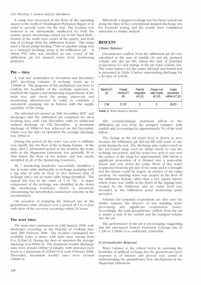
Groundwater outflow from the infiltration pit (E) wascalculated as the sum of rainfall (A) and the pumpedvolume into the pit (B), minus the sum of potentialevaporation (C) and change in the pit water volume (D).The water balance for the entire informal and formal testis presented in Table 2 below representing discharge forc.50 days of activity.
The overwhelmingly dominant inflow to theinfiltration pit was from the pumped volumes, withrainfall only accounting for approximately 5% of the totalinflow.
The change in the pit water level is shown as zerobecause the infiltration pit did not fill with water at anypoint during the test. The discharge pipe outlet rested onthe excavated ramp used by dump trucks to exit therecharge excavation, and the water was seen to run overthe surface of the ramp for approximately 25m before asignificant proportion of it drained into a noticeablefissure part way down the ramp. Much of this waterreappeared from the pit side of the ramp and it is thoughtthat the fissure could be largely an artefact of the rampcreation. No standing water was created in the floor ofthe infiltration feature, other than a few square metreswhere water was visible in the bases of the ripping linescreated by the bulldozer, and no water level wasrecorded in the infiltration pond monitoring pointprovided.
Volumes for potential evaporation are also zero forsimilar reasons, the absence of any standing waterpreventing any significant evaporation losses.Accordingly, the total groundwater outflow from the pitis simply a sum of the rainfall and the pumped volumeinto the pit.
The performance of the pit is encouraging, suggestingthat the anticipated Eastern Extension recharge rate of1,100 to 1,500m3/d is confidently achievable.
ii. Groundwater Response
Water balance is the critical factor in assessing thefeasibility of artificial recharge but the groundwater levelresponse is of interest and proved very useful inunderstanding the groundwater flow mechanisms in theMagnesian Limestone.
Table 2. Water Balance Results
D.R. Wardrop, S. Salmon and J.K. Blackburn
129
Pre-trial Groundwater Levels
Water levels within the Magnesian Limestonedemonstrate a general north-west to south-east hydraulicgradient, ranging from about 98mAOD in the west (BH6A) to 74mAOD in the east (Lizards Farm) shown onFigure 2. The water levels are some 30m beneath the pitat about 95 to 100mAOD. In the western limestone outcropareas, the water level response to natural recharge isquite marked, with water level changes of 5m notuncommon. In contrast, water levels recorded in boreholesfurther to the east are generally much flatter and lessresponsive, as they monitor levels where the MagnesianLimestone is covered by drift. Seasonal fluctuationswithin these boreholes are typically up to one metre.
Groundwater levels within the Yellow Sands aremonitored within the existing site and the EasternExtension. They are generally 5-10m below those in theMagnesian Limestone, implying the potential fordownward vertical flow, and they respond more slowlyto recharge events. That they respond to recharge at allsuggests that the Marl Slate Formation, which liesbetween the Yellow Sands and the Magnesian Limestone,behaves more like an aquitard than an aquiclude.
Groundwater levels within the Coal Measures aremonitored at fewer locations. In general, levels withinthe Coal Measures appear to be below those in theYellow Sands and Magnesian Limestone, again implyingdownward vertical groundwater flow.
Trial Groundwater Levels
Responses to the varying discharges into theinfiltration pit were clearly visible in all the hydrographsfor the boreholes surrounding the pit, with a typical netrise of around 7m. The nature of the response reflectedthe nature of the discharge regime. For example,including periods when shortage of sump water meantdischarges into the pit were intermittent, the limestonegroundwater levels were very variable and displayedrapidly responding peaks. That the effect on water levelswas so obvious, repeated and widespread is encouragingin terms of the predicted success of a future artificialrecharge regime.
One borehole, for instance, at the commencement ofthe main trial demonstrated 90% of its water level risewithin the first 12 hours with full rise at 20 hours. Atcessation both boreholes 4 and 5 demonstrated 90% ofthe recovery to natural water levels at 24 hours with fullrecovery at about 3 days. The shape of the recoverycurve is very similar, in reverse, to that of a boreholepump test recovery curve in a Darcian aquifer.
Monitoring boreholes to the north and north east ofthe infiltration site display a slightly less spiky and slightlysubdued response that is entirely consistent with the flowdirection analysis presented later.
Observed water level responses are sufficiently similarto theoretical behaviour to suggest Darcian flow and theeffect of fissures, that in karstic aquifers elsewhere haveresulted in water completely bypassing monitoringnetworks, must be only local. The authors interpretationis that the aquifer benefits from a sufficiently wellconnected fracture network as to approximate Darcianbehaviour at the study scale.
INTERPRETATION
The shape of the induced mound resulting from theartificial recharge needs to be borne in mind whenlocating future infiltration pits. For example, if aninfiltration pit is positioned too close to existingworkings, the rapid rise in water levels could result insignificant recycling of water between the pit and theworkings. This does not mean that the operation fails tomeet its objectives with respect to water resourceretention, but it does introduce inefficiencies andincreased pumping costs. This potential difficulty can beavoided by locating the infiltration pit further away fromthe workings, and/or by employing more than one pit.
The time lag between recharge and full water level risewas only a day or so, despite the underlying limestoneunsaturated zone being 30-35m thick. This rapid traveltime implies the dominance of small scale fissure flow inthe unsaturated zone. All the test boreholes responded tothe discharge at approximately the same rate and time,despite the discharge originating from a point source.This suggests that the infiltrating water moved rapidlylaterally as well as vertically, most probably alongbedding planes and other discontinuities within theunsaturated zone.
Superimposed on the daily limestone water levelfluctuations was a longer-term variation. Averagegroundwater levels increased until the end of January2008, and then showed a gradual decline. The boreholesdistant from the pit are not thought to have beenimpacted by the trial and show a similar long-termvariation, strongly suggesting that the variation reflectedthe natural seasonal groundwater level trend.
Boreholes within the Yellow Sands were responding tothe recharge test but in a relatively muted fashion, with arise of no more than one metre. The differing responsebetween the Magnesian Limestone and the Yellow Sandsresulted in downward vertical gradients between theaquifers increasing during the periods of active recharge.This implies less potential for upward flow ofcontaminated waters from the Coal Measures, and is avery important benefit of the recharge scheme.
Post-trial Groundwater Levels
The recharge test finished at the end of February 2008,but monitoring continued, to observe groundwater levelrecovery. In general, groundwater levels within theMagnesian Limestone in the following weeks fell to levelsslightly higher than those seen in the pre-trial period, dueto continued natural recharge.
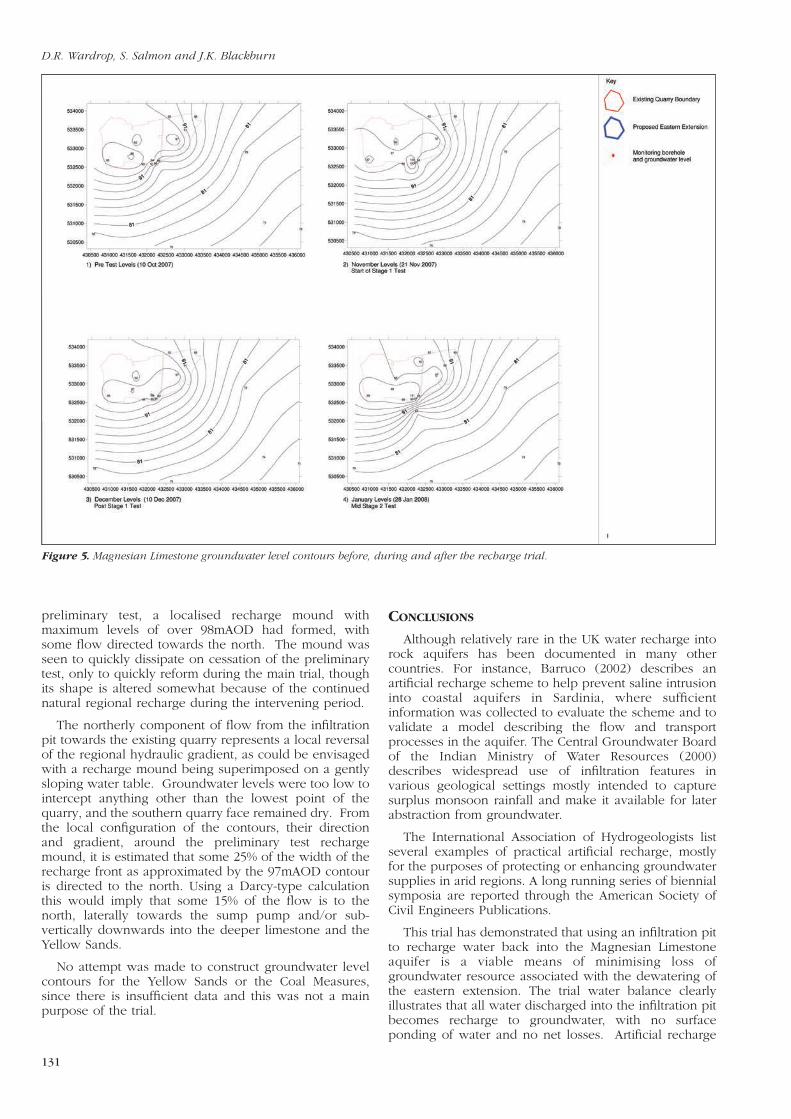
Groundwater Level Contours
Several limestone groundwater level contour plotswere produced as a means of evaluating the impact ofthe recharge test and four of these plots are presented inFigure 5.
All four plots show that the regional groundwatergradient in the Magnesian Limestone is to the south east,but in other respects there are some noticeabledifferences. Before the trial started, groundwater levelsacross the recharge site were relatively uniform at about92mAOD. Just after the commencement of the
Water recharge into the Magnesian limestone aquifer
130
preliminary test, a localised recharge mound withmaximum levels of over 98mAOD had formed, withsome flow directed towards the north. The mound wasseen to quickly dissipate on cessation of the preliminarytest, only to quickly reform during the main trial, thoughits shape is altered somewhat because of the continuednatural regional recharge during the intervening period.
The northerly component of flow from the infiltrationpit towards the existing quarry represents a local reversalof the regional hydraulic gradient, as could be envisagedwith a recharge mound being superimposed on a gentlysloping water table. Groundwater levels were too low tointercept anything other than the lowest point of thequarry, and the southern quarry face remained dry. Fromthe local configuration of the contours, their directionand gradient, around the preliminary test rechargemound, it is estimated that some 25% of the width of therecharge front as approximated by the 97mAOD contouris directed to the north. Using a Darcy-type calculationthis would imply that some 15% of the flow is to thenorth, laterally towards the sump pump and/or sub-vertically downwards into the deeper limestone and theYellow Sands.
No attempt was made to construct groundwater levelcontours for the Yellow Sands or the Coal Measures,since there is insufficient data and this was not a mainpurpose of the trial.
Figure 5. Magnesian Limestone groundwater level contours before, during and after the recharge trial.
CONCLUSIONS
Although relatively rare in the UK water recharge intorock aquifers has been documented in many othercountries. For instance, Barruco (2002) describes anartificial recharge scheme to help prevent saline intrusioninto coastal aquifers in Sardinia, where sufficientinformation was collected to evaluate the scheme and tovalidate a model describing the flow and transportprocesses in the aquifer. The Central Groundwater Boardof the Indian Ministry of Water Resources (2000)describes widespread use of infiltration features invarious geological settings mostly intended to capturesurplus monsoon rainfall and make it available for laterabstraction from groundwater.
The International Association of Hydrogeologists listseveral examples of practical artificial recharge, mostlyfor the purposes of protecting or enhancing groundwatersupplies in arid regions. A long running series of biennialsymposia are reported through the American Society ofCivil Engineers Publications.
This trial has demonstrated that using an infiltration pitto recharge water back into the Magnesian Limestoneaquifer is a viable means of minimising loss ofgroundwater resource associated with the dewatering ofthe eastern extension. The trial water balance clearlyillustrates that all water discharged into the infiltration pitbecomes recharge to groundwater, with no surfaceponding of water and no net losses. Artificial recharge
D.R. Wardrop, S. Salmon and J.K. Blackburn
131
increased downward vertical hydraulic gradients in theaquifer, minimising the risk of induced upward flows ofcontaminated groundwater from the Coal Measures. Thepredominant lateral groundwater flow direction of therecharged water was to the south east, and this isexpected to be even more evident in the easternextension, thus providing effective resource protection tothe catchment zones of the Hartlepool Public WaterSupply boreholes.
The trial has also indicated that simple boreholes ofappropriate design in this setting are an effective methodof monitoring water level response to artificial rechargein this fissured aquifer. A marked response to therecharge was observed at all nearby monitoringboreholes, suggesting that monitored water levels couldbe used to control a future recharge operation within amonitoring and mitigation scheme.
Apart from confirming that the recharge schemeproposals are essentially sound, the trial helped addresssome of the practicalities of the larger recharge operation.For example, the hydraulic conductivity of the limestonesurface was higher than anticipated, and sedimentbinding was not a particular problem, so any futureinfiltration pits can be much smaller than the pit usedduring the trial. The local reversal of the hydraulicgradient was shown to occur in the vicinity of theinfiltration pit, with some flow heading back towards thequarry, and to avoid unnecessary recirculation of waterthe future infiltration pit(s) will need to be located furtherfrom the quarry void.
The test has also revealed information about thedominant groundwater flow mechanisms in the aquifer,including rapid transmission times through theunsaturated zone, the behaviour of the Marl Slate as anaquitard rather than aquiclude, and definite hydrauliccontinuity between the Magnesian Limestone and theYellow Sands.
The conclusions therefore are that the rechargeexperiment was highly successful. As a result, theEnvironment Agency felt able to withdraw itshydrogeological concerns regarding the development,leading to the proposed quarry extension receiving aresolution to grant planning permission. It must beemphasised that the results of this trial and anyconclusions here presented are specific to this part of theMagnesian Limestone aquifer. Any implications drawnfor other areas and particularly other hard rock aquifersmust be treated with caution, and reliance should insteadbe placed on the results of field trials.
ACKNOWLEDGEMENTS
The authors are grateful to Gareth Burdell, NeilOgden, Neil Thomas, and Lisa Parkin for their invaluableassistance in the setting up and running of the trial, andto Annie Butterfield for the preparation of the originaltypescript.
REFERENCES
Barruco, G. 2002. Seawater Intrusion into the coastal aquifers of Italy,Coastal Aquifer Intrusion Technology: Mediterranean Countries.
Cairney, T. and Frost, R. C. 1975. A case study of mine waterdeterioration, Mainsforth Coliery, County Durham. Journal. ofHydrogeology, 25, Pp.275-93.
Central Groundwater Board. 2000. Guide on Artificial Recharge toGroundwater. Ministry of Water Resources, New Delhi.
Downing, R. A. 1993. Groundwater resources, their development andmanagement in the UK: an historical perspective. Quarterly Journalof Engineering Geology, Vol. 26, No. 4, Pp.335 – 358.
Environment Agency. 2009. East Midlands and Yorkshire SherwoodSandstone Groundwater Modelling Study, Final Report.
Flavin, R. J., and Joseph, J. B. 1983. The hydrogeology of the Lee Valleyand some effects of artificial recharge. Quarterly Journal ofEngineering Geology, Vol 16, No. 1, Pp 65 – 82.
Neymeyer, A., Williams, R. L. and Younger, P. L. 2007. Migration ofpolluted mine water in a public supply aquifer. Quarterly Journal ofEngineering Geology and Hydrogeology, Vol. 40, Part 1 Pp 75 – 84.
O’Shea M. J., Baxter K. M. and Charalambous, A. N. 1995. Thehydrogeology of the Enfield-Haringey artificial recharge scheme,north London. Quarterly Journal of Engineering Geology andHydrogeology, Vol. 28, Part 2, Pp. S115-S129.
Smith, D.B., Harwood, G.M., Pattison, J. and Pettigrew, T.H. 1986. Arevised nomenclature for Upper Permian strata in eastern England.In The English Zechstein and Related Topics (eds G.M. Harwood andD.B. Smith), Geological Society of London, Special PublicationNo. 22, Pp.9–17.
Wardrop, D. R., Leake, C. C. and Abra, J. 2001. Practical techniques thatminimize the impacts of quarries on the water environment.Transactions of the Institution of Mining & Metallurgy, 110(1),January-April 2001.
Younger, P.L. 1993. Possible environmental impact of the closure of twocollieries in County Durham, Journal of the Institution of Water &Environmental Management., Vol 7, Pp521-31.
Water recharge into the Magnesian limestone aquifer