102
Design and Construction Standards Delivering the Best Water Service Value

Design and Construction Standards
Delivering the BestWater Service Value

TUALATIN VALLEY WATER DISTRICT
WATER SYSTEM DESIGN AND CONSTRUCTION STANDARDS
1850 SW 170th Avenue
Beaverton, Oregon 97006
Phone: 503-642-1511
Effect ive Revision Date: June 20, 2012

TVWD Water System Standards June 2012 Page i
Table of Contents List of Tables iv
List of Standard Details v
Definitions, Acronyms, and Abbreviations vii
1. General Requirements 1.1 Scope and Definitions ................................................................................................................... 1-1 1.2 General Process for Water System Improvements ..................................................................... 1-1 1.3 Preparation and Submittal of Engineering Plans ........................................................................ 1-2 1.4 Approval of Engineering Plans...................................................................................................... 1-3 1.5 Construction Inspection ................................................................................................................ 1-3 1.6 Electronic ....................................................................................................................................... 1-4 1.7 Requirements for Acceptance of Water System Improvements ................................................ 1-4 1.8 Warranty ........................................................................................................................................ 1-4 1.9 Easements ..................................................................................................................................... 1-5 1.10 General Design Requirements ..................................................................................................... 1-5 1.11 General Materials Requirements ................................................................................................. 1-5 1.12 General Construction Requirements ........................................................................................... 1-6
b. Safety and Worksite Conditions ................................................................................................. 1-6 a. Permits and Road Closures ........................................................................................................ 1-6
c. Valve Operations Prohibited ....................................................................................................... 1-6
d. Interruption of Utility Service ...................................................................................................... 1-6 e. Damage to Water System during Construction ......................................................................... 1-6
f. Relocation of Existing Mains ....................................................................................................... 1-7
g. Water Service Installation ........................................................................................................... 1-7 h. Connections to the Water System .............................................................................................. 1-7
i. Preservation of Land Survey Monuments .................................................................................. 1-7
j. Permits and Road Closures ........................................................................................................ 1-7 k. Substitution of Materials ............................................................................................................. 1-7
2. Trench Excavation and Backfill 2.1 Types of Allowed Backfill .............................................................................................................. 2-1 2.2 Materials ........................................................................................................................................ 2-1
a. Class A Backfill – compacted native material ........................................................................... 2-1 b. Class B Backfill – compacted crushed rock granular material ................................................ 2-1
c. Bedding and Pipe Zone Material ................................................................................................ 2-1
d. Foundation Stabilization Material .............................................................................................. 2-1 2.3 Pavement, Curb, and Sidewalk Removal ..................................................................................... 2-2 2.4 Trench Width, Base, and Grade ................................................................................................... 2-2

Water System Design and Construction Standards Table of Contents
TVWD Water System Standards June 2012 Page ii
2.5 Shoring, Sheeting, and Bracing of Trenches ............................................................................... 2-2 2.6 Location of Excavated Materials .................................................................................................. 2-2 2.7 Removal of Water .......................................................................................................................... 2-3 2.8 Addition and Compaction of Backfill ............................................................................................ 2-3
a. Bedding and Pipe Zone ............................................................................................................... 2-3
b. Class A Backfill ............................................................................................................................ 2-3
c. Class B Backfill ............................................................................................................................ 2-3 g. Settlement ................................................................................................................................... 2-4
2.9 Compaction Testing ...................................................................................................................... 2-4 2.10 General Surface Restoration Specifications ............................................................................... 2-4
a. Asphalt Concrete and Portland Cement Concrete Paving ........................................................ 2-4
b. Protection of Structures .............................................................................................................. 2-5 c. Warranty Period ........................................................................................................................... 2-5
3. Water Mains 3.1 Design ............................................................................................................................................ 3-1
b. Pipe Sizes ..................................................................................................................................... 3-1 c. Location of Mains ........................................................................................................................ 3-1
d. Dead End Mains .......................................................................................................................... 3-1
f. Pipe Alignment ............................................................................................................................. 3-2 g. Restrained Joints ......................................................................................................................... 3-2
h. Casing Pipe, Spacers, and Seals ................................................................................................ 3-3
i. Cathodic Protection ..................................................................................................................... 3-3 3.2 Materials ........................................................................................................................................ 3-3
c. Restrained Joint Ductile Iron Pipe .............................................................................................. 3-3
d. Ductile Iron Fittings ..................................................................................................................... 3-4
e. Mechanical Joint Fittings and Restraints ................................................................................... 3-4 f. Flanged Fittings ........................................................................................................................... 3-5
g. Gaskets ........................................................................................................................................ 3-5
h. Restrained Joints ......................................................................................................................... 3-5 i. Sleeves and Mechanical Couplings ............................................................................................ 3-5
j. Tapping Sleeves .......................................................................................................................... 3-6
k. Casing Pipe, Spacers, and Seals ................................................................................................ 3-6 3.3 Construction .................................................................................................................................. 3-7
a. Cutting the Pipe ........................................................................................................................... 3-7
b. Laying the Pipe………………………………………………………………………………………………………………3-7
c. Tapping Sleeves .......................................................................................................................... 3-9 d. Thrust Blocks…………………………………………………………………………………………………………………3-9
e. Straddle Blocks……………………………………………………………………………………………………………..3-9 3.4 Hydrostatic Testing, Flushing, and Disinfection ........................................................................ 3-10
a. Hydrostatic Test .........................................................................................................................3-10

Water System Design and Construction Standards Table of Contents
TVWD Water System Standards June 2012 Page iii
b. Flushing ......................................................................................................................................3-11
c. Disinfection of Pipelines ...........................................................................................................3-11
4. Valves and Valve Boxes 4.1 General Requirements .................................................................................................................. 4-1
a. Isolation Valve Size, Spacing, and Location .............................................................................. 4-1
b. Pressure Reducing Valves .......................................................................................................... 4-1
c. Strainers ....................................................................................................................................... 4-1 d. Air and Vacuum Release Valves ................................................................................................. 4-1
4.2 Materials ........................................................................................................................................ 4-2
a. Gate Valves .................................................................................................................................. 4-2 b. Butterfly Valves ............................................................................................................................ 4-2
c. Acceptable Manufacturers .......................................................................................................... 4-2
d. Valve Operators ........................................................................................................................... 4-3 e. Valve Boxes for Buried Gate and Butterfly Valves ..................................................................... 4-3
f. Pressure Reducing Valves .......................................................................................................... 4-3
g. Pressure Relief Valves................................................................................................................. 4-4 h. ‘H’ Strainers ................................................................................................................................. 4-4
i. Air and Vacuum Release Valves ................................................................................................. 4-4 4.3 Construction .................................................................................................................................. 4-4
a. Gate and Butterfly Valve Installation .......................................................................................... 4-4 b. Gate and Butterfly Valve Boxes .................................................................................................. 4-5
c. Air and Vacuum Release Valve Boxes ........................................................................................ 4-5
5. Fire Hydrants 5.1 Fire Hydrant Locations .................................................................................................................. 5-1 5.2 Materials ........................................................................................................................................ 5-1 5.3 Construction .................................................................................................................................. 5-2
a. Hydrant Installation ..................................................................................................................... 5-2
6. Water Service Connections 6.1 General Requirements ................................................................................................................. 6-1
d. Curbs ............................................................................................................................................ 6-1
e. Service Installation ...................................................................................................................... 6-1 f. Water Services and Meters ......................................................................................................... 6-1
6.2 Materials ........................................................................................................................................ 6-3
b. Corporation Stops ........................................................................................................................ 6-3 c. Tapping Saddles .......................................................................................................................... 6-3
e. Meter Boxes and Covers ............................................................................................................. 6-3 6.3 Construction .................................................................................................................................. 6-4
a. Installation of Service Connections ............................................................................................ 6-4
7. Precast Concrete Vaults 7.1 Vault Design .................................................................................................................................. 7-1

Water System Design and Construction Standards Table of Contents
TVWD Water System Standards June 2012 Page iv
7.2 Vault Materials .............................................................................................................................. 7-1
b. Precast Concrete Vaults .............................................................................................................. 7-1
c. Ladders ........................................................................................................................................ 7-1 d. Drainage ....................................................................................................................................... 7-2
e. Sumps .......................................................................................................................................... 7-2
f. Sidewalk Door .............................................................................................................................. 7-2 g. Vault Joints ................................................................................................................................... 7-3
h. Grout and Dampproof Coatings .................................................................................................. 7-3 7.3 Vault Installation ........................................................................................................................... 7-3
d. Pipe Penetrations ........................................................................................................................ 7-3
8. Backflow Prevention General Requirements 8.1 Purpose and General Requirements ........................................................................................... 8-1 8.2 Cases Where Backflow Prevention Assemblies are Required ................................................... 8-1 8.3 Types of Backflow Preventers ...................................................................................................... 8-2 8.4 Installation of Double Check Valve Assemblies and Reduced Pressure Backflow Assemblies8-4
a. Installation Locations .................................................................................................................. 8-4
b. Meter Boxes for Assemblies ....................................................................................................... 8-4 c. Below Grade Vault Installation ................................................................................................... 8-5
d. Above Ground Installation ........................................................................................................... 8-5 8.5 Installation of Double Check Detector Assemblies and Reduced Pressure Detector Assemblies8-6
a. General Requirements ................................................................................................................ 8-6
b. Detector Meters ........................................................................................................................... 8-6
c. Below Grade Vault Installation ................................................................................................... 8-7 d. Above Ground Installation ........................................................................................................... 8-7
8.6 Installation of Pressure Vacuum Breaker, Spill-Resistant Vacuum Breaker, and Atmosphere Vacuum Breaker Assemblies ....................................................................................................... 8-7
a. Grade Requirements ................................................................................................................... 8-7 8.7 Installation of Air Gaps .................................................................................................................. 8-7
a. General Requirements ................................................................................................................ 8-7
List of Tables Table 1. Maximum Allowable Deflection of DI PIPE Joints (18-foot pipe length)1, 2 ............... 3-2
Table 2. Acceptable Tapping Sleeves ........................................................................................ 3-6
Table 3. Hypochlorite Solution ................................................................................................ 3-12
Table 4. Required Meter Boxes .................................................................................................. 6-3
Table 5. Required Angle Valves ................................................................................................. 6-3
Table 6. Suggested Meter Boxes ............................................................................................... 8-4

Water System Design and Construction Standards Table of Contents
TVWD Water System Standards June 2012 Page v
List of Standard Details Standard Detail Title 1 Typical Water Valve Location
3 Typical Valve Setting
5 Valve Operator Extension 7 Single Water Service Typical Installation with Curbtight Sidewalk
7D Dual Water Service Typical Installation with Curbtight Sidewalk
7P Single Water Service Typical Installation with Planter Strip 7PD Dual Water Service Typical Installation with Planter Strip
8 Tapping Saddle
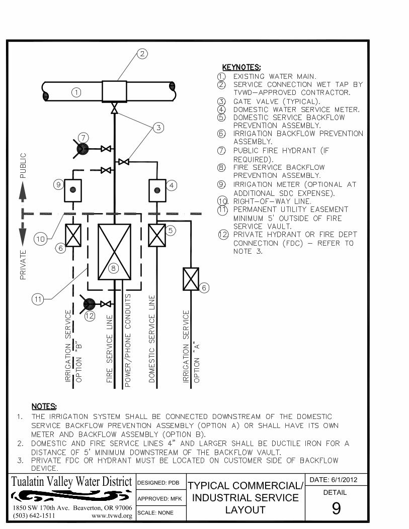
9 Typical Commercial/Industrial Service Layout 10 Typical Trench Backfill
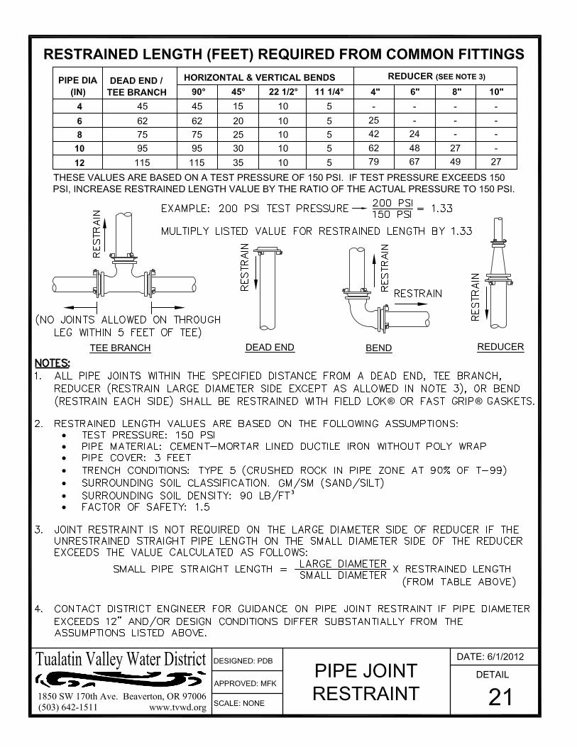
21 Restrained Length (Feet) Required from Common Fittings
50 Sample Station Installation 100 Typical Water Main and Fire Hydrant Location
101 Fire Hydrant Standard Installation
102 Fire Hydrant Clear Zone 200 Straddle Block
202 Phase Break End for Future Extension (4” – 10” Mainline)
203 2" Standard Blowoff (4” – 10” Mainline) 205 6” Standard Blowoff in Manhole
300 Vault Ladder Installation
310 Sump Pump Installation 601 1” Combination Air and Vacuum Valve
602 2" Combination Air and Vacuum Valve
702 1 ½" & Larger Meter Installation w/ Backflow Device 703C 3" - 6” Meter Installation by Contractor 763C 6" x 3" Meter Installation by Contractor
784C 8" x 4" Meter Installation by Contractor
811 4” Pressure Relief Vault, Contractor Installed
Standard Detail Title BF10 Typical Backflow Preventers for Lawn Sprinkler Systems
BF100 Double Check Valve Assembly
BF101 1” Double Check Assembly BF102 1-1/2", 2" & 2-1/2" Double Check Installation
BF103 Double Check Valve Assembly Customer Owned (Above Ground)
BF200 Double Check Detector Assembly

Water System Design and Construction Standards Table of Contents
TVWD Water System Standards June 2012 Page vi
BF201 Double Check Detector Assembly - Customer Owned (Above Ground) 3" - 10"
BF202 Reduced Pressure Detector Backflow Assembly 2-1/2” – 10” Customer Owned (Above Ground)
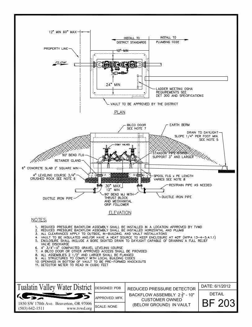
BF203 Reduced Pressure Detector Backflow Assembly 2-1/2” – 10” Customer Owned (Above Ground) In Vault
BF300 Reduced Pressure Backflow Assembly 2-1/2” – 10” Customer Owned (Above Ground)
BF301 1" Reduced Pressure Backflow Preventer BF302 1-1/2" & 2" Reduced Pressure Backflow Device
BF303 Reduced Pressure Backflow Assembly Customer Owned (Above Ground) In Vault
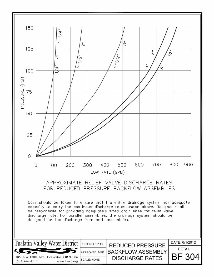
BF304 Reduced Pressure Backflow Assembly Discharge Rates BF500 Minimum Protection for Filling Tanker Trucks
BF501 Air Gap

Water System Design and Construction Standards Table of Contents
TVWD Water System Standards June 2012 Page vii
Definitions, Acronyms, and Abbreviations Definitions Contractor The person or entity employed by the Developer, Owner, or District in order to
implement water system improvements.
Developer The person or entity legally responsible for the development of land.
District The Tualatin Valley Water District.
District Engineer The District’s Chief Engineer, or his/her authorized representative.
Inspector The person employed by the District to observe construction and enforce the District’s Water System Standards and proper construction of water system improvements.
Owner The person or entity who possesses legal ownership of the land affected by the improvements.
Project Engineer The engineer in responsible charge of designing the water system improvements, who must be registered in the State of Oregon.
Standard Details Detail drawings showing specific installation details for water system components.
Standards The Tualatin Valley Water District Water System Design and Construction Standards.
Acronyms Note: When references to the following capitalized abbreviations are made, they refer to
Specifications, Standards or Methods of the respective association or agency.
ANSI American National Standards Institute
ASTM American Society for Testing and Materials
AWWA American Water Works Association
NSF NSF International (formerly National Sanitation Foundation)
ODOT Oregon Department of Transportation
UL Underwriter's Laboratories, Inc.
Abbreviations BCR Beginning of Curb Return G.I. Galvanized Iron
B.F.V. Butterfly Valve G.V. Gate Valve
B.O. Blowoff M.J. Mechanical Joint (fitting)
CARV Combination Air/Vacuum Release Valve P.E. Plain End (pipe)
D.I. Ductile Iron (pipe) ppm Parts Per Million
ECR End of Curb Return PSI Pounds Per Square Inch (pressure)
Flg. Flange (fitting) PRV Pressure Reducing Valve
fps Feet Per Second PUE Public Utility Easement

TVWD Water System Standards June 2012 Page 1-1
Section 1
General Requirements 1.1 Scope and Definitions
a. The Tualatin Valley Water District Water System Standards includes provisions, technical specifications, and requirements for construction within the Tualatin Valley Water District, and other entities managed by the District.
b. In addition to following these Standards, water system design and construction shall abide by all relevant codes, ordinances, and regulations. In cases of conflicting requirements, the more stringent standard shall apply.
c. Standard Details are included in these Standards to supplement the written specifications, but the written specifications shall have precedence over the standard details in the event of conflicts.
d. The District Engineer has the authority to recommend or allow deviations from these Standards in necessary circumstances, according to his or her best judgment.
e. Public health and safety shall be adequately protected in the Project Engineer’s designs and at all times during construction of water system improvements.
f. All construction and other water system-related work shall be performed by experienced workers using tools in good repair to a high quality of workmanship.
The Tualatin Valley Water District may revise the Standards at any time without prior notification. Any amendment shall take effect upon the date indicated in the amendment upon posting to the District’s website.
1.2 General Process for Water System Improvements a. In general, the process for designing and installing water system improvements
shall be as follows:
1. The Developer shall submit engineering plans prepared by the Project Engineer and sealed with professional engineers stamp in accordance with ORS 672, along with the plan review fee.
2. The District shall review the engineering plans. If changes and revisions are required, the Project Engineer shall revise and resubmit the plans.
3. Following approval of plans by the District, the Developer’s Contractor shall install the improvements in accordance with the approved plans.
4. The District’s Inspector’s shall monitor and inspect the work throughout construction to ensure compliance with the approved plans and District Standards.
5. Upon completion of the work, the Developer shall submit As-Built Drawings prepared by the Project Engineer.

Water System Design and Construction Standards Section 1
TVWD Water System Standards June 2012 Page 1-2
6. After final acceptance by the District, the Developer shall provide a one year warranty on the improvements.
b. Prior to initiating the project design, the Project Engineer shall contact the District Engineer, who may suggest or require a pre-design meeting to discuss the specific requirements for the project.
1.3 Preparation and Submittal of Engineering Plans a. All plans for water system improvements must be prepared and sealed by a
Project Engineer who is licensed by the state of Oregon.
b. Generally, engineering plans shall include the following information:
1. Existing and proposed utilities (sewer, storm, power, gas, telecom, cable, poles, etc.)
2. Existing and proposed curbs, sidewalks, driveways, mailboxes, and other street features.
3. Existing and proposed rights-of-way and easements.
4. Horizontal and vertical alignments of new public mains.
5. Size, material, and location of new and existing water mains and services.
6. Size, type, and location of new and existing water appurtenances, including:
i. Valves
ii. Hydrants
iii. Fittings (Bends, Tees, Crosses, Reducers)
iv. Pressure Regulators
v. Vaults
vi. Meters
7. Joint restraint requirements.
8. Cathodic protection requirements.
9. District Standard Details that are applicable to the project.
10. Existing and required easements for water improvements.
11. Proper call-outs and notation.
c. If applicable, include drawings showing:
1. Landscaping plans showing the layout of irrigation systems, backflow device(s), and any decorative water features.
2. Mechanical plans of boilers, chillers, and other water-consuming mechanical devices.
3. Plumbing plans with location of on-site backflow devices; fire line drawings showing plans of antifreeze (either potable or non-potable) loops, etc.

Water System Design and Construction Standards Section 1
TVWD Water System Standards June 2012 Page 1-3
d. All drawings submitted for review and approval shall be on sheets with a size of either 22 inches by 34 inches or 24 inches by 36 inches.
e. Minimum text height shall be 0.10 inch.
f. Plans shall include a cover sheet with the following information:
1. Project name.
2. Owner’s name, address, phone number, fax number, and email address.
3. Project Engineer’s name, address, phone number, fax number, and email address.
4. Contractor’s name, address, phone number, fax number, and email address.
5. Project location (Vicinity Map)
g. Submit plan review fee and three sets of subdivision drawings to the District Engineer for review and approval: one full set and two partial sets of drawing sheets showing only the water system improvements.
1.4 Approval of Engineering Plans a. The District Engineer’s approval of the sealed plans is required prior to the start
of any construction. Plan approvals are only valid for six months from the date of approval.
b. Any changes to approved plans initiated by the Project Engineer or as a result of field conditions must be resubmitted and approved by the District Engineer.
c. The Developer or their agent shall obtain all required permits.
d. Any property to be developed that is not currently within the District boundary shall be annexed into the District prior to extending water service to the site, unless an extra-territorial water line extension has been approved.
1.5 Construction Inspection a. The Developer’s Contractor shall contact the Inspector at least 48 hours prior to
any water system construction to request a pre-construction conference.
b. The District Engineer and Inspector shall have access to the project at all times in order to make routine visual inspections of the work.
c. No work shall be buried before it is inspected and accepted by the Inspector. Potholing of buried water lines may be required at the Developer's expense to allow verification that the installation meets the requirements of the Standards.
d. Should any inspection reveal that construction is not proceeding according to the approved plans and/or District Standards, the District Engineer or Inspector may order all work stopped and all defective work removed and replaced. If a revision is necessary, the Project Engineer shall provide the District Engineer with revised plans for review and approval before work resumes.
e. Work by Developer’s Contractor outside District’s normal business hours shall require a minimum of 48 hours notice to Inspector. Overtime costs for District inspection will be paid by the Contractor.

Water System Design and Construction Standards Section 1
TVWD Water System Standards June 2012 Page 1-4
1.6 Electronic "As-Built" Drawings a. Upon completion of new residential or commercial subdivisions, the Project
Engineer shall submit an electronic file of the final plat and as-built drawings.
b. Electronic files shall be submitted to the District Engineer via email as an attached file in AUTOCAD.DWG or .DXF format. Verify the appropriate format version with the District’s Inspector.
c. Alternatively, electronic files may be submitted on CD media or other approved means using the above-indicated file format.
1.7 Requirements for Acceptance of Water System Improvements The following items must be completed prior to final acceptance of water system improvements:
a. Compliance with all relevant Standards, including but not limited to standards for design, construction, disinfection, and pressure testing.
b. Completion of second lift of paving, ensuring that all valve boxes are raised and flush with surface. The District may approve the installation of water meters prior to placement of the second paving lift if:
1. It is during the winter period, approximately November 15 through March 15.
2. Weather and temperature conditions are unacceptable for final paving.
3. A deposit or bond in the amount of 10% of the value of the water system improvements, or a minimum of $5,000, is deposited with the District prior to release of the subdivision for water meter installation.
4. The Developer agrees to complete final paving within 30 days after paving conditions return to acceptable temperatures.
c. Request for final subdivision inspection and correction of any deficiencies identified by District staff at the final inspection walk-through.
d. Submission of electronic files for the project, as described in Section 1.6.
e. Provide documentation that any required easements and/or right-of-way dedications have been completed and recorded.
f. The District reserves the right to withhold installation of water meters until the project has been granted final acceptance.
1.8 Warranty a. A one-year warranty period shall be provided for the water system improvements
by the Developer. Any failure of materials and workmanship during the warranty shall be repaired or replaced to the District’s satisfaction at the Developer’s expense.
b. The warranty period shall begin on the date of final written acceptance of the project by Tualatin Valley Water District.

Water System Design and Construction Standards Section 1
TVWD Water System Standards June 2012 Page 1-5
1.9 Easements a. Where it is not practical or possible to install water system improvements within a
dedicated public right-of-way, the District may allow the improvements to be installed within a dedicated easement on private property.
b. Water line easements shall be centered on the pipe. Minimum easement widths shall be 15 feet for areas with vehicular access (roadways, parking lots, etc.) and 20 feet for areas without vehicular access. Additional width may be required for special circumstances such as slopes or other cases as determined by the District.
c. Easements for vaults or other water system appurtenances shall extend a minimum of 5 feet on all sides of the structure. Additional width may be required for special circumstances such as slopes or other cases as determined by the District.
d. Easements granted to the District shall allow for access, construction, operations, maintenance, replacement, reconstruction, and removal of the water system improvements.
e. The easement shall be solely for water systems improvements and not shared by other utilities or structures without the prior written consent of the District.
f. If access to the easement area and associated appurtenances is not directly available from a public right-of-way, an access easement along the most direct route of access shall be granted to the District.
g. Easement exhibits shall be prepared by a Professional Land Surveyor. Easement dimensions and language shall be subject to final approval by the District. Easements shall be recorded prior to final project approval.
1.10 General Design Requirements a. Any permanent appurtenance that is above sidewalk and/or finish grade shall be
at least 18 inches behind the sidewalk. No permanent signs, structures, or plant materials are allowed within three feet of District facilities.
b. In locations outside of the established right-of-way, mark water line appurtenances, such as valves, blowoff assemblies, and cathodic protection test stations, with a Carsonite marking post. Post shall be blue in color, a minimum width of 3.5 inches, and be set with the top of post three feet above finished grade.
1.11 General Materials Requirements a. Only materials designed for potable water service and meeting NSF Standard 61,
the American Water Works Association (AWWA) standards, and other applicable standards shall be used in those elements of the water system which may come in contact with potable water. All materials must be certified “lead-free”.
b. All materials used for water system construction shall be of new manufacture. No rebuilt, reconditioned, or previously used materials shall be used.

Water System Design and Construction Standards Section 1
TVWD Water System Standards June 2012 Page 1-6
1.12 General Construction Requirements a. Safety and Worksite Conditions
1. Project safety shall be the responsibility of the contractor.
2. Contractors shall use every reasonable precaution to safeguard the persons and property of the traveling public. It shall be the sole responsibility of the Contractor to furnish, place, and maintain the barricades, barriers, lights, signage, and flaggers necessary to protect the traveling public and their property.
3. Contractors shall abide by all OSHA and other applicable safety regulations.
4. All barricades and obstructions shall be protected at night by signal lights, which shall be suitably distributed and operated from sunset to sunrise.
5. Contractors shall provide and maintain sanitary facilities for employees in accordance with applicable regulations.
6. The Contractor shall clean all spilled dirt, gravel, or other foreign material caused by construction operations from all streets at the end of each day’s operation. Contractor shall adhere to all applicable erosion control requirements.
b. Permits and Road Closures
1. The Contractor or Developer shall obtain the appropriate utility permit(s) from the city, state, or county with jurisdiction for the streets or roads within the project work area prior to construction of system improvements.
2. Contractors shall comply with all rules and regulations of the applicable city, state, and county authorities regarding the closing of public streets or highways to use of public traffic. No road shall be closed to the public, except by express permission of the affected regulating authority.
c. Valve Operation Prohibited
1. Operation of valves in the District’s water system by anyone other than District employees is strictly prohibited. Contractors shall not open or close valves, or take any other action that may affect the operation of the existing water system, except as specifically required by the plans and specifications, and only with prior approval by the District.
2. The Contractor shall notify the District at least 48 hours in advance of valve operation and/or interruption of the existing service.
d. Interruption of Utility Service
1. In the event of accidental interruption of domestic water, sewer, storm drain, or other utility services, the responsible party shall immediately notify the District Inspector or District Project Engineer.
2. The responsible party shall arrange for restoration of service as promptly as possible and bear all costs of repair. In no case shall interruption of any water or utility services be allowed outside of working hours, unless prior approval is granted by the district.
e. Damage to Water System during Construction

Water System Design and Construction Standards Section 1
TVWD Water System Standards June 2012 Page 1-7
1. The District shall be notified immediately if any part of the water system is damaged in any way.
2. Repair of any damage to the District's facilities caused by a Contractor shall be made to the District’s Standards at the Contractor's expense. The District, at its option, may make the repairs and bill the Contractor on a time and materials basis.
f. Relocation of Existing Mains
1. Any water line relocation work that is a requirement of the development shall be performed by District crews at the Owner's expense on a time and materials basis unless otherwise authorized by the District. A deposit for the estimated cost of the work is required prior to commencement of the work.
g. Water Service Installation
1. All installation, relocation, or abandonment of service lines 2 inches in diameter and smaller shall only be performed by District crews unless otherwise authorized by the District.
h. Connections to the Water System
1. Connections to existing mains for new mains or services larger than 2 inches in diameter shall be wet-tapped by a pre-approved tapping contractor using proper equipment. Contact the District Engineer or Inspector for a current list of pre-approved tapping contractors.
2. Contractor shall notify the Inspector at least 48 hours prior to beginning installation, relocation, or abandonment of service lines larger than 2 inches in diameter.
i. Preservation of Land Survey Monuments
1. The Contractor shall preserve all existing survey monuments in and around the work area. If any survey monument will be disturbed by construction, it is the responsibility of the Developer or Contractor to hire a Professional Land Surveyor licensed in the State of Oregon to conduct a pre-construction survey and replace the affected monuments in accordance with state laws.
j. Preservation/Replacement of Existing Structures
1. Contractor shall preserve, repair, or replace all existing structures damaged during construction, including but not limited to storm sewers, catch basins, and culverts.
k. Substitution of Materials
1. Whenever any material, device, or process is specified by proprietary name, name of manufacturer, or catalog number, such specifications shall establish a standard of quality.
2. The specifications shall not prohibit the use of suitable products by other manufacturers of equal or better quality, and shall be allowed by the words "or as approved" or "approved equal."
3. In such cases, the Contractor shall submit complete data to the District Engineer for consideration of another material, device, or process, which shall be

Water System Design and Construction Standards Section 1
TVWD Water System Standards June 2012 Page 1-8
substantially equal in every respect to that specified. The District Engineer will determine whether a substitute material is acceptable.
4. Substitute materials shall not be used unless approved by the District Engineer in writing.

TVWD Water System Standards June 2012 Page 2-1
Section 2
Trench Excavation and Backfill 2.1 Types of Allowed Backfill
a. Class A backfill – compacted native material
1. Class A backfill requires District approval and shall only be considered for use in unpaved areas.
b. Class B backfill – compacted crushed rock granular material
1. Class B backfill shall be used in all paved areas.
c. Refer to Standard Detail 10.
2.2 Materials a. Class A Backfill – compacted native material
1. The District may require a geotechnical engineering investigation of the suitability of native materials for use in trench backfill.
2. Class A backfill material shall be free of organic material, wood, rocks larger than 6 inches in any dimension, and other debris.
3. The moisture content of Class A backfill material shall be no more than 5% above optimum during backfill placement and compaction.
b. Class B Backfill – compacted crushed rock granular material
1. Class B backfill material shall be crushed rock meeting the requirements of ODOT Standard Specifications Section 00641 and Section 02630.
2. Designated sizes shall be 1”-0” or ¾”-0” with no more than 5% passing the No. 200 sieve (wet analysis).
c. Bedding and Pipe Zone Material
1. Bedding and pipe zone material shall be Class B backfill material.
d. Foundation Stabilization Material
1. Foundation stabilization material shall be 2 1/2"-0” crushed rock meeting the requirements of ODOT Standard Specifications Section 00641 and Section 02630, or other material as approved by the Inspector.

Trench Excavation and Backfill Section 2
TVWD Water System Standards June 2012 Page 2-2
2.3 Pavement, Curb, and Sidewalk Removal a. Prior to excavation of the trenches, cut all pavements, curbs, and sidewalks,
regardless of the thickness, with a pavement saw or other approved pavement cutter.
b. The width of the pavement cut shall be at least equal to the required width of the trench at ground surface. The city, county, or state agency responsible for the street may require T-cutting or additional pavement milling prior to re-surfacing.
c. Removed pavement and concrete materials shall be hauled from the site to be recycled and not used for trench backfill.
2.4 Trench Width, Base, and Grade a. The width of trenches in which pipe is to be laid shall be 12 inches greater than
the nominal diameter of the pipe or 24 inches minimum, unless otherwise approved by the District Engineer.
b. Grade the full width of the bottom of the trench where the pipe is to be laid; additional excavation to accommodate pipe bells shall be required. The trench bottom shall be level across the width and on a uniform grade between grade breaks along the length of the trench.
2.5 Shoring, Sheeting, and Bracing of Trenches a. Trench safety, including but not limited to shoring and bracing design, shall be
the responsibility of the contractor.
b. Erect, maintain, and remove shoring, sheeting and bracing as required by the most stringent of all applicable laws, codes, and ordinances.
c. Where sheeting and bracing are used, increase trench widths accordingly by the thickness of the sheeting. Keep sheeting in place until the pipe has been placed and backfilled at the pipe zone.
d. Shoring and sheeting shall be removed as backfilling progresses in a manner that will not damage the pipe or permit voids in the backfill.
e. Foundation Stabilization
1. When the existing material in the bottom of the trench is unsuitable for supporting the pipe, excavate below the flow line of the pipe. If firm, native material is not present within three feet below the bottom of the pipe zone, contact the Inspector for further guidance on foundation stabilization.
2. Backfill the trench to the bottom of the pipe zone with approved material and compact.
2.6 Location of Excavated Materials a. During trench excavation, place the excavated material within the construction
easement or specified working area so that the excavated material does not obstruct any private or publicly traveled roadways.
Trench Excavation and Backfill Section 2
TVWD Water System Standards June 2012 Page 2-3
b. Pile material away from trenches so that the toe of the slope of the material excavated is at least 36 inches from the edge of the trench.
c. It shall be the Contractor's responsibility to determine the safe loading of all trenches with excavated material.
2.7 Removal of Water a. Provide ample means by which to promptly remove and dispose of all water
entering the trench for all phases of construction until completion of backfill at the pipe zone. These provisions shall apply during non-working as well as working hours.
b. Drainage of trench water through the pipe under construction is strictly prohibited.
c. The pipe shall be plugged during construction so that no groundwater or other foreign material may enter at any time.
d. Disposal of water from dewatering operation and flushing shall be the responsibility of the Contractor. Any applicable permits shall be obtained by the contractor and strictly adhered to.
2.8 Addition and Compaction of Backfill a. Bedding and Pipe Zone
1. Bedding shall be at least six inches in depth below the bottom of the pipe and shall extend across the full width of the trench.
2. The pipe zone shall extend from six inches below the bottom of the pipe to six inches above the top of the pipe barrel. The pipe zone material shall extend across the full width of the trench.
3. After the pipe is in place, backfill the pipe zone at an even rate such that there is an even layer of backfill on either side of the pipe at all times.
4. Compact the pipe zone by tamping in six inch lifts up to the horizontal centerline of the pipe. Each layer shall be compacted to at least 95% of its maximum density as determined by AASHTO T-99. No unfilled or uncompacted areas shall exist beneath the pipe.
5. Refer to Detail 10.
b. Class A Backfill
1. Place approved material in the trench above the pipe zone in lifts not exceeding 18 inches, loose measure.
2. Compact each layer by mechanical methods to 90% maximum density as determined by AASHTO T-99.
3. Mound backfill material to several inches above finished grade to account for minor settlement.
c. Class B Backfill

Trench Excavation and Backfill Section 2
TVWD Water System Standards June 2012 Page 2-4
1. Place approved material in the trench above the pipe zone in lifts not exceeding 12 inches, loose measure.
2. Compact each layer by mechanical methods to 95% maximum density as determined by AASHTO T-99.
3. Backfill trench to subgrade elevation and construct or re-construct the street structural section per applicable jurisdiction’s requirements.
d. Under no circumstances shall the Contractor allow sharp, heavy pieces of material to drop directly onto the pipe or the tamped material around the pipe.
e. The Contractor shall provide water as needed to facilitate compaction.
f. The agency having jurisdiction over the right-of-way (county, city, state) may have additional requirements or more stringent standards relating to trench backfill within the right-of-way. In these cases, the contractor shall perform the work in accordance with the more stringent standard and notify the Inspector of the discrepancy.
g. Settlement
1. Any settlement noted in trench backfill, finished surfacing, or structures built over the surfacing during the warranty period will be considered to be caused by improper compaction methods.
2. The Contractor shall correct settlement and restore any structures damaged by settlement to their original condition, or as required by road owner, at no additional cost to the District.
2.9 Compaction Testing a. Field compaction test results shall be evaluated based on a standard Proctor
(ASTM D698) laboratory test completed on a representative sample of the material being used as trench backfill.
b. A certified testing agency shall perform compaction testing and the Contractor shall provide the test results to the District. If results indicate that compaction or moisture content is inadequate, backfill material shall be removed and replaced prior to continuation of work.
c. Testing of backfill compaction shall include a test at the surface and at two-foot increments below the surface. Testing shall be conducted every 25 feet along the trench length or as directed by the District Engineer.
d. Any trench backfill not passing the compaction test and/or showing visible failure shall be rejected and replaced.
2.10 General Surface Restoration Specifications a. Asphalt Concrete and Portland Cement Concrete Paving
1. Asphalt concrete and/or Portland cement concrete pavement materials and installation shall conform to the current specifications and standards of the city, county, state or other agency having jurisdiction for the location where the work is to be performed.

Trench Excavation and Backfill Section 2
TVWD Water System Standards June 2012 Page 2-5
2. It is the responsibility of the paving contractor to confirm which agencies have jurisdiction as well as the current surface restoration requirements of each agency.
3. Any pavement markings within the work area that are damaged or removed as a result of the work shall be repaired or replaced by the paving contractor unless otherwise stated in the contract.
b. Protection of Structures
1. Provide whatever measures may be needed to protect the exposed portions of the bridges, culverts, curbs, gutters, posts, guard fences, road signs, and other features from splashing oil and asphalt from the paving operations. After paving is complete, remove any oil, asphalt, or dirt that is left behind on these features as a result of the paving operations.
2. Where water valve boxes, manholes, catch basins, or other underground utility appurtenances are within the area to be surfaced, the resurfacing shall be level with the top of the existing finished elevation of these facilities. If it is evident that these facilities are not in accordance with the proposed finished surface, notify the proper authority in order to have the facility altered before proceeding with the resurfacing around the obstruction, unless otherwise approved. Protect all covers during asphalt application.
c. Warranty Period
1. Contractor shall provide a warranty period of no less than one (1) year on pavement. During this period the contractor shall repair or replace, at no additional cost to Tualatin Valley Water District, any pavement failure caused by defective material, installation, or compaction. The warranty period shall begin at the time the project is accepted by the District.
Water Mains Section 3
TVWD Water System Standards June 2012 Page 3-1
Section 3
Water Mains 3.1 Design
a. The pipe cover shall be 36 inches unless otherwise approved or required by the Engineer.
b. Pipe Sizes
1. The minimum standard main size shall be six inches.
2. Four-inch mains may be permitted when ALL of the following conditions are met:
i. The run is less than 300 feet.
ii. There are no more than eight services.
iii. There is no possibility of future main extension.
iv. There is no need for a fire hydrant.
3. Fire hydrants shall not be connected to mains less than eight inches in diameter.
4. The District may require mains to be upsized to serve future development.
5. The District will make the final determination on the size of new mains.
6. Ten-inch and 14-inch pipe sizes are not allowed within the District.
7. Any hydraulic calculations that justify pipeline sizing shall be made using a Hazen-Williams "C" coefficient of 100.
c. Location of Mains
1. Water mains shall generally be located within the public right-of-way.
2. Water mains shall generally be located on the south and east sides of the street, six feet from the face of curb to the pipe centerline. Refer to Standard Detail 100.
3. Water mains along looped or curved streets shall not switch sides of the street.
4. Water mains in streets with development along only one side of the street shall be placed six feet from the face of the curb adjacent to the lots served. This minimizes service line length and avoids "long-side" connections to fire hydrants.
5. When it is not possible to install the main within a public right-of-way, the District may allow the main to be installed within an easement. See Section 1.9 for easement requirements.
d. Dead End Mains
1. Dead end mains generally are not allowed.
2. When dead ends are permitted by the District, a blowoff assembly is required.

Water Mains Section 3
TVWD Water System Standards June 2012 Page 3-2
3. If future extension of the street is anticipated, a line-size valve and two-inch blowoff assembly shall be installed at the end of the dead end line. See Detail 202 for phase break blow off detail.
4. If dead end main is in a cul-de-sac or future extension is not anticipated, a mechanical joint cap and two-inch standard blow off assembly shall be installed. See Detail 203 for two-inch standard blow off detail.
5. At the discretion of the District, a hydrant may be installed in lieu of a blowoff assembly on eight-inch and larger mains where future extension is not anticipated.
6. If future extension of the street is anticipated, dead end mains shall be extended to within five feet of the edge of pavement.
e. Water mains with a 12-inch or larger diameter shall have six-inch blowoff assemblies installed at locations specified by the District Engineer. See Detail 205 for six-inch standard blow off detail.
f. Pipe Alignment
1. Generally, the District encourages the use of deflected pipe joints in lieu of bend fittings.
2. Water main vertical alignment shall be designed to minimize high points where possible without resulting in excessively deep pipe installations.
3. Wherever it is necessary to deflect pipe from a straight line either in a vertical or horizontal plane, or where long radius curves are permitted, the amount of deflection allowed shall not exceed the values in Table 3. The manufacturer’s maximum allowable pipe joint deflection shall not be exceeded.
Table 1. Maximum Allowable Deflection of DI Pipe Restrained Joints (18-foot pipe length)1, 2
Pipe Diameter (in)
Mechanical Joint Maximum Deflection
Push-On Joint Maximum Deflection
Angle (degrees)
Offset per 18-foot pipe length (in)
Angle (degrees)
Length Offset per 18-foot pipe length (in)
4 8 31 5 18
6 7 27 5 18
8 5 20 5 18
10 5 20 5 18
12 5 20 5 18
1 The maximum deflection shall be determined from Table 1 or as recommended by the pipe manufacturer, whichever is less.
2 Safe deflection for 150 psi pressure. For higher pressure, reduce tabulated deflection 10 percent for each 10 psi added pressure and confirm allowable deflection with Inspector.
g. Restrained Joints
1. All joints on water mains shall be restrained.
2. Thrust restraint shall be provided by restrained joints that are approved by the pipe manufacturer.

Water Mains Section 3
TVWD Water System Standards June 2012 Page 3-3
3. Thrust blocks shall be used as thrust restraint at all hot tap locations. In all other cases where restrained joints are not feasible, thrust blocks may only be used with prior authorization by the District Engineer. Size and bearing area of thrust blocks is dependent on site-specific soils and other factors. Developer’s engineer shall provide stamped design calculations for thrust blocks on all pipes larger than 12 inches in diameter.
4. Straddle blocks shall be installed to provide thrust restraint at the direction of the Engineer. Size and bearing area of straddle blocks is dependent on site-specific soils and other factors. Minimum dimensions and reinforcement are shown in Detail 200. Developer’s engineer shall provide stamped design calculations for straddle blocks on all pipes larger than 12 inches in diameter.
h. Casing Pipe, Spacers, and Seals
1. Underground water mains crossing a railroad, an ODOT right-of-way, or a stream shall be installed in a casing pipe.
2. The size and extents of the casing shall be determined by the District Engineer on a case by case basis.
i. Cathodic Protection
1. Prior to pipeline design and construction, the District may require soil sampling and testing for corrosivity.
2. Testing requirements shall be determined on a case-by-case basis.
3. If soil conditions are found to be possibly corrosive to buried pipe and fittings, cathodic protection measures such as bonded pipe coatings, bonded pipe joints, sacrificial anodes, alternate pipe materials, or other measures may be required by the District.
3.2 Materials a. Generally, all pipe used within the District shall be ductile iron restrained joint
and all fittings shall be mechanical joint. The District Engineer may require or allow alternate types of pipe depending on site conditions, pipe size, and application.
b. All pipe and fitting shall be manufactured in the USA unless otherwise approved by the District.
c. Push On Joint Ductile Iron Pipe
1. All pipe shall be Class 52 ductile iron, unless specified otherwise by the District Engineer. Pipe shall conform to ANSI/AWWA C151/A21.51 and C104/A21.4.
2. Pipe shall have restrained joints such as TytonTM, as licensed by U.S. Pipe and Foundry Company, FastiteTM, as licensed by American Pipe, or equal, except where specifically shown or detailed otherwise.
3. Pipe shall be manufactured by:
i. U.S. Pipe
ii. Pacific States Cast Iron Pipe Company

Water Mains Section 3
TVWD Water System Standards June 2012 Page 3-4
iii. American Cast Iron Pipe Company
iv. Griffin Pipe
v. American Pipe
vi. District-approved equal
4. Ductile iron pipe must be cement-mortar lined.
5. A non toxic vegetable soap lubricant shall be supplied from the pipe manufacturer in sufficient quantities for installing the pipe.
d. Ductile Iron Fittings
1. Ductile iron fittings shall conform to ANSI/AWWA C110/A21.10 and/or ANSI/AWWA C153/A 21.53. Fittings shall have the following information cast upon them:
i. Manufacturer’s identification
ii. Country of manufacture
iii. Pressure rating
iv. Number of degrees or fractions of a circle (bends)
v. The District may require additional metallurgical documentation or other certifications.
2. Fitting joints shall have mechanical joint (MJ) ends, except where specifically shown or detailed otherwise.
3. The pressure rating for all fittings shall be equal to or greater than the pressure rating of adjacent pipe.
4. Lining
i. Fittings shall have a fusion-bonded epoxy lining of six to eight mil nominal minimum thickness. Lining shall conform to the requirements of ANSI/AWWA C550 and C116/A21.16.
ii. Alternatively, the fittings may be cement mortar lined to the same thickness specified for the pipe.
e. Mechanical Joint Fittings and Restraints
1. Mechanical joint fittings shall be ductile iron short pattern.
2. Fittings shall conform to ANSI/AWWA C110/A21.10 and shall be of a class at least equal to that of the adjacent pipe.
3. Bolts shall be domestic Cor-Ten or ductile iron tee-head bolts.
4. Mechanical Joint Restraints.
i. “Megalug style followers,” which utilize individually activated wedges that increase resistance to pullout as pressure or external force is increased, shall be provided as joint restraint.

Water Mains Section 3
TVWD Water System Standards June 2012 Page 3-5
ii. The joint restraint ring and wedge components shall be constructed of grade 60-42-10 ductile iron conforming to ASTM A536. Wedges shall be heat-treated to a minimum hardness of 370 BHN. The dimensions of the retainer gland shall be compatible with joint bells conforming to ANSI/AWWA A21.11/C111 and ANSI/AWWA A21.52/C153.
iii. The restraint shall be MEGALUG Series 1100 restraint device as manufactured by EBAA Iron, Inc., or equal.
f. Flanged Fittings
1. Flanged fittings shall conform to ANSI/AWWA C110/A21.10 and shall be faced and drilled Class 125 flanges that match ANSI B16.1 fittings.
2. Flanged fittings allowed under ANSI/AWWA C110/A21.10 are ductile or gray iron. Ductile iron is higher strength and is required by the District.
3. Flange bolts and nuts shall be Grade 304 or 316 stainless steel with standard course threads. Threads on bolts and nuts shall be coated with a food grade anti-seize material to prevent thread galling.
g. Gaskets
1. Gasket material for flanged joints in ductile iron pipe shall consist of 1/8-inch thick, full-face one-piece, cloth inserted, rubber gaskets conforming to Section 4 of ANSI/AWWA C207 and ANSI B16.21.
i. The gasket shall be cut with holes to pass bolts.
ii. Gasket material shall be free of corrosive alkaline or acidic ingredients.
iii. Lining shall conform to Section 3.2.5.
h. Restrained Joints
1. Joints shall be restrained using either mechanical joint restraints or Field LokTM (Tyton), FastiteTM (American) gaskets or equal (as approved by pipe manufacturer). Gaskets shall conform to ANSI/AWWA C111/A21.11, and shall be suitable for the specified pipe sizes and pressures. Gaskets should have stainless steel locking segments vulcanized into the gaskets to grip the pipe and prevent joint separation.
2. Thrust block and straddle block materials shall be 3,500 psi minimum compressive strength concrete and reinforcement (if required) shall be #4 minimum diameter steel rebar with a minimum tensile strength of 30 ksi.
i. Sleeves and Mechanical Couplings
1. Full-body sleeves for buried service shall be ductile iron with mechanical joint components. Sleeves shall conform to ANSI/AWWA C111/A21.11.
2. Mechanical couplings for non-buried service shall be ductile iron with rubber rings and ductile iron bolts and nuts. Couplings shall be Dresser, Smith Blair, or as approved.

Water Mains Section 3
TVWD Water System Standards June 2012 Page 3-6
j. Tapping Sleeves
1. Tapping sleeves shall be ductile iron, epoxy-coated steel, or stainless steel fittings as specified in Table 5.
2. Branch outlet from tapping sleeve shall be a minimum of Schedule 10 material thickness and shall have a test plug.
Table 2. Acceptable Tapping Sleeves
Size Sleeve Types
Size-on-Size
JCM 432
Ford FTSS
Mueller H-304
Smith Blair 665
Romac SST III (w/ stainless steel flanges)
Or equal stainless steel, MJ.
Size by Reduced Size,
12” or Less
JCM 452 stainless steel with outlet seal
Romac SST III
Ford FTSS
Mueller H-304
Smith Blair 665
Or equal
Size by Reduced Size,
Greater than 12”
JCM 532 stainless steel outlet sealed
Epoxy-coated steel with stainless steel bolts
Small taps,
1” and Smaller
Tap directly on the DI pipe.
See Chapter 6.
See Section 3.3.c and Detail 8 for tapping sleeve installation information.
k. Casing Pipe, Spacers, and Seals
1. Casing Pipe
i. Casing pipe shall be smooth steel conforming to ASTM A36 with minimum yield strength of 36,000 psi.
ii. The minimum wall thickness shall be as required by the jurisdiction governing the highway, railroad, or stream bed under which the casing will be installed. In no case shall the casing wall thickness be less than 1/4 inch.
2. Spacers
i. Casing spacers shall be 12” wide, two piece construction, and all stainless steel.
ii. The spacer shall have a minimum of four runners through 14” pipe size, six runners through 36” sizes and seven runners through 48” sizes to secure carrier pipe within the casing and to resist movement of the pipeline.
iii. Casing spacers shall be as manufactured by Cascade Manufacturing, Calpico, Inc., or approved equal.

Water Mains Section 3
TVWD Water System Standards June 2012 Page 3-7
3. Casing seals shall be Model “C” custom pull-on casing ends, as manufactured by Calpico, Inc., or approved equal.
l. Polyethylene Wrap.
1. Provide 8 mil low density polyethylene film, in tubular form, without tears, breaks or other defects conforming to the requirements of AWWA C105:
i. Raw material requirements:
a. Group 2 (linear)
b. Color: Black,
c. Dielectric strength: Volume resistivity, 1015 ohm-cm, minimum,
d. Density: 0.910 to 0.935 g/cm3
ii. Physical properties:
a. Tensile strength: 3,600 psi, minimum
b. Elongation: 700 percent, minimum
c. Dielectric strength: 800 V/mil thickness, minimum
d. Impact resistance: 600g, minimum,
e. Thickness: low-density polyethylene film shall have a minimum thickness of 0.008 inch,
f. Propagation tear resistance: 2,550 gf (grams force), minimum.
m. Polyethylene Tape and Primer: Provide 3-inch wide, plastic-backed, 12 mil black adhesive tape Polyken No. 900-12 and Polyken 1027 Primer, or approved equal.
3.3 Construction a. Cutting the Pipe
1. Cut pipe for inserting valves, fittings, or closure pieces in a neat and workmanlike manner without damaging the pipe or lining and so as to leave a smooth end at right angles to the axis of the pipe. Do not flame cut.
2. Cut ductile iron pipe with milling type cutter or saw.
3. Dress cut ends of push-on joint pipe by beveling, as recommended by the manufacturer.
b. Laying the Pipe
1. Pipe location, depth of cover, and other relevant requirements from Section 2.1 shall apply.
2. The pipe bedding, pipe zone, and backfill materials shall comply with Section 2.1. Check the grade with a straight edge before laying each section of pipe and correct if

Water Mains Section 3
TVWD Water System Standards June 2012 Page 3-8
necessary. Pipelines intended to be straight shall not deviate from straight alignment at any joint in excess of one inch horizontally or vertically.
3. At each joint, dig bell (joint) holes of ample dimensions in the bottom and sides of the trench to allow the joint to be properly made and to permit easy visual inspection of the entire joint.
4. Provide ample means of removing all water entering the trench, according to Section 2.1.8. Do not lay pipe in water or when, in the opinion of the District Engineer or Inspector, trench conditions are unsuitable.
5. Do not drop pipeline materials into the trench. Carefully lower all pipe and appurtenances into the trench by means of a crane or other suitable equipment to prevent damage materials and protective coatings.
6. Unless otherwise directed, lay pipe with bell end facing in the direction of the laying. For lines on steep slopes, face bells upgrade only.
7. Cleaning pipe and fittings
i. Clean the outside of the spigot and the inside of the bell with a wire brush. Remove all lumps, blisters, and excess coal tar coating from the bell and spigot ends of each pipe.
ii. Wipe all dirt, grease, and foreign matter from fittings and the ends of MJ pipe and push-on joint pipe.
iii. Do not allow any foreign material to enter the pipe during storage or placement in the trench.
8. Restrained Joint Pipe
i. Lay and join pipe with restrained type joints in strict accordance with the manufacturer's recommendations.
ii. After the first length of restrained joint pipe is installed in the trench, secure pipe in place with approved backfill material tamped under and along sides to prevent movement. Keep ends clear of backfill. After each subsequent section is joined, place backfill to the spring line to prevent movement.
iii. Lubricant for the pipe gaskets shall be furnished by the pipe manufacturer, and no substitutes will be permitted under any circumstances.
9. Mechanical Joint Fittings
i. Install the particular fittings furnished in accordance with the manufacturer's recommendations.
ii. Clean the ends of the fittings to remove all dirt, mud, and foreign matter by washing with water and scrubbing with a wire brush.
iii. Slip the gland and gasket on the plain end of the pipe. If necessary, lubricate the end of the pipe to facilitate sliding the gasket in place. Then guide the fitting onto the spigot of the pipe previously laid.
10. Flanged Fittings
i. Bolts for flange fittings shall be full-nut installation (i.e., three full threads showing past nut).

Water Mains Section 3
TVWD Water System Standards June 2012 Page 3-9
ii. Coat threads on bolts and nuts with a food grade anti-seize material to prevent thread galling and torque to manufacturer’s recommended torque.
iii. Flanged fittings shall be fully wrapped with three layers of 8 mil polyethylene sheet secured with polyethylene tape.
c. Tapping Sleeves
1. Coordinate with District Inspector at least 48 hours prior to tapping. Inspector shall be onsite to witness tapping.
2. Tapping sleeves shall be installed per the manufacturer’s instructions. Generally, the installation process for tapping ductile iron or cast iron pipe shall be as follows:
i. Clean all dirt, corrosion, and other foreign material from the pipe surface.
ii. Verify pipe diameter and tapping sleeve size.
iii. Apply pipe joint lubricant to pipe and gasket.
iv. Place the saddle section of the sleeve on the pipe and mate the band section with the saddle section. Ensure that gasket is properly positioned and that no foreign material is trapped between the pipe and gasket.
v. Install lug bolts, position the sleeve, and hand tighten the lug bolts to hold the unit in place.
vi. Tighten the bolts according to the manufacturer’s recommended sequence to the recommended torque and verify final torque several times throughout the installation process.
vii. Install flange gasket, attach tapping valve per manufacturer’s instructions, and support the assembly with blocking and shims.
viii. Pressure test the valve and sleeve assembly and check for leaks.
ix. Verify proper bolt torque, assembly alignment, and cutter size.
x. Attach the drilling machine to the tapping valve and support entire assembly with blocking and shims.
xi. Tap pipe, close valve, and verify bolt torque on tapping sleeve.
xii. Open tapping valve slightly to flush any foreign material and provide pipe coupon to Inspector.
xiii. Ensure that all pipes and valves are fully supported with compacted crushed rock bedding per Section 2.2.b prior to backfilling.
d. Thrust Blocks
1. Thrust blocks shall be poured monolithically between the pipe and undisturbed native soil.
2. Fittings shall be wrapped in three layers of 8-mil polyethylene sheet secured with polyethylene tape prior to concrete placement.
3. All joints and fittings shall be accessible for repair after thrust blocking is in place.
e. Straddle Blocks

Water Mains Section 3
TVWD Water System Standards June 2012 Page 3-10
1. Straddle blocks shall be poured monolithically against the pipe and undisturbed native soil.
2. Straddle blocks shall be poured around a minimum of two “Megalug style followers” in accordance with Section 3.2.e.4 and installed per manufacturer’s recommendations.
3. Ensure that no unrestrained joints exist between the straddle block and pipe sections or fittings that are to be removed.
4. Ensure concrete straddle blocks have cured sufficiently before removing pipe sections or fittings or otherwise inducing a load on the straddle block.
5. See Detail 200.
3.4 Hydrostatic Testing, Flushing, and Disinfection a. Hydrostatic Test
1. All pipelines intended to carry potable water shall be tested and disinfected before placing in service.
2. The Contractor shall perform pressure and leakage tests on all newly laid pipe in accordance with District Standards. The District Engineer or Inspector shall be notified a minimum of 24 hours prior to testing and shall monitor the tests.
3. The extents of pipeline sections to be tested will be determined by the District Engineer.
4. The tests shall be conducted after the trench has been completely backfilled and compacted.
5. Equipment and Materials:
i. Two approved graduated containers.
ii. Pressure gauges measuring in two-pound increments to max test pressure.
iii. Pump capable of providing adequate pressure for test procedure.
iv. Suitable hose and suction as required.
6. Test Procedure
i. After the trench has been backfilled and compacted, fill the pipe with water with an approved method that protects the existing distribution system from possible contamination. The new mains being testing shall remain isolated from the existing water system.
ii. At the section of the line with the lowest elevation, use a pump to apply a test pressure of 150 psi or 1.5 times the normal working pressure, whichever is greater. Verify required static pressure with TVWD inspector.
iii. Isolate the pump and hold the pressure in the line for 60 minutes, unless otherwise directed by the District Engineer.
iv. At the end of the test period, operate the pump until the test pressure is again obtained.

Water Mains Section 3
TVWD Water System Standards June 2012 Page 3-11
v. Measure the amount of water required to restore the test pressure. To measure accurately, the pump suction shall be in a barrel or metered.
7. Leakage
i. Leakage is defined as the volume of water necessary to restore the specified test pressure at the end of the test period.
ii. No pipe installation will be accepted if the leakage is greater than the number of gallons per hour as determined by the following equation:
· · .
148,000
where:
L = Allowable leakage (gal/hour) D = Nominal pipe diameter (inches) S = Length of pipe tested (feet) P = Average test pressure (psi)
iii. Should any hydrostatic test result in leakage greater than allowed, locate and repair the defective joints, pipe, or appurtenances and retest the pipeline. Repeat until leakage is below the specified allowance.
b. Flushing
1. Before disinfection, flush all foreign matter from the pipeline. Coordinate flushing activities with Inspector at least 24hours in advance of flushing.
2. Provide hoses, temporary pipes, ditches, etc, as required to dispose of flushing water without damage to adjacent properties. De-chlorinate discharged water utilizing best management practices.
3. Flushing velocities shall be as least 2.5 fps. For large diameter pipe where it is impractical to flush the pipe at 2.5 fps, clean the pipe in place from the inside by brushing and sweeping, then flush the line at lower velocity and discharge at least twice the volume contained in the section of pipe being flushed.
4. After disinfection, flush the water from the line until the water through the line has chemical and bacteriological properties equal to the permanent source of supply.
c. Disinfection of Pipelines

Water Mains Section 3
TVWD Water System Standards June 2012 Page 3-12
1. Pipelines intended to carry potable water shall be disinfected before placing in service. Disinfection procedures shall conform to ANSI/AWWA C651 in accordance with OAR 333-061-0050 (10) (c) and as hereinafter modified or expanded.
2. Disinfection shall be accomplished using the continuous feed method to introduce a chlorine solution with a free chlorine residual of 25 to 30 mg/L in a manner that results in thorough wetting of all surfaces and the discharge of all trapped air. A free chlorine residual in excess of 50 mg/L will not be allowed without specific approval by the District Engineer.
3. The disinfection mixture shall consist of either calcium hypochlorite or sodium hypochlorite, and shall be prepared by the following:
i. When using calcium hypochlorite, first mix the dry powder with water to make a thick paste, and then thin to approximately a 1% solution (10,000 mg/L chlorine).
ii. When using liquid sodium hypochlorite, dilute the liquid with water to obtain a 1% solution.
iii. The required proportions of hypochlorite to water are listed in Table 6:
Table 3. Hypochlorite Solution
Product Quantity Water Volume
Calcium Hypochlorite,1 Ca(ClO)2
65-70% Cl 1 lb 7.5 gal
Sodium Hypochlorite,2 NaClO,
5.25% Cl 1 gal 4.5 gal
1 Comparable to commercial products known as HTH, Perchloron, and Pittchlor. 2 Known as liquid laundry bleach, Clorox, and Purex.
4. Injection into Pipeline
i. Inject the chlorine solution within the first 8-feet at the beginning of the pipeline section to be treated through a corporation stop or suitable tap in the top of the pipeline.
ii. The disinfection mixture shall be injected into the pipeline at a measured rate while fresh water is allowed to flow through the pipeline at a measured rate so that the chlorine-water solution is of the specified strength.
iii. Chlorinating devices for feeding the hypochlorite solutions must provide means for preventing the backflow of water.
iv. Do not place concentrated quantities of commercial disinfectant in the line before it is filled with water.

Water Mains Section 3
TVWD Water System Standards June 2012 Page 3-13
5. Operate all valves, hydrants, and other appurtenances during disinfection to assure that the disinfection mixture is dispersed into all parts of the line, including dead ends, new services, and similar areas that otherwise may not receive the treated water. Use check valves if necessary.
6. Retention Period
i. The chlorine solution shall be retained in the pipeline a least 24-hours to destroy all non-spore forming bacteria. At the end of the retention period, the disinfection mixture shall have a concentration of at least 10 mg/L of chlorine. To minimize damage to cement mortar lining in ductile iron pipe and fittings, disinfection solution contact time shall not exceed 60 hours.
ii. If the residual measurement after 24-hours is found to be 10 mg/l or more, the chlorine solution shall be drained and the pipeline flushed with potable water.
iii. If the residual is less than 10 mg/L, the pipeline shall be flushed, re-chlorinated and rechecked until a final residual of 10 mg/l or more is achieved after a 24-hour standing time.
iv. If the residual is greater than 10 mg/L, follow the bacteriological test procedure in Section 3.4.e
7. Disposal of Disinfection Water
i. Dispose of disinfection water in an approved manner.
ii. Do not allow disinfection water to flow into a waterway without adequate de-chlorination in accordance with ANSI/AWWA C655 “Field Dechlorination” to eliminate the chlorine residual.
8. Bacteriological Test
i. Provide access to sampling locations at the end of a 24-hour retention period, if the chlorine residual is greater than 10 mg/L, flush the disinfection water from the pipeline until the water through the line is equal in chemical and bacteriological properties to the permanent source of water.
ii. After flushing disinfection water is complete, coordinate with TVWD staff to have them collect the first bacteriological (total coliform) sample. After 24-hours and written confirmation from an approved laboratory that the first sample passed (i.e., free of coliform), then collect a second bacteriological sample. If trench water and/or excessive quantities of dirt or debris have entered the pipeline during construction, bacteriological samples may be required at intervals of 200-feet in the vicinity of the occurrence.
iii. After the results of the second sample are available, if both tests indicate the water is free of coliform organisms, coordinate placing the pipeline in service with District personnel.

Valves and Valve Boxes Section 4
TVWD Water System Standards June 2012 Page 4-1
Section 4
Valves and Valve Boxes 4.1 General Requirements
a. Isolation Valve Size, Spacing, and Location
1. Valve size shall match water main size.
2. Valves 8 inch and smaller, as well as all tapping valves, shall be gate valves. Valves larger than 8 inch shall be butterfly valves. All valves shall open with a counterclockwise rotation of a 2-inch square nut.
3. In general, spacing between isolation valves shall not exceed 800 feet.
4. Valves shall be installed on each branch of a tee or cross fitting unless otherwise directed by the District Engineer.
5. Refer to Detail 1
b. Pressure Reducing Valves
1. The location, size(s), configuration, and settings of pressure reducing valves (PRVs, regulators) will be determined by the District Engineer to work in conjunction with the District’s existing network of pressure zones.
2. PRVs shall be installed in a vault which shall conform to Chapter 7 of these Standards.
3. PRVs shall be equipped with an adequately sized pressure relief valve located less than 500 feet downstream (low pressure side) of the valve. Pressure relief valves shall be located in an area where discharge is easily visible from the street, but where discharge will not cause flooding or property damage. Pressure relief valves shall be installed in a vault which shall conform to Chapter 7 of these Standards.
c. Strainers
1. An approved "H" strainer shall be installed within a distance of ten pipe diameters upstream of the pressure reducing valves.
d. Air and Vacuum Release Valves
1. An air release valve is required when the pipe has a high point that is at least one pipe diameter higher than the remainder of the pipe segment.
2. On 16-inch and larger diameter pipelines, air and vacuum release valves may be required at additional locations.
3. The air and vacuum release valves shall permit the release of large volumes of air when the line is being filled with water, the release of smaller amounts of accumulated air under normal operating conditions, and the re-entrance of air into the line to break any vacuum caused by the water leaving the line rapidly.

Valves and Valve Boxes Section 4
TVWD Water System Standards June 2012 Page 4-2
4. Generally, 12-inch and smaller mains shall have 1-inch air and vacuum release valves and mains larger than 12 inches in diameter shall have a 2-inch or larger air and vacuum release valves as determined by the District Engineer.
e. The valves shall be designed to operate under working pressures of 150 psi or greater, (if needed), and shall have been tested at a pressure not less than 300 psi.
4.2 Materials a. Gate Valves
1. Gate valves shall be ductile iron body, bronze mounted, resilient seat, NRS valves with O ring seals, and shall conform to ANSI/AWWA C509 and C515 for ductile iron body valves.
2. All exposed fasteners shall be Grade 304 or 316 stainless steel.
3. Valves shall open when the stem is rotated counterclockwise. Unless otherwise shown, valves shall have 2 inch square wrench nut.
4. Joint materials shall conform to ANSI/AWWA C111/A21.11.
b. Butterfly Valves
1. Butterfly valves shall be the rubber seated type, suitable for direct burial service. Valve shall be equipped with ductile iron body and 304 stainless steel shaft with 304 stainless steel journals. The butterfly valves shall conform to ANSI/AWWA C504 for Class 150B.
2. All exposed fasteners shall be 304 or 316 stainless steel.
3. Valves shall withstand 150 psi or greater (if needed) working pressure and 150 psi pressure differential across the valve.
4. Valve disc shall be ductile iron alloy conforming to ASTM A536 Type 1, chrome edged ductile iron with Buna N rubber seat bonded to the valve body, or ductile iron with rubber disc seat and 304 stainless steel mating surface attached to the valve body conforming to ANSI/AWWA C504, Section 4.3.5.3. Shaft and disc seals shall be designed for a drip tight seal.
5. Joint materials shall conform to Section 2.2 and ANSI/AWWA C111/21.11.
c. Acceptable Manufacturers
1. Only valves from the following manufacturers shall be provided for installation in the District's facilities:
i. Kennedy Valve
ii. M & H Valve Company
iii. Clow Valve Company
iv. American Flow Control
v. Mueller Co.
vi. AVK Group

Valves and Valve Boxes Section 4
TVWD Water System Standards June 2012 Page 4-3
d. Butterfly Valve Operators
1. Butterfly valves shall be furnished with totally enclosed, integral valve operator designed to withstand a minimum of 300 ft lb input torque without damage to the valve or operator.
2. Operators shall be fully gasketed, grease packed, and designed to withstand submersion in water to a pressure of 10 psi.
3. Operators shall have a 2 inch square wrench nut.
4. Butterfly valves shall open with a counterclockwise rotation of a 2-inch square nut. A minimum of 30 turns of the operating nut shall be required to move the disc from a fully opened position to a fully closed position.
5. Operator Extensions
i. If the operating nut is deeper than 48 inches below finished grade, provide steel operating extensions to bring the operating nut to 24 inches below the ground or pavement surface.
ii. The operator extension shall have a steel disc to allow centering of the stem in the valve box. Disc shall be located directly below the top operator nut and no less than six feet apart if the extension is eight feet or more in length.
iii. See Standard Detail 5 for typical valve operator extension.
e. Valve Boxes for Buried Gate and Butterfly Valves
1. Valve boxes shall be one piece, cast iron type as manufactured by Olympic Foundry, or approved equal. The valve box and cover shall be No. VB910 with a "W" cast into the top.
2. A 6-inch diameter type ASTM D3034 SDR 35 PVC pipe shall be used as a spacer for the lower portion of the valve box. Length of spacer shall be as required depending on depth to operating nut.
f. Pressure Reducing Valves
1. Valves shall be Clayton Model 90-01 or 690-01 as manufactured by Cla-Val Co., or approved equal.
2. The PRV shall be a hydraulically operated, diaphragm-actuated, globe pattern valve, equipped with a resilient, synthetic rubber disc forming a tight seal against a single removable seat insert.
3. Diaphragm
i. shall not be used as a seating surface. No packing glands, or stuffing boxes, or valves with pistons are permitted.
ii. Repairs shall be possible without removing the valve from the pipeline.
iii. The diaphragm assembly shall be fully guided at both ends by bearings in the valve cover and seat. The diaphragm assembly shall be the only moving part and shall form a sealed chamber in the upper portion of the valve, separating operating pressure from line pressure.

Valves and Valve Boxes Section 4
TVWD Water System Standards June 2012 Page 4-4
4. The pilot control shall be a direct-acting, adjustable, spring-loaded, normally-open diaphragm valve, designed to permit flow when controlled pressure is less than the spring setting. A fixed orifice shall be included in the control system. All pilot control materials shall be 304 or 316 stainless steel.
5. The main valve and body shall be of ductile iron construction. The main valve trim shall be brass (QQ-B-626), bronze (ASTM B61), and 303 stainless steel. The pilot control system shall be of cast bronze (ASTM B62) with stainless steel trim and tubing.
6. Pilot systems shall have an adjustment range of 30-300 PSI.
7. The PRV shall be furnished with an internal and external 12 mil protective coating with an FDA approved fusion-applied epoxy resin.
8. Valves shall accommodate at least 100 psi greater than the normal upstream working pressure in case of surge.
g. Pressure Relief Valves
1. Valves used for pressure relief shall meet all of the requirements of Section 4.2.f (pressure reducing valves).
h. ‘H’Strainers
1. Strainers 1" through 2" shall be 250 lb Apollo International TCG Series, or equal, WSP-rated strainers constructed from high-tensile ASTM A-126 Class B cast iron with blow-off connections and easily removable cylindrical screens. A tapered seat allowing screens to be self-cleaning and tight fit shall be provided.
2. Strainers 3" and larger shall be Class 125 or 250 as applicable for the system pressure, Apollo International FC1 or FC2 Series, or equal. Strainers shall have flanged connections.
3. Self-cleaning shall be accomplished by opening the blow-off connection.
i. Air and Vacuum Release Valves
1. The valve inlets shall have iron pipe threads. The air and vacuum release valves shall be ARI Model D-040-C
2. The pipe used for the air release valve assemblies shall be brass or copper tubing at the inlet and shall conform to Standard Details 601 and 602.
3. Connection to main shall be per the requirements of Chapter 6 (service lines).
4. Enclose in Carson meter boxes or approved equal: for 1-inch size, Model No. 1730D P15L, and for 2-inch size, Model No. 1730D-P15L.
4.3 Construction a. Gate and Butterfly Valve Installation
1. Before installation, the valves shall be thoroughly cleaned of all foreign material, and shall be inspected for proper operation to verify that the valves seat properly.
2. Valves shall be installed so that the stems are vertical, unless otherwise directed.

Valves and Valve Boxes Section 4
TVWD Water System Standards June 2012 Page 4-5
3. Wrap valve body in three layers of 8-mil polyethylene sheet secured with polyethylene tape prior to backfilling.
4. Joints
i. Joints shall conform to ANSI/AWWA C600. Valves shall be installed in accordance with Standard Detail 3.
ii. Faces of flanges shall be cleaned thoroughly before flanged joint is assembled. After cleaning, the gasket shall be inserted and the nuts tightened uniformly around the flange.
iii. After tightening nuts, three full threads shall be showing on the end of the bolt where it is exposed beyond the nut.
iv. Joints shall be tested with the adjacent pipeline for leakage. If joints leak under test, valves shall be disconnected and reconnected, and the valve and/or pipeline retested.
b. Gate and Butterfly Valve Boxes
1. Center the valve boxes and set plumb over the wrench nuts of the valves. Valve boxes shall not rest on the valve body. Set the valve box covers flush with the surface of the finished pavement.
2. Cut extensions to the proper length so that the valve box does not ride on the extension when set at finished grade.
3. Backfill shall be the same as specified for the adjacent pipe. Place backfill around the valve boxes and thoroughly compact to a density equal to that of the adjacent trench, avoiding damage to or displacement of the valve box. Misaligned valve boxes shall be excavated, centered, plumbed, and backfilled at the Contractor's expense.
4. Where the valve is located in an unpaved area, the Contractor shall pour a concrete pad around the valve box. The concrete shall be 24 inches square by 4 inches thick, and shall be placed on a base of four inches of compacted crushed rock. Crushed rock shall meet the requirements of Section 2.2.b. Refer to Detail 3 for concrete pad.
5. Valve boxes shall be installed in conformance with Standard Detail 3.
c. Air and Vacuum Release Valve Boxes
1. Thoroughly compact the gravel beneath the concrete box and set the box so that it conforms to the elevation of the ground.
2. Place at least 12 inches of crushed rock beneath the air release valve. Crushed rock shall meet the requirements of Section 2.2.b.
3. Allow at least six inches of clearance between the street ell and the box top.
4. Test and disinfect air valve assemblies in conjunction with the pipeline.

Fire Hydrants Section 5
TVWD Water System Standards June 2012 Page 5-1
Section 5
Fire Hydrants 5.1 Fire Hydrant Locations
a. Fire hydrants generally shall be placed at the radius point of curb returns at street intersections. Midblock installations may be approved by the District but are not preferred. If installed at a midblock location, hydrant shall be placed at a property line between adjacent lots.
b. Fire hydrants shall be placed 18” behind top face of curb in a planter strip or 18” behind curbtight sidewalks. Refer to Standard Details 100 and 101.
c. Section 508.5 of the Oregon Fire Code states that no part of any single family residential building shall be greater than 400 feet from a hydrant, as measured along the most practical accessible route.
d. No part of any commercial, industrial, or multiple family residential building shall be greater than 250 feet from a hydrant, as measured along the most practical accessible route.
e. No concrete, fencing, vegetation, or other obstructions interfering with the hydrant operation shall be installed in the hydrant clear zone. The clear zone is a triangular area that extends three feet behind a hydrant, five feet on each side, and is 20 feet wide at the curb. Refer to Standard Detail 102.
f. Place hydrants so as to provide complete accessibility and minimize possibility of damage from vehicles or injury to pedestrians.
5.2 Materials a. Fire hydrants shall be of the break flange or safety top type. Hydrants shall
conform to ANSI/AWWA C502 and shall be yellow above the ground line.
b. The normal depth of bury shall be four feet.
c. Hydrants shall be connected to the main with 6-inch ductile iron pipe per the requirements of Chapter 3.
d. Fire hydrants shall have nominal 5¼-inch main valve openings, have 6-inch bottom connections, and be equipped with two 2½-inch hose nozzles and one 4½-inch pumped nozzle. Nozzle threads shall be American National Standard, and inlet connections shall be mechanical joint.
e. Operating nut shall be 1½-inch national standard pentagon nuts.
f. The main valve shall be equipped with O ring seals and shall open when turned counterclockwise.
g. Only the following hydrants shall be provided for installation:
1. Mueller Centurion or Super Centurion

Fire Hydrants Section 5
TVWD Water System Standards June 2012 Page 5-2
2. Kennedy K-81
3. Waterous Pacer
4. M & H Model 129
5. American AVK
h. Drain rock for hydrant installation shall be 1-1/2”-3/4” and meet the requirements of ODOT Section 00430.11.
5.3 Construction a. Hydrant Installation
1. Hydrant installation shall conform to Standard Details 100, 101, and 102 as well as Section 3.7 of ANSI/AWWA C600, except where otherwise specified.
2. Connect to existing mains with tapping sleeve and gate valve installed per Section 3.3.c and Standard Detail 8. Tapping valve shall be flange by MJ gate valve and shall match hydrant line size.
3. For hydrant installations in conjunction with new main construction, connect to main with standard MJ by MJ by flange tee fitting and flange by MJ gate valve.
4. Do not excavate below sub base grade. Backfill overexcavated areas with crushed rock per the requirements of Section 2.2.b to provide a firm foundation.
5. Provide a square, level, concrete pier block underneath the hydrant. Block shall be eight inches thick and 12 inches on each side.
6. Place hydrant carefully to avoid damage to the pier block. Jointing procedures shall conform to Section 4.3 of ANSI/AWWA C600.
7. All joints shall be restrained using MJ restrained joint follower glands per Chapter 3.
8. After hydrant is in place and connected to the pipeline, place temporary blocks to maintain the hydrant in a plumb position during subsequent work.
9. Place geotextile fabric on base rock before placement of drain rock around base block and hydrant bottom after hydrant has been placed. The drain rock pocket shall be not less than four cubic feet, and the top of gravel shall be not less than six inches above the hydrant drain opening. Once drain rock is in place bring remaining geotextile fabric over the top of the drain rock. Do not connect drainage system to sewer.
10. Set all hydrants plumb and nozzles parallel with, or at right angles to, the curb. When placed behind the curb or sidewalk, set hydrant barrel so that no portion of the pumper hose nozzle cap is less than 18 inches from the top face of the curb or backside of the sidewalk (if curbtight).
11. With the pumper nozzle facing the curb, set hydrants so that the safety flange is a minimum of three inches and a maximum of six inches above finished grade or sidewalk level.
12. Improperly positioned hydrants shall be disconnected and relocated at the Contractor's expense.

Water Service Connections Section 6
TVWD Water System Standards June 2012 Page 6-1
Section 6
Water Service Connections 6.1 General Requirements
a. The customer shall pay for service installations in advance, based on meter size. Contact the District for fees.
b. For new services in partitions and subdivisions, the Developer shall submit a copy of the preliminary plat showing lot numbers at least ten days prior to prepayment of service fees.
c. Service installation fees are based on excavation of clean native materials. Extra costs, including but not limited to excavation of hard rock material or boulders, removal of excess material, and re-compaction for trenches, shall be borne by the Developer.
d. Curbs
1. Curbs shall be installed prior to the installation of service lines and meter boxes. The area behind the curb shall be leveled within ten feet of the back of curb to allow room to facilitate the installation of service boxes at proper elevation.
2. If no curbs are planned, meter location and grade hubs shall be staked for each meter. See Standard Details 7, 7D, 7PD, 7P for water service typical installations.
3. The lot lines shall be clearly marked with lot numbers on the face of curb before service layout will be completed by the Inspector. The District’s installation crew will be notified once the service layout has been completed.
e. Service Installation
1. All water meters, meter boxes, meter vaults, and service lines and taps for 2-inch and smaller services shall be installed by District crews unless otherwise authorized by the District Engineer. Service installation will be scheduled only after work activities outlined in Section 6.1.d have been completed.
2. Water service installation shall be after road subgrade is cut and road baserock is installed, and before installation of “dry” utilities is complete. Otherwise, additional costs may be incurred. The District will not be responsible for restoring finished subgrade.
3. 1” and smaller taps for service connections shall be tapped directly into the ductile iron pipe. Taps larger than 1” shall use a tapping saddle.
f. Water Services and Meters
1. Pressure in Mains
i. District policy is to provide water service at a minimum pressure of 50 psi. Available pressure at specific locations may fall below this value depending on geographic features within a particular pressure zone.

Water Service Connections Section 6
TVWD Water System Standards June 2012 Page 6-2
ii. Where the pressure exceeds 80 psi, the District may require Developers to install a pressure reducing facility such as a vault housing pressure reducing valves (PRVs) on the main, or individual pressure regulating devices on each service line on the customer’s side of the meter as required by plumbing code.
2. Provision of Water Meters
i. Each individual tax lot (residential) shall have a separate water meter.
ii. If the structure on a single tax lot is a duplex or triplex, individual meters for each unit will be installed upon request at the time that the dwelling is constructed.
iii. Tax lots with more than four dwelling units are considered “multi-family use,” which is in the District’s commercial class and shall require a master meter.
3. Meter Sizes
i. The size of water meters shall be based on the total demand as reflected by the number of fixture units in the plumbing system. The meter size shall be determined according to methods and procedures outlined in Section 610.4 and 610.8 or Section 610.5 of the Uniform Plumbing Code (UPC).
ii. Where practical, 5/8-inch and 3/4-inch meters will be served by a 1-inch copper service line with double, or U-branch, service connections. The two meters will be installed in separate meter boxes located adjacent to the lot line.
iii. 1-inch and larger meters will be served from a single service line connected to the water main.
Contact the District Engineer for requirements for meters larger than two inches.
4. Location of Meters
i. The District generally places meters at the edge of the public right-of-way near the intersection of a property line. The District has the authority to move or change placement of water meters within the PUE.
ii. Meters 1-inch and smaller shall be located in the PUE adjacent to the right-of-way at the property line.
iii. Meters 1½-inch and larger shall be located in a vault on the Developer's property in a dedicated easement adjacent to the street right-of-way. The easement dimensions shall extend ten feet beyond each outside wall of the meter vault.
iv. No other utilities shall be located within three feet of a meter or service line.
v. Private Streets. Individual meters serving homes on private streets shall be installed in clusters or banks adjacent to the entrance of the private street. Refer to Standard Details 7, 7D, 7P, 7PD, and 9.
5. Backflow prevention assemblies are required on all meters 1½ inches and larger and for any size meter serving a high hazard facility. See Chapter 8 for further information on backflow assemblies.

Water Service Connections Section 6
TVWD Water System Standards June 2012 Page 6-3
6.2 Materials a. This section is applicable to 2-inch and smaller water service connections. For
installation of water service connections larger than two inches, contact the District Engineer for installation specifications.
b. Corporation Stops
1. Corporation stops for 1-inch copper service lines shall have CC thread inlet and compression connection outlet and shall be Ford F600, or approved equal.
2. Corporation stops for 1½-inch and 2-inch copper services shall be Mueller H 15023, or as approved.
c. Tapping Saddles
1. Service saddles for 1½-inch and larger services shall be Romac Style 202S, Smith Blair 317, or equal, service saddle tapped for FIPT and with neoprene gaskets.
2. Service saddles shall have an epoxy-coated ductile iron boss with stainless steel double or triple straps.
3. Service saddles shall be adequate for use with the size, type, and class of the water pipe.
d. Branch pieces for use with a double service shall be Ford U 28 43 14 inch, Mueller H-15363 (compression), or approved equal.
e. Meter Boxes and Covers
1. Meter boxes shall be as shown in Table 7.
Table 4. Required Meter Boxes
Meter size (inches) Meter Box Type
5/8” x 3/4" Brooks No. 36 or equal
1” Brooks No. 37 or equal
1 ½” and 2” Carson No. 1730-18-5BML
2. Use angle valves as specified by Table 8.
Table 5. Required Angle Valves
Valve size (inches) Angle Valve Type
3/4 KV43-332WQ (compression), or equal
3/4 U-branch Ford KV13-342W , or equal
1 KV43-444WQ (compression), or equal.
1 ½ and 2 Mueller H-14277, or equal
3. Copper tube used for service connections shall be Type K, soft or rigid, and shall conform to ASTM B88. Copper tubing must be manufactured in the U.S.A.

Water Service Connections Section 6
TVWD Water System Standards June 2012 Page 6-4
6.3 Construction a. Installation of Service Connections
1. Trench excavation and backfill shall conform to Chapter 2. Cover over pipe shall be as indicated on Standard Detail 10.
2. Service Saddles
i. Thoroughly clean the pipe surface and apply a suitable gasket lubricant per the manufacturer’s instructions.
ii. Position the saddle body over the pipe, install the straps, install the nuts to finger tight, and check to ensure that the gasket is seated flat onto the pipe face.
Iii. Tighten the nuts evenly in 20 pound increments to the manufacturer’s recommended torque specifications.
3. Copper Tubing Installation
i. Copper tubing shall be cut with square ends, reamed, cleaned, and made up tightly.
ii. Install copper tubing in full length segment without joints where possible. Where joints are required, use approved compression fittings.
iii. Care shall be taken to prevent the tube from kinking or buckling on short radius bends. Kinked or buckled sections of copper tube shall be cut and the tube spliced with the proper brass fittings at the Contractor's expense.
4. Meter Box Installation
i. Meters and meter boxes shall be installed as shown in Standard Details 7, 7D, 7P, 7PD, and 9 or as directed.
ii. Finish grade of completed meter enclosure shall allow a minimum of one inch and a maximum of four inches clearance from the top of the meter to the meter box.
iii. Meter boxes shall be set or constructed plumb, with the top set horizontally. Grade adjustments of the meter boxes shall be by using standard extension sections for the box specified.
iv. Lightly compacted earth backfill shall be placed inside of the meter boxes to depth indicated. Backfill around meter boxes as specified for adjoining pipe. Provide adequate space to allow for sidewalk installation.
5. Meter Installation
i. Installation of meters will be withheld until the District has accepted the project.
ii. Prior to connection of the meter, the angle valve shall be opened and the service line flushed of all foreign materials.
iii. Depending on the elevation difference between the meter and the proposed building to be served, the District may require a gate valve or backflow prevention device on the customer side of the meter at the meter box.

Water Service Connections Section 6
TVWD Water System Standards June 2012 Page 6-5
6. Disinfection and hydrostatic tests shall be performed on the service connections and pipes according to Section 3.4.

Precast Concrete Vaults Section 7
TVWD Water System Standards June 2012 Page 7-1
Section 7
Precast Concrete Vaults 7.1 Vault Design
a. Vaults shall be provided for the following items:
1. Meters and backflow devices larger than two inches in size.
2. Pressure reducing valves.
3. Other appurtenances as required by the District.
7.2 Vault Materials a. Base rock and concrete shall conform to Section 2.2.b.
b. Precast Concrete Vaults
1. Concrete shall have a minimum compressive strength of 4,000 PSI and be in accordance with ASTM C858.
2. The precast concrete vault shall have clearance of at least 12 inches between the enclosed device and the vault walls, unless otherwise specified within the Standards or by the District Engineer.
3. The ladder shall have clearance of at least 30 inches horizontally (in front of ladder) to any obstruction in the vault and 15 inches laterally (beside the ladder), along the entire length of the ladder.
4. Vaults shall be of size sufficient to house the valve or device, ladder, other required equipment, and maintain the required clearances for safety and access. The District Engineer reserves the right to make the final determination on minimum acceptable vault size.
5. The vault shall have precast concrete top, center, extension, and base sections.
6. Vault components shall be as manufactured by:
i. Oldcastle Precast (formerly Utility Vault Co.) of Wilsonville, OR
ii. Hanson Pipe & Precast of Portland, OR
iii. Approved equal
c. Ladders
1. Vaults shall be equipped with a ladder meeting the requirements of OSHA, as applicable, and as shown in Standard Detail 300.
2. Vaults six feet and greater in depth shall be equipped with a Utility Vault Company Model 1672, or equal, aluminum ladder extension.
3. Ladder extension shall extend 40 inches above the top rung of ladder.

Precast Concrete Vaults Section 7
TVWD Water System Standards June 2012 Page 7-2
4. Ladders and accessories shall be fabricated steel with deformed rungs and shall be hot-dipped galvanized after fabrication.
5. Ladder shall be properly secured with stainless steel hardware of sufficient size.
d. Drainage
1. Provide a minimum 3-inch diameter bore-sighted drain to daylight with rodent screen, Refer to Standard Detail 310.
2. If drain to daylight is not feasible, provide a sump pump per Section 7.2.e.
e. Sumps
1. Provide a sump and sump pump for vaults where drain to daylight is not feasible.
2. The sump for the vault shall conform to dimensions shown on Standard Detail 310. Sump pump shall be Grundfos Model KP250 1/3 HP stainless steel, and shall have a normally open free-floating liquid level switch that closes when liquid level rises.
3. Pump shall be equipped with 1-1/4 inch discharge and miscellaneous piping for discharge including an inline check valve and isolation gate valve (size equal to the discharge line size) downstream of the check valve.
4. Provide power source at a voltage compatible with the sump pump motor. Conduit for power shall be a minimum of two feet from any other pipe penetration.
f. Sidewalk Door
1. The top section of the vault shall be furnished with an aluminum sidewalk door. The model shall be:
i. Bilco Type J or JD
ii. Syracuse Castings Type CH or CHD
iii. L.W. Products Type S or D
iv. Approved equal.
2. The door shall be furnished with the following:
i. Channel frame with an anchor flange around the perimeter
ii. 1½-inch drain coupling
iii. Aluminum diamond plate cover designed to withstand a live load of 300 psf
iv. Compression springs to assist operation
v. Automatic hold-open arm with release handle
vi. Locking hasp
vii. Snap lock with removable handle.
viii. Stainless steel hardware and forged brass hinges with stainless steel pins.
3. Aluminum in contact with concrete shall be coated with bituminous coating.
4. The drain from the sidewalk door shall be stubbed-out to the exterior of the vault.
5. H-20 rated lids and doors shall be required for vaults under roadways, parking lots, and other locations with vehicular traffic, unless fully protected by bollards.
Precast Concrete Vaults Section 7
TVWD Water System Standards June 2012 Page 7-3
g. Vault Joints
1. Preformed plastic gaskets for horizontal vault joints shall meet requirements of Federal Specification SS-S-00210.
2. Gaskets shall be:
i. Kent Seal No. 2 manufactured by Hamilton Kent Manufacturing Company of Kent, OH
ii. Ram-Nek by K.T. Snyder Company, Inc. of Houston, TX
iii. Approved equal
h. Grout and Dampproof Coatings
1. Damp-proof the exterior below-grade walls and base with a water-based blend that reacts with the free lime and calcium hydroxides in the concrete to seal the vault. An asphalt compound of brush or spray consistency conforming to Federal Specification ASTM D449 may be used with the District Engineer's approval.
2. Vaults damp-proofed using clear compounds shall be marked in black paint as having received such a coating. The markings shall indicate the type of material used.
7.3 Vault Installation a. Excavation, base rock, and backfill shall conform to Sections 2.1 and 2.8. If
material in bottom of excavation is unsuitable for supporting unit, excavate and backfill to required grade with foundation stabilization as specified in Section 2.1.6
b. Place precast vaults in conformance with Standard Details 300, 310, and 811.
c. Install preformed plastic gaskets for vault sections in accordance with manufacturer's instructions and the following:
1. Carefully inspect precast vault sections to be joined. Do not use sections with chips or cracks in the tongue.
2. Install gasket material in accordance with manufacturer's instructions. Use only primer furnished by gasket manufacturer.
3. Completed vaults shall be rigid and watertight.
4. Top of vault lid shall be six inches above adjacent finished landscape grade.
d. Pipe Penetrations
1. Openings in vault walls shall be no larger than two inches greater than flange diameter of pipe being installed.
2. Openings in knockout shall be made using a core drill or a series of smaller diameter drill holes along the circumference of the opening with centers no more than two inches in diameter.
3. Prior to backfilling around vaults, use non-shrink grout to seal all joints and wall penetrations, and patch wall areas with rock pockets.

TVWD Water System Standards June 2012
Section 8
Backflow Prevention General Requirements 8.1 Purpose and General Requirements
a. Preservation of the quality of the public water supply is vital. No person may purposefully create a cross-connection that may cause any wastewater, foreign liquids or substances, or water from an alternate water source to enter the public water system. When a cross-connection is identified, the owner must immediately remove the cross-connection or install an approved backflow preventer.
b. This chapter is meant to provide a brief, though not exhaustive, overview of backflow assembly requirements. Cross-connections and backflow assemblies shall comply at all times with Oregon Administrative Rule (OAR) 333-61-0070, OAR 333-61-0071, the Uniform Plumbing Code (UPC), District Resolution 4-11, and amendments thereto. Contact the District Cross Connection Specialist for further information.
c. Backflow assemblies shall be customer owned and maintained. Assemblies shall be tested annually as well as after installation, repair, and relocation. The owner shall bear the testing costs. Tests shall be conducted by a certified tester or journeyman plumber, as specified by OAR 333-061-0072.
d. Backflow assemblies shall be installed on the service line at the property line, on private property outside of public easements. Per the District resolution, assemblies shall be available to inspection at all reasonable times.
e. When a backflow assembly is installed behind the meter, thermal expansion may occur due to the building's hot water heater. The Uniform Plumbing Code requires additional equipment to be installed to control the thermal expansion.
f. The District reserves the right to discontinue water service if a required backflow assembly is not installed, tested, and maintained, if it is removed or bypassed, or if an unprotected cross-connection exists. Service may not be restored until such conditions or defects are corrected and verified by the District.
8.2 Cases Where Backflow Prevention Assemblies are Required a. Where there is an auxiliary water supply such as a well that is, or can be,
connected to potable water piping.
b. Where there is pressurized piping for conveying liquids other than potable water, and where that piping is in proximity to the potable water piping.
c. Where there is intricate plumbing that makes it impractical to ascertain whether or not a cross connection exists.

Backflow Prevention General Requirements Section 8
TVWD Water System Standards June 2012 Page 8-2
d. Where the service provides water to multi-tenant or commercial premises.
e. Where the service providing water is 1½ inches or larger.
f. Where there is a structure more than 30 feet in height, as measured between the highest peak of the structure and the elevation of the service at the public water main.
g. Where there is a risk of back siphoning or back pressure.
h. Where there is a cross connection or a potential cross connection.
i. Where there is an irrigation or sprinkler system.
j. Where there is a mobile apparatus that receives water from the District.
k. Where there is a standby fire line, private fire hydrant, or fire sprinkler system.
l. The following exceptions to the above do not require backflow assemblies:
1. Certain fire sprinkler systems, such as multi-purpose (flow-through) systems, do not require backflow assemblies as specified by District Resolution 4-11 and OAR 333-061-0071.
2. If the waterline from the well to the building is abandoned, cut, and capped, thus leaving the well for irrigation only, the cut end of the waterline shall be housed in a box with a removable lid. The abandoned line shall be inspected annually to verify abandonment, and wells shall be open for inspection at all reasonable times.
8.3 Types of Backflow Preventers a. The District allows seven types of backflow prevention assemblies and one
additional method for protection of the public water system:
1. Double Check Valve Assembly (DC)
2. Double Check Detector Assembly (DCDA)
3. Pressure Vacuum Breaker (PVB)
4. Spill-Resistant Vacuum Breaker (SVB)
5. Atmospheric Vacuum Breaker (AVB)
6. Reduced Pressure Valve Assembly (RP)
7. Reduced Pressure Detector Backflow Assembly (RPDA)
8. Air Gap
b. The lists in Section 8.2 and 8.3 give basic, minimum guidelines and are not comprehensive. Refer to OAR 333-061-0070 and OAR 333-061-0071, and contact the District Cross Connection Specialist to ensure compliance.
c. The type of assembly required shall be based on the degree of identifiable hazard of the premises under protection.

Backflow Prevention General Requirements Section 8
TVWD Water System Standards June 2012 Page 8-3
d. Air gaps, reduced pressure valve assemblies, or reduced pressure detector backflow assemblies shall be required for premises that are deemed a “health hazard,” according to Table 48 of OAR 333-061-0070.
e. Any of the assembly types may be used for premises deemed a “non-health hazard.”
f. Non-Health Hazards Requiring at Least a DC, DCDA, PVB, SVB, or AVB:
1. At a minimum, an approved double check valve assembly, pressure vacuum breaker, or spill-resistant vacuum breaker shall be required on the service connection at locations including, but not limited to, the following:
i. Multi-story buildings which are in excess of 30 feet above the water main at the service connection (DC only).
ii. Shopping centers or large retail stores.
iii. Restaurants or fast food establishments.
iv. Multi-tenant residential buildings.
v. Any tax lot that is served by two water services supplied by Tualatin Valley Water District.
vi. Any water service that is 1-1/2 inches or larger nominal pipe size.
vii. Irrigation sprinkler systems without chemical injection.
2. At a minimum, an approved double check detector assembly (DCDA) shall be required on the service connection at locations including, but not limited to, the following:
i. Standby fire sprinkler system lines without chemical injection.
ii. Water lines to private fire hydrants.
g. Health Hazards Requiring at Least an RP, RPDA, or Air Gap
1. An approved reduced pressure backflow assembly shall be installed above ground at locations including, but not limited to, the following:
i. Commercial buildings that are located within an industrial zone.
ii. Hospitals, medical centers, and clinics.
iii. Nursing homes.
iv. Mortuaries.
v. Car washes.
vi. Sewage pump and lift stations.
vii. Dry cleaners and commercial laundries.
viii. Any water system with a pump to supplement pressure.
ix. Irrigation systems designed to use chemical injection.
x. Premises where the Cross Connection Specialist or associated representative is denied access for inspection.
xi. Auxiliary water supply is connected to potable water supply.

Backflow Prevention General Requirements Section 8
TVWD Water System Standards June 2012 Page 8-4
2. An approved reduced pressure detector backflow assembly shall be installed above ground at locations including, but not limited to, the following:
i. Fire lines or standby sprinkler systems designed to use chemical injection, including foam-water systems, toxic fire retardants, and toxic or FDA-approved antifreeze.
3. Air gaps
i. Air gaps are most commonly used on water tanker trucks.
ii. Air gaps provide a physical separation between the free-flowing discharge end of a potable water supply pipeline and an open or non-pressure receiving vessel.
iii. A properly maintained, approved air gap is the best means available for protection against backflow, however, an air gap is not always practical.
iv. Air gap length shall be at least twice the diameter of the inlet pipe and a minimum of 1-inch.
8.4 Installation of Double Check Valve Assemblies and Reduced Pressure Backflow Assemblies
a. Installation Location
1. DCs and RPs of size 2½-inch and smaller shall be installed at the water service connection on the customer side of the water meter.
2. DCs and RPs of size 3-inch and larger shall be installed in a vault or above-ground housing at the water service connection on the customer side of the water meter.
b. Meter Boxes for Assemblies
1. The meter box shall be installed on a crushed rock base of ¾-inch or 1-inch minus.
2. Meter boxes shall maintain minimum clearance of 12 inches on either side of the backflow assembly, unless reduced clearance is allowed by OAR 333-061-0071 (9) (e). Refer to Standard Detail BF102. Meter boxes are specified in Table 9.
Table 6. Suggested Meter Boxes
DC Assembly Size (in) Meter Box Type
1” and smaller Brooks Series 1419, or equal
1½” and 2” Carson 1730D P15L, or equal
2½” Brooks 2436 (HDPE) OR Brooks 2448 (ABS), or equal
3” Maintain minimum clearance on all sides.
3. The assembly shall be installed such that the test cocks are easily accessible, maintaining minimum clearance, and that the check valves may be removed without removing the assembly. Plugs shall be installed on test cocks of below-ground installations, with no dissimilar metals.
4. Unions shall be installed on the inlet and outlet piping.

Backflow Prevention General Requirements Section 8
TVWD Water System Standards June 2012 Page 8-5
5. The assembly must not be immersed in water and must be protected from freezing during cold weather.
c. Below-Grade Vault Installation
1. Below ground vaults shall conform to Chapter 7.
2. Inlet and outlet pipe spools shall be ductile iron, flange by plain end. The assembly must be flanged, and the connection between the downstream piping and the backflow assembly must be made with a flanged coupling adapter.
3. Clearance
i. Clearance between the assembly and interior vault wall shall be a minimum of 12 inches.
ii. Clearance between the test cock side of the assembly and the interior vault wall shall be a minimum of 24 inches.
iii. Clearance from the bottom of the backflow assembly to the floor shall be a minimum of 12 inches and the device must be supported with "Stand-On" pipe stands.
iv. When OS&Y rising stem valves are used, clearance from a fully opened stem to the top of the vault lid shall be a minimum of three inches.
4. The vault must have adequate drainage to prevent the assembly from becoming submerged in water.
5. A rodent screen is required if a drain line to daylight is provided. If a drain line to daylight is not feasible, then a sump pump will be required. Refer to Section 7.2.e.
6. Plugs shall be installed on test cocks of below-ground installations, with no dissimilar metals.
d. Above Ground Installation
1. The assembly must have the District Engineer’s approval.
2. The inlet and outlet pipe spools shall be ductile iron, flange by plain end. The assembly must be flanged.
3. Underground 90° bends shall be restrained with Megalug® retainer glands. Above ground 90° bends shall be flanged.
4. The backflow assembly must be installed horizontal and plumb, unless otherwise allowed by OAR 333-061-0071.
5. The enclosure shall be installed on a concrete slab with a minimum thickness of six inches and a minimum compressive strength of 3000 psi. The slab shall be poured on a 4-inch leveling course of 3/4-inch crushed, compacted rock.
6. Clearance
i. Clearance between the assembly and interior vault wall shall be a minimum of 12 inches.
ii. Clearance between the test cock side of the assembly and the interior vault wall shall be a minimum of 24 inches.

Backflow Prevention General Requirements Section 8
TVWD Water System Standards June 2012 Page 8-6
iii. Clearance from the bottom of the backflow device to the floor shall be between 12 and 60 inches.
iv. For approval, submit drawings to the District Engineer showing required clearances.
7. The backflow assembly shall be supported by stand-on pipe supports.
8. The enclosure shall include an adequate bore sighted drain hole.
9. The enclosure shall be insulated or have a heat source to maintain enclosure at 40 degrees F. The assembly shall be easily accessible.
10. All structures and wiring shall comply with local building codes.
8.5 Installation of Double Check Detector Assemblies and Reduced Pressure Detector Assemblies
a. General Requirements
1. RPDAs shall be sized according to Standard Detail BF304.
2. DCDAs and RPDAs of size 2-1/2-inch and smaller shall be installed in a vault above finished grade, where backfill and landscaping can be provided, or in a vault below ground with a bore-sighted drain.
3. DCDAs and RPDAs of size 3-inch and larger shall be installed in a vault below ground, according to Standard Detail BF200, unless approved by the District Engineer for above ground.
4. Assemblies of size 2½-inch and larger shall be flanged.
5. Unless otherwise specified, the backflow assembly, concrete slab, piping, and all associated parts shall conform to Section 3.3.
b. Detector Meters
1. Detector meters shall be installed with all RPDAs, DCDAs, and any other applicable assemblies.
2. The detector meter shall be a Badger Recordall® Cold Water Bronze Model 25 (5/8-inch by 3/4-inch) that complies with ANSI/AWWA Standard C710. The meter shall be provided with a Badger Recordall® Transmitter Register (RTR) with an ORION Remote Transmitter.
3. The meter must have a plastic lid and plastic shroud, utilize a bayonet style connector between the register and meter, and be provided with a Torx seal screw to secure the register to the meter. The meter shall measure water flow in cubic feet.
4. The Orion Remote Transmitter shall be provided with a 25-ft length of cable prewired at the factory. The transmitter shall be installed in an Armorcast® meter box located adjacent to the building in a landscape area. Install a suitable watertight PVC conduit from the meter box into the building to the vicinity of the detector meter.
5. Refer to Standard Details BF202 and BF203.

Backflow Prevention General Requirements Section 8
TVWD Water System Standards June 2012 Page 8-7
c. Below Grade Vault Installation
1. If installed below grade, the vault and its installation shall be per the requirements of Chapter 7.
2. Inlet and outlet pipe spools shall be ductile iron, flanged by plain end. The connection between the downstream piping and the backflow device must be made with a flanged coupling adapter.
3. The backflow assembly and associated below ground installation components must conform to Section 3.3.2.
4. If connected to a storm drain, a check valve must be installed to prevent storm water from backing into the vault. If unable to use either a daylight drain or storm drain, a sump pump will be required. The assembly shall not be subject to continuous submersion in water.
d. Above Ground Installation
1. Refer to Section 8.4.d
8.6 Installation of Pressure Vacuum Breaker, Spill-Resistant Vacuum Breaker, and Atmospheric Vacuum Breaker Assemblies
a. General Requirements
1. An approved PVB, SVB, or AVB shall be installed above ground on an irrigation system service connection.
2. No chemical or fertilizer shall be introduced into an irrigation system equipped with PVB’s, SVB’s, or AVB’s.
3. PVB’s and SVB’s
i. One PVB or SVB is sufficient to serve the entire irrigation system, and control valves may be located downstream of a PVB or SVB.
ii. PVB’s and SVB’s shall be installed a minimum of 12 inches above the highest point of water they serve.
4. AVBs
i. One AVB is required for each irrigation zone, and no control valves shall be located downstream of an AVB.
ii. Each AVB shall be installed a minimum of six inches above the highest point if water in the zone it serves.
5. Refer to OAR 333-061-0071 and Standard Detail BF10.
8.7 Installation of Air Gaps a. General Requirements
1. The air gap shall provide a physical separation between the free-flowing discharge end of a potable water supply pipeline and an open or non-pressure receiving vessel.

Backflow Prevention General Requirements Section 8
TVWD Water System Standards June 2012 Page 8-8
2. The air gap size shall be a minimum of twice the diameter of the supply pipe, as measured vertically above the overflow rim of the vessel, and in no case shall be less than one inch.
3. The air gap shall be installed away from walls or other obstructions that may restrict the air flow into the outlet pipe and nullify the air gap effectiveness.
4. Refer to Standard Details BF500 and BF501.

TVWD Water System Standards June 2012
Standard Details