WATER, WASTEWATER & RECLAIMED WATER DESIGN CRITERIA AND TECHNICAL SPECIFICATIONS ST. LUCIE COUNTY UTILITIES ST. LUCIE COUNTY UTILITIES 2300 Virginia Avenue Ft. Pierce, FL 34982 Phone (772) 462-1150 Fax (772) 462-1153 June 2015
Transcript
WATER, WASTEWATER & RECLAIMED WATERDESIGN CRITERIA AND TECHNICAL
SPECIFICATIONS
ST. LUCIE COUNTY UTILITIES
ST. LUCIE COUNTY UTILITIES2300 Virginia AvenueFt. Pierce, FL 34982
Phone (772) 462-1150Fax (772) 462-1153
June 2015
JUNE 2015 i TABLE OF CONTENTS
ST. LUCIE COUNTY UTILITIES DESIGN CRITERIA AND TECHNICAL SPECIFICATIONS
TABLE OF CONTENTS
DESIGN CRITERIA
SECTION TITLE
01100 DESIGN CRITERIA FOR WATER, WASTEWATER AND RECLAIMED WATER SYSTEMS
TECHNICAL SPECIFICATIONS
SECTION TITLE
01210 INSPECTORS AUTHORITY
02200 EARTHWORK
02310 JACK AND BORE
02320 TRENCHLESS INSTALLATION OF PRESSURE MAINS BY DIRECTIONAL BORING
02620 HIGH DENSITY POLYETHYLENE PRESSURE PIPE
02640 UTILITY VALVES AND APPURTENANCES
02645 FIRE HYDRANT ASSEMBLIES
02675 POTABLE WATER SYSTEMS
02730 SEWAGE FORCE MAINS
02731 RECLAIMED WATER SYSTEMS
02732 WASTEWATER PUMPING STATIONS
02733 GRAVITY WASTEWATER COLLECTION SYSTEM
02760 PERFORMANCE TESTING OF PRESSURE PIPELINES
JUNE 2015 ii TABLE OF CONTENTS
STANDARD FORMS
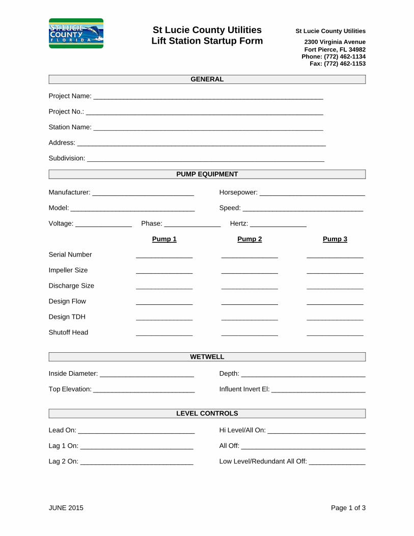
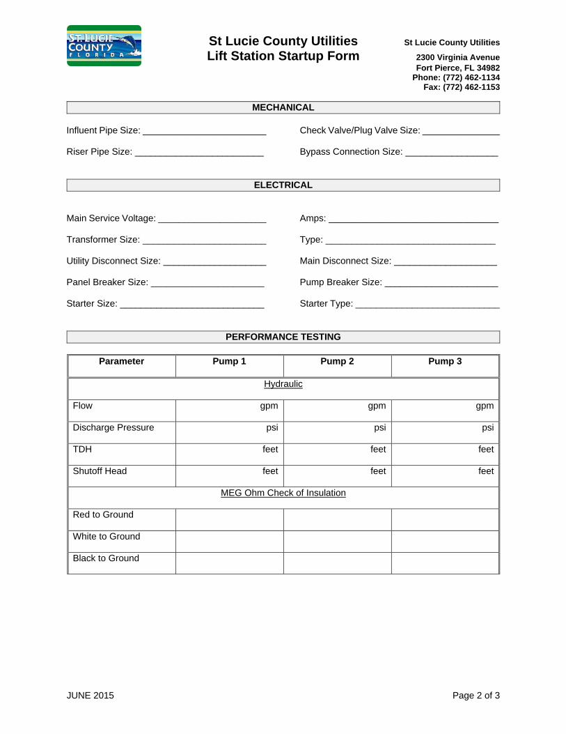
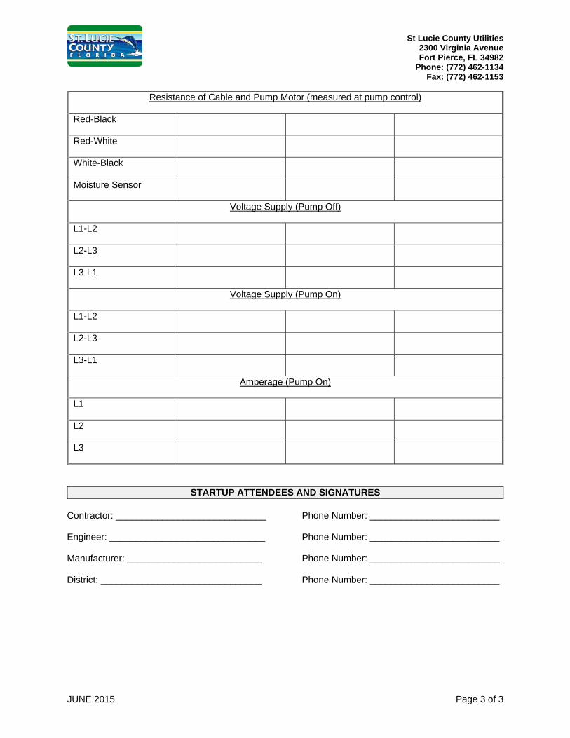
LIFT STATION STARTUP FORM
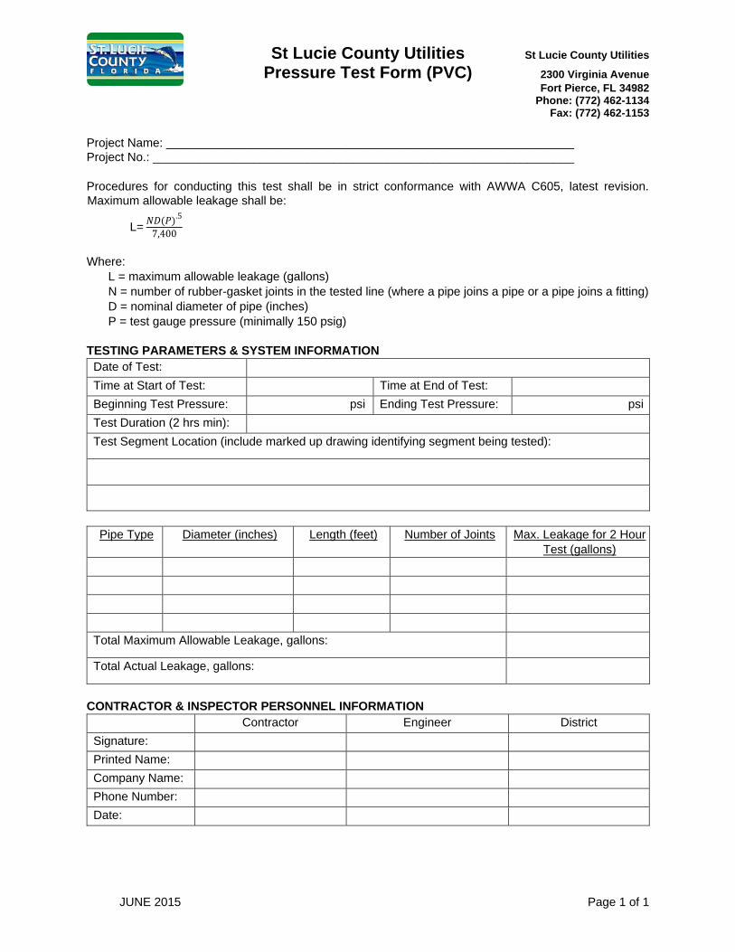
PRESSURE TEST FORM (PVC)
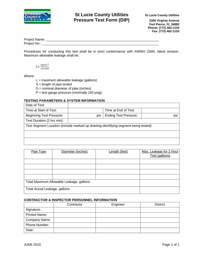
PRESSURE TEST FORM (DIP)
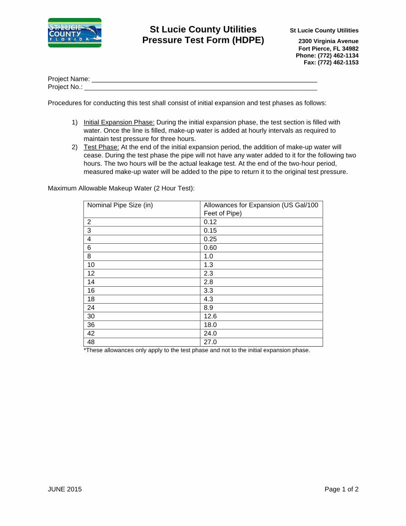
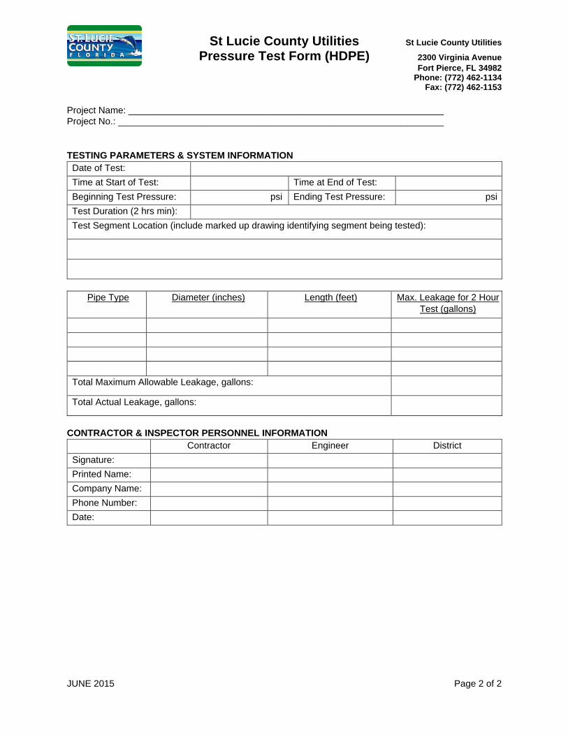
PRESSURE TEST FORM (HDPE)
LOW PRESSURE AIR TEST FORM
DESIGN CRITERIA
JUNE 2015 01100-1 DESIGN CRITERIA
SECTION 01100 GENERAL REQUIREMENTS AND DESIGN GUIDLINES
PART 1 – GENERAL 1.1 GENERAL REQUIREMENTS
A. These general design criteria are established for the design of water distribution, wastewater collection and reclaimed water systems in the jurisdiction of St. Lucie County Utilities (District). This portion of the document shall be used concurrently with the applicable sections of the Construction Standards and Technical Specifications.
B. All water distribution, wastewater collection and reclaimed water systems shall be
designed in accordance with the latest editions of the District standards and specifications, Florida Department of Environmental Protection (FDEP) requirements, "Recommended Standards for Water Works" and "Recommended Standards for Wastewater Facilities" established by the Great Lakes-Upper Mississippi River Board of State Public Health and Environmental Managers (Ten-State Standards), and all other federal, state, and local requirements.
C. Changes in the design made during the review process that were not requested by the
District shall be denoted by clouding on the plans and providing an explanation for the change in the body of the response to the Request for Additional Information.
D. All materials shall meet the minimum requirements in the Technical Specifications and be included in the Approved Materials List.
E. All horizontal and vertical survey control points shall be protected and undisturbed. In
the event that a control point is disturbed or destroyed the point shall be re-established by a registered Florida land surveyor at the expense of the Contractor.
F. The Contractor shall repair or replace any damage caused by construction activity to a
condition equal to or better than existed prior to construction.
1.2 REQUIRED MEETINGS
A. Preliminary Application Meeting between the Developer, Developer’s Engineer-of-Record, and District Staff to discuss the overall water, wastewater, and reclaimed water needs of the proposed development and review the availability of service.
B. Plan Review Meeting to discuss the review comments provided by the District and any possible offsite water, wastewater, and/or reclaimed water improvements that may be required.
C. A pre-construction meeting between the Developer’s Engineer-of-Record, the Contractor, the Utility Contractor (subcontractor), a District representative and, when appropriate, representatives of Florida Department of Transportation (FDOT) and/or the St. Lucie County Engineering Department must be held prior to construction.
JUNE 2015 01100-2 DESIGN CRITERIA
1.3 SUBMITTAL REQUIREMENTS
A. The following minimum information shall be submitted to the District for review and approval prior to the start of construction: 1. Four copies of the signed and sealed Construction Drawings meeting the minimum
requirements specified in Paragraph 1.4.
2. Two copies of the signed and sealed lift station calculations including design flows, force main sizing calculations, system curves with selected pump characteristic curves overlaid, buoyancy calculations, and cycle time calculations.
3. Two copies of the signed and sealed hydraulic analysis of the water and wastewater
distribution, transmission and collection systems including a fire flow analysis. Network modeling of pressure pipe systems shall be provided using WaterCAD or SewerCAD by Bentley, Inc. Version 8i, or latest version, or equivalent hydraulic modeling software as approved by the District. Submittals shall include copies of the input and output data for each scenario and full size (22”x34” or 24"x36") plots of each scenario showing a scale layout of the project including annotated lots, road right-of-ways (ROW) and names, phase lines, multifamily and commercial/industrial use boundaries and proposed equivalent residential connections, color coded and annotated pipe sizes and pressure contours, nodes and node numbers, legend, north arrow, scale, scenario description and date. Scenarios shall include but not be limited to average daily flow, average daily demand, maximum daily demand plus fire flow, peak hour demand, and peak hour flow. Two copies of the modeling file(s) shall be submitted on CD or DVD.
4. Two copies of the preliminary FDEP forms.
5. Two copies of the signed and sealed construction cost estimate.
6. Approval from the Fire Marshall of the fire protection system.
B. The following shall be submitted to the District a minimum of 10 days prior to the Pre-
construction Meeting: 1. Three sets of shop drawings for all materials used in construction.
2. A list of all required Contractor experience references.
C. Three copies of the Certification Package containing the applicable information below
shall be submitted to the District for review after the completion of construction and prior to the placement of water distribution, wastewater collection and reclaimed water facilities into operation:
JUNE 2015 01100-3 DESIGN CRITERIA
1. Draft Record Documents meeting the minimum standards specified in Paragraph1.05.
2. Approved Hydrostatic Pressure Test Reports witnessed and signed by a Districtrepresentative.
3. Successful bacteriological test results.
4. Approved Pigging Reports witnessed and signed by a District representative.
5. Gravity sewer televising and mandrel test results witnessed by a Districtrepresentative.
6. Density testing results from an approved laboratory.
7. New Lift Station Startup Completion Form.
8. Directional drilling completion documentation.
9. High Density Polyethylene (HDPE) pipe joint fusion inspection records.
10. FDEP request for clearance forms.
11. Operation and Maintenance manuals.
D. Upon approval of the Certification Package by the District and prior to the placement of the water distribution, wastewater collection and reclaimed water facilities into operation the following shall be submitted to the District:
1. Four copies of the final signed and sealed Record Documents.
2. Two copies of the FDEP clearance certification.
1.4 CONSTRUCTION DRAWING REQUIREMENTS
A. Water distribution, wastewater collection and reclaimed water construction drawings submitted to the District shall include the following minimum standards:
1. Prepare plans on full-sized sheets (22”x34” or 24”x36”). Three sets are to besubmitted initially for review. After District approval three sets and three CDs orDVDs of the PDF and AutoCAD files shall be submitted to the District. The plansshall be signed and sealed by a professional engineer licensed by the State ofFlorida.
2. Construction drawings shall be in AutoCAD 2012 or later.
JUNE 2015 01100-4 DESIGN CRITERIA
3. All plan sheets shall be to scale with the scale clearly noted and a graphic scale provided on each drawing.
4. All plan sheets shall have an arrow indicating the direction north (pointing up or to
the right).
5. A Cover Sheet that includes the project title, name of the developer, name of the engineering firm, a project location map with nearby and/or adjacent streets labeled, and a drawing index.
6. A legible Utility Master Site Plan clearly depicting the water, wastewater, and
reclaimed water systems. All phases of construction shall be clearly shown. The Utility Master Site Plan shall be a 1” = 40’ scale. If the entire project area does not fit on one sheet multiple sheets shall be used and a separate Key Map provided. Each Utility Master Site Plan sheet shall contain the key map in a corner (if applicable) with the particular sheet identified.
7. Plan and Profile Sheets shall be provided for all utilities. Mandatory Plan and Profile Sheets shall be drawn at 1” = 20’ or 1” = 30’ horizontal scale, and 1” = 2’ to 1” = 5’ vertical scale. Each Plan and Profile Sheet shall display the plan view above the profile view, and each shall depict the same length of utility installation. The plan shall be aligned vertically with the profile. If the entire project area does not fit on one sheet at these scales, then it shall be printed on multiple sheets, with a key map provided on each sheet indicating the location of the related sheet within the project.
8. The Plan and Profile Sheet plan view shall show all water mains, valves, fittings,
fire hydrants, services, meters, blow-off assemblies, wastewater mains, manholes, wyes, laterals, cleanouts, reclaimed water mains, storm water lines, electric lines, gas lines, paving, curbs and gutters, ROW lines, property lines, and all existing and proposed features.
9. The Plan and Profile Sheet profile view shall show the existing and proposed
finished grade over proposed and existing gravity wastewater mains. All wastewater gravity lines and wastewater force mains shall be shown in profile view. All stormwater lines in close proximity to depicted wastewater, water, and reclaimed water mains shall also be shown in profile view. All crossings (stormwater, wastewater, reclaimed water, and water mains) and all additional relevant utility information shall be included.
10. A Master Drainage Plan showing the stormwater facilities, including the 100-year
floodplain elevation, wetlands, creeks and adjacent floodplains, with elevations, shall be included for review. Wetlands, creeks, ponds, and any other water body shall be clearly delineated.
11. Landscape Plans shall show existing and proposed tree locations and species, and
shall include all potable water, reclaimed water, and wastewater utilities, shown
JUNE 2015 01100-5 DESIGN CRITERIA
clearly, without labeling.
12. Irrigation Plans including pumping facilities, storage reservoirs, mains, valves, controllers, individual lot irrigation systems, and irrigation schedules.
13. Utility Space Allocation Cross-sections for each different roadway section and
utility easement shall be included. Wastewater clean-outs, potable and reclaimed water meters shall be shown. Proposed trees shall be depicted on the utility allocations, including those within 20 feet of all ROW lines.
14. All materials shown on the plans shall be clearly labeled (i.e. pipe, valves, fire
hydrants, fire sprinkler lines, water meters, backflow preventers, fittings, manholes, services, and clean outs) with associated elevations, sizes, types, material, slopes, and appurtenances. Materials shall be labeled on each sheet on which the materials are shown.
15. All wastewater design information (pipe sizes, lengths, materials, slopes, manhole
top and invert elevations, and cleanout top and invert elevations) shall be shown. All existing wastewater service stub-outs to subject parcels are to be included in the drawings. Presentation of manhole information is recommended to be in a “Sanitary Sewer Structures Schedule” format, but in any case, must be shown on all sheets where manhole is drawn.
16. Elevations (manhole and cleanout tops and inverts) and pipe sizes of all existing
wastewater facilities that cross and/or are adjacent to the property.
17. The design drawings shall indicate any required grease, oil, sand, or lint separators and/or other pre-treatment systems required as part of the wastewater system.
18. All existing and proposed utility easements shall be shown with dimensions.
19. Connections to existing utilities. Locate, show, and label existing utilities that
cross or are adjacent to the property or project construction area.
20. All applicable Utility Construction Notes identified in the Construction Standards shall be included.
21. To facilitate incorporation of the facilities’ data shown on the Construction
Drawings into the District’s Geographic Information System (GIS), and to provide information that will allow the District to perform locates for buried facilities, a Boundary/Topographic Survey shall be provided that contains the following information:
a. Horizontal Coordinates
JUNE 2015 01100-6 DESIGN CRITERIA
(1) Construction Drawings shall be referenced to at least three points on the drawing that have noted horizontal coordinate information. These three points may be either existing control, new control, or parcel corners. As long as the drawing has a 1:1 relationship with these three points, the remainder of the drawing can be in a project coordinate system.
(2) The coordinate system for all record drawings shall be Florida State Plane Coordinates, North American Datum (NAD) 83 Zone East US Survey feet.
b. Vertical Coordinates
(1) All elevations provided shall be referenced to the North American Vertical Datum (NAVD) 88 datum with elevations given in US Survey feet.
c. Survey Information d. Surveyor Name
e. Survey Company
f. Date Surveyed
g. Control Reference Used (Control ID, Type, Coordinate Datum)
h. Control Type (PK nail, Brass Marker, etc)
22. Provide all applicable Standard Details.
23. Provide details for all connections to existing facilities.
24. Clearly show project phase lines if applicable.
25. Call out interferences with conflicting pipes with indication of “over” or “under” as
appropriate.
26. All road crossing and pavement cuttings and restorations shall be detailed and shall be in accordance with requirements of the particular authority governing the area.
1.5 RECORD DOCUMENT REQUIREMENTS
A. Record Drawing Requirements: 1. Record Drawings shall be prepared on full-sized sheets (22”x34” or 24”x36). Three
JUNE 2015 01100-7 DESIGN CRITERIA
sets are to be submitted initially for review. After District approval three sets and three CDs or DVDs of the PDF and AutoCAD files shall be submitted to the District.
2. Record Drawings shall be signed and sealed by the engineer licensed in the State of Florida in responsible charge of construction in accordance with Section 61G15-30.002(9) Florida Administrative Code (F.A.C.)
3. Record Drawings shall include the following minimum information:
a. The horizontal and vertical location of the mains and appurtenances shall be accurately depicted to scale and shall be identified relative to the baseline and relative to readily identifiable permanent reference points existing after the completion of the construction.
b. Horizontal location (coordinates and distance from permanent surface
improvements – e.g. edge-of-pavement) and vertical elevations (top-of-pipe and finished grade) for all for all mains at all high and low points, at the end points of each pipe segment, and at intervals not to exceed 100 feet.
c. Horizontal location (coordinates and distance from permanent surface
improvements – e.g. edge-of-pavement) and vertical elevations for all fittings, valves, hydrants, manholes, sample points, air releases, cleanouts, meters, etc.
d. Underground facilities (i.e. drainage, gas, electric, telephone, etc.)
crossing the mains shall be accurately shown both horizontally (coordinates and distance from permanent surface improvements – e.g. edge-of-pavement) and vertically and shall identify size, type, facility, material, and clearance.
e. Dimensions between manholes, slope of gravity mains, invert and top
elevations shall be shown.
f. Size, material, type, and pressure class of pipe.
g. Size and type of valves.
h. All deviations from the approved Construction Drawings. B. As-Built Survey Requirements:
1. An As-Built or Record Survey performed in accordance with Chapter 5J-17, F.A.C.,
pursuant to Chapter 472, Florida Statutes (F.S.) shall be required.
JUNE 2015 01100-8 DESIGN CRITERIA
2. The survey shall depict all pertinent easement lines, right of way lines or boundary lines as well as the horizontal and vertical location of all underground and above ground water, wastewater and reclaimed water piping and related appurtenances. The piping shall be shown at intervals not to exceed 100 feet. Sufficient “spot” elevations shall be shown in order to determine grading over and adjacent to the piping as well as the amount of cover over the piping. For lift stations: horizontal and vertical locations of the center top and invert of the wet well as well as horizontal and vertical locations of all at grade concrete and sufficient “spot elevations” to be able determine the drainage pattern within and adjacent to the lift station easement or tract. All existing fencing around lift stations shall be horizontally located with the type of fencing and height of fencing stated. In the event that fee simple title is conveyed to the District for a lift station or other facility a Boundary Survey shall be required in addition to the As-Built Survey.
C. Geodatabase Requirements:
1. Asset data of all installed assets shall be provided in an acceptable geodatabase,
comma delineated, or other file format approved by the District. The asset data shall include the following minimum information: a. X (Easting) and Y (Northing) in Florida State Plane Coordinates, NAD 83
Zone East. b. Z (Elevation) in NAVD 88 datum.
c. Utility Type (Potable Water, Wastewater, Reclaimed Water, and Raw
Water) d. Feature Type (Gate Valve, 45 Bend, Meter, Manhole, Hydrant, Blowoff,
ARV, Point on Line, etc.)
e. Diameter.
f. Year Installed.
g. Material Type (DR 18 C900, PC 350 CLDIP, PC 350 ELDIP, DR11 HDPE, etc.)
1.6 EASEMENTS
A. General
1. Easements for water, reclaimed, and wastewater mains and appurtenances shall be
provided when the water, reclaimed, and wastewater facilities are installed outside of road rights-of-way under St. Lucie County control. The easements may be either shown on the plat or granted to the County by a separate easement deed. The
JUNE 2015 01100-9 DESIGN CRITERIA
description for the easement shall be supplied by the Developer's Engineer or Surveyor and indicated on the record drawings (OR Book and Page No). In lieu of an easement over a specific portion or portions of the Property, a blanket easement may be provided by the Owner of the land. Easements shall be in a form acceptable to the County.
2. Easements shall be identified as unobstructed. Landscaping, other than grass, is considered an obstruction.
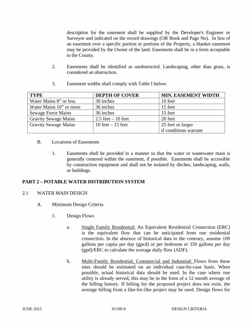
3. Easement widths shall comply with Table I below:
TYPE DEPTH OF COVER MIN. EASEMENT WIDTH Water Mains 8” or less 30 inches 10 feet Water Mains 10” or more 36 inches 15 feet Sewage Force Mains 36 inches 15 feet Gravity Sewage Mains 2.5 feet – 10 feet 20 feet Gravity Sewage Mains 10 feet – 15 feet 25 feet or larger
if conditions warrant
B. Locations of Easements
1. Easements shall be provided in a manner so that the water or wastewater main is generally centered within the easement, if possible. Easements shall be accessible by construction equipment and shall not be isolated by ditches, landscaping, walls, or buildings.
PART 2 – POTABLE WATER DISTRIBUTION SYSTEM 2.1 WATER MAIN DESIGN
A. Minimum Design Criteria
1. Design Flows a. Single Family Residential: An Equivalent Residential Connection (ERC)
is the equivalent flow that can be anticipated from one residential connection. In the absence of historical data to the contrary, assume 100 gallons per capita per day (gpcd) or per bedroom or 350 gallons per day (gpd)/ERC to calculate the average daily flow (ADF).
b. Multi-Family Residential, Commercial and Industrial: Flows from these sites should be estimated on an individual case-by-case basis. When possible, actual historical data should be used. In the case where one utility is already served, this may be in the form of a 12 month average of the billing history. If billing for the proposed project does not exist, the average billing from a like-for-like project may be used. Design flows for
JUNE 2015 01100-10 DESIGN CRITERIA
new water distribution systems may be based upon Table 1 of the State of Florida Department of Health (FDOH), Chapter 64E-6.08 F.A.C., Standards for Onsite Sewage Treatment and Disposal Systems or other approvable method where historical data is not available.
2. Minimum system size shall be based on the greater of a hydraulic analysis of the
following scenarios:
a. Maximum Day Demand (MDD) plus fire flow requirements while maintaining a minimum 20 psi residual pressure throughout the distribution system.
b. Peak Hour Demand (PHD) while maintaining a minimum 30 psi residual
pressure throughout the distribution system.
MDD and PHD and method of computation shall be subject to review and approval by the District but in no case may be less than as follows: MDD = Average Day Demand * 2.0 PHD = Average Day Demand * 4.0
3. Minimum pipe diameter allowed shall be 6 inches within looped systems and 8
inches on dead-ends, unless otherwise approved by the District.
B. Fire Flow Requirements
1. The following fire suppression water flow is the minimum for the specified use:
a. Residential Single family homes/duplexes 500 gpm Multi-family 2 story (12 or less units) 1,000 gpm Multi-family 2 story (greater than 12 units) 1,500 gpm b. Mercantile/business 3,000 sq. ft or less 750 gpm 3,000 – 15,000 sq. ft 1,000 gpm Greater than 15,000 sq. ft 1,500 gpm c. Industrial Less than 7,000 sq. ft 750 gpm Greater than 7,000 sq. ft 1,500 gpm d. Warehouse/storage Less than 7,000 sq. ft 750 gpm Greater than 7,000 sq. ft 1,500 gpm
JUNE 2015 01100-11 DESIGN CRITERIA
These are the minimum requirements for the specified uses within a minimum residual pressure of 20 psi. Additional water flow may be required to supplement fire sprinkler systems or to support other hazardous uses. The developer is responsible to meet any additional flow requirement beyond that which is within the capacity of the utility provider. [National Fire Protection Association (NFPA) 1 and NFPA 101].
C. Water Main Locations
1. Location within ROW
a. Water mains shall be no less than five feet from the edge of roadway
improvements, such as edge of pavement or back of curb/gutter. Where practical and consistent with other main locations in the area, water mains shall be located on the north side of east-west streets and on the east side of north-south streets. Placement of mains on or adjacent to interior property lines or on private property is discouraged, and will only be approved when unavoidable or when necessary for looping and when sufficient easements are provided to the operation and maintenance entity.
2. Horizontal and Vertical Separation
a. For parallel installations, water mains shall be laid with a minimum of 10
feet horizontal separation, edge-of-main to edge-of-main, from existing and proposed sewers.
b. For water mains crossing sewers, a minimum of 18 inches shall be
maintained from the outside of the water main to outside of the sewer main. At the crossing, one full- length joint of water main shall be laid in such a way that both joints will be as far from the sewer as possible. Sanitary sewers, force mains and storm sewers should cross under water mains, wherever possible.
c. Where it is not practical to design for these separations, specific
requirements from the regulatory agencies must be followed.
d. Horizontal separations of 15 feet to buildings, trees, top-of-banks of lakes and canals and other structures shall be maintained.
3. Dead Ends
a. Dead ends shall occur only when absolutely necessary and be equipped
with a blow-off device or fire hydrant for flushing purposes. All mains that dead end and that are intended for future expansion shall include a line size valve and blow-off. The gate valve shall be mechanically restrained in accordance with applicable construction standards. The
JUNE 2015 01100-12 DESIGN CRITERIA
blow-off must be designed to be removed without interruption to service. Blow-off devices shall be sized to provide a minimum of 2.5 feet per second flushing velocity in the water main.
4. Mechanical Restraint Requirements
a. Pipelines shall be restrained at all valves, bends, tees, crosses and dead ends.
This distance shall be determined by the Design Engineer in accordance with specific conditions/circumstances on each pipeline design project but in no case shall be less than the restrained length distance specified in the Construction Standards. Determination of distances shall occur during design and be specified within the Construction Drawings.
b. Mechanical restraint devices and specified length of restrained pipe shall be
as specified in UNI-Bell PVC Pipe Association specification "UNI-B-13" for PVC Pipe and the Ductile Iron Pipe Research Association "Thrust Restraint Design”, for Ductile Iron Pipe (DIP).
2.2 VALVES
A. General
1. All distribution systems shall be valved to facilitate the isolation of each section of pipeline between intersections of the grid system. Generally, the number of valves at an intersection shall be one less than the number of pipes forming the intersection. It is the intent of this criteria to provide for the isolation of mains that serve areas containing more than twenty-five service connections.
B. Spacing
1. Valves shall generally be spaced no more than 800 feet apart. In high-density
areas, valves shall be installed as necessary to minimize the number of persons affected by a break.
2.3 FIRE HYDRANTS
A. Spacing and Location
1. Fire hydrants shall be provided at each street intersection within the distribution system and at intermediate points that will provide a maximum 600 foot spacing between each hydrant in all water mains, transmission and distribution systems, or in accordance with local fire ordinance and state Insurance Services Office whichever is more stringent. A Fire Marshall approved plan is required with all preliminary plan submissions.
JUNE 2015 01100-13 DESIGN CRITERIA
2. Location of fire hydrants shall be at least one foot from ROW/property line and within 15 feet from edge of pavement, face of curb, etc. (except as required by FDOT), no less than five feet from driveways and/or back of curb and not within the swale/ditch or sidewalk area. Hydrants shall be located so as to minimize vulnerability to traffic. When placed within five feet of the edge of the street or paved area without raised curbs, the hydrant shall be protected from damage by the installation of 4” X 6’ concrete filled steel posts set three feet in to 12 inch diameter concrete filled holes.
B. Flow Requirements
1. Each fire hydrant shall be capable of delivering the specified flow and residual
pressures. 2.4 AIR RELIEF A. At points in the water main profile where entrapped air can accumulate, which may result in
flow blockage, provisions shall be made to remove the air. This shall be accomplished in distribution systems by use of strategically placed fire hydrants or blow-offs. In general, air relief assemblies shall only be used at aerial crossings and other similar circumstances.
2.5 WATER SERVICE CONNECTIONS AND METERS B. Spacing and Length
1. Individual service taps shall not be placed closer than 18 inches apart. A minimum of 18 inches must be maintained from all water main joints and appurtenances. Individual service taps shall be constructed with double strap saddles and corporation stops. Services shall not exceed 100 feet in length to the meter with the meter generally placed at the property line, at an accessible location. Services shall have a minimum of 30 inches cover including through ditches. All services crossing under roadways shall be installed in a casing, unless otherwise approved by the governing agency, with not less than 36 inches between the pavement and the top of the casing.
C. Meters
1. Proper sizing of non-residential meters and services is the responsibility of the Developer or his Engineer subject to District approval. Dual metering of a single building service (i.e. two one-inch meters instead of one two-inch meter) shall not be permitted. Construction drawings shall include a typical meter installation for each meter to be installed. Standard piping configurations for all size meters are found in the Construction Standards. Meters three inches and larger shall be installed above ground. The backflow prevention device shall be installed above ground, close to the meter on the customer side. No taps or connections are allowed between the meter and the backflow prevention device. Meters shall be set in grassy
JUNE 2015 01100-14 DESIGN CRITERIA
unobstructed areas generally at property lines, clear from buildings, fences, shrubs, trees, fire hydrants, cable boxes, etc. Meter boxes shall be kept out of pedestrian walkways and out of driveway areas or other concrete/paved surface, unless approved by the District.
D. Residential Meters
1. Meter size shall be as required by the District for single residences. Meters and boxes shall be provided and installed by the District in accordance with District connection requirements. For water main construction in front of vacant lots, service lines shall be installed from the main to property line with a magnetic marker identifying the location of the end of the service. Service lines for existing residences shall be provided with a meter box installed at the end of the service in accordance with the standard construction details.
2.6 SURFACE WATER CROSSINGS
A. For aerial or sub-aqueous crossing approvals, the District should be consulted before final plans are provided for review.
B. Aerial Crossings
1. All pipelines must be adequately supported on an acceptable foundation/support. The foundation/support design shall be signed and sealed by an engineer registered in the State of Florida. The installation must be protected from damage and must be accessible for repair or replacement. Valves and air relief valves should be placed at both ends of the water crossing, at the normal main depth, so that section of main can be isolated.
C. Sub-aqueous Crossings
1. A minimum of three feet, or as established by the regulatory agency, whichever is
greater, shall be maintained from the top of the water main to the design bottom elevation of the open canal/ditch. Sub-aqueous pipe crossings shall be made of DIP. For canal/ditches greater than 15 feet in width the water main shall be designed with flexible, watertight joints. Valves should be installed at each end of the sub-aqueous crossing so that the sub-aqueous section of the water main can be isolated. Valves shall be easily accessible.
2.7 BACKFLOW PREVENTION/CROSS CONNECTION CONTROL
A. There shall be no physical connection between a safe water supply and a questionable water supply, a reclaimed water supply, or a sanitary or storm sewage system that would allow unsafe water to enter the safe water system by direct pressure, vacuum gravity or any other means. All potable water services within wastewater facilities shall be provided with an approved backflow-preventing device.
JUNE 2015 01100-15 DESIGN CRITERIA
B. The developer shall comply with the requirements of the District Cross-Connection Control
Program. 2.8 CONNECTIONS TO EXISTING SYSTEM
A. Connections to existing system shall be made by tapping sleeves, cut-in tees, or existing stub-outs. Each connection to an existing system shall include an isolation valve.
B. Size on Size Taps
1. Taps may be made on the same size main only when the main to be tapped is
AWWA C900, C905 or DIP. PART 3 – WASTEWATER COLLECTION 3.1 GRAVITY SEWER DESIGN
A. Minimum Design Criteria
1. Wastewater design shall be based on an average flow of not less than 100 gallons per capita per day of sewage flow for the estimated ultimate tributary population. Similarly for institutional, commercial, industrial parks, etc.; sewer systems shall be designed for the ultimate/buildout sewage flow. This may be estimated from existing records for similar developments. Average daily flow will then be adjusted with the appropriate design peak factors for lateral and trunk lines, which is to be based on factors outlined within the Ten-State Standards.
B. Pretreatment
1. All developments where foods will be prepared, processed or served shall have a
grease trap of adequate capacity with solids retention device installed through which the wastewater from the preparation area shall pass prior to entering the sanitary sewer system.
2. All developments producing industrial wastes shall have the appropriate onsite pre-treatment systems approved by the District and be subject to the St. Lucie County Industrial Pretreatment Program.
C. Diameter and Slope
1. The minimum allowable diameter for gravity sewer systems shall be 8 inches and
more specifically sized to accommodate the flows as outlined under 3.01-A-1.
2. Slope: Gravity sewer mains shall maintain hydraulic slopes sufficient to maintain a minimum velocity of 2.0 feet per second, based on Manning's formula using an "N"
JUNE 2015 01100-16 DESIGN CRITERIA
value of 0.013, when flowing full or half full. As a guideline the following minimum slopes shall be provided; however, slopes greater than these are desirable. Installations where velocities of 15 feet per second are proposed, due to topography or other unique circumstances, main and appurtenances must be protected against displacement and impact.
D. Ratio of Depth of Flow to Pipe Diameter (dn/D) 1. New sewer mains 15 inches and smaller in diameter shall be sized to carry the
projected peak wet weather flow at a depth not greater than half of the inside diameter of the pipe (dn/D not to exceed 0.5). New sewer mains 18 inches and larger shall be sized to carry the projected peak wet weather flow at a depth of flow not greater than 3/4 of the inside diameter of the pipe (dn/D not to exceed 0.75).
E. Alignment
1. Gravity sewer mains shall be designed and constructed in straight alignments with
uniform slope. Straight alignment shall be checked by either using a laser beam, lamping or other approved method.
2. Gravity sewer mains of different diameters shall connect at a sewer manhole. The invert of the larger main shall be lowered sufficiently below the smaller main to maintain the same energy gradient.
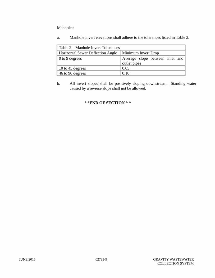
3. Gravity sewer main direction changes, within a sewer manhole, cannot exceed 90 degrees. Flow direction changes in excess of 45 degrees shall include an extra 0.1 feet of drop across the inflow and outflow of the manhole.
4. Drop manholes shall be installed when the invert of the influent pipe is greater than 2.0 feet above the outgoing invert of the manhole. Where the difference in inverts is equal to or less than 2.0 feet, the invert across the manholes shall be grouted to prevent deposition of solids.
5. All gravity sewer mains shall terminate at sewer manholes.
JUNE 2015 01100-17 DESIGN CRITERIA
6. Horizontal separation from water mains shall be ten feet. Separation from reclaimed water mains shall be five feet. Vertical separation from a water main shall be a minimum of 18 inches between the outside of the pipes. Sanitary sewers and force mains should cross under water mains. Reference Part 2 of this section for additional requirements related to separation of water and sewer piping.
F. Pipe Materials
1. All gravity sewer mains shall be designed to prevent damage from all anticipated live and dead loads. Where necessary, as determined by the Engineer, special bedding, haunching and initial backfill or other special construction methods will be required.
3.2 MANHOLES
A. Location
1. Manholes shall be installed at the termination of all gravity sewer mains, grade breaks, changes in the sewer main diameter, changes in alignment and at distances not exceeding 400 feet.
2. Manholes shall be placed in accessible paved areas flush with finished grade.
Manholes may only be placed outside of hardened surfaces with written approval from the District and shall have a rim elevation a minimum of 6 inches above finished grade with a 10:1 slope back to finished grade.
3. Manholes shall not be placed in low lying areas where storm water infiltration may occur.
B. Size and Depth
1. The minimum inside diameter of sanitary sewer manholes shall be four feet and
have a minimum top opening of two feet. The minimum depth of manholes shall be four feet from the finished grade to invert of the manhole. If DIP gravity sewer main is used, minimum depth can be three feet with approval of the District.
JUNE 2015 01100-18 DESIGN CRITERIA
PART 4 – FORCE MAINS 4.1 FORCE MAIN DESIGN
A. Minimum Design Criteria
1. Force mains shall not be less than four-inch diameter and have a minimum design velocity of two feet per second. The main shall be sized to adequately handle the build-out peak operational pump flow of the wastewater lift station(s) serving particular areas. The requirements of sufficient scouring velocity, two feet per second, shall apply to the ultimate minimum operational pumping flow. Scouring velocities less than two feet per second, that are temporary, will be considered by the District under special circumstances provided provisions for pigging of the force main are provided.
B. General
1. All private force mains entering County or FDOT ROW shall be built to these minimum standards past the ROW line. A valve shall be placed at the ROW line to delineate the change in maintenance responsibilities. The District shall control said valve.
C. Location
1. Location within ROW: As a general guide, force mains shall be on the opposite
side of the ROW as water mains.
2. Force mains should be installed under water mains at crossings. Maintain a minimum vertical separation of 18 inches and a horizontal separation of 10’ between outside of pipes. Reference Part 2 of this section for additional requirements related to separation between sewer and water mains.
4.2 VALVES
A. Location of valves along subsidiary force mains shall generally be every 1,500 feet and at the point of connections to larger trunk mains. Where force mains are to be extended, a valve and restrained plug shall be installed at the future point of connection. In high density areas, valves shall be installed at closer intervals as necessary to minimize the number of persons affected by the break.
B. A valve shall be placed at the ROW line to delineate the change in maintenance
responsibilities. The District shall control said valve.
JUNE 2015 01100-19 DESIGN CRITERIA
4.3 TERMINATION
A. Force mains shall enter a termination wet well at a point equivalent to the operating level of the wet well. At a termination gravity manhole, the force main shall enter no higher than two feet above the flow line of the receiving manhole. Force mains shall never enter a manhole from a direction contrary to the direction of flow out of the manhole.
4.4 CONNECTIONS FOR FORCE MAINS
A. Connections to existing system shall be made by tapping sleeves, cut-in tees, or existing stub-outs. Each connection to an existing system shall include an isolation valve.
B. Size on Size Taps
1. Taps may be made on the same size main only when the main to be tapped is
AWWA C900, C905 or DIP. PART 5 – WASTEWATER PUMPING STATIONS 5.1 STATION DESIGN
A. Type
1. All pumping stations shall be of the below ground type using submersible wastewater pumps, unless otherwise justified and approved by the District.
2. All stations shall be designed for 230 volt or 460 volt, 3 phase electric service.
B. Pumps
1. Pumping stations shall have a minimum of two, equal capacity, submersible
pumps. When pumping rates exceed 1,000 gallons per minute (GPM), three or more pumps shall be required. Pumps shall be sized such that with any one pump off-line, then the remaining pump(s) can handle the design flow.
2. In projects constructed in phases, master lift stations that will have minimal flows for a considerable time shall be equipped with temporary pumps with reduced capacity (though not less than 50% of a permanent pump capacity) appropriately sized for the initial phases of the project. All lift station mechanical and electrical components shall be sized to accept the temporary and build-out pumps.
C. Design Flows
1. The pumping design flow (peak design flow) rate shall be the maximum
contiguous three month average daily flow multiplied by the appropriate peak
JUNE 2015 01100-20 DESIGN CRITERIA
hourly factor, as established by the Design Engineer and approved by the District, based on established standard engineering practices. The maximum contiguous three months average daily flow shall be from all contributory areas within the individual pumping station service area based on existing flows within the service area and anticipated flows through the next five years. Average daily flow figures shall be as specified within these standards.
2. All pumping units shall have the capacity to pump the peak design flow at the maximum computed system total dynamic head (TDH). This flow condition shall be coordinated for the proper force main sizing to ensure the minimum scouring velocities.
D. Wet Well Design
1. The minimum effective operational volume of the wet well (Lead Pump On to All
Pump Off levels) shall be sized based on the formula V=(Q*TC)/4 where: V = Minimum operation volume in gallons Q = Maximum pump capacity in GPM (capacity of the lead pump using
the minimum head operational scenario) TC = Cycle time in minutes (10 minutes shall be used).
2. Low water level shall be set to provide complete submergence of pumps at shut-off.
The high water alarm shall be set at the invert elevation of the lowest influent pipe.
3. Buoyancy calculations shall be performed that do not take into consideration the wet well interior fillets, top slab, pumps and piping. Ground water elevation shall be assumed at natural ground level, unless special circumstances dictate other assumptions.
4. Wet well top slab elevation and electrical components of the station shall be above
the 100-year flood elevation.
5. Submersible pumps shall be installed with guide rails, discharge connections, and lifting chains or lifting cables.
E. Electrical and Controls
1. All stations shall be designed for 230 volt or 460 volt, 3 phase electric service with
emergency power feed hookup. A non-fused main disconnect shall be provided.
2. Electrical fixtures within enclosed areas where gas may accumulate shall comply with the National Board of Fire Underwriter's specifications for hazardous conditions. Electrical fixtures/components at the station shall be sized for expansion of the pump and load. Pump control panel housing shall be NEMA type 4X, constructed of stainless steel (14 gauge, minimum).
JUNE 2015 01100-21 DESIGN CRITERIA
3. Pump level controls shall be float type switches. Float switches shall be located in such a way that they will not be influenced by incoming flows. High-level alarms shall be provided with all pump stations. The panel shall be equipped with a hard wired phone line and autodialer.
4. Control circuitry within the control panel will provide automatic alternation of each
pump during each cycle.
5. Each control panel shall have a main and emergency circuit breaker.
6. Unless permanent standby power is provided a generator power receptacle shall be provided on the exterior of the pump control panel on the side facing the gate. The receptacle shall be compatible with the District portable generators.
7. The lift station control panel shall be located to meet all applicable codes.
F. Standby Power
1. Lift stations serving more than 500 ERCs or receiving flow from one or more lift
stations shall be equipped with permanent standby power generation and automatic transfer switch.
G. Valves and Piping
1. Isolation valves and check valves shall be provided on the discharge of each
pump. A valve pit or vault shall be provided for access to the valves.
2. Discharge piping shall be a minimum of 4” in diameter.
H. Water Service
1. Each pumping station shall be provided with a minimum 1 ½-inch potable water supply. Each supply shall have a hose bibb and reduced pressure zone, backflow preventer.
I. Site Enclosures
1. All pumping stations shall be enclosed by chainlink fencing.
2. Easements and/or ROW of sufficient size shall be provided for vehicle access to
the station. An easement or deed for the lift station site will be required.
3. All pumping station sites shall be provided with minimum of 6-inch thick reinforced concrete slab within the fenced area and a minimum 6-inch reinforced concrete driveway and apron connected to a paved road that will allow routine
JUNE 2015 01100-22 DESIGN CRITERIA
access which will support all anticipated loads. Necessary driveway culverts shall also be provided in accordance with jurisdictional agency requirements.
4. Hinges for access hatches on both the pumping station top slab and valve pit shall be configured to allow both hatches to open outward or away from the other and toward the panel.
PART 6 – RECLAIMED WATER SYSTEMS 6.1 GENERAL REQUIREMENTS
The design and construction of reclaimed water facilities shall be based on the criteria outlined in Chapter 62-610 F.A.C. Supplemental specifications for individual components of the reclaimed water system will be provided by the District. The engineering report described in Rule 62.610.310 shall be submitted with each project. The abbreviated version described may be applicable. Users of reclaimed water shall execute with the Department a binding agreement ensuring that construction, operation, maintenance, and monitoring meets the requirements of 62-600, 62-610, and 62-620, F.A.C. Such binding agreements are required for all Reclaimed sites not owned by the permittee. The developer shall provide the Department plans, in addition to those of the meter station, a scale drawing of the site irrigation plan including pump facilities, storage reservoirs, mains, valves, controllers, individual lot irrigation systems, and irrigation schedules. Locations for the installation of Public Notification Signage shall be sited on the drawings with details of the standard. Use of reclaimed water through hoses, faucets, hose bibbs, or couplers is prohibited. Reclaimed water is prohibited inside buildings without prior written approval from the District.
6.2 RECLAIMED WATER MAIN DESIGN A. Basis for Design:
1. Initial projections of reclaimed water use for new developments shall be based on
the number of Equivalent Residential Connections (ERCs) represented by the development and historical data for average wastewater flow per ERC. Reclaimed water use commitments by the customers shall be estimated as 85 percent of potable water demand or 100 gpcd, whichever is greater.
2. In order to establish connection requirements and provide guidelines for use of
reclaimed water and construction of irrigation systems within developments on
JUNE 2015 01100-23 DESIGN CRITERIA
North Hutchinson Island, a Reclaimed Water Protocol was adopted by the District. The protocol describes procedures for notifying developers of required connections; establishes reclaimed water connection fees, rates charges and required usage; specifies requirements for private irrigation systems and design reports; addresses irrigation schedules; establishes inspection procedures; and describes penalties for noncompliance. This protocol shall be utilized as it applies to all developments on North Hutchinson Island.
A. Minimum Design Demand
1. The design daily water demand for a typical residential reclaimed water service shall be 600 gpd minimum. Reclaimed water mains shall be sized utilizing 5 gpm/residential units (at a minimum). This reclaimed water main design rate shall be used for all residents in the development which already takes into consideration the irrigation schedule. Multifamily residential, commercial and industrial flow demand shall be estimated on an individual case-by-case basis.
B. Pressure
1. All reclaimed water mains shall be sized after a hydraulic analysis based on flow demands and pressure requirements. The system shall be designed to maintain a minimum pressure of 30 psi at ground level at all points in the distribution system under all conditions of flow. The normal working pressure in the distribution system should be approximately 65 psi and not less than 40 psi.
B. Diameter
1. The minimum size of reclaimed water mains used as trunk systems shall be 6 inches. Where applicable, larger pipe shall be specified. Any departure from these minimum requirements shall be justified by hydraulic analysis and future reclaimed water demand, and must be approved by the District.
C. Location
1. Horizontal and Vertical Separation
a. Sanitary sewers, force mains, reclaimed water mains and storm sewers should cross under potable water mains whenever possible. Sanitary sewers, force mains, reclaimed water mains and storm sewers crossing water mains shall be in accordance with drawing G-5.
b. Horizontal separation of 15 feet to buildings, trees, top of banks of lakes and
canals, and other structures shall be maintained, if possible. An absolute minimum of 10 feet may be allowed only when unavoidable and only with DIP.
JUNE 2015 01100-24 DESIGN CRITERIA
D. Service Connections
1. There are two Customer Classifications established for the District North Hutchinson Island service areas.
a. Class ‘M’ customers: All wastewater customers who are required to connect
to the District reclaimed water system within 90 days of notification of availability by the District. Class ‘M’ customers shall agree to purchase and to use a volume of reclaimed water equal to the volume of wastewater discharged on a weekly, monthly or equivalent average basis.
b. Class ‘V’ customers: Class ‘V’ customers were connected to the District
wastewater collection system prior to the availability of reclaimed water in their area but have voluntarily connected to the District reclaimed water system. Class V customers shall not be required to use any minimum volumes of reclaimed water.
* * END OF SECTION * *
TECHNICAL SPECIFICATIONS
JUNE 2015 01210-1 INSPECTORS AUTHORITY
SECTION 01210 INSPECTORS AUTHORITY
PART 1 – GENERAL 1.1 GENERAL
A. District Inspectors may inspect all construction and materials and may also inspect preparation, fabrication or manufacture of components, materials and supplies. The Inspector is not authorized to revoke, alter or waive any requirements of the specifications, but is authorized and expected to call to the attention of the Developer’s Engineer-of-Record and/or Contractor any failure of work or materials to conform to the plans or specifications. The Inspector shall have the authority to reject materials or suspend the work until questions of issue can be referred to and decided upon by the District Director or his designated representative.
B. The Inspector shall in no case act as foreman or perform other duties for the Developer’s
Engineer-of-Record and/or Contractor nor interfere with the management of the work. Advice which the Inspector may give shall in no way be construed as binding to the District or releasing the Developer, his Engineer or Contractor from performing according to the intent of the plans and minimum District Standards.
C. All work that has been rejected or condemned shall be repaired, or if it cannot be
satisfactorily repaired, shall be removed and replaced at the Contractor/Developer’s expense. Materials not conforming to the requirements of the specifications shall be removed immediately from the site of work and replaced with satisfactory material by the Contractor/Developer, at his expense. The District shall have the right to require additional inspections, certification and/or testing to confirm that the deficient work has been corrected.
D. Inspections shall be scheduled for regular working hours only, except for nights when
service disruptions are involved. Scheduled inspections are required for jack and bores and pipe slippage through same, directional bores, setting of wet wells, lift station start-ups with manufacturer’s representative and Developer’s Engineer-of-Record present, and any time an existing District facility is to be connected (i.e. manhole tie-in and water or wastewater taps). Work will not be scheduled for weekends or holidays.
When progress of the project requires the periodic presence of a District Representative during non-normal working hours, for the convenience of the Contractor, the Contractor/Developer shall accept the financial responsibility for the overtime hours (at overtime rates) with a minimum of four hours, including travel time. This shall include work done on holidays, weekends, or other non-scheduled work hours.
E. The District should be provided with at least two full working days notice for scheduled inspections. Inspectors may make unscheduled visits as needed to inspect such items as materials on site and clearances between conflicting lines.
JUNE 2015 01210-2 INSPECTORS AUTHORITY
It shall be the responsibility of the Developer’s Engineer-of-Record to schedule inspections and their qualified representative shall be present at all scheduled tests and inspections. A scheduled inspection will be canceled if the representative is not present. The Developer’s Engineer-of-Record shall pre-test all required tests to minimize failures. The Developer’s professional land surveyor shall prepare accurate record drawings which shall be submitted to the District two days before a gravity line inspections to verify adequacy of slopes.
* * END OF SECTION * *
JUNE 2015 02200-1 EARTHWORK
02200 EARTHWORK
PART 1 – GENERAL 1.1 SECTION DESCRIPTION
A. The provisions set forth in this section shall be applicable to all underground water, reclaimed water and wastewater infrastructure installations.
B. This section includes materials, installation standards, and Contractor responsibilities
associated with the furnishing of all labor, materials, equipment and incidentals required to properly perform utility excavation backfilling and compacting for all utility infrastructure as shown on the drawings and as specified herein.
C. All excavations shall be properly shored, sheeted, and braced or cut back at the proper
slope to provide safe working conditions, to prevent shifting of material, to prevent damage to structures or other work, and to avoid delay to the work, all in compliance with the Occupational Safety and Health Act (OSHA), the State of Florida Trench Safety Act, and under Section 107 of the Contract Work Hours and Safety Standards Act.
1.2 SUBMITTALS
A. The Contractor shall obtain necessary permits for any required dewatering activity in accordance with the applicable governmental agencies. These permits (if required) shall be submitted to the District prior to the start of construction.
PART 2 – PRODUCTS 2.1 MATERIALS
A. Fill material shall be clean granular fine earth, rock or sand, and free of vegetation or
organic material.
B. Material may be from onsite excavation or may be imported. C. Suitable Materials for fills shall be classified as A-1, A-3, or A-2-4 in accordance with
American Association of State Highway and Transportation Officials (AASHTO) Designation M-145 and shall be free from vegetation and organic material. Not more than 12-percent by weight of fill material shall pass the No. 200 sieve.
D. Suitable material for fill to be placed in water shall be classified as A-1 or A-3 in
accordance with AASHTO Designation M-145.
JUNE 2015 02200-2 EARTHWORK
E. Unsuitable materials are classified as A-2-5, A-2-6, A-2-7, A-4, A-5, A-7, and A-8 in accordance with AASHTO Designation M-145 and soils which cannot be compacted to the specified percentage of maximum density.
PART 3 – EXECUTION 3.1 CLEARING, GRUBBING AND STRIPPING
A. Remove existing vegetation including trees, roots and stumps from the corridor areas. Prevent damage to trees or other items outside of the corridor area.
B. All vegetation material removed shall be disposed of properly by the Contractor.
3.2 GENERAL EXCAVATION
A. The maximum amount of open trench permitted in any one location shall be the length necessary to accommodate the amount of pipe installed in a single day. All trenches shall be fully backfilled and compacted at the end of the day. Barricades and warning lights meeting OSHA, the Florida Department of Transportation and the Uniform Manual of Traffic Control Devices requirements shall be provided and maintained.
B. Trench Dimensions
1. The minimum width of the trench shall be equal to the outside diameter of the infrastructure, plus the minimum width necessary to obtain proper utility infrastructure excavation backfill and compaction requirements; the maximum width of trench, measured at the top of the infrastructure, shall not exceed the outside infrastructure diameter plus two feet, unless otherwise approved by the District.
C. Trench Grade
1. Standard trench grade shall be defined as the bottom surface of the utility
infrastructure to be constructed or placed within the trench. Trench grade for utilities in rock or other non-cushioning material shall be defined as six inches below the outside bottom of the utility, which six inches shall be backfilled with extra Suitable Material. Excavation below trench grade that is done in error shall be backfilled to trench grade with Suitable Material and compacted as specified.
D. Utility Bedding
1. The bottom of the trench shall be shaped to provide a firm bedding for the utility
infrastructure. The utility shall be firmly bedded in undisturbed firm soil, or hand-shaped unyielding material. The bedding shall be shaped so that the infrastructure will be in continuous contact therewith for its full length and width and shall
JUNE 2015 02200-3 EARTHWORK
provide a minimum bottom segment support for the infrastructure or one-half of the outside diameter of the barrel of pipe.
E. Unsuitable Material Below Trench Grade
1. Soil unsuitable for a proper foundation encountered at or below trench grade, such
as muck or other deleterious material, shall be removed for the full width of the trench and to the depth required to reach suitable foundation material, unless special design considerations receive prior approval from the District. Backfilling below trench grade shall be in compliance with applicable provisions of Subsection 3.3, “Backfilling”, with Suitable Material.
F. Extra Utility-Bedding Material
1. When rock or other non-cushioning material is encountered at trench grade,
excavation shall be extended to six inches below the outside bottom of the utility, and a cushioning granular Suitable Material shall be provided. Utility-bedding material shall be installed as specified under Subsection 3.3, “Backfilling”.
G. Sheeting and Bracing 1. In order to prevent damage to property, injury to persons, erosion, cave-ins, or
excessive trench widths, adequate sheeting and bracing shall be provided, as required within these specifications, in accepted standard practice. When the situation arises, sheeting and bracing shall be used as necessary to protect the integrity of the road shoulder. Sheeting shall be removed when the trench has been backfilled to at least one-half its depth, or when removal would not endanger the construction of adjacent structures. When required, to eliminate excessive trench width or other damage, sheeting, bracing, or shoring shall be left in place and the top cut off at an elevation five feet below finished grade or one foot above the top of the infrastructure, whichever is less, unless otherwise approved by the District.
H. Excavated Material
1. Suitable Material to be used for backfill shall be neatly and safely deposited at the
sides of trenches where space is available. Whenever possible, excavated material near a roadway should be deposited on the right-of-way side of the trench away from the travelway. Where stockpiling of excavated material is required, the Contractor shall be responsible for obtaining the sites to be used and shall maintain the operation to provide for natural drainage and not present and unsightly appearance. In addition, the Contractor is responsible for transporting the material to and from the stockpile location. All sites shall be restored after fill is removed to a condition equal or better than existed prior to stockpiling. No excavated material shall be placed within roadside swales for longer than that day’s work.
JUNE 2015 02200-4 EARTHWORK
I. Excess Fill Material
1. Clean excess fill shall be the property of the District, should they request the
same. Otherwise, it will be the property of the Contractor to remove from the site. If requested by the District, the Contractor shall deliver and stockpile the excess fill material to areas within St. Lucie County designated by the District. Resale of excavated material on the project site will not be permitted.
J. Material Disposal
1. Unsuitable fill material or cleared and grubbed material resulting from the utility
installation shall be removed from the work site and properly disposed of at location(s) secured by the Contractor, and in accordance with the agency having jurisdiction.
K. Borrow
1. Should there be insufficient satisfactory material from the excavations to meet the
requirements for fill material, borrow shall be by the Contractor. All borrow shall meet the provisions of these specifications.
L. Rock Excavation
1. Rock excavation shall be defined as excavation of any hard natural substance
which cannot be removed by a one cubic yard bucket and requires the use of explosives and/or special impact tools such as jackhammers, sledges, chisels, or similar devices specifically designed for use in cutting or breaking rock.
M. Dewatering
1. Utilities shall be laid “in the dry”, unless otherwise approved in writing by the
District. All dewatering activities are to be performed by the Contractor. Trench excavations may be dewatered by using one or more of the following methods: well point system, sumps with pumps, or other methods as approved by the Developer’s Engineer-of-Record. Dewatering systems shall be used in accordance with good standard practice and must be sufficient enough to lower the water level in advance of the excavation and maintain it continuously to keep the trench bottom and sides firm and dry. If the material encountered at trench grade is suitable for the passage of water without destroying the sides or utility foundation of the trench, sumps may be provided at intervals at the side of the main trench excavation, with pumps used to lower the water level by taking their suction from said sumps. Discharge from dewatering shall be disposed of in such a manner that it will not interfere with the normal drainage of the area in which the work is performed, create a public nuisance, or form ponding. All discharge shall be in accordance with any South Florida Water Management District issued permits.
JUNE 2015 02200-5 EARTHWORK
The operations shall not cause injury to any portion of the work completed, or in progress, or to the surface of streets, or to private property. The proposed dewatering method(s) and schedule shall be approved by the Developer’s Engineer-of-Record and necessary regulatory agencies prior to construction. Additionally, where private property will be involved, advanced permission shall be obtained by the Contractor.
N. Obstructions
1. It shall be the Contractor’s responsibility to acquaint himself with existing
conditions and to locate structures and utilities along the proposed utility alignment in order to avoid conflicts. Where actual conflicts are unavoidable, work shall be coordinated with the facility owner and performed so as to cause as little interference as possible with the service rendered by the facility disturbed. All affected utilities shall be notified prior to excavation in their vicinity.
3.3 BACKFILLING
A. General 1. Backfill shall be Suitable Material as specified above. Backfilling shall be divided
into three specified areas: 1) Initial Backfill: from trench grade to a point 12 inches above the top of the utility, 2) Final Backfill: from the top of the Initial Backfill to the bottom of the subgrade, 3) Replacement Base Course: from the top of the Final Backfill to the replacement surface.
B. Initial Backfill
1. Granular material shall be carefully placed and tamped around the lower half
(springline) of the utility. Backfilling shall be carefully continued until the fill is 12 inches above the top of the utility in layers not exceeding six inches (uncompacted thickness), using the best available Suitable Material from the excavation, if approved.
The material shall be lowered to within two feet above the top of pipes before it is allowed to fall, unless the material is placed with approved devices that protect the pipes from impact. Initial backfill shall exclude stones, or rock fragments larger than ¾-inch. Each lift of Initial Backfill shall be compacted to 98% of maximum density as determined by AASHTO T-180.
C. Final Backfill
1. The remainder of the trench, above the initial backfill and below the subgrade,
shall be backfilled and compacted in layers not exceeding 12 inches (uncompacted thickness), except that the last two lifts shall not exceed six inches
JUNE 2015 02200-6 EARTHWORK
(uncompacted thickness) per lift. Compaction of each lift shall have a minimum compaction of 98% of maximum density as determined by AASHTO T-180.
D. Shoulder Restoration
1. All shoulder restoration shall be in accordance with the applicable permit
requirements of the agency having jurisdiction. E. Protective Concrete Slab
1. Protective concrete slabs shall be installed over the top of trenches, where
required, to protect the installed utility against excessive loads, or where insufficient cover exists.
3.4 COMPACTION
A. Compaction Methods 1. Specified compaction shall be accomplished using accepted standard methods
(powered tampers, vibrators, etc.), with the exception that the first 12 inches of backfilling over the pipe shall be compacted by hand-operated tamping devices. Flooding or puddling with water to consolidate backfill is not acceptable, except where sugar sand is encountered and the operation has been approved by the District and the Developer’s Engineer-of-Record.
B. Location of Density Tests
1. Density tests of trench backfill material shall be required at the trench bottom and
each lift of backfill at intervals of not more than 500 feet. Density tests of pavement open-cut areas, including roads, turn lanes, and drives shall be required at intervals of not more than 50 feet.
C. Density Tests
1. Density tests for determination of the above-specified compaction shall be made
by a qualified testing laboratory. If any tests are unsatisfactory, the Contractor shall re-excavate, re-compact the backfill, and retest, at his expense until the specified compaction is obtained. Additional compaction tests shall be made to each side of an unsatisfactory test, as directed, to determine the extent of re-excavation and re-compaction necessary. All tests shall be submitted to the District for their records.
* * END OF SECTION * *
JUNE 2015 02310-1 JACK AND BORE
SECTION 02310 JACK AND BORE
PART 1 – GENERAL
1.1 SECTION DESCRIPTION
A. This section includes materials, performance and installation standards associated with the furnishing of all labor, materials, equipment and incidentals required to install, boring and jacking installations complete.
PART 2 – PRODUCTS
2.1 CASING PIPE MATERIALS AND INSTALLATION
A. Casings shall be steel pipe conforming to the requirements of American Society for Testing and Materials (ASTM) Designation A-139. The minimum casing pipe size and wall thickness shall be as shown on the drawings. For sizes not included therein, or for special design considerations, approval shall be obtained from the Developer’s Engineer-of-Record.
B. For crossing of state roads, or under railroad right-of-way, casing materials and installation shall conform to FDOT or Railroad Standards.
2.2 CARRIER PIPES
A. Wastewater and water carrier pipes to be installed within the specified casings shall be equipped with restrained joint connections. Pipe and fittings shall comply with the applicable provisions of these Standards, with minimum Ductile Iron Pipe Class 51.
2.3 CASING SPACERS
A. Non-corrosive casing insulators shall be used. The casing runner height shall be large enough so that it does not interfere with the pipe restrained joints. Stainless steel nuts and bolts shall be used. Installation and spacing of casing insulators shall be as required by the manufacturer, and as shown on the standard construction details.
B. Casing spacers shall be two-piece T-304 stainless steel shells (14 gauge minimum) with a neoprene liner and ultra-high molecular weight (UHMW) polyethylene runners.
PART 3 – EXECUTION
3.1 INSTALLATION
A. Casing pipes crossing under roadways/railroads shall be located at suitable approved alignments in order to eliminate possible conflict with existing or future utilities and structures, with a minimum 36-inch depth of cover between the top of the casing pipe and
JUNE 2015 02310-2 JACK AND BORE
the surface of the roadway. For casing pipe crossings under roadways/railroads, the Contractor shall comply with the regulations of said authority in regard to design, specifications, and construction. Casing installations shall be as specified in the Florida Department of Transportation, "Utility Accommodation Guide", and the American Railway Engineering Association, for railroads. No jack and bore will be conducted on Fridays or a day prior to a holiday.
B. The boring and jacking operations shall be done simultaneously, with continuous
installation, until the casing pipe is in final position. Correct line and grade shall be carefully maintained. Add on sections of casing pipe shall be full-ring welded to the preceding length, developing watertight, total pipe strength joints. The casing installation shall produce no upheaval, settlement, cracking, movement, or distortion of the existing roadbed or other facilities. Following placement of the carrier pipe within the steel casing, end link seals are to be installed at each open end. Said end link seals shall be suitable for restraining the external earth load, while allowing internal drainage. Casing vents shall be required as indicated on the Standard Construction Details.
C. Casing pipe holes shall be mechanically bored through the soil by a cutting head on a
continuous auger mounted inside the pipe. The distance between the leading end of the first auger section and the leading end of the casing shall be as necessary to maintain a solid plug of spoil material inside the forward portion of the casing.
D. The casing pipe shall be adequately protected to prevent crushing or other damage under
jacking pressures. Backstops shall be provided for adequately distributing the jack thrust without causing deformation of the soil or other damage. Should the casing pipe be damaged, such damaged portion not in the hole, shall be replaced; however, if installed, the encasement pipe shall be abandoned in place, grouted full, and suitably plugged, and an alternate installation made. An alternate installation will also be required if the casing alignment or elevation substantially deviates from the plan locations, and results in the installation being unusable, as determined by the District and the Developer’s Engineer-of-Record.
E. Required boring and jacking pits or shafts shall be excavated and maintained to the
minimum dimensions necessary to perform the operation. Said excavations shall be adequately barricaded, sheeted, braced and dewatered, as required, in accordance with the applicable portions of Section 02220, "Earthwork" and the above-stated regulations/specifications. Boring and jacking pits will normally be no closer than 10 feet from the edge of pavement, with the permitting agency having final determination of the required setback distance. The contractor is required to locate and identify all utilities in the work area prior to installation.
F. All jacking pits shall be backfilled as specified in Section 02220, “Earthwork”.
* * END OF SECTION * *
JUNE 2015 02320-1 TRENCHLESS INSTALLATIONS OF PRESSURE MAINS BY DIRECTIONAL BORING
SECTION 02320 TRENCHLESS INSTALLATION OF PRESSURE MAINS
BY DIRECTIONAL BORING PART 1 – GENERAL 1.1 SECTION DESCRIPTION
A. This sections includes materials, performance and installation standards associated with the furnishing of all labor, materials, equipment, and incidentals required to install pressure mains by directional boring.
B. Generally, as a minimum, the pressure main is to be located within the road right-of-way. Piping not designated for installation by a specific method may be installed by open trench or directional boring as approved by the Engineer.
1.2 EXPERIENCE
A. The Contractor shall demonstrate expertise in trenchless methods by providing a list of ten utility references for whom similar work has been performed in the last two years. The references should include a name and telephone number where contact can be made to verify the Contractor's capability. The Contractor must provide documentation showing successful completion of the projects used for reference. Conventional trenching experience will not be considered applicable.
B. All supervisory personnel shall be adequately trained and will have at least four years
experience in directional boring. The Contractor shall submit the names and resumes of all supervisory field personnel prior to construction.
C. Because of time constraints, the Contractor may wish to provide multiple experienced
directional boring crews. 1.3 SUBMITTALS
A. Submit technical data for equipment including clay slurry material, method of installation with working drawings, and proposed sequence of construction for approval by the District.
B. Prior to approval for directional boring, the Contractor must submit the names of
supervisory field personnel and historical information of directional boring experience. In addition, the Contractor must submit for approval name plate data for the drilling equipment, mobile spoils removal unit, and Material Safety Data Sheets (MSDS) information for the drilling slurry compounds.
C. The Contractor is required to bring to the attention of the District any known design
discrepancies with actual tunneling methods that the Contractor will be performing. This shall be stated no later than the pre-construction meeting.
JUNE 2015 02320-2 TRENCHLESS INSTALLATIONS OF PRESSURE MAINS BY DIRECTIONAL BORING
D. Submit a Frac-out Mitigation Contingency Plan that includes at a minimum field responses
to frac-out occurrences, response close-out procedures, bore abandonment, notification, communication with regulatory agency personnel, documentation, and cleanup.
1.4 DESIGN
A. Pipe Sizes and Material 1. Horizontal directional drilled utility pipe shall be High Density Polyethylene
(HDPE) pipe (DR 11 minimum). If the directional drilled pipe is to be used as a casing for a small diameter service line (up to 2-inch diameter), DR 18 pipe is acceptable.
2. Pipe and couplings shall be free from voids, cracks, inclusions and other defects, and shall be uniform in color throughout the installation.
B. Design Requirements
1. The Developer’s Engineer-of-Record shall inquire with the District about approval
of a horizontal directional drilling procedure for a pipe installation.
2. With the District’s concurrence, the Developer’s Engineer-of-Record shall submit a signed and sealed pilot bore plan for review and approval.
3. The Developer’s Engineer-of-Record shall provide signed and sealed pullback
calculations demonstrating a factor of safety for the pipe of two against buckling and pull back stress for the proposed pipe materials considering the materials, bore hole path, and equipment used for this installation. Pipe selection shall meet pull back calculations to reflect factor of safety is met.
4. The plan shall be submitted on a full-size sheet (22”x34” or 24”x36”) at a maximum
1” = 20’ horizontal and 1” = 2’ vertical scale (1” = 10’ horizontal, 1” = 1’ vertical scale preferred). The plan must show air relief valves on each end of the bore (if wastewater) and:
a. Finished grade and surface improvements
b. Locations of drill set-up
c. Length of bore
d. Deflection and radii of the pilot bore
e. Locations of existing utilities and underground structures
JUNE 2015 02320-3 TRENCHLESS INSTALLATIONS OF PRESSURE MAINS BY DIRECTIONAL BORING
f. Minimum horizontal and vertical clearances from underground structures, conduits, piping systems (the proposed clearances must exceed the District’s standards plus the guidance system accuracy tolerance)
g. Pipe size and specifications
h. Proposed pilot bore pipe deflection limits (not to exceed 75% of the
maximum deflection allowed by the pipe manufacturer nor 100% of the drill pipe stem maximum allowable radius)
i. Limits of directional bore installation
j. Limits of pressure testing connection to existing utilities
k. Rights-of-way limits, utility easements, and temporary construction
easements. C. Preconstruction Meeting
1. Upon approval of the pilot drill plan by the District and obtaining all necessary
permits for the directional drilling, the Engineer shall schedule a preconstruction meeting with the District. If the construction requires any field welding/fusion of HDPE and/or fittings, a Certificate of Completion of a pipe fitting manufacturer approved training program is required. The Developer’s Engineer-of-Record and the Contractors performing the utility work shall attend the meeting.
D. Pilot Bore: 1. The Developer’s Engineer-of-Record shall schedule the beginning of work with the
District a minimum of three days in advance.
2. The drill path shall be accurately surveyed and plotted to create an “As-Built” drawing (same scale as the pilot drill plan).
3. The Developer’s Engineer-of-Record shall evaluate the As-Built data and confirm
the compliance with the design parameters. Deviation beyond approved parameters (depths, deflection radius, separation to other utilities or structures) shall be brought to the attention of the District.
4. The signed and sealed pilot bore As-Built drawing shall be submitted to the District
for review and approval. E. Testing:
1. Installed pipe shall be cleaned and leakage tested in accordance with Section 02760,
“Performance Testing”, and Section 02620, “High Density Polyethylene Pressure
JUNE 2015 02320-4 TRENCHLESS INSTALLATIONS OF PRESSURE MAINS BY DIRECTIONAL BORING
Pipe”. Installed services, tees, and stub-outs shall be pressure tested together with the main. Pressure testing is not required if the installed pipe is intended to be used as a casing. If the pipe successfully passes the pressure test, a connection to the existing pipe system may be performed.
2. Potable water mains shall be disinfected and bacteriological tested in accordance
with Section 02675, “Potable Water Systems”.
3. The project will not be considered Substantially Complete and will not be accepted by the District until tracer wire continuity is demonstrated using a District approved locator to the satisfaction of District Inspectors.
PART 2 – PRODUCTS 2.1 PIPE
A. Pipe used for directional drilling shall be High Density Polyethylene in accordance with Section 02620, “High Density Polyethylene Pressure Pipe”.
PART 3 – EXECUTION 3.1 INSTALLATION
A. Installation shall be in a trenchless manner producing continuous bores. No bores or pull backs will be conducted on Fridays or a day prior to a holiday.
B. The tunneling system shall be remotely steerable and permit electronic monitoring of tunnel
depth and location. Accurate placement of pipe within a ± two-inch window is required both horizontally and vertically. Turning capability of 90-degrees within 40 feet is required. Continuous monitoring of the boring head is required, including across open water if necessary.
C. The directional boring Contractor will be required to submit certification, by a Professional
Engineer or Professional Land Surveyor licensed in the State of Florida, that the directional boring has been performed in accordance to the construction drawings, and provide signed and sealed record drawings of the installation.
D. Tunneling must be performed by a fluid-cutting process (high pressure-low volume)
utilizing a liquid clay, i.e. bentonite. The clay lining will maintain tunnel stability and provide lubrication in order to reduce frictional drag while the pipe is being installed. In addition, the clay fluid must be totally inert and contain no environmental risk. The Contractor must also have a mobile vacuum spoils recovery vehicle on-site to remove the drilling spoils from the access pits. The spoils must then be transported from the job site and be properly disposed of. Under no circumstances will the drilling spoils be permitted to be disposed of into sanitary, storm, or other public or private drainage systems.
JUNE 2015 02320-5 TRENCHLESS INSTALLATIONS OF PRESSURE MAINS BY DIRECTIONAL BORING
E. Liquid clay type colloidal drilling fluid shall consist of at least 10 percent of high-grade, carefully processed bentonite to consolidate cuttings of the soil, to seal the walls of the hole, and to furnish lubrication for subsequent removal of cuttings. The slurry, which is heavier than the surrounding material, shall be high in colloids of the bentonite type and shall deposit a thin filter cake of low permeability material on the walls of the bore. This shall allow only a small amount of the fluid to pass into the surrounding soil and shall also stabilize the bore.
F. Mechanical, pneumatic, or water-jetting methods will be considered unacceptable.
G. After an initial bore has been completed, the Contractor shall select the proper reamer type
with the final hole opening to be a minimum of 1.5 times the outside diameter of the largest component system. The open borehole shall be stabilized by means of bentonite drilling slurry. The slurry shall be contained at the entry or the exit side of the bore in pits or holding tanks.
H. The pipe sections shall be joined together in accordance with the manufacturer’s specifications. The ends of the pipe, gaskets, and couplings shall be inspected for cleanliness. Chipped, scratched, scraped, cracked or excessively deformed pipe or couplings shall be rejected. A tracer wire shall be taped to the pipe at 24-inch intervals and extended to nearest valve boxes (coil min. 3 feet of wire near the surface inside the valve box). The pipe shall be elevated to the approximate angle of entry and supported by roller arms or equivalent. Any field welding/fusion of HDPE pipe and fittings may be performed only by personnel certified through a pipe/fitting manufacturer approved training program.
I. Upon completion of boring and pipe installation, the Contractor will remove all spoils from
the starting and termination pits. All pits will be restored to their original condition. 3.2 RESTORATION OF PAVED, IMPROVED AND UNIMPROVED AREAS
A. The shoulders, ditches, banks and slopes of roads and railroads crossed and paralleled shall be restored to their former condition and properly sodded so that they shall not wash out before becoming consolidated. Restoration shall be as required by the jurisdictional authority. Road and railroad crossings and parallel installations are to be continuously maintained until the completion of the work. No direct compensation shall be paid for Contractor's repair or maintenance of crossings and parallel installations.
* * END OF SECTION * *
JUNE 2015 02620-1 HDPE PRESSURE PIPE
SECTION 02620 HIGH DENSITY POLYETHYLENE PRESSURE PIPE
PART 1 – GENERAL
1.1 SECTION DESCRIPTION
A. This section includes material and performance standards and Contractor responsibilities associated with the furnishing of all materials, equipment, labor and incidentals required to provide and install complete and make ready for operation all High Density Polyethylene (HDPE) pipe as shown on the drawings or as specified herein.
B. This specification governs the material, pipe, fittings, heat fusion and general construction practice for HDPE pipe.
1.2 QUALITY AND WORKMANSHIP
A. The manufacturer shall have a quality control program meeting the minimum requirements of American Society for Testing and Materials (ASTM) D3035, and ASTM F-714 is in use, and that facilities for performing the tests required by this specification are in use. Incoming polyethylene materials shall be inspected for density, melt flow rate, and contamination. The final product shall be tested in accordance with American Water Works Association (AWWA) C901 or C906.
B. The District may request certification that the pipe produced is represented by the quality assurance data. Additionally, test results from the manufacturer's testing which show the pipe does not meet appropriate ASTM standards of manufacturers representation will be cause for rejection of the pipe represented by the testing. These tests may include density and thickness measurements from samples taken at selected locations within the pipe wall and thermal stability determinations according to ASTM D-3350, 10.1.9.
C. The District may request certified lab data from the manufacturer to verify the physical properties of the materials supplied under this specification or at his own expense may take random samples for testing by an independent laboratory.
D. Submit to the District a statement in writing from the HDPE pipe manufacturer that the manufacturer is listed with the Plastic Pipe Institute as a qualified extruder for the polyethylene resin to the used in the manufacturer of the pipe provided.
E. All persons making heat fusion joints shall receive training in the manufacturer’s recommended procedures. The Contractor shall maintain records of trained personnel and certify that training was received not more than 12 months before construction began. Additionally, the Contractor shall have worked on one or more projects involving the combined installation of at least 10,000 feet of HDPE butt-fusion-welded pipe an shall provide the District with a written list of HDPE pipeline experience, including project location, date, Owner, and personnel assigned and installing on this project.
JUNE 2015 02620-2 HDPE PRESSURE PIPE
F. The pipe manufacturer shall certify to the District in writing that the Contractor is qualified to join, lay, and pull the pipe or a representative from the manufacturer shall be onsite to oversee all pipe joining.
G. Polyethylene pipe and fittings may be rejected in whole or in part by the District for failure to meet any of the requirements of this specification.
1.3 PIPE PACKAGING, HANDLING, STORAGE
A. The manufacturer shall package the pipe in a manner designed to deliver the pipe to the project neatly, intact, and without physical damage. The transportation carrier shall use appropriate method and intermittent checks to insure the pipe is properly supported, stacked, and restrained during transport such that the pipe is not nicked, gouged, or physically damaged.
PART 2 – PRODUCTS
2.1 MATERIAL
A. Materials used for the manufacture of polyethylene pipe and fittings shall be very high molecular weight, high density ethylene/hexene copolymer PE 4710 polyethylene resin meeting the listed physical property and pipe performance requirements:
1. The pipe shall be extruded from pre-compounded resin. In plant blending of resin isunacceptable.
2. The pipe shall meet all requirements of AWWA C906, latest revision.
3. The polyethylene pipe manufacturer shall provide certification that stress regressiontesting has been performed on the specific product. Said certification shall include astress life curve per ASTM D-2837. The stress regression testing shall have beendone in accordance with ASTM D-2837, and the manufacturer shall provide aproduct supplying a minimum Hydrostatic Design Basis (HDB) of 1,600 pounds persquare inch (psi), as determined in accordance with ASTM D-2837.
4. Further, the material shall be listed by PPI (the Plastics Pipe Institute, a division ofthe Society of the Plastics Industry) in PPI TR-4 with a 73 Degrees F hydrostaticdesign stress rating of 800 psi, and a 140 Degrees F hydrostatic design stress ratingof 400 psi. The PPI Listing shall be in the name of the pipe manufacturer, and shallbe based on ASTM D-2837 and PPI TR-3 testing and validation of samples of thepipe manufacturer's production pipe.
5. The manufacturer’s certification shall state that the pipe was manufactured from onespecific resin in compliance with these specifications. The certificate shall state thespecific resin used, its source, and list its compliance to these specifications.
JUNE 2015 02620-3 HDPE PRESSURE PIPE
2.2 PIPE EXTRUSION
A. The pipe shall be extruded using a melt homogenizing/plasticating extruder and "appropriate" die. The extruder screw design should be customized for the HDPE being processed to minimize melt fracture of the molecular structure thus reducing the molecular weight and changing some physical properties from resin to pipe. The resin should be processed at its melt temperature of 500 Degrees Fahrenheit (F) to 525 Degrees F. The die will have an internally cooled mandrel and an externally cooled bushing. This die will cool the pipe to its solidification point such that it exits the die to specification size, shape, and wall thickness with a polished surface for smooth flow offering a Hazen Williams "C" factor of C=155.
2.3 PIPE AND FITTINGS
A. Pipe
1. Pipe supplied under this specification shall have a DI (Ductile Iron) OD unlessotherwise specified. The Dimension Ratio (DR), and the pressure rating of the pipesupplied shall be as specified by the Engineer. Pipe shall be a minimum DR 11 forpressure pipe.
2. The pipe shall be produced with the nominal physical properties outlined in Part 2,and to the dimensions and tolerances specified in ASTM F-714. Additionally, thepipe shall be inspected per industry accepted manufacturer standards for:
a. Diameterb. Wall Thicknessc. Concentricityd. Quick Burst Pressure and Ductilitye. Joint Lengthf. Straightnessg. Qualityh. Toe-Ini. Overall Workmanship Inspection on Inside Diameter (ID) & Outside
Diameter (OD)j. Print Line
3. The pipe shall contain no recycled compound except that generated in themanufacturer's own plant from resin of the same specification from the same rawmaterial. The pipe shall be homogenous throughout and free of visible cracks, holes,voids, foreign inclusions, or other deleterious defects, and shall be identical in color,density, melt index and other physical properties throughout.
JUNE 2015 02620-4 HDPE PRESSURE PIPE
B. Pipe Performance
1. The pipe shall be in compliance with the physical and performance requirements ofPart 2.1 of this specification. Specifically, the pipe will be extruded from resinmeeting specifications of ASTM D-3350 with a cell classification of PE:355434C;and ASTM D-1248 pipe grade resin type III, Class C, Category 5, grade P34polyethylene compound. The pipe shall exhibit the short term tensile andcompressive physical properties listed in Part 2.1, and the pipe shall provide the longterm endurance characteristics recognized by: the compressed pipe ringenvironmental stress crack resistance greater than 5000 hrs; the slow crack growthresistance greater than 32 days; the impact strength (toughness) greater than 144 in-lb/in notch; and rotary fatigue endurance at + 1600 psi bending stress withFo>100,000 cycles.
C. Fittings
1. The standard HDPE fittings shall be standard commercial products manufactured byinjection molding or by extrusion and machining, or, shall be fabricated from PEpipe conforming to this specification. The fittings shall be fully pressure rated bythe manufacturer to provide a working pressure equal to the pipe for 50 years serviceat 73.4 Degrees F with an included 2:1 safety factor. The fittings shall bemanufactured from the same resin type, grade, and cell classification as the pipeitself. The manufacture of the fittings shall be in accordance with good commercialpractice to provide fittings homogeneous throughout and free from cracks, holes,foreign inclusions, voids, or other injurious defects. The fitting shall be as uniformas commercially practicable in color, opacity, density and other physical properties.The minimum "quick-burst" strength of the fittings shall not be less than that of thepipe with which the fitting is to be used.
2.4 JOINING
A. Sections of polyethylene pipe should be joined into continuous lengths on the job site above ground. The joining method shall be the butt fusion method and shall be performed in accordance with the pipe manufacturer's recommendations. The butt fusion equipment used in the joining procedures shall be capable of meeting all conditions recommended by the pipe manufacturer, including, but not limited to, temperature requirements of 500 Degrees F, alignment, and 150 psi interfacial fusion pressure. The inspection records of each joint joined on site will be required as part of the turnover package.
B. Butt fusion joining shall be 100% efficient offering a joint weld strength equal to or greater than the tensile strength of the pipe. Socket fusion shall not be used. Extrusion welding or hot gas welding of HDPE shall not be used for pressure pipe applications, nor in fabrications where shear or structural strength is important. Flanges, unions, grooved-couplers, transition fittings and some mechanical couplers may be used to mechanically connect HDPE pipe without butt fusion. Connection method shall be approved by the Engineer. Refer to the manufacturer's recommendations.
JUNE 2015 02620-5 HDPE PRESSURE PIPE
2.5 PIPE MARKING
A. During extrusion production, the HDPE pipe shall be continuously marked with durable printing following this format or an equal type format designating the same information:
1. Nominal Size and OD Base 10" DI
2. Dimension Ratio SDR 11
3. Pressure Rating 160 psi
4. Type (Trade Name)
5. AWWA Designation AWWA C906
6. Material Classification PE3408
7. Certification Bases ASTM F714
8. Pipe Test Category C3
9. Plant P...for Pryor
10. Extruder Number #5
11. Date 24 JUN 06
12. Operator Number 55
13. Shift Letter A
14. Resin Supplier Code P
15. NSF - PW NSF - PW
16. Four, Co-extruded color stripes Blue
EXAMPLE: 10" DI SDR 11, 110 psi (Trade Name) PE 3408 ASTM F-714 NSF-pw C3 P5 24JUN06 55A P
B. Permanent identification of piping service shall be provided by co-extruding four equally spaced color stripes into the pipe outside surface. The striping material shall be the same as the pipe material, excepting color.
JUNE 2015 02620-6 HDPE PRESSURE PIPE
2.6 PIPE STORAGE AND HANDLING
A. Pipe shall be stored on clean, level ground to prevent undue scratching or gouging of the pipe. If the pipe must be stacked for storage, such stacking shall be done in accordance with the pipe manufacturer's recommendations. The handling of the pipe shall be done in such a manner that it is not damaged by dragging over sharp objects or cut by chokers or lifting equipment.
B. Sections of pipe having been discovered with cuts or gouges in excess of 10% of the wall thickness of the pipe shall be cut out and removed. The undamaged portions of the pipe shall be rejoined using the butt fusion joining method.
C. Fused segments of pipe shall be handled so as to avoid damage to the pipe. When lifting fused sections of pipe, chains or cable type chokers are not acceptable. Nylon slings are preferred. Spreader bars are recommended when lifting long fused sections. Care must be exercised to avoid cutting or gouging the pipe.
PART 3 – EXECUTION
3.1 GENERAL
A. All HDPE pipe shall be cut, fabricated, joined and installed in accordance with the pipe manufacturer’s recommendations. Joining, laying, and pulling of HDPE pipe shall be accomplished by personnel experienced working with HDPE pipe.
B. HDPE infrastructure may be constructed by standard open trench procedures or trenchless directional boring methods.
C. Open Trench Construction methods are stated herein this specification.
D. Trenchless directional boring methods/procedures are stated within Section 02320, “Trenchless Installation of Pressure Mains by Directional Boring”.
3.2 LAYING PIPE
A. Joints
1. All HDPE to HDPE pipe joints shall be joined by heat fusion that produceshomogeneous, sealed, leak-tight joints.
2. Restrained mechanical joint adapters shall be provided at tie-ins with valves, ductileiron fittings, and other pipe materials.
B. Butt Fusion Testing
1. Each butt fusion joint shall be inspected for joint integrity.
JUNE 2015 02620-7 HDPE PRESSURE PIPE
2. In addition the first fusion of each day shall be destructively tested using the bentstrap method.
C. Pipe Deflection
1. When it is necessary to deflect pipe from a straight line in either the vertical orhorizontal plane or where long radius curves are permitted, the amount of deflectionshall not exceed 75% of that recommended by the manufacturer.
D. Pipe Cutting
1. Cutting HDPE butt fusion connections to HDPE pipe, valves, fittings, or closurepieces shall be done in a neat, workmanlike manner without damaging the pipe.Ends shall be cut square and perpendicular to the pipe axis.
3.3 TESTING
A. Hydrostatic Testing
1. All testing shall comply with Section 02760, “Performance Testing of PressurePipelines” except as specified in this section.
2. All field tests shall be made in the presence of the District. All piping shall be testedin sections not to exceed 1,000 feet.
3. Hydrostatic testing shall consist of a combined pressure test and leakage test.Pressure shall be applied by a pump connected to the pipe in a manner satisfactory tothe District. The pump, pipe connection, and all necessary apparatus shall befurnished by the Contractor and subject to the satisfaction of the District.
4. The maximum duration for any test, including initial pressurization, initialexpansion, and time at test pressure, must not exceed eight hours. If the test is notcompleted due to leakage, equipment failure, etc., depressurize the test section andallow it to “relax” for a minimum of eight hours before bringing the test section upto test pressure again.
5. Monitored Make-Up Water Test: The test procedure consists of initial expansion andtest phases.
a. During the initial expansion phase, the test section is filled with water. Oncethe line is filled, make-up water is added at hourly intervals as required tomaintain test pressure for three hours.
b. At the end of the initial expansion period, the addition of make-up water willcease. During the test phase the pipe will not have any water added to it for
JUNE 2015 02620-8 HDPE PRESSURE PIPE
the following two hours. The two hours will be the actual leakage test. At the end of the two-hour period, measured make-up water will be added to the pipe to return it to the original test pressure.
c. If the amount of make-up water exceeds calculated maximum allowableusing the values listed in the table below, the section being tested will beconsidered to have a leak. The leak shall be found and fixed at theContractors expense and that section of the line retested before continuingwith subsequent leakage tests. Testing and repairs shall be repeated at theContractor’s expense until the amount of make-up water is less thancalculated maximum allowable using the values listed in the table below.
MAXIMUM ALLOWABLE LEAKAGE FOR HDPE PIPE UNDER TEST PRESSURE (2-HOUR TEST)*
Nominal Pipe Size (in) Allowances for Expansion (US Gal/100 Feet of Pipe)
*These allowances only apply to the test phase and not to the initial expansion phase.
* * END OF SECTION * *
JUNE 2015 02640-1 UTILITY VALVES AND APPURTENANCES
SECTION 02640 UTILITY VALVES AND APPURTENANCES
PART 1 – GENERAL
1.1 SECTION DESCRIPTION
A. This section includes materials and installation standards, and contractor responsibilities associated with the furnishing of all labor materials, equipment and incidentals required to properly place and install all utility valves and appurtenances for utility pipeline construction.
B. Materials shall include, but not be limited to, the following:
1. Gate Valves2. Butterfly Valves3. Polyvinyl Chloride (PVC) Ball Valves4. Plug Valves5. Check Valves6. Corporation Stops7. Curb Stops8. Air Valves9. Service Saddles10. Tapping Sleeves11. Valve Boxes and Extensions12. Meter Boxes13. Locating Devices14. Pipe Restraints15. Quick Connects
1.2 SUBMITTALS
A. Submit shop drawings of all equipment and appurtenances to be installed, showing required size, specific type and specified information for approval prior to ordering materials.
B. Special tools, if required for normal operation and maintenance, shall be supplied to District.
PART 2 – PRODUCTS
2.1 GENERAL:
A. All equipment and appurtenances shall be of the size shown on the Drawings and as far as possible all equipment of the same type shall be from one manufacturer.
B. All equipment and appurtenances shall have the name of the maker, the size and the
JUNE 2015 02640-2 UTILITY VALVES AND APPURTENANCES
working pressure for which they are designed cast in raised letters upon some appropriate part of the body. Valves shall open left (counterclockwise).
C. Approved Pipe and Fittings: The valves tabulated below, within the size range indicated
and for the applicable service, are approved for system construction: Valves Service Size Gate Water Distribution 4-inch thru 12-inch Butterfly Water Distribution 14-inch and above Plug Force and Low Pressure Mains 3-inch and above Ball Low Pressure Main 2 and 2 ½-inch
D. Gate Valves (GV):
1. Valves four inches and larger shall be cast-iron or ductile-iron body, bronze mounted, conforming to American Water Works Association (AWWA) C509 for resilient seated gate valves. Valves shall incorporate O-ring stem seals and open counterclockwise. Wedge encapsulation and O-ring shall be ethylene propylene diene terpolymer (EPDM).
2. Valves shall be designed for bubble-tight shutoff to flow in either direction. Before
shipment, the valve manufacturer shall test each valve to 200 psi pressure differential in both directions and provide a certificate to the District stating that each valve provided bubble-tight shutoff during testing.
3. The valve interior and exterior shall be fusion-bonded epoxy coated.
4. Buried valves shall have mechanical joints ends and be equipped with non-rising
stems and two-inch square operating nuts. Exposed valves shall have flanged joints ends and be equipped rising stems with outside stem and yoke (OS&Y) operators. Tapping valves shall have a flanged joint on the inlet side and a mechanical joint on the discharge side of the valves.
E. Butterfly Valves (BFV):
1. Valves shall be cast or ductile iron body; alloy cast iron or ductile iron disc; one-
piece stainless steel shaft; short or long body-type; with the valve class, shaft size, and other special requirements selected in accordance with the specific design; and shall comply with the provisions of AWWA C504, "Rubber-Seated Butterfly Valves".
2. The valve disc shall be cast iron or ductile iron. The valve disc or valve body shall
be fitted with a resilient seat of EPDM or Viton. The valve seat shall be designed to provide bubble-tight shutoff in both directions.
JUNE 2015 02640-3 UTILITY VALVES AND APPURTENANCES
3. The valve shaft bearing shall be Teflon-lined with a non-metallic fiberglass composite backing and shall be permanently lubricated. The bearings shall be sleeve-type bearings contained in the bubs of the valve body.
4. The valve shaft seal shall be self-compensating V-type packing with a minimum of
four sealing rings. The shaft seal shall be of a design allowing replacement of seals without removing the valve shaft.
5. Metallic components (e.g. dowels, pins, etc.) shall be 300 series stainless steel or
ductile iron. Brass, bronze, and copper alloy materials are not acceptable.
6. Valves shall open counterclockwise. Operators shall comply with AWWA C504 with 2-inch square operating nut. Operators shall be fully gasketed and grease-packed to withstand an external water pressure of 10 psi. Operators shall be capable of developing torque’s listed in Table 1 of AWWA C504 for Class 150B valves. Valve operators for valves 24-inch and smaller shall be traveling nut or worm gear type fully field adjustable stops so the operator does not have to be disassembled for valve seat adjustment. Valves larger than 24-inch shall be equipped with worm gear type operators.
7. Buried valves shall have mechanical joints ends and be equipped with two-inch square operating nuts. Exposed valves shall have flanged joints ends and be equipped hand wheel operators.
F. PVC Ball Valves (BV):
1. PVC ball valves shall be rated at a pressure of 230 psi at a temperature of 70°F and
170 psi at a temperature of 105°F. The body, ball, and stem shall be PVC conforming to American Society for Testing and Materials (ASTM) D1784, Cell Classification 12454-A. Stems shall have double O-rings and be blow-out proof design. Seats shall be PTFE and shall have an elastomeric backing cushion of the same material as the valve seals. O-ring seals shall be FKM.
2. Valves shall have handles for manual operation. If the valve is buried more than 24
inches from surface, a handle extension shall be supplied and fitted onto the valve handle, within a valve box.
3. Valve ends shall be socket-welded of the double-union design.
JUNE 2015 02640-4 UTILITY VALVES AND APPURTENANCES
G. Plug Valves (PV):
1. Wastewater plug valves, where required, shall be cast or ductile iron or steel body, non-lubricated, eccentric-type, with resilient faced plugs, and capable of drip-tight shutoff at the rated pressure if applied at either port. Valve surfaces in contact with the plug face shall be 90 percent pure nickel. Operation of all valves 10 inches or larger, and smaller sizes in exposed locations which require handwheels or chainwheels, shall be by approved gear actuators, equipped with position indicator and stop, and shall be furnished by the valve manufacturer. Gear actuators for buried or submerged installations shall be furnished with sealed enclosures.
2. Port areas of valves shall be at least 100 percent of full pipe area.
3. Valves shall be non-lubricated and rated for 150 psi pressure differential acting in
either direction. At this differential the valve shall provide drip tight shutoff.
4. The valves shall have a balanced plug to assure low torque and drip tight shutoff. Valves shall be equipped with resilient plug facings to provide drip tight shutoff without use of sealing lubrications. Even if small solids are trapped between the plug and seat, the resilient facing shall provide tight shutoff and prevent seat damage.
5. Plug valves shall have heavy-duty upper and lower guide bearings capable of
resisting corrosion and preventing binding. Bearings shall be stainless steel or bronze bushing.
6. Buried valves shall have mechanical joints ends and be equipped with two-inch
square operating nuts. Exposed valves shall have flanged joints ends and be equipped hand wheel operators.
H. Check Valves (CV):
1. General Service Check Valves: Check valves four inches and larger shall be swing-
check type with outside lever and weight and shall permit free flow of fluid forward and provide a positive check against backflow. Check valves shall be designed for a minimum working pressure of 150 pounds per square inch (psi). The manufacturer’s name, initials, or trademark and also the size of the valve, working pressure, and direction of flow shall be directly cast on the body. Swing check valves shall exceed the minimum requirements of AWWA C508 with a heavy duty body of cast-iron confirming to ASTM A126 Class B with integral flanges, faced and drilled in accordance with American Society of Mechanical Engineers (ASME) B16.1 Class 125. Bolts, nuts, washers, etc. shall be 316 stainless-steel. The valve body shall be the full waterway type, design to provide a net flow of not less than nominal inlet pipe size with swung open no more than 25°. The valve shall have a replaceable stainless steel body seat, a cast-iron disc face with a renewable resilient seat ring of rubber and held in place by stainless steel screws. The disc arm shall be ductile-iron
JUNE 2015 02640-5 UTILITY VALVES AND APPURTENANCES
or steel, suspended from and keyed to a stainless steel shaft, which is completely above the waterway and supported at each end by heavy bronze bushings. The shaft shall rotate freely without the need for external lubrication. The shaft shall be sealed where it passes through the body by means of a stuffing box and adjustable packing. Simple O-ring shaft seals are not acceptable. The valve interior shall be epoxy coated by the manufacturer in accordance with AWWA C550.
2. Check Valves Two Inches and Smaller (Low Pressure Sewer): Valves shall be
bronze body and disc, horizontal pattern, swing check-type, with removable inspection covers, and rated for 150 psi minimum working pressure.
I. Corporation Stops and Curb Stops: Units shall be brass, equipped with connections
compatible with the connecting service pipe-type; must have pack joint type connections for polyethylene tubing with locking collars and stainless steel inserts.
J. Air Valves:
1. General Description:
a. All valves shall meet or exceed all applicable provisions of the latest revision
of AWWA C512, Standard for Air-Release, Air/Vacuum, and Combination Air Valves for Waterworks Service. Design pressure shall be 150 psi. Valve shall be operable for water temperatures of above freezing to 125°F.
b. All valves shall consist of a float or a float assembly. Valves shall be identified properly in plates attached permanently on the valve body. The body and cover shall be cast-iron ASTM A126, Class B, or ASTM A48, Class 35. Valve interior and exterior shall have fusion bonded epoxy coating. Valves three inches and smaller shall have threaded ends. Valves 4 inches and larger shall have flanged ends. Threaded ends shall comply with American National Standards Institute (ANSI) B1.20.1. Flanges shall comply with ANSI B16.1, Class 125. All flanges shall be flat faced.
c. The float shall be 304 or 316 stainless-steel. For valves with inlet sizes less
than four inches, the float shall be able to withstand a collapse pressure of 1,000 psig. For inlet sizes four inches and larger, the float shall be capable of withstanding collapse pressures of 750 psig.
d. Trim shall be 304 or 316 stainless-steel. Trim shall be EPDM for water
service and Buna-N for wastewater service. The valve seat shall be easily removed and replaced in the field.
e. Valves with inlet size one inch or larger shall have a minimum of two ½-
inch NPT plugged drain/test ports, one near the bottom of the valve body and the other near the top. The plug shall be of bronze, ASTM B584, Alloy C83600.
JUNE 2015 02640-6 UTILITY VALVES AND APPURTENANCES
2. Combination Air Valves for Water Service: Combination air valves for water service
shall consist of an air and vacuum valve with an air-release valve in a single-body double-orifice arrangement.
3. Combination Air Valves for Wastewater Service: Combination air valves for sewage
service shall have elongated cylindrical chambers. All valves shall provide the following: ½-inch clearance around the float in the chamber; Minimum size ½-inch isolation valve and quick disconnect couplings at the valve venting for back-flushing; Blow-off port and valve at the bottom of the chamber; and inlet valve at the valve inlet. A back-flushing assemble shall be provided for all valves. The back-flushing assemble shall consist of an inlet shutoff valve, a flush valve, a clear water inlet valve, rubber supply hose, quick disconnect couplings.
K. Service Saddles: Saddles for PVC or ductile iron pipe shall be double strap capable of
withstanding 150 psi (minimum) internal pressure without leakage or overstressing. Saddles shall have fusion-bonded epoxy coated bodies with stainless steel straps. Gaskets shall be EPDM.
L. Tapping Sleeves: Tapping sleeves shall be full-body design with welded lugs and rated for
150 psi working pressure. Tapping sleeve outlet shall be flanged connection and have a brass test plug. The sleeve body, lugs, and outlet shall be chemically passivated 304 stainless-steel. Outlet flange, bolts, and nuts shall be 304 stainless-steel. The tapping sleeve shall have a full 360° gridded styrene-butadiene rubber (SBR) gasket with armors to bridge the gap between lugs.
M. Valve Appurtenances:
1. Valve Boxes: Units shall be adjustable, cast iron, two-piece screw-type with
minimum interior diameter of five inches, with covers cast with the applicable inscription in legible lettering on the top: "SEWER", "WATER" or “RECLAIMED WATER”. Boxes shall be suitable for the applicable surface loading and valve size. Extension pieces, if required, shall be the manufacturer's standard screw-type for use with the valve box.
2. Extension Stem for Valve Operators: Where the depth of the operating nut is more
than 42 inches, operating extensions shall be provided to bring the operating nut to a point 12 inches below finished grade. The extension shall be 300 series stainless-steel. Extension stems shall have a stainless-steel centering ring to stabilize the extension stem in the valve box.
JUNE 2015 02640-7 UTILITY VALVES AND APPURTENANCES
3. Valve boxes shall be provided with concrete base and valve nameplate with suitable anchors for casting in concrete. Nameplate shall be three-inch diameter bronze disk with ⅛-inch high lettering. Information on disk shall be of specific valve type, size, direction and number of turns, etc. All water valve locations to be marked by a blue Reflective Pavement Marker (RPM), sewer valves by a green RPM, and reclaimed water valves by a purple RPM at the edge of pavement.
N. Meter boxes:
1. Non-Vehicular Traffic Rated
a. Meter boxes in turfed or landscaped areas shall be molded, one-piece UV-
resistant composite construction compatible with AMR meter reading technologies. The box shall meet ANSI/SCTE 77 standards for Tier 8 load ratings. The meter box cover shall be slip resistant flush-solid design marked “WATER”. The meter box shall be 12 inches deep and have a minimum dimension of 16 inches by 10 ¾ inches.
2. Non-Deliberate Traffic Rated
a. Meter boxes located near driveways, parking lots, or other areas subject to
non-deliberate traffic shall have high-density polymer concrete lid and collar and glass fiber composite walls compatible with AMR meter reading technologies. The box shall meet ANSI/SCTE 77 standards for Tier 22 load ratings. The meter box cover shall be slip resistant flush-solid design marked “WATER”. The meter box shall be 12 inches deep and have a minimum dimension of 25 ¾ inches by 16 ⅛ inches.
O. Locating Devices:
1. Locator Wire (Open Cut)
a. Locator wire shall be installed on all buried piping. Locator wire shall be #10
AWG insulated stranded copper with 30 mil (min) protective jacket that matches the color coding of the pipe.
2. Locator Wire (Directional Drill and Jack and Bore)
a. Locator wire installed in directional drill and jack and bore installations shall
be suitable for the service and have a minimum average tensile break load of 600 lbs. Locator wire shall have a 30 mil (min) protective jacket that matches the color coding of the pipe.
3. Warning Tape
a. Warning tape shall be installed on all buried piping. Warning tape shall be a
JUNE 2015 02640-8 UTILITY VALVES AND APPURTENANCES
six inches wide and made of polyethylene 4 mil thick (min). Warning tape shall be a bright, fade resistant color with the appropriate legend repeated continuously throughout the entire length. Warning tape for sewer pipe shall be green reading “CAUTION – BURIED SEWER LINE BELOW”. Warning tape for potable water pipe shall be blue reading “CAUTION – BURIED WATER LINE BELOW”. Warning tape for reclaimed water pipe shall be purple reading “CAUTION – BURIED RECLAIMED WATER LINE BELOW”.
4. Electronic Marking System (EMS) Locators
a. An EMS locator shall be provided on all water, gravity sewer, and low-
pressure service connections directly above the pipe at the ROW or easement line. The marker shall be installed in accordance with the manufacturer’s requirements and be capable of operating at a depth of 6 feet below the ground surface. The markers shall have separate and unique frequencies for water service connections and for sewer service connections. The Contractor shall provide a portable electronic marker locator. The locator shall be a complete unit with all necessary equipment, operating manual and batteries. The locator shall be adjustable for the different frequencies required for water and low pressure mains (wastewater). The system must be compatible with District’s existing system.
5. Reflective Pavement Markers (RPM)
a. Reflective Pavement Markers shall be durable, impact resistant, highly
reflective markers used for longitudinal lines and gore markings on new and existing asphalt or concrete road surfaces. Markers shall contain a strong body with two-way lens. RPMs shall be applied using bitumen or epoxy adhesive
P. Pipe Restraints:
1. All pressure pipe at fittings and for lengths specified within the Construction
Drawings shall be restrained by appropriate restraint devices meeting requirements of UNI-B-13 for PVC pipe and Ductile Iron Pipe Research Association for ductile iron pipe, and be UL listed. Specific criteria in establishing required pipe restraint lengths is found within the Standard Construction Details. Shop drawings shall specify the particular system to be utilized and be approved by the District or Developers Engineer-of-Record. After an acceptable restraint device is approved, no substitutions will be allowed without resubmittal of shop drawings and written approval from the District or Developers Engineer-of-Record.
Q. Quick Connects for Lift Station Pump-out:
1. Quick connects shall be rated for a minimum pressure rating of 150 psi and shall be
JUNE 2015 02640-9 UTILITY VALVES AND APPURTENANCES
constructed of 316 stainless-steel. The quick disconnect outlet shall be mail American Standard Pipe Taper Thread (NPT).
2. Quick connects shall be provided with a dust cap compatible with the quick connect. The dust cap shall be constructed of 316 stainless-steel.
PART 3 – EXECUTION 3.1 INSTALLATION:
A. General Requirements: 1. Valves and appurtenances shall be installed in accordance with these Standards and,
in general, with the manufacturer's recommendations for the applicable service.
B. Valves: 1. General: Valves shall be carefully inspected, opened wide, and then tightly closed,
and all the various nuts and bolts thereon shall be tested for tightness. Special care shall be taken to prevent joint materials, stones or other substances from becoming lodged in the valve seat. Valves, unless otherwise required, shall be set with their stems vertically above the centerline of the pipe. Any valve that does not operate correctly shall be adjusted to operate properly or removed and replaced.
2. Buried valves shall be installed vertically where depth of cover permits. Where
depth of cover does not permit, side operators shall be used. Extension stems shall be provided on all buried valves when the operating nut is deeper than 42 inches below the final grade. Where extension stems are required within valve boxes, approved insert stem guides shall be provided. All valve locations to be marked by use of a RPM color coded per the application attached at pavement edge.
3. Valve boxes shall be carefully centered over the operating nuts of underground
valves to permit a valve wrench to be easily fitted to the nut. The tops of valve boxes shall be set to the required grade. The valve box shall not transmit surface loads directly to either the pipe or valve. Care shall be taken to prevent earth and other material from entering the valve boxes. Any valve box that becomes out of alignment or is not to grade shall be dug out and adjusted. Concrete pads will be provided around boxes with brass disc providing information as to valve type, size, direction and number of turns.
C. Service Connections
1. Service Connections (Water Main)
a. Connections to water mains shall be made by installing service saddles. A
corporation stop shall be placed at the saddle or fitting, with the service line
JUNE 2015 02640-10 UTILITY VALVES AND APPURTENANCES
extended 24 inches beyond the ROW line at the side property line, perpendicular to said line, and terminating with a curb stop and magnetic locating device, pending meter installation.
2. Service Connections (Low Pressure Main)
a. Connection to low pressure mains will be made by use of a tapping sleeve
and valve (PVC mains). A check valve and ball valve (installed in a meter box) with the service line shall extended to the ROW line, perpendicular to said line, and terminating with a cap and electronic locating device.
3. Services undercrossing roadways shall be installed by jack and bore, directional
drill, or moled. Jetting will not be allowed. No open cutting of roads for service lines will be allowed unless specifically stated. The service line shall have a minimum cover of 30 inches with slight grade sloping away from the water main or low pressure main. The service shall be enclosed within a casing pipe. Casing pipe shall be either back iron or Schedule 80 PVC.
D. Pipe Restraint: Shall be installed in accordance to the manufacturer's requirements for the
pipe used and for lengths specified within the construction drawings and Standard Construction Details. During installation, each required joint to be restrained must be observed by the District, Developer’s Engineer-of-Record or their appointed Field Representative before backfilling at that joint.
* * END OF SECTION * *
JUNE 2015 02645-1 FIRE HYDRANT ASSEMBLIES
SECTION 02645 FIRE HYDRANT ASSEMBLIES
PART 1 – GENERAL
1.1 SECTION DESCRIPTION
A. This section includes materials, installation standards and Contractor responsibilities associated with the furnishing of all labor, materials, equipment and incidentals required to properly perform fire hydrant assembly installation as shown on the Drawings and as specified herein.
1.2 SUBMITTALS
A. Submit shop drawings of all equipment and appurtenances required for complete fire hydrant assembly installation.
PART 2 – PRODUCTS
2.1 FIRE HYDRANTS
A. Fire hydrant assemblies shall include fire hydrant, spool pieces, gate valve, valve box, concrete pad around valve box, tee at the main, necessary bends and fittings, restraining devices, and bedding material.
B. Fire hydrants shall conform to America Water Works Association (AWWA) C502 and shall be of the compression, traffic model, self-draining type. Hydrants shall be designed for minimum 150 psi working pressure. The hydrant shall be equipped with two 2-1/2 inch hose nozzles and one 4 ½-inch pump nozzle. Threads shall be American National Standards Institute (ANSI) B26. The 2 ½-inch nozzle shall have 7 ½-inch threads per inch and a 3 1/16 inch outside diameter male thread. The 4 ½-inch nozzle shall have four threads per inch outside diameter male thread. The hydrant, as a minimum, shall have a sealed grease chamber and plug or fitting for the introduction of grease. Hydrants shall be furnished with a breakaway feature that will break cleanly upon impact. This shall consist of a two-part breakable safety flange with a breakable stem coupling. The hydrant internal valve shall be 5 ¼-inch minimum. The pentagonal operating nuts and the cap nuts shall be 1 ½-inch point to flat. The hydrants shall open counter clockwise and the direction of opening shall be cast on the top. Ground flange shall be located a minimum of 4 inches and a maximum of 6 inches above finished grade. The hydrant shall be equipped with a 6-inch mechanical joint base inlet. Nozzle caps with gaskets shall be provided for all outlets and shall be chained to the barrel. Cap nuts shall have same dimension of operating nut of hydrant.
C. Hydrant extensions shall not be used unless specifically approved by the District.
D. Drain holes shall be deleted or plugged with appropriate brass set screws.
JUNE 2015 02645-2 FIRE HYDRANT ASSEMBLIES
PART 3 – EXECUTION
3.1 FIRE HYDRANT ASSEMBLY INSTALLATION
A. Hydrants shall be located in a manner to provide complete accessibility and that possibility of damage from vehicle, or injury to pedestrians will be minimized. Connect hydrant to main with a six-inch ductile iron branch controlled by an independent six-inch gate valve. All pipe, valve and points from the hydrant to the main shall be restrained. Hydrants shall stand plumb and true and shall have their nozzles parallel with or at right angles to the curb or edge of pavement, with the pumper nozzle facing the curb or edge of pavement. Hydrants shall be set to the established grade or proposed grade elevation, with nozzles at least 18 inches above the ground.
B. All fire hydrants shall be free of corrosion and all working parts shall be properly lubricated and hydrants painted as required by the District.
* * END OF SECTION * *
JUNE 2015 02675-1 POTABLE WATER SYSTEMS
SECTION 02675 POTABLE WATER SYSTEMS
PART 1 – GENERAL
1.1 SECTION DESCRIPTION
A. This section includes materials and performance standards, and Contractor responsibilities associated with the furnishing of all labor, materials, equipment and incidentals required to properly install, complete, and make ready for operation all potable water systems .
B. All materials, fittings and appurtenances intended for use in pressure pipe systems shall be designed and constructed for a minimum working pressure of 150 psi unless the specified application dictates higher working pressure requirement.
C. All construction material shall be first quality, not previously used. Damaged or faulty pipe and materials must be properly replaced.
D. Standard pressure pipe fittings of size four-inch inside diameter (ID) and larger shall be ductile iron fitted with mechanical joints. For sizes less than four-inch ID, fittings shall be suitable to the pipe material and application and shall be approved by the District. Only bolts furnished by the manufacturer for mechanical joints are acceptable.
E. Pipe gaskets shall be as supplied by the pipe manufacturer.
1.2 SUBMITTALS
A. Submit shop drawings of all materials for water mains, fittings, valves, hydrants and services to be installed for approval, prior to ordering material.
B. Manufacturer and Fabricator Certification
PART 2 – PRODUCTS
2.1 WATER MAINS
A. General
1. All pipe and fittings shall be clearly marked with the name or trademark of themanufacturer, the batch number, the location of the plant, strength designation, andstandards as applicable.
JUNE 2015 02675-2 POTABLE WATER SYSTEMS
B. Polyvinyl Chloride (PVC)
1. PVC Water Main four-inch to 12-inch diameter shall be dimensional ratio (DR)-18 manufactured to ductile iron pipe outside dimensions and in compliance with American Water Works Association (AWWA) Standard C900 (Pressure Class 150). The pipe shall have an integral bell end and gasket seal with the joint in compliance with the requirements of American Society for Testing and Materials (ASTM) D3139. Pipe and fittings must be assembled with nontoxic lubricant. The pipe shall be approved by the National Sanitation Foundation for use as a potable water main. The pipe color shall be blue with “Water Main” permanently printed on three sides for the entire length of the pipe.
2. PVC Water Main 14 inch to 20-inch diameter shall be DR-18 manufactured to ductile iron pipe outside dimensions and in compliance with AWWA C905 (Pressure rating 235). The pipe shall have an integral bell end and gasket seal with the joint in compliance with the requirements of ASTM D3139. The pipe shall be approved by the National Sanitation Foundation for use as a potable water main. The pipe color shall be blue with “Water Main” permanently printed on three sides the entire length of the pipe.
3. Connections for pipe two inches or greater in diameter shall be rubber compression
ring-type. Pipe shall be extruded with integral thickened wall bells without increase in dimension ration (DR). Rubber ring gaskets shall consist of synthetic compounds meeting the requirements of ASTM Designation D869 and suitable for the designated service.
4. Fittings: Ductile iron fittings shall be used on all PVC C900 & C905 mains. Fittings
shall be as specified in Section 2.1-C below.
C. Ductile Iron Pipe and Fittings
1. Ductile iron pipe shall be a minimum Pressure Class 350 for pipe four-inch through 12-inch and a minimum Pressure Class of 250 for pipe greater than 12 inches. The District reserves the right to require a different thickness class for unusual or non-standard laying conditions.
2. Ductile iron pipe shall conform to latest standards of ANSI/AWWA C150/A21.50
for the thickness design of ductile iron pipe and ANSI/AWWA C151/A21.51 for ductile iron pipe centrifugally cast in metal molds or sand-lined molds. Flanged end pipe shall be Special Thickness Class 53, minimum.
3. Ductile iron fittings shall conform to AWWA/ANSI C110/A21.10 or AWWA/ANSI
C153/A21.53 for compact fittings, with a minimum pressure rating of 350 psi.
JUNE 2015 02675-3 POTABLE WATER SYSTEMS
4. Joints:
a. Push-On Joints: All buried for ductile iron pipe shall be push-on joint with ethylene propylene diene terpolymer (EPDM) gaskets. Push-on joints shall conform to ANSI A21.11/AWWAC11.
b. Flanged Joints: All above grade and exposed ductile iron pipe shall be
flanged joint with ⅛-inch thick, cloth-inserted rubber gaskets. Bolt circle and bolt holes shall match those of ANSI B16.1 Class 125 flanges. The flanges shall be rated for a maximum working pressure of 250 psi. Threaded flanges shall be individually fitted and machine tightened on the pipe ends. Flange facing shall be smooth or with shallow serrations in accordance with AWWA C115. Hardware for flanged joints shall be 316 stainless-steel.
5. Lining and Coating:
a. Cement Mortar Lining: Interior surfaces of ductile iron pipe and fitting shall
be cleaned and lined with a standard thickness cement-mortar lining applied in conformity with AWWA C104, Portland cement mortar. Cement mortar lining shall be surface sealed with a one mil thick asphaltic seal coating in accordance with AWWA C104. Every precaution shall be taken to prevent damage to the lining. If lining is damaged or found faulty at the delivery site, the damaged or unsatisfactory portions shall be repaired or replaced.
b. Where ductile iron pipe and fittings are to be below ground or installed in a
casing pipe they shall be coated with one mil of coal tar epoxy in accordance with accordance with AWWA/ANSI C151/A21.51 and polyethylene encased. Polyethylene encasement shall be eight mils thick and manufactured in accordance with ASTM D1238, Type I, Class C, Grade E1.
c. Ductile iron pipe exposed to the atmosphere, in vaults, and all above ground
applications shall be cleaned and given a zinc-rich primer coat at the place of manufacturer. After installation above ground ductile iron pipe shall be cleaned, spot primed, and field coated with the Coating System for Exposed Metal.
6. Ductile iron pipe shall be required in the following circumstances:
a. Water Main 24 inches in diameter and larger. b. Within 10 feet of wastewater facilities or pipes. c. Within 15 feet of buildings, canals or lakes. d. Crossings under wastewater or storm pipes in accordance with
parallel/horizontal separation requirements.
JUNE 2015 02675-4 POTABLE WATER SYSTEMS
e. Crossings over wastewater or storm pipes in accordance with
parallel/horizontal separation requirements. f. Carrier pipe for jack and bores (restrained joints). g. Aerial crossings. h. Ductile iron pipe may be mandated by the District in any instance of off-site
or on-site construction where future abuse to the line is possible due to location or circumstances, extensive length under pavement, or in private property away from County rights-of-way.
7. Underground ductile iron pipe shall be color coded blue using 2 inch wide adhesive
marking tape permanently affixed to the top and each side of the pipe. For pipes less than 16 inches a single tape may be used along the top of the pipe.
D. High Density Polyethylene Pipe (HDPE)
1. See Section 02620, “High Density Polyethylene Pipe”, of these specifications for requirements related to HDPE pipe.
2.2 SERVICE CONNECTIONS, BLOW-OFFS AND SAMPLE POINTS
A. Polyethylene Tubing
1. Polyethylene tubing shall only be used for service connections, blow-offs, and
bacteriological sample points. Polyethylene tubing shall conform to AWWA C901 subject to the following design criteria: Standard Code Designation PE3408, Pipe Class 200, and DR 9.
2. Tubing shall bear identification markings, which shall remain legible during normal
handling, storage, and installation, and which have been applied in a manner that will not reduce the strength of the product or otherwise damage the tubing. Marking on the tubing shall include the following and shall be applied at intervals of not more than 5 feet: Nominal size, material code designation, dimension ratio, pressure class, manufacturer's name or trademark and production record code, and seal (mark) of the testing agency that certified the suitability of the tubing material for potable water products.
3. Joints for polyethylene tubing shall be of the compression type utilizing a totally
confined grip seal and coupling nut. Stainless steel tube stiffener insert shall also be used for tubing services.
JUNE 2015 02675-5 POTABLE WATER SYSTEMS
4. All fittings and stops to be high quality water works brass. No PVC fittings or adapters will be permitted. Fittings shall be brass equipped with compression-type connectors.
2.3 VALVES AND APPURTENANCES
A. See Section 02640, “Utility Valves and Appurtenances”, for requirements related to valves and appurtenances.
2.4 HYDRANTS
A. See Section 02645, “Fire Hydrant Assemblies”, for requirements related to fire hydrants. 2.5 TAPPING SLEEVES AND VALVES
A. See Section 02640, “Utility Valves and Appurtenances”, for requirements related to tapping sleeves and valves.
B. Tapping sleeves shall not be used on HDPE pipe. 2.6 LOCATING DEVICES
A. See Section 02640, “Utility Valves and Appurtenances”, for requirements related to locating devices.
PART 3 – EXECUTION 3.1 EXISTING FACILITIES
A. Contractor is required to verify location of existing utility mains and valve configurations in all connection areas prior to beginning of construction in that area. Any discrepancies between the construction drawings and field conditions shall be brought to the attention of the District and Developer’s Engineer-of-Record prior to construction in that area.
B. It is the Contractor's responsibility to verify all existing utilities (telephone, gas, electric,
cable, water, reclaimed water, and sewer services, etc.), whether shown in the construction drawings or not. The locations of all existing utilities indicated on the plans are shown for general informational purposes only. Any damage to existing utilities or services shall be repaired by the particular utility, or the Contractor, under direct authorization and supervision of the particular utility with all repair costs being incurred by the Contractor. Any discrepancies between the construction drawings and existing field conditions shall be brought to the attention of the District and Developer’s Engineer-of-Record or his representative prior to construction in that area.
3.2 INSTALLATION
A. General Requirements:
JUNE 2015 02675-6 POTABLE WATER SYSTEMS
1. Piping and fittings shall be installed in accordance with these Standards and in
general with the manufacturer's recommendations for the applicable service.
2. Piping shall be installed along straight line and grade between fittings, or other defined points, unless other definite lines of alignment deflection or grade change have been established. Modification to approved alignment or grade during construction shall receive prior approval from the Engineer and all resulting design conflict shall be resolved by the Engineer prior to proceeding. The standard minimum cover for utility mains shall be as follows:
Mains 8-inch diameter & less 30 inches cover Mains 10-inch & 12-inch 36 inches cover Mains 14-inch diameter & more 48 inches cover Protective concrete slabs are required in accordance with the construction details
when the cover is less than the standard minimums shown above. Where waterways, canals, ditches, or other cuts are crossed, protective concrete slabs are also required across and to ten feet each side of the bottom. Additionally, approved utility crossing signs may be required along the pipe alignment at each side of the canal, etc. Signs shall be approved by the District and Agency having jurisdiction over said waterway.
3. All pipe shall be laid to line in a clean, dry trench on line and grade with all valves
and appurtenances plumb. Backfill shall be clean suitable fill.
4. Materials shall be cleaned and maintained clean, with all coatings protected from damage. The interior of the pipe shall be free of dirt and debris, and when work is not in progress, all open ends shall be plugged, with an approved device.
5. Pipe and fittings, or other items shall be inspected prior to installation and any items
showing a fracture or other defect shall be rejected. Additionally, any pipe or fitting which has received a severe blow that may have caused an incipient fracture indicated beyond that visible, may be salvaged by cutting off the damaged section 12 inches past, providing the remaining pipe is sound. Discoloration of PVC due to exposure to the sun may result in pipe rejection.
6. Underground piping shall not be driven to grade by striking it. When the pipe has
been properly bedded, enough compacted backfill shall be placed to hold the utility in correct alignment. If necessary, precaution shall be taken to prevent flotation.
7. Jointing shall be by the manufacturer's approved method and shall not require undue
force to accomplish full satisfactory seating and assembly. Connections at structures shall be cut accurately and worked into place without forcing and shall align with the connecting point. Flanged joints shall be made up tight, but with care taken to prevent undue strain upon equipment or other items. Suitable flange filler rings shall
JUNE 2015 02675-7 POTABLE WATER SYSTEMS
be installed where required to provide suitable joints. The installation shall be permanently water tight, with no visible leakage at joints, connections with structures or other locations, under operational or testing conditions. Material that in jointing does not remain completely seated and/or watertight shall be rejected.
8. Underground pressure piping systems shall be securely anchored by acceptable
means at all tees, plugs, caps, bends and valves, and at all other locations where unbalanced forces exist or as directed by the District or Developer’s Engineer-of-Record. Restrained joints shall be used in accordance with manufacturer's recommendations. Reference the District’s Standard Construction Details for requirements related to pipe restraints.
9. Every pipe joint that is required to be restrained shall be inspected by the District or
Engineer of Record prior to the Contractor backfilling the restrained joint.
10. Exposed systems shall be supported as necessary to hold the piping and appurtenances in a firm, substantial manner to the required lines and grades indicated, with no undue piping stresses transmitted to equipment or other items. Pipe aboveground outside of buildings shall be supported on concrete supports or pre-manufactured adjustable pipe supports.
11. Subaqueous pipe laying may be permitted where conditions make it impractical to
lay pipe "in the dry", provided the Contractor submits his plans for laying pipe under water to the District and Engineer of Record and obtains advance approval thereof. All subaqueous crossings shall be made in accordance with all approved permits.
12. Special Exterior Protection for Corrosion: Where other existing utilities are known
to be cathodically protected, ductile iron pipe crossing said utility shall be protected for a distance of 20 feet to each side, and when installed parallel to and within ten feet of, protection shall also be provided. Steel pipe shall not be installed in severe corrosion areas.
13. In case of conflict between various installation requirements the more stringent
requirement shall apply.
14. All pipeline laying, testing, etc. shall be performed in the presence of the District and Engineer of Record or their designated representative.
15. Pipeline joint deflections shall be as stated within Uni-Bell Handbook of PVC Pipe
or the manufacturer's maximum allowable deflection, whichever is less.
B. Ductile Iron Pipe 1. Installation shall be performed in accordance with the applicable provisions of
AWWA Standard C600 and the manufacturer’s recommendations.
JUNE 2015 02675-8 POTABLE WATER SYSTEMS
C. PVC Pipe (C900 & C905):
1. Installation shall be performed in accordance with the applicable provisions ofAWWA C-900, ASTM D-2774, AWWA Manual M23 and the manufacturer’srecommendations. Lubrication used for pipe and fitting joints shall be nontoxic.
D. Parallel/Horizontal Separation
1. Reference requirements in Section 01100, “Design Criteria”, for horizontal andvertical separation requirements.
E. Valves
1. All valves shall be placed according to plan unless relocation is mutually agreed to.Record or as built drawings shall reflect the actual location and size of all mains,hydrants, services and valves.
F. Connecting Tapping Tees and Valves
1. A District representative shall approve each location proposed for connection of thenew system to the existing system before the tapping sleeve is installed. Tappingsleeves shall not be installed within 3 feet of any joint or fitting. Before installationof tapping tee, the area to be tapped and the tapping tee shall be cleaned with potablewater. After all sand, dirt and debris have been removed from the main, the tappingtee, the tapping valve and the area where the tapping tee is to be installed on theexisting main shall be swabbed with a chlorine or bleach solution with at least 100ppm of chlorine.
2. After the tapping tee is attached to the main, the gate valve shall be closed andtapping tee and gate valve assembly shall be pressured tested at 150 psi for aminimum of one hour with water. A District representative shall witness thepressure test. No visible leaks or loss of pressure shall be evident. After pressuretesting, the main may be tapped. Only shell type cutters shall be used. The couponfrom the hole that is cut shall be delivered to the District.
G. Location Devices for Water Pipe
1. Locate wire shall be laid and secured on top of pipe. Wire shall be continuous fromvalve box to valve box, wrapped two times around each joint of pipe and extendedinside the access port in the concrete collar at each valve box to enable locationdevices to be attached without digging up the valve box (see Standard ConstructionDetails).
2. Service wire shall be laid in the trench with all services connected to the main wireand wrapped around the service piping or tubing.
JUNE 2015 02675-9 POTABLE WATER SYSTEMS
3. An electronic marker system (EMS) locator ball shall be installed at each fitting and tap along the water main.
H. Cleaning and Flushing
1. After its installation, the complete water system (including all mains, services, hydrants, blow-offs, air release valves and all other appurtenances) shall be thoroughly flushed or pigged to remove all foreign matter. Reference Section 02760, “Performance Testing of Pressure Pipelines”, for additional requirements related to cleaning and flushing.
2. Water used for filling and cleaning shall be from an approved water source and at the Contractor’s expense.
I. Pressure Testing
1. All mains shall be tested for leakage prior to placement into service. Reference Section 02760, “Performance Testing of Pressure Pipelines”, for additional requirements related to pressure testing of piping.
J. Disinfection and Bacteriological Testing
1. After pressure testing, the complete water system shall be disinfected and
bacteriologically cleared. Reference Section 02760, “Performance Testing of Pressure Pipelines”, for additional requirements related to disinfection and bacteriological testing.
* * END OF SECTION * *
JUNE 2015 02730 WASTEWATER FORCE MAINS
SECTION 02730 WASTEWATER FORCE MAINS
PART 1 – GENERAL 1.1 GENERAL
A. This Section includes materials and performance standards, and contractor responsibilities associated with the furnishing of all labor, materials, equipment and incidentals required to install and make ready for operation all wastewater force mains.
B. All materials, fittings and appurtenances intended for use in pressure pipe systems shall be
designed and constructed for a minimum working pressure of 150 psi unless the specified application dictates higher working pressure requirement.
C. All construction material shall be first quality, not previously used. Damaged or faulty pipe
and materials must be properly replaced.
D. Standard pressure pipe fittings of size four-inch inside diameter (ID) and larger shall be ductile iron fitted with mechanical joints. For sizes less than four-inch ID, fittings shall be suitable to the pipe material and application and shall be approved by the District. Only bolts furnished by the manufacturer for mechanical joints are acceptable.
E. Pipe gaskets shall be as supplied by the pipe manufacturer.
1.2 SUBMITTALS
A. Submit shop drawings of all materials for wastewater force mains, fittings, valves and services to be installed for approval, prior to ordering material.
B. Manufacturer and Fabricator Certification
PART 2 – PRODUCTS 2.1 FORCE MAINS
A. General
1. All pipe and fittings shall be clearly marked with the name or trademark of the manufacturer, the batch number, the location of the plant, strength designation, and standards as applicable.
B. Polyvinyl Chloride (PVC)
1. PVC Wastewater Main four-inch to 12-inch diameter shall be DR-18 manufactured
to ductile iron pipe outside dimensions and in compliance with AWWA Standard
JUNE 2015 02730 WASTEWATER FORCE MAINS
C900 (Pressure Class 150). The pipe shall have an integral bell end and gasket seal with the joint in compliance with the requirements of ASTM D3139. The pipe color shall be green with “Force Main” permanently printed on three sides for the entire length of the pipe.
2. PVC wastewater main 14-inch to 20-inch diameter shall be dimension ratio (DR)-
21 manufactured to ductile iron pipe outside dimensions and in compliance with American Water Works Association (AWWA) Standard C905. The pipe shall have an integral bell end and gasket seal with the joint in compliance with the requirements of American Society for Testing and Materials (ASTM) D3139. The pipe color shall be green with “Force Main” permanently printed on three sides for the entire length of the pipe.
3. Fittings: Ductile iron fittings shall be used on all PVC C900 & C905 mains.
Fittings shall be as specified below.
C. Ductile Iron Pipe and Fittings
1. Ductile iron pipe shall be a minimum Pressure Class 350 for pipe four-inch through 12-inch and a minimum Pressure Class of 250 for pipe greater than 12 inches. The District reserves the right to require a different thickness class for unusual or non-standard laying conditions.
2. Ductile iron pipe shall conform to latest standards of ANSI/AWWA C150/A21.50
for the thickness design of ductile iron pipe and ANSI/AWWA C151/A21.51 for ductile iron pipe centrifugally cast in metal molds or sand-lined molds. Flanged end pipe shall be Special Thickness Class 53, minimum.
3. Ductile iron fittings shall conform to AWWA/ANSI C110/A21.10 or AWWA/ANSI
C153/A21.53 for compact fittings, with a minimum pressure rating of 350 psi. 4. Joints:
a. Push-On Joints: All buried for ductile iron pipe shall be push-on joint with
ethylene propylene diene terpolymer (EPDM) gaskets. Push-on joints shall conform to ANSI A21.11/AWWAC11.
b. Flanged Joints: All above grade and exposed ductile iron pipe shall be
flanged joint with ⅛-inch thick, cloth-inserted rubber gaskets. Bolt circle and bolt holes shall match those of ANSI B16.1 Class 125 flanges. The flanges shall be rated for a maximum working pressure of 250 psi. Threaded flanges shall be individually fitted and machine tightened on the pipe ends. Flange facing shall be smooth or with shallow serrations in accordance with AWWA C115. Hardware for flanged joints shall be 316 stainless-steel.
5. Lining and Coating:
JUNE 2015 02730 WASTEWATER FORCE MAINS
a. Interior Lining: Ductile iron pipe and fittings in wastewater service shall be
lined with an amine-cured novalac epoxy containing at least 20% by volume of ceramic quartz pigment.
b. Where ductile iron pipe and fittings are to be below ground or installed in a
casing pipe they shall be coated with one mil of coal tar epoxy in accordance with accordance with AWWA/ANSI C151/A21.51 and polyethylene encased. Polyethylene encasement shall be eight mils thick and manufactured in accordance with ASTM D1238, Type I, Class C, Grade E1.
c. Ductile iron pipe exposed to the atmosphere, in vaults, and all above ground
applications shall be cleaned and given a zinc-rich primer coat at the place of manufacturer. After installation above ground ductile iron pipe shall be cleaned, spot primed, and field coated with the Coating System for Exposed Metal.
6. Ductile iron pipe shall be required in the following circumstances:
a. Piping 4 inches in diameter and larger inside valve vaults
b. Force Main 24 inches in diameter and larger. c. Within 15 feet of buildings, canals or lakes. d. Crossings under wastewater or storm pipes in accordance with
parallel/horizontal separation requirements. e. Crossings over wastewater or storm pipes in accordance with
parallel/horizontal separation requirements. f. Carrier pipe for jack and bores (restrained joints). g. Aerial crossings. h. Ductile iron pipe may be mandated by the District in any instance of off-site
or on-site construction where future abuse to the line is possible due to location or circumstances, extensive length under pavement, or in private property away from County rights-of-way.
7. Underground ductile iron pipe shall be color coded green using 2 inch wide adhesive
marking tape permanently affixed to the top and each side of the pipe. For pipes less than 16 inches a single tape may be used along the top of the pipe.
JUNE 2015 02730 WASTEWATER FORCE MAINS
D. High Density Polyethylene Pipe (HDPE)
1. See Section 02620, “High Density Polyethylene Pipe”, of these specifications for requirements related to HDPE pipe.
2.2 VALVES AND APPURTENANCES
A. See Section 02640, “Utility Valves and Appurtenances”, for requirements related to valves and appurtenances.
2.3 LOCATING DEVICES
A. See Section 02640, “Utility Valves and Appurtenances”, for requirements related to locating devices.
2.4 TAPPING SLEEVES AND VALVES
A. See Section 02640, “Utility Valves and Appurtenances”, for requirements related to tapping sleeves and valves.
B. Tapping sleeves shall not be used on HDPE pipe. 2.5 LOW PRESSURE FORCE MAIN
A. Low pressure force main shall be HDPE. Reference Section 02620, “High Density Polyethylene Pipe”, for requirements related to HDPE pipe.
PART 3 – EXECUTION 3.1 EXISTING FACILITIES
A. Contractor is required to verify location of existing utility mains and valve configurations in all connection areas prior to beginning of construction in that area. Any discrepancies between the construction drawings and field conditions shall be brought to the attention of the District and Developer’s Engineer-of-Record prior to construction in that area.
B. It will be the Contractor's responsibility to verify all existing utilities (telephone, gas,
electric, cable, water, reclaimed water, and wastewater services, etc.), whether shown in the construction drawings or not. The locations of all existing utilities indicated on the plans are shown for general informational purposes only. Any damage to existing utilities or services shall be repaired by the particular utility, or the Contractor, under direct authorization and supervision of the particular utility with all repair costs being incurred by the Contractor. Any discrepancies between the construction drawings and existing field conditions shall be brought to the attention of the District and Developer’s Engineer-of-Record or his representative prior to construction in that area.
JUNE 2015 02730 WASTEWATER FORCE MAINS
3.2 INSTALLATION
A. General Requirements:
1. Piping and fittings shall be installed in accordance with these Standards and in general with the manufacturer's recommendations for the applicable service.
2. Piping shall be installed along straight line and grade between fittings, or other
defined points, unless other definite lines of alignment deflection or grade change have been established. Modification to approved alignment or grade during construction shall receive prior approval from the Engineer and all resulting design conflict shall be resolved by the Engineer prior to proceeding. The standard minimum cover for utility mains shall be as follows:
Mains 8-inch diameter & less 30 inches cover Mains 10-inch & 12-inch 36 inches cover Mains 14-inch diameter & more 48 inches cover Low Pressure Mains 48 inches cover Protective concrete slabs are required in accordance with the construction details
when the cover is less than the standard minimums shown above. Where waterways, canals, ditches, or other cuts are crossed, protective concrete slabs are also required across and to ten feet each side of the bottom. Additionally, approved utility crossing signs may be required along the pipe alignment at each side of the canal, etc. Signs shall be approved by the District and Agency having jurisdiction over said waterway.
3. All pipe shall be laid to line in a clean, dry trench on line and grade with all valves
and appurtenances plumb. Backfill shall be clean suitable fill.
4. Materials shall be cleaned and maintained clean, with all coatings protected from damage. The interior of the pipe shall be free of dirt and debris, and when work is not in progress, all open ends shall be plugged, with an approved device.
5. Pipe and fittings, or other items shall be inspected prior to installation and any items
showing a fracture or other defect shall be rejected. Additionally, any pipe or fitting which has received a severe blow that may have caused an incipient fracture indicated beyond that visible, may be salvaged by cutting off the damaged section 12 inches past, providing the remaining pipe is sound. Discoloration of PVC due to exposure to the sun may result in pipe rejection.
6. Underground piping shall not be driven to grade by striking it. When the pipe has
been properly bedded, enough compacted backfill shall be placed to hold the utility in correct alignment. If necessary, precaution shall be taken to prevent flotation.
JUNE 2015 02730 WASTEWATER FORCE MAINS
7. Jointing shall be by the manufacturer's approved method and shall not require undue force to accomplish full satisfactory seating and assembly. Connections at structures shall be cut accurately and worked into place without forcing and shall align with the connecting point. Flanged joints shall be made up tight, but with care taken to prevent undue strain upon equipment or other items. Suitable flange filler rings shall be installed where required to provide suitable joints. The installation shall be permanently water tight, with no visible leakage at joints, connections with structures or other locations, under operational or testing conditions. Material that in jointing does not remain completely seated and/or watertight shall be rejected.
8. Underground pressure piping systems shall be securely anchored by acceptable
means at all tees, plugs, caps, bends and valves, and at all other locations where unbalanced forces exist or as directed by District or Developer’s Engineer-of-Record. Restrained joints shall be used in accordance with manufacturer's recommendations. Reference the District’s Construction Standard Details for requirements related to pipe restraints.
9. Acceptable pipe restraint devices are Uni-Flange, Mega-Lug, or approved equal
restraining systems. Shop drawing shall specify the particular system to be utilized and no substitutions will be allowed after approval without resubmittal of shop drawings and written approval by the District. Every pipe joint that is required to be restrained shall be inspected by District or Developer’s Engineer-of-Record prior to the Contractor backfilling the restrained joint.
10. Exposed systems shall be supported as necessary to hold the piping and
appurtenances in a firm, substantial manner to the required lines and grades indicated, with no undue piping stresses transmitted to equipment or other items. Pipe aboveground outside of buildings shall be supported on concrete supports or pre-manufactured adjustable pipe supports.
11. Subaqueous pipe laying may be permitted where conditions make it impractical to
lay pipe "in the dry", provided the Contractor submits his plans for laying pipe under water to District or Developer’s Engineer-of-Record and obtains advance approval thereof. All subaqueous crossings shall be made in accordance with all approved permits.
12. In case of conflict between various installation requirements the more stringent
requirement shall apply.
13. All pipeline laying, testing, etc. shall be performed in the presence of District and/or Developer’s Engineer-of-Record or their designated representative.
14. Pipeline joint deflections shall be as stated within Uni-Bell Handbook of PVC Pipe
or the manufacturer's maximum allowable deflection, whichever is less.
JUNE 2015 02730 WASTEWATER FORCE MAINS
B. Ductile Iron Pipe: Installation shall be performed in accordance with the applicable provisions of AWWA Standard C600 and the manufacturer’s recommendations.
C. Polyvinyl Chloride Pipe (C900 & C905): Installation shall be performed in accordance with
the applicable provisions of AWWA C-900, ASTM D-2774, AWWA Manual M23 and the manufacturer’s recommendations. Lubrication used for pipe and fitting joints shall be nontoxic.
D. Polyvinyl Chloride Pipe (SDR-21): Installation shall be performed in accordance with the
applicable provisions of ASTM D-2774, Uni-Bell B-3 for PVC pressure wastewater pipe and with the manufacturer’s recommendations. Wherever there are conflicts in installation methods, the more stringent installation criteria shall apply.
E. Parallel/Horizontal Separation
1. Reference requirements in Section 01100, “Design Criteria”, for horizontal and
vertical separation requirements.
F. Valves
1. All valves shall be placed according to plan unless relocation is mutually agreed to. Record or as built drawings shall reflect the actual location and size of all mains, fittings, and valves. The appropriate color reflective pavement marker (RPM) shall be placed in the travelway of paved roads. The appropriate colored RPM will be placed on the top of all valve box covers.
G. Connecting Tapping Tees and Valves
1. A District representative shall approve each location proposed for connection of the
new system to the existing system before the tapping sleeve is installed. Tapping sleeves shall not be installed within 3 feet of any joint or fitting. Before installation of tapping tee, the area to be tapped and the tapping tee shall be cleaned with potable water.
After the tapping tee is attached to the main, the gate valve shall be closed and tapping tee and gate valve assembly shall be pressured tested at 150 psi for a minimum of 1 hour with water. A District representative shall witness the pressure test. No visible leaks or loss of pressure shall be evident. After pressure testing, the main may be tapped. Only shell type cutters shall be used. The coupon from the hole that is cut shall be delivered to the District.
JUNE 2015 02730 WASTEWATER FORCE MAINS
H. Location Devices for Wastewater Force Mains
1. Locate wire shall be laid and secured on top of pipe. Wire shall be continuous from valve box to valve box, wrapped two times around each joint of pipe and extended inside the access port in the concrete collar at each valve box to enable location devices to be attached without digging up the valve box (see Standard Construction Details).
2. An electronic marking system (EMS) locator ball shall be installed at each fitting
and tap along the force main.
I. Cleaning and Flushing
1. After its installation, the complete force main system (including all mains, air release valves and all other appurtenances) shall be thoroughly flushed or pigged to remove all foreign matter. Reference Section 02760 for additional requirements related to cleaning and flushing.
J. Pressure Testing
1. All mains shall be tested for leakage prior to placement into service. Reference Section 02760, “Performance Testing of Pressure Pipelines”, for additional requirements related to pressure testing of piping.
* * END OF SECTION * *
JUNE 2015 02731-1 RECLAIMED WATER SYSTEMS
SECTION 02731 RECLAIMED WATER SYSTEMS
PART 1 – GENERAL 1.1 SECTION INCLUDES
A. This Section includes materials and performance standards, and contractor responsibilities associated with the furnishing of all labor, materials, equipment and incidentals required to install and make ready for operation all reclaimed water mains.
B. All materials, fittings and appurtenances intended for use in pressure pipe systems shall be
designed and constructed for a minimum working pressure of 150 psi unless the specified application dictates higher working pressure requirement.
C. All construction material shall be first quality, not previously used. Damaged or faulty pipe
and materials must be properly replaced.
D. Standard pressure pipe fittings of size four-inch inside diameter (ID) and larger shall be ductile iron fitted with mechanical joints. For sizes less than four-inch ID, fittings shall be suitable to the pipe material and application and shall be approved by the District. Only bolts furnished by the manufacturer for mechanical joints are acceptable.
E. Pipe gaskets shall be as supplied by the pipe manufacturer.
1.2 SUBMITTALS
A. Submit shop drawings of all materials for wastewater force mains, fittings, valves and services to be installed for approval, prior to ordering material.
B. Manufacturer and Fabricator Certification
1.3 SPECIAL PROVISIONS
A. Reference the District’s Reclaimed Water Protocol. Under this Protocol, all new wastewater customers who apply with the District for wastewater disposal service, and who do not have an agreement for such service with the District prior to January 16, 1996, are required to connect to the reclaimed water system if available. These customers are required to use a volume of reclaimed water equal to the volume of wastewater discharged from the development. Wastewater customers who had an agreement with the District for wastewater service prior to January 16, 1996 are not required to connect to the reclaimed water system, but, subject to availability of sufficient reclaimed water, may voluntarily connect to the reclaimed water system. This Protocol includes requirements for reclaimed water usage, cross-connections, signage, testing,
JUNE 2015 02731-2 RECLAIMED WATER SYSTEMS
fees, etc. All reclaimed water connections shall be performed in strict compliance with the Protocol.
PART 2 – PRODUCTS 2.1 RECLAIMED WATER MAINS
A. General
1. All pipe and fittings shall be clearly marked with the name or trademark of the manufacturer, the batch number, the location of the plant, strength designation, and standards as applicable.
B. Polyvinyl Chloride (PVC)
1. PVC Reclaimed Water Main four-inch to 12-inch diameter shall be DR-18 manufactured to ductile iron pipe outside dimensions and in compliance with American Water Works Association (AWWA) Standard C900 (Pressure Class 150). The pipe shall have an integral bell end and gasket seal with the joint in compliance with the requirements of American Society for Testing and Materials (ASTM) D3139. Pipe and fittings must be assembled with nontoxic lubricant. The pipe color shall be purple with “Reclaimed Water Main” permanently printed on three sides for the entire length of the pipe.
2. PVC Reclaimed Water Main 14-inch to 20-inch diameter shall be dimension ratio (DR)-18 manufactured to ductile iron pipe outside dimensions and in compliance with AWWA C905 (Pressure rating 235). The pipe shall have an integral bell end and gasket seal with the joint in compliance with the requirements of ASTM D3139. The pipe color shall be purple with “Reclaimed Water Main” permanently printed on three sides for the entire length of the pipe.
3. Connections for pipe two inches or greater in diameter shall be rubber compression
ring-type. Pipe shall be extruded with integral thickened wall bells without increase in DR. Rubber ring gaskets shall consist of synthetic compounds meeting the requirements of ASTM Designation D869 and suitable for the designated service.
4. Fittings: Ductile iron fittings shall be used on all PVC C900 & C905 mains. Fittings
shall be as specified below.
C. Ductile Iron Pipe and Fittings
1. Ductile iron pipe shall be a minimum Pressure Class 350 for pipe four-inch through 12-inch and a minimum Pressure Class of 250 for pipe greater than 12 inches. The District reserves the right to require a different thickness class for unusual or non-standard laying conditions.
JUNE 2015 02731-3 RECLAIMED WATER SYSTEMS
2. Ductile iron pipe shall conform to latest standards of ANSI/AWWA C150/A21.50 for the thickness design of ductile iron pipe and ANSI/AWWA C151/A21.51 for ductile iron pipe centrifugally cast in metal molds or sand-lined molds. Flanged end pipe shall be Special Thickness Class 53, minimum.
3. Ductile iron fittings shall conform to AWWA/ANSI C110/A21.10 or AWWA/ANSI
C153/A21.53 for compact fittings, with a minimum pressure rating of 350 psi. 4. Joints:
a. Push-On Joints: All buried for ductile iron pipe shall be push-on joint with
styrene-butadiene rubber (SBR) gaskets. Push-on joints shall conform to ANSI A21.11/AWWAC11.
b. Flanged Joints: All above grade and exposed ductile iron pipe shall be
flanged joint with ⅛-inch thick, cloth-inserted rubber gaskets. Bolt circle and bolt holes shall match those of ANSI B16.1 Class 125 flanges. The flanges shall be rated for a maximum working pressure of 250 psi. Threaded flanges shall be individually fitted and machine tightened on the pipe ends. Flange facing shall be smooth or with shallow serrations in accordance with AWWA C115. Hardware for flanged joints shall be 316 stainless-steel.
5. Lining and Coating:
a. Cement Mortar Lining: Interior surfaces of ductile iron pipe and fitting shall
be cleaned and lined with a standard thickness cement-mortar lining applied in conformity with AWWA C104, Portland cement mortar. Cement mortar lining shall be surface sealed with a one mil thick asphaltic seal coating in accordance with AWWA C104. Every precaution shall be taken to prevent damage to the lining. If lining is damaged or found faulty at the delivery site, the damaged or unsatisfactory portions shall be repaired or replaced.
b. Where ductile iron pipe and fittings are to be below ground or installed in a
casing pipe they shall be coated with one mil of coal tar epoxy in accordance with accordance with AWWA/ANSI C151/A21.51 and polyethylene encased. Polyethylene encasement shall be eight mils thick and manufactured in accordance with ASTM D1238, Type I, Class C, Grade E1.
c. Ductile iron pipe exposed to the atmosphere, in vaults, and all above ground
applications shall be cleaned and given a zinc-rich primer coat at the place of manufacturer. After installation above ground ductile iron pipe shall be cleaned, spot primed, and field coated with the Coating System for Exposed Metal.
6. Ductile iron pipe shall be required in the following circumstances:
JUNE 2015 02731-4 RECLAIMED WATER SYSTEMS
a. Reclaimed Water Main 24 inches in diameter and larger. b. Within 15 feet of buildings, canals or lakes. c. Carrier pipe for jack and bores (restrained joints). d. Aerial crossings. e. Ductile iron pipe may be mandated by the District in any instance of off-site
or on-site construction where future abuse to the line is possible due to location or circumstances, extensive length under pavement, or in private property away from County rights-of-way.
7. Underground ductile iron pipe shall be color coded blue using 2-inch wide adhesive
marking tape permanently affixed to the top and each side of the pipe. For pipes less than 16 inches a single tape may be used along the top of the pipe.
D. High Density Polyethylene Pipe (HDPE)
1. See Section 02620, “High Density Polyethylene Pipe”, of these specifications for requirements related to HDPE pipe.
2.2 VALVES AND APPURTENANCES
A. See Section 02640, “Utility Valves and Appurtenances”, for requirements related to valves and appurtenances.
2.3 TAPPING SLEEVES AND VALVES
A. See Section 02640, “Utility Valves and Appurtenances”, for requirements related to tapping sleeves and valves.
B. Tapping sleeves shall not be used on HDPE pipe. 2.4 LOCATING DEVICES
A. See Section 02640, “Utility Valves and Appurtenances”, for requirements related to locating devices.
PART 3 – EXECUTION 3.1 EXISTING FACILITIES
A. Contractor is required to verify location of existing utility mains and valve configurations in all connection areas prior to beginning of construction in that area. Any discrepancies between the construction drawings and field conditions shall be brought to the attention of
JUNE 2015 02731-5 RECLAIMED WATER SYSTEMS
the District and Developer’s Engineer-of-Record prior to construction in that area.
B. It will be the Contractor's responsibility to verify all existing utilities (telephone, gas, electric, cable, water, reclaimed water, and wastewater services, etc.), whether shown in the construction drawings or not. The locations of all existing utilities indicated on the plans are shown for general informational purposes only. Any damage to existing utilities or services shall be repaired by the particular utility, or the Contractor, under direct authorization and supervision of the particular utility with all repair costs being incurred by the Contractor. Any discrepancies between the construction drawings and existing field conditions shall be brought to the attention of the District and Developer’s Engineer-of-Record or his representative prior to construction in that area.
3.2 INSTALLATION:
A. General Requirements:
1. Piping, fittings, valves, and appurtenances shall be installed in accordance with these Standards and in general with the manufacturer's recommendations for the applicable service.
2. Piping shall be installed along straight line and grade between fittings, valves or
other defined points, unless other definite lines of alignment deflection or grade change have been established. Modification to approved alignment or grade during construction shall receive prior approval from the Engineer of Record and the District. The standard minimum cover for utility mains shall be as follows:
Mains 8-inch diameter & less 30 inches cover Mains 10-inch & 12-inch 36 inches cover Mains 14-inch diameter & more 48 inches cover Protective concrete slabs are required in accordance with the construction details
when the cover is less than the standard minimums shown above. Where waterways, canals, ditches, or other cuts are crossed, protective concrete slabs may also be required across and to ten feet each side of the bottom. Additionally, approved utility crossing signs shall be placed on the pipe alignment at each side of the canal, etc. Signs shall be approved by the District and the Agency having jurisdiction over said waterway. Aerial crossings shall be allowed on a per case basis pending approval by the District.
3. All pipe shall be laid to line in a clean, dry trench on line and grade with all valves
and appurtenances plumb. Backfill shall be clean suitable fill.
4. Materials shall be cleaned and maintained clean, with all coatings protected from damage. The interior of the pipe shall be free of dirt and debris, and when work is not in progress, all open ends shall be plugged.
JUNE 2015 02731-6 RECLAIMED WATER SYSTEMS
5. Pipe, valves fittings, or other items shall be inspected prior to installation and any items showing a fracture or other defect shall be rejected. Additionally, any pipe or fitting which has received a severe blow that may have caused an incipient fracture indicated beyond that visible, may be salvaged by cutting off the damaged section 12 inches past, providing the remaining pipe is sound.
6. Underground piping shall not be driven to grade by striking it. When the pipe has
been properly bedded, enough compacted backfill shall be placed to hold the utility in correct alignment. If necessary, precaution shall be taken to prevent flotation.
7. Jointing shall be by the manufacturer's approved method and shall not require undue
force to accomplish full satisfactory seating and assembly. Connections at structures shall be cut accurately and worked into place without forcing and shall align with the connecting point. Flanged joints shall be made up tight, but with care taken to prevent undue strain upon equipment or other items. Suitable flange filler rings shall be installed where required to provide suitable joints. The installation shall be permanently water tight, with no visible leakage at joints, connections with structures, or other locations, under operational or testing conditions. Material that in jointing does not remain completely seated and/or watertight shall be rejected.
8. Underground pressure piping systems shall be securely anchored by acceptable
means at all tees, plugs, caps bends and valves, and at all other locations where unbalanced forces exist or as directed by the District or the Engineer of Record. Restrained joints shall be used in accordance with manufacturer's recommendations. Reference the District’s Standard Construction Details for minimum pipe restraining requirements.
9. Every pipe joint that is required to be restrained shall be inspected by the District or Developer’s Engineer-of-Record prior to the Contractor backfilling the restrained joint.
10. Exposed systems shall be supported as necessary to hold the piping and
appurtenances in a firm, substantial manner to the required lines and grades indicated, with no undue piping stresses transmitted to equipment or other items. Pipe aboveground outside of buildings shall be supported on concrete supports or pre-manufactured adjustable pipe supports.
11. Subaqueous pipe laying may be permitted where conditions make it impractical to
lay pipe "in the dry", provided the Contractor submits his plans for laying pipe under water to the District and the Engineer of Record and obtains advance approval thereof. All subaqueous crossings shall be made in accordance with all approved permits.
12. Special Exterior Protection for Corrosion: Where other existing utilities are known
to be cathodically protected, cast or ductile iron pipe crossing said utility shall be protected for a distance of 20 feet to each side, and when installed parallel to and
JUNE 2015 02731-7 RECLAIMED WATER SYSTEMS
within ten feet of, protection shall also be provided. Steel pipe shall not be installed in severe corrosion areas.
13. In case of conflict between various installation requirements the more stringent
requirement shall apply.
14. All pipeline laying, testing, etc. shall be performed in the presence of the District and Engineer of Record or their designated representative.
15. Pipeline joint deflections shall be as stated within Uni-Bell Handbook of PVC Pipe
or the manufacturer's maximum allowable deflection, whichever is less.
B. Ductile Iron Pipe: 1. Installation shall be performed in accordance with the applicable provisions of
AWWA Standard C600 and the manufacturer’s recommendations.
C. Polyvinyl Chloride Pipe (C900 & C905): 1. Installation shall be performed in accordance with the applicable provisions of
AWWA C-900, ASTM D-2774, AWWA Manual M23 and the manufacturers recommendations. Lubrication used for pipe and fitting joints shall be nontoxic.
D. Parallel/Horizontal Separation
1. Reference requirements in Section 01100, “Design Criteria”, for horizontal and
vertical separation requirements.
E. Valves
1. All valves shall be placed according to plan unless relocation is mutually agreed to. Record or as built drawings shall reflect the actual location and size of all mains, hydrants, services and valves.
F. Connecting Tapping Tees and Valves
1. A District representative shall approve each location proposed for connection of the
new system to the existing system before the tapping sleeve is installed. Tapping sleeves shall not be installed within 3 feet of any joint or fitting. Before installation of tapping tee, the area to be tapped and the tapping tee shall be cleaned with potable water.
2. After the tapping tee is attached to the main, the gate valve shall be closed and
tapping tee and gate valve assembly shall be pressured tested at 150 psi for a minimum of 1 hour with water. A District representative shall witness the pressure test. No visible leaks or loss of pressure shall be evident. After pressure testing, the
JUNE 2015 02731-8 RECLAIMED WATER SYSTEMS
main may be tapped. Only shell type cutters shall be used. The coupon from the hole that is cut shall be delivered to the District.
G. Location Devices for Reclaimed Water Pipe
1. Locate wire shall be laid and secured on top of pipe. Wire shall be continuous fromvalve box to valve box, wrapped two times around each joint of pipe and extendedinside the access port in the concrete collar at each valve box to enable locationdevices to be attached without digging up the valve box (see Standard ConstructionDetails).
2. An electronic marking system (EMS) locator ball shall be installed at each fittingand tap along the reclaimed water main.
H. Cleaning and Flushing
1. After its installation, the complete reclaimed water system (including all mains, airrelease valves and all other appurtenances) shall be thoroughly flushed or pigged toremove all foreign matter. Reference Section 02760, “Performance Testing ofPressure Pipelines”, for additional requirements related to cleaning and flushing.
2. Water used for filling and cleaning shall be from an approved water source and atthe Contractor’s expense.
I. Pressure Testing
1. All mains shall be tested for leakage prior to placement into service. ReferenceSection 02760, “Performance Testing of Pressure Pipelines”, for additionalrequirements related to pressure testing of piping.
* * END OF SECTION * *
JUNE 2015 02732-1 WASTEWATER PUMPING STATIONS
SECTION 02732 WASTEWATER PUMPING STATIONS
PART 1 – GENERAL
1.1 SECTION DESCRIPTION
A. This section includes materials and installation standards, and Contractor responsibilities associated with the furnishing of all labor, materials, equipment and incidentals required to install, complete and make ready for operation all wastewater pumping stations as shown on the Drawings and as specified herein. This section also includes the modifications to existing pumping stations.
1.2 SUBMITTALS
A. A minimum of three sets of shop drawings shall be submitted to the District and Developer’s Engineer-of-Record for approval.
B. Shop drawings will include information on wet well, valve pit, pumps, valves, guide rail systems, pressure gauges, access covers, control panel, generator, transfer switches, electrical schematics and any other requirements necessary to complete the lift station installation.
C. Data shall include drawings and descriptive information in sufficient detail to show the kind, size, arrangement, and operation of component materials and devices; the external connections, anchorages, and support required; and dimensions needed for installation and correlation with other materials and equipment. All part numbers and catalog data required for ordering spares and replacements shall be provided.
D. The acceptance of drawings returned marked "ACCEPTED" or "ACCEPTED AS NOTED" will not constitute a blanket approval of dimensions, quantities, and details of the materials, equipment, device or items shown and does not relieve the Contractor of any responsibility for errors or deviations from the requirements.
E. The submitted drawings and data shall be published by the manufacturer and shall include, but not limited to, the following:
1. Wet well and valve pit information
2. Mechanical equipment
3. Electric Motors
4. Controls and Wiring Diagram
5. Pump curves at listed revolutions per minute (RPM). Family curves are not
JUNE 2015 02732-2 WASTEWATER PUMPING STATIONS
acceptable.
6. Standby Power Generation:
a. Engineb. Generatorc. Generator Circuit Breakerd. Control Panele. Annunciatorf. Jacket Water Heaterg. Exhaust Systemh. Vibration Isolatorsi. Batteries and Charger Systemj. Liquid Level Gaugek. Sub-Base Fuel Storage Tankl. Fuel Pipingm. Automatic Transfer Switchn. Sound-Attenuating Weatherproof Enclosure
F. Each pump shall be tested in the manufacturer's shop to demonstrate the proper operation of all components. The testing shall determine overheating of bearings, motors or other components.
1.3 QUALIFICATIONS
A. All equipment and materials shall be furnished by a manufacturer who is fully experienced, reputable and qualified in the manufacture of items to be installed/constructed.
PART 2 – PRODUCTS
2.1 GENERAL
A. Pumps, appurtenances and controls will be supplied by the same supplier. The use of stainless steel, minimum grade 316, nuts and bolts is required on all parts exposed to wastewater or hydrogen sulfide gases.
2.2 WET WELL
A. Precast concrete wet wells shall conform to American Society for Testing and Materials (ASTM) C-478 - Latest Revision, Class II, Wall B, Type II Portland Cement. Steel reinforcement shall conform to ASTM A-615 and ASTM A-185, Latest Revisions. Wet well structures shall have a minimum inside diameter of six feet. The minimum wall thickness shall be 1/12th the wet well diameter plus one-inch. The entire wet well shall be designed to handle H-20 truck loading at any location of the wet well structure.
B. Concrete: Type II Acid Resistant Portland cement conforming to ASTM C-150 shall be
JUNE 2015 02732-3 WASTEWATER PUMPING STATIONS
used for all built-in-place wet wells. Concrete for built-in-place and precast wet wells shall develop a minimum of 4,000 psi at 28 days. Maximum size of aggregate shall not exceed 1/5th the narrowest dimension between the sides of forms, nor ¾ the minimum clear spacing between individual reinforcing bars or wires. Slump shall be between two and four inches. The concrete proportions shall be developed using the same type and brand of cement, pozzolan, and admixture as well as the same type and gradation of aggregate. Accelerators containing calcium chloride shall not be used in precast concrete.
C. Joints: Joints shall be assembled with a preformed flexible sealant meeting the requirements
of Federal Specification SS-S-00210 and overlaid with non-shrink, waterproof grout on the inside and outside of the wet well. Grout shall be non-shrinking waterproof cement mortar.
D. The base slab and the first ring of the precast wet well shall be cast monolithically.
E. The interior of the wet well shall be coated with an approved wet well lining material.
F. All exterior surfaces of the wet well shall receive two coats of an approved 100% solids coal
tar epoxy (Bitumastic 50) in strict accordance with the manufacturer’s instructions (i.e. concrete, grout, etc., shall be thoroughly cured, cleaned and dry). The first coat shall be red with the final coat being black and each shall be minimum 16 mils D.F.T.
G. Holes to accommodate pipe shall be precast into the section at the manufacturer’s plant.
Corrosion protection of holes shall be a 0.125-inch thick cementitious material, Fosroc Epoxy Liner or approved equal. The material shall overlap the wet well wall liner. Holes for anchor bolts and other attachments can be pre-formed or drilled. After installation the joint shall be sealed to the liner using butyl caulking materials, Lap Sealant FR 500 by A-Lock Products, or approved equal.
H. Any visible reinforcing wire, steel or honeycombs on precast structures shall be cause for
rejection.
I. Access Hatch: An aluminum access hatch shall be provided by the pump supplier, shipped to the pre-cast manufacturer and cast into the structure. The access hatch shall be all-aluminum construction and suitable for a live load of 300 psf with a maximum deflection of L/240. The cover shall be a reinforced diamond pattern checkered plate. Structural shapes and plates shall be at least ¼-inch thick. Each leaf shall be provided with two hinges, torsion bars, or other devices to assist with opening an automatic hold-open arm, a retractable handle, and a padlock hasp. The frame shall be provided with strap anchors bolted or welded to the exterior and shall be provided with a lifting chain hoof and guiderail support bracket. The access hatch channel drain shall be piped to drain into the wet well. All hardware shall be 316 stainless-steel. All aluminum surfaces to be in contact with concrete shall be coated with two coats of an approved 100% solids coal tar epoxy (Bitumastic 50).
2.3 PIPING SYSTEMS
A. Piping and fittings inside the wet well shall be HDPE with 316 stainless-steel hardware as
JUNE 2015 02732-4 WASTEWATER PUMPING STATIONS
required.
B. Pipe and fittings inside the valve vault 4 inches in diameter and larger shall be ductile iron and coated with the approved coating system for Metal Inside Wetwells and Valve Vaults. Pipe and fittings inside the valve vault smaller than 4 inches in diameter shall be Schedule 80 PVC.
C. Piping shall be adequately restrained to prevent pipe movement through the wall of the wet
well. 2.4 VALVE VAULT
A. Valve vault (or pit) shall be precast concrete and cast as one integral structure with the bottom slab. The top slab may be cast independently. Dimensions, thickness and reinforcing shall be in accordance with the plans. Vault concrete shall be in accordance with Paragraph 2.2-A and B. Valve Vault shall be adjacent to the wetwell with the hinges placed on side furthest from electrical panel.
B. The access hatch shall be all-aluminum construction and suitable for a live load of 300 psf
with a maximum deflection of L/240. The cover shall be a reinforced diamond pattern checkered plate. Structural shapes and plates shall be at least ¼-inch thick. Each leaf shall be provided with two hinges, torsion bars, or other devices to assist with opening an automatic hold-open arm, a retractable handle, and a padlock hasp. The frame shall be provided with strap anchors bolted or welded to the exterior and shall be provided with a lifting chain hoof and guiderail support bracket. The access hatch channel drain shall be piped to drain into the wet well. All hardware shall be 316 stainless-steel. All aluminum surfaces to be in contact with concrete shall be coated with two coats of an approved 100% solids coal tar epoxy (Bitumastic 50). Frame shall be mounted securely in the top slab, aligned above the valves in the manner necessary to maximize free and unobstructed access to the valves for operation and maintenance.
C. Valve vault interior and exterior surfaces shall receive two coats of an approved 100%
solids coal tar epoxy (Bitumastic 50) in strict accordance with the manufacturer’s instructions (i.e. concrete, grout, etc., shall be thoroughly cured, cleaned and dry). The first coat shall be red with the final coat being black and each shall be minimum 16 mils D.F.T.
D. All fittings within valve vaults shall have flange ends.
E. A four-inch drain with deep-seal "P" trap shall be installed between the valve vault and the
wet well.
F. Each discharge pipe shall be provided with a four-inch diameter face pressure gauge, which shall be an oil-filled gauge. The gauges shall read in pounds per square inch and/or feet of water, with a range suitable for the required service and shall include isolation petcocks. Gauges shall be equipped with a stainless steel diaphragm to preclude wastewater from entering the mechanism.
JUNE 2015 02732-5 WASTEWATER PUMPING STATIONS
2.5 PUMPS
A. The pump electrical conductor shall be continuous multiconducter, copper cable (no splices), in compliance with industry standard for load and resistance against sewage. The conductor shall enter the pump through a heavy-duty entry assembly, which shall be provided with an internal grommet assembly to protect against leakage once secured and must have a strain relief assembly as part of standard construction. The pump conductor shall be the length required to properly connect the pump and panel, but in no case shall be less than forty (40) feet. Each cable shall be supported by a staineless-steel Kellums or woven grip to prevent damage to the insulation.
B. Each pump shall be provided with a guiderail assembly designed so that each pump
automatically connects to the discharge piping when the pump is lowered into place. Lowering of the pump shall be accomplished by simple linear downward motion of the pump with the entire weight of the pump guided by two two-inch Schedule 40 316 stainless steel guide rails. Each pump casing shall have a sealing flange to mate with the discharge connectors provided with the bottom of each guide rail assembly. Discharge connection shall be bolted to the sump floor and shall mate and seal with the pump flange without the immediate installation of any bolts or nuts. When lowered into place, no rotary motion of the pump shall be required for sealing with the discharge connection. The pump shall be easily removable for inspection and/or service and there shall be no need for personnel to enter the pump wet well for purposes of removing the pump. All hardware, lifting assemblies and guide bars shall be stainless steel.
C. Pumps shall have a tandem mechanical shaft seal system, mechanical seals shall be made of
tungsten-carbide or silicon-carbide with a stainless steel case. Wearing rings shall be abrasion resistant and shall be installed at the inlet side of the pump to provide protection against wear to the impeller. Pump and motor shaft is to be a one-piece stainless steel shaft (AISI, Type 420) the lower bearing is to be a double row or two single rows thrust bearing. Volutes and impellers shall have no parts that have to be periodically adjusted to correct tolerances due to normal wear. The lifting handle shall be stainless steel and be large enough to hook the pump with a standard assembly from a height of 20 feet and be equipped with a grip eye lifting cable and tool.
D. The pumps shall be equipped with a moisture sensor to detect seal failures. A visual signal
with a manual override shall be used at the control panel.
JUNE 2015 02732-6 WASTEWATER PUMPING STATIONS
E. Pump motor shall be housed in an air-filled watertight casing and shall have Class H insulated windings which shall be moisture resistant. The motor shall be National Electrical Manufacturer’s Association (NEMA) Design B rated 180º C maximum and have a minimum 1.15 service factor. Pump motors shall have cooling characteristics suitable to permit continuous operation, in a totally, partially, or nonsubmerged condition. The pump shall be capable of running dry continuously in a totally dry condition. Cable junction box and motor shall be separated by a stator-lead sealing gland or terminal board which shall isolate motor from any water or solids gaining access through pump cable.
F. The motor and its integral protective controls shall be explosion proof and rated and labeled
for use in a Class I, Division 1, Group D area under submerged and unsubmerged conditions.
G. Pump level controls shall be suspended-type float switches with PVC or polypropylene
body. Switches shall have an integral electrical cable with two #19 American Wire Gage (AWG) stranded conductors. Switches shall be pilot duty, normally open or normally closed, as required for the application.
2.6 CONTROLS
A. Control Panel Manufacturer
1. The panel manufacturer shall be experienced in the construction of lift station control panels for the approved pump manufacturers, shall have a Underwriters Laboratories (UL) approved shop, and shall be able to provide both a UL 508 label for the panel, itself and a UL label for the service rated.
2. The panel manufacturer shall warrant the panel for one (1) full year minimum from
the date of start-up.
3. The panel manufacturer or qualified technical representative shall check-out and test the panel as part of the lift station start-up with the District and Developer’s Engineer-of-Record.
B. Enclosure
1. The panel itself shall be a minimum of 30 inch wide by 36 inch high by 10 inches
deep (30"W x 36"H x 10"D) for motors 7 ½ h.p. or less; and 36-inch wide x 48-inch high by 12 inch deep (36"W x 48"W x 12"D) for motors larger than 7 ½ h.p. The panel shall be of a NEMA 4X construction with the following features:
a) Constructed of 316 stainless-steel 14 gauge with a #3 polish on the exterior.
JUNE 2015 02732-7 WASTEWATER PUMPING STATIONS
b) All external hardware shall be 316 stainless-steel with continuous (piano) hinge, three-point latch with roller fitting top and bottom and single handle with padlock fitting and stainless steel external parts.
c) Drip shield to deflect water from the door, closed cell neoprene gasket on the
door. d) Blank outer door with dead front inner door of 1/8" thick aluminum hinged
on the left with the operator’s controls mounted on or projecting through it.
e) Stainless steel back mounting plate for heavy components. f) Aluminum enclosure, ⅛-inch thick around the surge arrestor and surge
capacitor with a ⅛-inch minimum lexan cover which will cover the ends of the arrestor and capacitor and the incoming line terminals. The object is to isolate the lightning arrestor and surge capacitor in case of failure and provide protection for the operator from the live terminals if the breaker is open.
g) The outer door is to have a nine inch by eleven inch (9" x 11") 316 stainless
steel-pocket for log book, tack weld to door.
h) Arms and latches shall hold both outer door and inner door in an open position, these must be sufficiently rigid and secure to hold doors open under windy weather conditions.
i) Sliding locking bar to allow only main or emergency breaker to be closed.
Bar shall be aluminum with 316 stainless-steel hardware.
j) All hardware shall be 316 stainless-steel.
C. Wiring
1. All wiring shall be copper THWN or approved equal, AWG 14 minimum. Color code wires as follows:
Controls Ground Green Grounded Neutral White 120 Volt Power Black Control Red 24 Volt Control Blue
JUNE 2015 02732-8 WASTEWATER PUMPING STATIONS
Power 230/240Y/120 480Y/277 Phase A Black Brown Phase B Red Orange Phase C Blue Yellow Neutral White Gray Ground Green Green Different control wiring colors are acceptable if clearly identified. Power wiring
shall be kept separate from control wiring, and shall be identified by phase. The high leg shall be the center terminal on the main breaker.
2. All wires shall be numbered with machine made plastic wrap around labels at both
ends.
3. All external connection and internal connections, where shown on the drawings, shall be brought to the numbered terminals.
4. Wiring shall be enclosed in panduct or equivalent wireways and wiring between the
doors and the panel shall be enclosed in a spiral wrap or approved equal with sufficient slack to allow full opening of the door.
5. Wiring shall be secured with screw-on tabs, tabs with adhesives shall not be used.
6. All wiring shall be front accessible.
7. All conduit to be ultraviolet (UV) Resistant PVC Schedule 80 listed for electrical
use.
D. Component Mounting
1. All components shall be securely mounted with stainless steel hardware. Self-tapping screws are not acceptable.
2. All relay bases shall be front mounted with screw terminals, no soldered connections
shall be used. All base terminals shall be numbered to correspond to relay numbers. Where plug-in components are not firmly secured in bases, hold down clamps shall be provided.
3. All internal equipment shall be arranged for bottom entry of motor power cables,
level float switch cables, power feed, and remote alarm circuit.
E. Identification
1. All components shall be identified in accordance with the schematic diagram, using permanent nametags on the panel of laminated micarta or approved equal. The permanent nametags shall be securely attached and in a position where they are
JUNE 2015 02732-9 WASTEWATER PUMPING STATIONS
clearly visible.
2. All operators’ controls shall be provided with laminated micarta nametags attached with stainless steel screws, with minimum lettering height of 1/8 inch.
3. Provide a laminated as-built schematic drawing attached to the inside of the outer
door - minimum size 11 inches by 17 inches.
4. Attach a separate laminated label showing the following details: PUMP MOTOR a. Brand a. Horsepower b. Catalog number b. Speed c. Impeller number and size c. Voltage d. Design head d. Full load amps e. G.P.M. e. Catalog number f. Serial numbers f. Serial numbers
F. Controls
1. The pump controls shall be designed to alternate the lead pump each time the lead level switch calls for a pump to start. Control panel circuitry shall be 120 volt, single phase, 60Hz. Control wiring between the control panel and the wetwell shall be 24 volts AC, intrinsically safe. A control power transformer (CPT) shall be provided and mounted in the control panel and sized to serve all continuous load.
2. Pump Station Control Description: The control system station shall operate the
pumps as described below:
a. On rising level with pumps initially off, the Lead On switch shall initiate the starting of the lead pump. If the level continues to rise, the Lag On level switch shall initiate the starting of the lag pump. A High-Level alarm switch shall provide backup for the Lead and Lag On level switches and shall turn on all pumps.
b. On falling level with pumps initially on, the All Off switch shall stop all pumps. A Low-Level alarm switch shall provide backup for the All Off level switch and shall stop both pumps. The Low-Level alarm shall continue to alarm until manually reset.
G. Component Features
1. Main and Emergency Breaker
a. The panel shall include circuit breaker sized as required for main power and
emergency power disconnect. Breakers shall be mounted on the subpanel
JUNE 2015 02732-10 WASTEWATER PUMPING STATIONS
with handles through inner door and shall include a mechanical interlock on the handles to insure that only one breaker can be in the "ON" position at any one time. Circuit breaker ampacity voltage and interrupting capacity shall be listed on the Drawings. Panel shall also include an externally mounted generator power receptacle pre-wired to the emergency breaker.
2. High Level Alarm System
a. The panel shall include a vapor-proof red light mounted on the side of the
enclosure for high level alarm visual indication and a weatherproof horn mounted on the underside of the panel box. The alarm light and horn shall be pre-wired to terminals to operate on a high-level control signal. An alarm silence push button labeled "Alarm Silence" shall be mounted on the outside of the enclosure and pre-wired to a relay which will silence the horn under all conditions, and automatically reset when high level condition is corrected. The high level light shall have a flasher to pulse the red external visual indicator light during a high level condition. Alarm system to automatically reset when the high level condition is corrected. The alarm light is to be designed and positioned to provide an unobstructed access for changing light bulb.
3. Elapsed Time Meters
a. The panel shall include a non-resettable type elapsed time meter for each
starter mounted on the inner door to record the accumulated running time of each pump. A totalizer to record running time of all pumps shall also be provided.
4. Convenience Receptacle
a. The panel shall have a ground fault interrupter (GFI) type convenience
receptacle mounted on the inner door to provide plug-in 120V power with ground fault protection. A circuit breaker sufficiently sized shall be provided with the convenience receptacle.
5. Phase and Voltage Monitor Relay
a. The panel shall have a line voltage rated phase sequence and loss monitor
relay. The monitor relay shall be the adjustable type to be field set for nominal available incoming voltage. The monitor relay will be pre-wired to take the control circuit out of service if a phase is reversed, one or more phases are lost, or drops below nominal voltage or if all three phases drop below nominal voltage. The unit will automatically restore when normal conditions are restored; phase monitor by-pass switch shall be required. Relay shall be the socket mounted type.
JUNE 2015 02732-11 WASTEWATER PUMPING STATIONS
6. Seal Failure Indicator a. The panel shall have a seal failure (leak detector) indicator pilot light for
each pump. These pilot lights shall be operated by moisture sensing monitors which are signaled by probes supplied in each pump.
7. Indicating Lights: The following indicating lights shall be provided for each pump:
Function Color Pump Overload/High Temperature White Pump On Red Pump Off Green Pump Motor Moisture White
The following additional local indicating lights shall be provided on the front of the panel:
Function Color Control Power On White High-Level Alarm White Low-Level Alarm White
All local indicating lights shall be LED-type lights.
8. Lightning Arrester/Surge Suppressor a. The panel shall have three-phase transient voltage lightning arrester/surge
suppressor protection. The suppressors shall be pre-wired to the point of incoming line service. The suppressor shall be Atlantic Scientific or approved equal with voltage as required.
9. Hand-Off-Automatic (HOA) control switches shall provide means to operate each
pump manually on automatically. When operated in the automatic mode, the control component shall provide means to automatically alternate the position of the “Lead” and “Lag” pumps after each pumping cycle. Operation of the pumps in the manual mode shall bypass all control circuits except pump motor overload shutdown.
10. Provide separate circuit breakers for each motor.
11. Provide a spare contact for each alarm. These contacts shall be terminated on a
terminal strip for future use.
12. Automatic Dialer
a. A Sensaphone 800 Remote Monitoring System shall be mounted inside a
JUNE 2015 02732-12 WASTEWATER PUMPING STATIONS
separate non-metalling NEMA 4X enclosure and with a “hard-wired” telephone access provided. The automatic dialer shall have be wired to receive the following alarm sources:
i. High-Level Alarm
ii. Low-Level Alarm iii. Pump High Temperature/Seal Failure iv. Phase Monitor
13. An open frame, across-the-line, NEMA rated, magnetic motor contactors with 120
volt, 60 Hz coils shall be furnished for each pump motor. Contacts and coil shall be easily replaceable without removing the contactor from its mounted position.
14. HOA switches shall be NEMA 4 watertight units. Indicator lamps shall be mounted
in NEMA 4 modules. Lamps shall be easily replaceable from the front of the control compartment door without removing the lamp module from its mounted position.
H. Main Power Disconnect
1. Shall include a circuit breaker sized as required for disconnecting main power to
panel box and will be housed in separate enclosure mounted behind main panel box. Where required by the power company, an additional disconnect will be provided prior to the meter.
2.7 STANDBY POWER GENERATION
A. General Requirements 1. All materials and equipment shall be new and unused, of current manufacture, and
approved and labeled, where required, by UL.
2. The generating set shall consist of a diesel engine directly connected to a brushless alternating current generator with brushless exciter and integrally mounted generator circuit breaker and control panel. Automatic controls shall be furnished to start the unit upon signal from a remote start contact upon failure of the normal source of power. The installation shall meet all applicable requirements of the National Fire Protection Association (NFPA) standards, and state and local regulations.
3. The generating set shall be mounted on a common structural steel, skid-type base
designed to maintain proper alignment of components. Suitable vibration isolators shall be furnished which, when installed between the engine generator skid and mounting surface, will permit only 5% of the unit’s vibration to be transmitted. The vibration isolators shall be securely attached to the mounting surface.
4. The generator shall be set on an elevated pad of sufficient height (minimum six
JUNE 2015 02732-13 WASTEWATER PUMPING STATIONS
inches) above the surrounding floor or grade to allow the oil to be drained. A permanent, portable container shall be supplied with the generator set to catch the oil being drained and shall have a formed spout for pouring the oil into a waste oil collection tank or disposable container.
5. The generator set shall be designed to sequentially start all electrical loads for the lift
station including both pumps simultaneously. The generator set shall be adequate to run the loads for the duration of the power outage from the normal power source.
B. Engine
1. The engine shall be an industrial, heavy-duty type of single camshaft design, C or
In-line cylinder arrangement, counter balanced with the main bearings between each pair of cylinders in V-type engine or between each cylinder In-line arrangement. The engine shall be equipped with removable wet or dry type cylinders, chrome-faced rings, and alloy steel valves with cast-iron guides and replaceable valve seat inserts.
2. The engine shall be four-cycle water cooled, having fewer than six cylinders with a minimum brake horsepower rating of 1.5 HP/kW in an ambient temperature of 104° F, at 2,000 feet altitude, with a rotating speed not exceeding 1,800 rpm.
3. Horsepower ratings shall be based on full load operation at synchronous rpm with all
necessary operating accessories such as turbocharger, radiator and fan, air cleaners, jacket water pump, lubricating oil pump, fuel pump, governor, charging alternator, alternating current generator, and exciter regulator.
4. The District and Developer’s Engineer-of-Record shall be furnished certified curves,
certified by the engine generator manufacturer, that the engine and generator of model and series furnished will produce not less than the specified kW rating.
5. The engine shall be equipped with a dry-type air filter with service.
6. Engine protective systems shall be provided to cause engine shut-down on low
lubricating oil pressure, high water temperature, overcrank, and overspeed. The fuel supply to the engine shall automatically close a fault condition. Pilot lights shall be provided to visually indicate the cause of the engine shutdown. Engine protective systems shall be provided with pre-alarm for pending engine shutdown, for low lubricating oil pressure and high water temperature.
7. The engine shall be equipped with a governor to maintain frequency regulation
within 3% (±1.8 hertz) from no load to full load. The frequency at any constant load, including no load, shall remain within a steady-state band width of 0.25% of rated frequency. The governor shall not permit frequency modulation (defined as the number of times per second that the frequency varies from the average frequency in cyclic manner) to exceed once cycle per second. The governor shall be a mechanical or electronic type.
JUNE 2015 02732-14 WASTEWATER PUMPING STATIONS
8. The engine shall be equipped with a pressure lubrication system supplying a
continuous flow of lubricant, under pressure, to all moving parts. Pistons shall be spray cooled. Circulation shall be by means of a positive displacement gear-type pump. The lubrication system shall include full-flow filters and a series-connected oil cooler of sufficient size to properly cool all lubricating oil circulated. Filter systems shall be equipped with a spring-loaded bypass valve as an insurance against stoppage of lubricating oil circulation if filters become clogged. A 15-second time delay on low oil pressure shall be provided for starting, but shall not cause a delay on shutdown.
9. The engine shall be equipped with piping and gate valves as required to drain the
crankcase oil. Piping shall be routed so the oil may be drained without the connection of hose or piping. Valves shall be located inside weather-proof enclosures where applicable.
10. The engine shall be equipped with a water cooling system adequate to maintain the
engine at the recommended temperature level when the generating plant is delivering full-rated load in an ambient temperature of 104° F.
a. The cooling system shall consist of a unit-mounted radiator, pusher
fan, fan shroud, fan and core guards, surge tank, engine-driven centrifugal-type water circulating pump, filler and cap. The radiator shall be equipped with a low-level coolant float switch and shall be wired to the safety shutdown system of the unit.
b. The cooling system shall be designed and engineered to be a
functional unit capable of operating with a 50% ethylene glycol and 50% water solution. The cooling system shall be winterized for operating in temperatures to 0° F.
c. Jacket water heater(s) shall be installed having ample capacity to
automatically maintain water temperature at 120° F in a 30° F ambient. Heater operating voltage shall be 208 volts, single-phase, 60 hertz. A resistance type heater shall be used. An amber indicating light shall be installed in the control panel to indicate that jacket water temperature is below 100° F.
11. The generating set shall be equipped with a 24-volt DC electric starting system.
Heavy-duty, lead-acid storage batteries having sufficient capacity for cranking the engine for at least four minutes at firing speed and an ambient temperature of 40° F shall be provided, complete with battery rack and cables.
a. The cranking period shall be controlled by a speed sensor which
disengages the starting motor when the engine has started. Battery charging alternator or generator voltage may not be used for this
JUNE 2015 02732-15 WASTEWATER PUMPING STATIONS
signal. The cranking period shall be omitted to 30 seconds. At the end of the cranking period the starter shall disengage and the overcrank alarm shall be activated.
b. The starting system shall be designed for restarting in the event of a
false engine start by permitting the engine to completely stop and then re-engage the starter.
c. A current limiting two-rate battery charger shall be furnished to
automatically recharge batteries. Charger shall float at 2.17 volts per cell and equalize at 2.33 volts per cell. It shall include overload protection, silicon diode full-wave rectifiers, voltage surge suppressors, DC voltmeter, DC ammeter and fused AC input. DC output shall be not less than 10 amperes and the unit shall be AC line compensated. The charger shall have contacts that operate upon a battery or charger malfunction to provide an alarm condition on the control panel.
C. Fuel:
1. The engine shall be designed for operation on #2 diesel fuel with ignition from the
heat of compression. Starting systems requiring the use of glow plugs or other devices to facilitate ignition of fuel on a cold start are not acceptable.
2. The engine fuel system shall have a fuel with replaceable element located in a
readily accessible housing ahead of the injection pump so fuel is filtered before it reaches the pump. Fuel filter elements shall be of the replaceable type to allow removal without disrupting fuel line connections or disturbing the fuel pump. The engine shall be equipped with a gear-type, engine-driven, fuel transfer pump capable of lifting fuel 10 feet, for supplying fuel through filters to the injection pump at constant pressure. A complete system with fuel lines, transfer pump, injectors and flexible fuel lines shall be furnished.
D. Generator
1. The generator shall be a type specially designed for induction motor starting. It shall be capable with its prime mover of starting the connected loads and running continuously for the duration of a normal power outage. The voltage drop under starting conditions specified shall be such as to maintain, without impairment, all lift station operation functions.
2. The generator shall be four-pole, brushless, of drip-proof construction with
amortisseur windings. Insulation shall be Class H with epoxy varnish. Temperature rise shall be 130° C maximum at standby rating. The generator field current shall be controlled by a rotating thyrister bridge module optically coupled to a firing circuit type voltage regulator. The exciter shall be 24-pole permanent magnet type. The
JUNE 2015 02732-16 WASTEWATER PUMPING STATIONS
generator shall be reconnectable with the specified output.
3. The generator shall have a single maintenance free bearing and shall be directly connected to the flywheel housing, with a disc coupling between the rotor and the flywheel. The generator drive shall be free from critical torsional vibration within the operating speed range.
4. The generator shall be able to sustain a 300% rated current for 10 seconds during a
short circuit condition, without externally mounted devices. A resettable line current sensing circuit breaker with inverse time versus current response shall be furnished which protects the generator from damage due to overload. The breaker shall not trip within the 10-second time period.
5. The generator shall be supplied with five cable terminations, consisting of three
phases, neutral and ground. Neutral shall be isolated from ground.
6. Radio-interference suppression meeting commercial standards shall be supplied.
7. The voltage regulator shall be a solid-state, frequency compensated type with +2% of rated voltage, from no load to rated load. Voltage adjustment range shall be +5% of rated voltage.
8. Generator kW rating shall be not less than specified in Article 2.03. kW rating shall
be at 0.8 power factor. kW rating specified shall be usable power after deducting power for engine auxiliaries from the total output of generating set.
9. Upon application of any load up to 100% of the rated load at 0.8 power factor, in
one step, voltage and frequency shall not dip more than 20% and shall recover to steady state operation within 5 seconds. Stable or steady-stage operation is defined as operation with terminal voltage remaining constant within +1/2 of 1% of rated voltage. The manufacturer shall provide certified copies of test data with shop drawings.
E. Controls
1. Engine/Generator Control Panel: The panel shall be a solid-state, microprocessor-based engine control module shock mounted on the generator in a gasketed NEMA 1/IP 22 enclosure.
a. The panel shall have a digital LCD back lighted display indicating the
following:
i. Engine RPM. ii. Battery DC volts.
iii. Coolant temperature.
JUNE 2015 02732-17 WASTEWATER PUMPING STATIONS
iv. Lube oil pressure. v. Generator set operating hours.
vi. System diagnostic codes (for troubleshooting). b. Diagnostic codes for the following conditions shall be provided:
i. Loss of magnetic speed pickup signal. ii. Loss of DSU signal.
iii. Loss of programmed settings (i.e., cycle crank, cooldown timers, etc.).
iv. Invalid engine control switch signal. v. Shutdown not control originated (i.e., fuel deprivation).
vi. Module internal fault.
c. Automatic/manual start-stop controls with the following safety shutdowns with LED indicators shall be provided:
i. Overspeed.
ii. Low lube oil pressure, two-state protection for low idle/high idle. iii. High coolant temperature. iv. Overcrank. v. Safety shutdown for all system diagnostic codes above.
vi. Loss of engine coolant. vii. Emergency stop.
d. The control panel shall have a cooldown time (adjustable from 0 to 30
minutes); a four-position engine control switch; LED indication and LCD display test switch; voltage adjust potentiometer +10% to -25% range; four-position ammeter/voltmeter phase selector switch, three current transformers and solid-state, microprocessor-based digital AC metering module displaying AC volts, AC amps and frequency.
e. The control panel shall have an annunciator for generator faults, low coolant
temperature, battery charger fault, low fuel in storage tank, and fuel leak detected. The annunciator shall be mounted on a generator set control system. Annunciator shall have interlock with telemetry system for trouble, generator running and generator on line conditions.
2. Engine Instruments:
a. Engine instruments shall include water temperature, lubricating oil pressure, lubricating oil temperature, battery volt meter, engine lapse runtime meter, tachometer and fuel pressure gauges.
3. Generator Circuit Breaker:
JUNE 2015 02732-18 WASTEWATER PUMPING STATIONS
a. The generator circuit breaker shall be a molded-case thermal-magnetic type and shall incorporate trip elements in each pole with a common trip bar. The circuit breaker shall be mounted in a NEMA 1 enclosure on the generating set unless otherwise indicated.
4. Automatic Transfer Switch:
a. The automatic transfer switch shall be a three-pole contactor-type rated for the full ampacity and system, and shall be rated for normal and standby operation. The transfer switch shall be capable of switching all classes of loads and shall be rated for continuous duty. The transfer switch shall be housed in NEMA 3R enclosure.
b. The transfer switch shall be solid-state, electronically controlled, double
throw, actuated by a single electrical operator momentarily energized. The transfer switch shall be capable of transferring successfully in either direction. Power for the transfer shall be derived from the supply being transferred to.
c. The normal and standby contacts shall be positively interlocked
mechanically (mounted on a common steel bar) and electrically to prevent simultaneous closing. Contacts shall be mechanically locked in position in both the normal and emergency positions without the use of hooks, latches, magnets, or springs and shall be silver-tungsten alloy protected by arcing contacts, with magnetic blowouts on each pole. Main and arcing contacts shall be fully visible without major disassembly to facilitate inspection and maintenance. All maintenance required shall be accomplished by front access only without major disassembly. Switch shall be designed for inductive loads and shall be equipped with magnetic blowouts and arc barriers on all poles.
d. The transfer switch shall be equipped with a manual operator which is designed to prevent injury to the operating personnel if the electrical operator should suddenly become energized during manual transfer. The manual operator shall provide the same contact-to-contact transfer speed as the electrical operator to prevent flashover when switching the main contacts.
e. The transfer switch shall include a test switch to simulate normal power
failure, pilot lights on the cabinet door to indicate the switch closed on normal or standby, all standard and optional features required to satisfy the requirements outline in “System Operation” below, and two auxiliary contacts on the main shaft; one close don normal, the other closed on standby. All relays shall have wiping contacts.
f. The transfer switch shall be rated for full nameplate load, consisting of 90%
induction motors. Withstand and closing rating shall comply with UL 1008.
JUNE 2015 02732-19 WASTEWATER PUMPING STATIONS
Transfer switch, complete with all timers, relays and accessories, shall be listed by UL and be approved for use on an emergency system.
g. The transfer switch shall be provided with auxiliary contacts, two normally open and two normally closed.
F. Exhaust System
1. The Contractor shall furnish and install, according to manufacturer’s
recommendations, silencers, wall thimbles, stainless-steel flexible corrugated exhaust connections, flanges, hangers and supports, pipe and fittings, and insulation as specified in this Section or as indicated on the Drawings to provide a complete and operable exhaust system.
2. Silencers shall be residential grade, and shall have bolted flange connections. The
silencer shall be mounted so that the engine shall not be supporting its weight nor will thermal expansion be imposed on the engine.
3. Piping shall be seamless steel conforming to ASTM A53, Grade B, Schedule 40
black steel. Exhaust pipe and pipes supports shall be painted with high-temperature paint. Exhaust pipes shall be fitted with a 90-degree tail piece and stainless steel weather cap. Fittings shall be seamless, black, standard weight, butt-weld type of the same weight/schedule as adjoining pipe. Bends shall have radii at lease 1 ½ times the pipe diameter. Piping shall be installed with nine-inch minimum clearance from combustible material or incorporate appropriate insulation and shielding. Piping shall be supported and braced to prevent weight or thermal growth being transferred to the engine. Support dampers and springs shall be provided where necessary to isolate vibration. Long runs of piping shall be pitched away from the engine and water traps installed at the lowest part.
4. A stainless steel flexible corrugated connection, a minimum of 18 inches long, shall
be installed at the engine connection to take up thermal expansion and generator set movement.
G. Fuel System
1. The standby power generation system shall include a diesel fuel system consisting of
sub-base fuel storage, piping, fuel oil level gauges, and miscellaneous appurtenances necessary for complete and working installation.
2. Sub-Base Fuel Storage:
a. The sub-based fuel storage shall be a horizontal tank of double-wall
construction and shall have an interstitial leak-detection system wired to the generator control panel. The tank shall be provided by the standby generator set manufacturer and shall serve as a mounting base for the generator set.
JUNE 2015 02732-20 WASTEWATER PUMPING STATIONS
The tank shall contain structural steel members sufficient to support the generator, enclosure, exhaust system, and other related equipment.
b. The tank shall have a capacity sufficient to provide a minimum of three days
of continuous (24 hours a day, seven days a week) operations between fuelings at full generator load. Where fuel tank height exceeds 18 inches, provide access stairs and 30-inch minimum aluminum grating walkway and railings on at least three sides of the generator enclosure. Access stairs, walkways, and railings shall comply with OSHA standards 29CFR1910.23 and 29CFR1910-24.
c. The tank shall have lifting provisions for four-point lifting. The tank shall
have a Level Control and Leak Detection Management System, fuel-level gauge, lockable fill cap, and vent pipe which shall be installed through the enclosure roof. The base tank shall be pressure-tested at 15 psi at the factory during fabrication using standard analog pressure gauge. The tank shall be constructed of aluminized steel plate. The top and bottom shall be 8-gauge minimum. Sides shall be 12-gauge minimum. Two coats of enamel paint shall be applied for the finish coat. The tank interior shall be coated with a rust inhibitor. The lockable tank fill cap shall be located external to the generator enclosure. The tank shall be in complete compliance with UL 142 and shall be labeled as such. Provide tank accessories as specified below.
3. Platforms and stairs:
a. Working platforms and stairs complete with hand railings shall be provided if necessary to allow for safe maintenance of the generator set or fuel tank without the use of ladders. Working platforms and stairs shall be made of aluminum, and shall be manufactured to be non-slip. Working platforms, stairs and hand railings shall be in compliance with OSHA standards.
4. Fuel Piping:
a. Furnish and install interconnecting diesel fuel piping, between the storage tank and generator, including vent lines, fill lines, supply lines, return lines, sounding lines, and secondary containment as required to provide a complete and working diesel fuel piping system. Fuel oil piping shall be black iron, Schedule 40, conforming to ASTM A3, Welded and Seamless Steel Pipe. Fittings shall be malleable iron screwed fittings conforming to ASTM B16.3 specifications. Piping shall be installed above grade between the storage tank and generator. A horizontal swing check valve, gate valve and fuel oil strainer shall be provided in the supply line at the generator. Secondary containment shall be provided on all piping from the connection on the storage tank to the interior of the generator enclosure. The secondary containment piping shall consist of fiberglass-reinforced polyethylene pipe and fillings suitable for underground installations and diesel fuels. A leak
JUNE 2015 02732-21 WASTEWATER PUMPING STATIONS
detection sensor shall be installed in the low point of the secondary containment piping and shall be compatible with the storage tank leak detection system.
b. Each pipe run, between the storage tank and generator, shall be individually
housed in a fiberglass reinforced secondary containment. c. Provisions for pressure testing the secondary containment piping shall be
provided.
5. Fuel Tank and Pipe Accessories:
a. Provide the following accessories for a complete installation: i. Valves: All valves shall be designed for at least 125 lb. working
pressure. Outlet and drain valves for above-ground tank shall be two-inch stainless steel ball valves. Plug outlet of drain valve. Acceptable: Crane, Jenkins, Walworth, or approved equal.
ii. Fill: Provide four-inch fill pipe adaptor with lockable cap.
Acceptable: OPW 633-T – 7185 Seal Adaptor with OPW 634-TT-7085 Seal Cap, or equal.
iii. Vent Cap: Provide vent cap with 40 mesh brass screen and drain
spouts. Size shall be two-inch, minimum. Acceptable: OPW No. 23 or approved equal.
6. Level Control and Leak Detection Management System:
a. A fully automatic level control and leak detection management system shall be provided for the fuel storage tank. The controller shall be a microprocessor based and include a console housed in a NEMA 4X enclosure for outdoor use if located exterior to the generator enclosure. The console shall be Pneumercator Model Series TMS3000 or approved equal.
b. A liquid level probe shall be supplied with a set of contacts to give indication
of a low fuel level (initially set a 20% full) and high fuel level connected to the generator annunciator. Level probe shall be Pneumercator Model MP450s.
c. A non-discriminating type secondary containment leak sensor shall be
supplied with a set of contacts to give indication of a low fuel level. Leak sensor shall be Pneumercator Model LS600-F. Contacts shall be connected to the generator annunciator.
H. Sound-Attenuated Weatherproof Enclosure
JUNE 2015 02732-22 WASTEWATER PUMPING STATIONS
1. Standby generator sets shall be enclosed in a modular sound-attenuated
weatherproof non walk-in enclosure. The enclosure shall be constructed with removable side and end panels. Louver access doors and top panels shall be made out of 14-gauge steel with 12-gauge steel corner and side supports (10-gauge for generator sets above 175 kW), and 16-gauge steel solid access doors minimum. The enclosure shall have continuous hinged doors on each side and at the control end and shall be equipped with key locks for ease of engine maintenance and a three-point latch system. There shall be expanded metal grating or radiator core guard in front for the radiator grill and fixed punched louvered air intake ports on the enclosure sides and rear for proper air circulation within the housing. The complete generator set and housing shall be prime pained and have two finish coasts of protective enamel paint. Provide lifting eyes and spreader bar reinforcement for crane unloading.
2. The sound-attenuated enclosure shall attenuate the sound from the generator (engine
and exhaust) to 65 dB(A) at one meter, in free field conditions. 3. The enclosure shall be sized to house the generator breaker, generator control panel,
annunciator, rack-mounted batteries, battery charger, and accessories. Control wire connection between starting and safety circuits shall be pre-connected before the standby generator set is delivered. Enclosures for electrical equipment shall be NEMA 3R.
4. Engine oil and radiator drain lines shall be brought to the outside of the enclosure. A
globe type shut off valve shall be installed in each drain line inside the enclosure for security.
5. An exhaust silencer shall be mounted on top of the unit.
a. A top-mount unit shall be secured in position at no fewer than four points.
The silencer shall be supported by an angle iron cradle welded to the silencer and bolted to the angle iron roof support members mounted inside the roof of the enclosure. The silencer shall be of the side inlet type. The exhaust side of the silencer shall have a length of black iron pipe extending beyond the radiator end of the enclosure by minimum of 10 inches and cut back on a 45-degree angle.
b. The intake of the silencer shall connect to a flexible exhaust connection.
Route exhaust pipe to penetrate the enclosure roof through a metal thimble. The flash penetration area is to be weatherproof. Size as required by engine manufacturer. The flexible exhaust connection as specified shall mount directly on the exhaust manifold and shall be mounted so that no weight is exerted on the manifold at any time.
I. System Operation
JUNE 2015 02732-23 WASTEWATER PUMPING STATIONS
1. Automatic Operation
a. The standby generating system shall automatically start upon a signal from
the automatic transfer switch and after the transfer switch has transferred back to normal, the generating plant shall be allowed to operate at no load for an adjustable period of 2 to 30 minutes to allow it to cool before shutdown.
b. The standby generating system shall start if any phase of the normal source drops below an adjustable set point of 75% to 98% of rated system voltage, after an adjustable time delay of 0 to 6 seconds, to allow for momentary dips. The transfer switch shall transfer to the standby source after an adjustable time delay of 0 seconds to 5 minutes when the frequency and voltage output have reached an adjustable set point of 85% to 100% of rating.
c. Upon restoration of frequency and voltage to an adjustable set point on all
phases of normal power ratings, the transfer switch shall retransfer to the normal power source after an adjustable time delay period of 0 to 30 minutes. If the standby power source should fail during the time delay period, the time delay shall be by-passed and the switch shall return immediately to the normal source.
d. There shall be a delay in transfer to stand-by power or retransfer to
commercial power (delayed up to 10 seconds) to prevent excessive switching transients due to non-synchronization of two power supplies. This may be accomplished by the use of an in-phase monitor, load disconnect/reset controls, neutral position delay or other methods with prior approval. If the load disconnect/rest method is chosen, coordinate and provide required conduit and wire between the transfer switch and motor starters.
2. Emergency Shutdown
a. An emergency shutdown pushbutton shall be installed on the exterior of the
weatherproof enclosure. When the pushbutton is activated, the engine generator set shall be shut down.
b. The pushbutton shall be red in color, 2 ½ inches minimum diameter, and shall have a cover or release device to prevent accidental operation.
c. An engraved nameplate with the words Generator Emergency Stop, in ½-
inch high letters, shall be mounted on the wall above the pushbutton.
d. The Emergency Shutdown pushbutton shall be located no higher than six feet above finished grade.
JUNE 2015 02732-24 WASTEWATER PUMPING STATIONS
PART 3 – EXECUTION 3.1 LIFT STATION INSTALLATION
A. Installation of the wet well, valve pit and piping shall be in accordance with the specifications set forth in other applicable sections of these Specifications.
B. All installations shall be performed in such a manner so that components are plumb and true
and aligned in such a manner that the station is fully operable and functional and no additional maintenance or restorative action is required. All electrical installations shall be performed by a licensed Electrical Contractor in accordance with prevailing codes and licensing requirements and shall result in a fully functioning station meeting the full intent of these specifications and the drawings.
C. Particular attention should be given to the following items by the Contractor during
installation of the lift station.
1. Wet well and valve vault shall be installed plumb.
2. Reaction plates and restraining rods must be secured to eliminate vibrations that may crack grout.
3. All guiderails shall be attached to access lid frame with approved bracket assemblies. Intermediate guiderail supports shall be provided per manufacturer's recommendations. Guiderails shall be stainless steel piping.
4. Lifting rings for the wet well or valve vault shall be removed below the surface and grouted flush to avoid tripping hazards.
5. Concrete work to be of a professional quality with nonskid finish.
6. All discharge elbows shall be level and plumb to ensure all guiderails will work properly and that pumps can be removed easily and seat properly.
7. All adapter flanges shall be installed according to drawings to allow easy removal of valves. All bolts shall be torqued according to the manufacturer's recommendations.
D. Modifications to the existing pumping stations shall be completed in accordance with these
specifications and the details shown on the Construction Standards and the Contract Drawings. This includes all work materials, and cleaning to provide a fully operational station in a “Like-new” condition.
JUNE 2015 02732-25 WASTEWATER PUMPING STATIONS
3.2 INSPECTIONS
A. Inspections shall be coordinated with the Developer’s Engineer-of-Record, the District, Contractor and Contractor's manufacturer’s representative for the station. The following items shall be the basis of acceptance:
1. The hydraulic performance of the pumps reasonably meet the design conditions at
the discretion of the District.
2. The design amperage is not being exceeded.
3. The station is functioning as designed.
4. The station was built in accordance with these standards.
5. The pumps shall be pulled to the surface and put on the ground, then reinstalled on the guide rails and lowered in place by the manufacturer’s representative prior to testing of the pumps.
3.3 START-UP
A. The Engineer of Record and District shall be notified 48 hours prior to start-up of the lift station. During start-up the Contractor’s manufacturer's representative shall be present at the job site. The lift station will have gone through a test prior to the startup to ensure the station is working properly. The manufacturer's representative shall be responsible for delivery of the following:
1. Three (3) parts manuals.
2. Three (3) station/pump operation and maintenance (O/M) manuals.
3. Three (3) complete set of electrical schematics.
4. Three (3) start-up reports including all start-up parameters tested and their results
and a pump performance certification signed by the representative certifying the pumps meet the specifications and are ready for operation by others. The pumps shall be tested in the presence of the Engineer of Record and a District Representative at a minimum of three (3) points on the curve including the design and shutoff heads. Certified test results shall be provided upon completion of the testing. Failure to meet the specified pump requirements will result in replacement and re-testing of the pump at the contractor’s expense.
5. Backflow assemblies shall be certified complete by a technician certified to do so.
6. Deed to property or plant showing easement.
JUNE 2015 02732-26 WASTEWATER PUMPING STATIONS
7. Pump data and technical information concerning pump operation, maintenance, and repair shall be supplied at the time of completion of lift station construction. Parts lists, warranties, and all other pertinent information is also required.
3.4 WARRANTY
A. Pumps shall have a minimum 5 year warranty covering 100% of all parts and labor. The warranty period shall commence at the time of final acceptance by the District of the last component of the pump station facility to be installed including FDEP clearance to place the system in operation.
B. Standby Power Generation Systems shall be warranted for a minimum of 5 years or 1,500 hours of operation, whichever occurs first.
3.5 SERVICE
A. Pump suppliers shall have adequate repair/service facilities and parts inventory to ensure timely and efficient repair of all equipment supplied. The pump supplier shall provide a reference list of existing installations upon request.
* * END OF SECTION * *
JUNE 2015 02733-1 GRAVITY WASTEWATER COLLECTION SYSTEM
SECTION 02733 GRAVITY WASTEWATER COLLECTION SYSTEM
PART 1 – GENERAL
1.1 SECTION DESCRIPTION
A. This section includes materials and installation standards, and Contractor responsibilities associated with the furnishing of all labor, materials, equipment and incidentals required to properly install, complete and make ready for operation all gravity collection lines and.
B. Materials shall include but not limited to, the following:
1. Gravity Wastewater Main
2. Wastewater Manholes
3. Services
4. Accessories
1.2 SUBMITTALS
A. Submit shop drawings of all materials for wastewater mains, manholes and services to be installed, for approval prior to ordering material.
B. Manufacturer and Fabricator Certification
PART 2 – PRODUCTS
2.1 GRAVITY WASTEWATER MAIN
A. Polyvinyl Chloride (PVC) Pipe: PVC pipe shall conform to American Society for Testing and Materials (ASTM) D3034, minimum SDR 35, for pipe depths up to 12 feet only. Pipe joints shall meet the requirements of ASTM D3212 on joints for wastewater pipe using flexible elastomeric seals. Pipe shall be green in color with the words "Sanitary Sewer" written on the pipe at regular intervals of third points around the pipe. Pipe bell shall consist of an integral wall section with a solid cross-section rubber ring, factory assembled, securely locked in place to prevent displacement during assembly.
B. Ductile Iron Pipe (DIP): DIP shall be minimum Pressure Class 350 and conform to latest standards of ANSI/AWWA C150/A21.50 for the thickness design of ductile iron pipe and ANSI/AWWA C151/A21.51 for DIP centrifugally cast in metal molds or sand-lined molds.
1. Joints:
JUNE 2015 02733-2 GRAVITY WASTEWATER COLLECTION SYSTEM
a) Push-On Joints: All buried for ductile iron pipe shall be push-on joint withethylene propylene diene terpolymer (EPDM) gaskets. Push-on joints shallconform to ANSI A21.11/AWWAC11.
2. Lining and Coating:
a) Interior Lining: Ductile iron pipe and fittings in wastewater service shall belined with an amine-cured novalac epoxy containing at least 20% by volumeof ceramic quartz pigment.
b) Exterior lining for ductile iron pipe shall be one mil of coal tar epoxy inaccordance with accordance with AWWA/ANSI C151/A21.51 andpolyethylene encased. Polyethylene encasement shall be eight mils thick andmanufactured in accordance with ASTM D1238, Type I, Class C, Grade E1.
C. DIP shall be required in the following circumstances:
1. Where excavations are greater than 12 feet.
2. Where the separation from finished grade to top-of-main is less than 3 feet.
3. Where wastewater lines cross any other pipeline with less than 18 inches separation.
4. When a wastewater line is separated horizontally from a water main by less than 10feet
5. When the wastewater is placed out of a right-of-way or approved easement, betweenbuildings, along property lines, or in extensive areas potentially subject tolandscaping.
6. In accordance to Florida Department of Environmental (FDEP) specifications.
7. All other areas where the District requires.
D. Underground ductile iron pipe shall be color coded green using 2 inch wide adhesive marking tape permanently affixed to the top and each side of the pipe. For pipes less than 16 inches a single tape may be used along the top of the pipe.
2.2 WASTEWATER MANHOLES
A. General: The minimum inside diameter of manholes shall be 48 inches for wastewater main sizes up to 21 inches in diameter, with submittal of special designs for larger pipes. Non penetrating lift pen inserts shall be installed by precast Fabricator. Precast reinforced manholes shall conform to ASTM C478, Class II.
B. Concrete: Type II Acid Resistant Portland cement conforming to ASTM C-150 shall be used
JUNE 2015 02733-3 GRAVITY WASTEWATER COLLECTION SYSTEM
for all wastewater manholes. Concrete for wastewater manholes shall develop a minimum of 4,000 psi at 28 days. Maximum size of aggregate shall not exceed 1/5th the narrowest dimension between the sides of forms, nor ¾ the minimum clear spacing between individual reinforcing bars or wires. Slump shall be between two and four inches. The concrete proportions shall be developed using the same type and brand of cement, pozzolan, and admixture as well as the same type and gradation of aggregate. Accelerators containing calcium chloride shall not be used in precast concrete
C. Manhole frames and covers shall be grey cast iron traffic rated heavy duty conforming to
ASTM Designation A48, Class 30. Covers shall be marked with the word "SANITARY SEWER" in 2-inch raised letters. Frames and covers shall be set to the correct finish grade elevation, with adjustment precast concrete manhole rings placed below, as detailed, for precast manholes. Frames shall be suitable for the future addition of cast iron rings for upward adjustment of top elevation.
D. Joints: Joints shall be assembled with a preformed flexible sealant meeting the requirements
of Federal Specification SS-S-00210 and overlaid with non-shrink, waterproof grout on the inside and outside of the wet well. Grout shall be non-shrinking waterproof cement mortar.
E. The base slab and the first ring of the precast wet well shall be cast monolithically.
F. The interior of the wet well shall be coated with an approved manhole lining material.
G. All exterior surfaces of the manhole shall receive two coats of an approved 100% solids coal
tar epoxy (Bitumastic 50) in strict accordance with the manufacturer’s instructions (i.e. concrete, grout, etc., shall be thoroughly cured, cleaned and dry). The first coat shall be red with the final coat being black and each shall be minimum 16 mils D.F.T.
H. The manhole invert shall be carefully shaped to conform to the pipe flow channel. Flow
channels within the manhole involving changes in direction or drops shall smoothly direct the flow in accordance with the Contract drawings and the Construction Standards.
I. Drop Manholes
1. Inside drop manholes shall be used for eight-inch gravity sewer mains. Inside drop
manholes shall be constructed of a drop bowl and solvent welded PVC pipe and fittings attached to the manhole with stainless steel supports and fasteners.
2. Outside drop manholes shall be used for gravity mains 10 inches and larger. See Construction Standards for additional information on outside drop manholes.
J. Flow Channel
1. The manhole shall have flow channels across the bottom and made to conform as
closely as possible in shape and slope to that of the connecting sewers. The channel walls shall be shaped to the full height of the crown of the outgoing pipe in such a way
JUNE 2015 02733-4 GRAVITY WASTEWATER COLLECTION SYSTEM
as to not obstruct maintenance or hydraulic capacity of pipe. The minimum drop across a manhole with influent pipes greater than a 45 degree turning angle from the outgoing pipe shall be increased by one-tenth (0.1) of a foot.
K. Pipe and Service Connections
1. Pipe connections to manholes shall be made by use of prefabricated, rubber ring,
water-stop type boots cast directly into the manhole at the factory. The boot shall be a rubber-like sleeve cast in the precast manhole base with a stainless steel strap used to seal the sleeve to the pipe. The stainless steel strap shall be protected from corrosion with a bituminous coating.
2. Service connections shall only be allowed to connect to terminal manholes. Service
connections will not be allowed into other manholes. Service lines that fall under the responsibility of the operating and maintenance entity of the District shall generally be limited to 50 linear feet of pipe.
PART 3 – EXECUTION 3.1 INSTALLATION
A. Manholes
1. Manholes shall be set according to construction plans and shall be precast in accordance with approved shop drawings, specifications and Construction standards.
2. All manholes shall have sewer rain guards installed.
3. All manholes shall require backfill compaction as specified in compaction
specifications. Backfill shall be of a suitable material. Construction debris or other unstable or unsuitable materials shall not be used.
B. Gravity Wastewater Main
1. General: The installation of gravity mains shall be in accordance with American Water
Works Association (AWWA) requirements for installing PVC and ductile iron pipe. Lay all gravity mains using laser methods and obtain the exact grade and alignment for each pipe by measuring to the invert of the pipe. Lay pipe upgrade, beginning at the lower end of the sewer, with the bell ends up-grade. Exercise extreme care to keep the pipe in exact alignment and elevation.
2. Laying Pipe: Take all necessary precautions to prevent mud, sand, or other obstructing matter from entering the pipelines. Lay pipe on bedding prepared in accordance with ASTM D1557, Section 02220, and the Construction Standards. Provide uniform bearing under the full length of the pipe barrel. Excavate for pipe bells and carefully lay pipe true to line and grade. Make adjustments to line and grade by scraping away
JUNE 2015 02733-5 GRAVITY WASTEWATER COLLECTION SYSTEM
or filling in and tamping under the pipe barrel and not by wedging or blocking up any portion of the pipe. Abut the spigot end of each pipe against the base of the socket of the adjacent pipe in such a manner that there will be no unevenness of any kind along the bottom halves of the pipes. Immediately after the pipe has been jointed and inspected, compact sufficient backfill to protect the pipe adequately from injury and movement. At the close of each day’s work and at other times when pipe is not being laid, protect the end of the pipe with a close-fitting stopper approved by the District. Replace with sound pipe any defective pipe which may have been laid. Upon completion, installed pipe lines shall show a full circle of light when lamped between manholes.
3. Service Laterals:
a. Shall be connected to the sewers lines by means of a wye fitting with a branchas shown in the Construction Standards. The branch wye fitting shall beinstalled at an angle of 45° to the springline unless grade requirements dictateotherwise. Eight bends shall be used to connect the service line at the wyebranch. Service lines shall be installed at a minimum slope of ¼-inch per foot.
b. The service pipe lateral and required fittings shall extend to the property line,perpendicular to said line, terminating with stoppered ends or fittings, asindicated. The minimum service pipe size shall be four inches in diameter fora single service and six inches for a double service. All commercial serviceshall be six inches, minimum. The exact location for each installed serviceshall be marked by permanent magnetic markers installed at the terminuslocation at each property line.
4. Where navigable waterways are crossed, ductile iron pipe shall be installed across andto ten feet each side of the crossing. Approved utility crossing signs shall be placedon the pipe alignment at each side of the waterway.
5. Special care shall be exercised in design and installation to provide adequate beddingfor the type of pipe used, taking into consideration trench width and depth,superimposed loadings above grade, and the material below trench grade. Pipeloading capabilities shall be computed in accordance with established design criteriaand special supporting bedding or facilities shall be provided as required by theEngineer. Trenches and excavations shall be kept dry while work is in progress. Pipeshall be laid in trenches having dry and stable bottom.
3.2 FIELD QUALITY CONTROL
A. TESTING
1. General:
a. The Contractor shall perform low-pressure air testing, infiltration testing,
JUNE 2015 02733-6 GRAVITY WASTEWATER COLLECTION SYSTEM
television inspected, and alignment and deflection testing in the presence of representatives from the District and Developer’s Engineer-of-Record.
b. Testing shall not proceed until the facilities have been backfilled and the
laying of roadway base is complete.
c. Pipe testing shall closely follow pipe laying. No more than 1,000 feet of pipe shall remain untested at any time.
2. Air Testing:
a. Low-pressure air testing shall be in accordance with ASTM F1417. The
equipment used shall be specifically designed and manufactured for testing pipelines with low-pressure air and shall be provided with an air regulator valve or air safety valve set to prevent the air pressure in the pipeline from exceeding 8 psig.
b. The following low-pressure air testing procedures shall be used:
i. Isolate each section of the gravity wastewater main to be tested
between manholes using inflatable air plugs that are securely placed at the ends of the section of the main to be tested.
ii. Introduce air pressure slowly to approximately 4 psig. iii. Determine the groundwater elevation above the spring line of the pipe.
For every foot of groundwater above the spring line of the pipe, increase the starting air test pressure by 0.43 psig. Do no increase the pressure above 8 psig.
iv. Allow the pressure to stabilize for at least five minutes. Adjust the pressure to 3.5 psig or increase the pressure as determined above when groundwater is present.
v. Start the test. vi. Determine the test duration for each sewer section with a single pipe
size from the Table 1. Do not make allowances for laterals. vii. Record the drop in pressure during the test period. If the air pressure
has dropped more than 1.0 psig during the test period, the section of main being tested has failed. Otherwise, the section of main being tested has passed.
viii. When a section of main fails the test, the source of the air leak shall be determined, the appropriate corrections made, and the pipe retested.
ix. All testing results shall be documented using the District’s Low Pressure Air Test Form.
JUNE 2015 02733-7 GRAVITY WASTEWATER COLLECTION SYSTEM
Table 1 – Minimum Time Required for a 1.0 psi Pressure Drop Pipe
3. Infiltration: After the work is complete, the sewers or sections shall be tested forinfiltration. Any section in which the infiltration of water is detected will be rejecteduntil corrective work has been performed. No infiltration will be allowed for any onetrunk, main, lateral, or segment between manholes.
4. Television Inspection
a. All new sewer mains shall be inspected by internal television inspection,providing accurate distances to all services, with logs and video record ofinspection. Digital video recordings shall be taken of all inspections,including the manholes. The recordings shall be delivered to the District aspart of the Certification Package. The Engineer of Owner’s representativeshall observe the television inspection.
b. The television inspection shall consist of a detailed computerized writtenreport along with the DVD recording. The information on the report mustcoincide with the recording. The start screen of the recording shall have theproject name, date, pipe size, and Contractor’s name. The inspection shallstart at the most upstream manhole and work towards the most downstream orexisting manhole.
c. Television Inspection Report Information:
i. Manholes: The report and recording shall start with zero (00+00)station numbers at each manhole upstream and end with the stationnumber at the next downstream manhole. If an inspection has to beconducted starting at the downstream manhole, a written explanationmust be submitted to the inspector with the report and recording.
ii. Pipe Line: Provide start and end station numbers for pipe material
JUNE 2015 02733-8 GRAVITY WASTEWATER COLLECTION SYSTEM
changes.
iii. Taps: Each tap shall have a station number shown on the recordingand coincide with the report and record drawings. The report andrecording shall indicate the lot number and/or address the tap inintended to serve.
iv. Dead-Ends or Abandonments: If a future stub, dean-end orobstruction cause (not ending in a manhole), or abandonment of videodue to obstruction etc., a still image shall be shown on the report andrecording for inspection. The report and recording shall include anexplanation for what is shown.
v. Existing Sewer System: The existing sewer system must be inspectedand shown on the report. This shall be from the tie-in manhole to thenext downstream manhole. The District reserves the right to requestadditional television inspection information or reinsertion to insure anacceptable completion.
5. Alignment and Deflection: Lines shall show full circle of light when lamped betweenmanholes for line sections with complete pipe replacement.
a. Deflection testing is required after the final backfill has been in place at least30 days to permit stabilization of the soil-pipe system. A nine-point mandrelshall be passed through each new flexible pipe section installed after fullbackfill has been placed. The maximum pipe diameter deflection shall notexceed 5%. A mechanical pulling devise shall not be used to conductdeflection tests.
6. Construction Tolerances: The following are the allowable line and grade tolerancesfor gravity sewer installation as identified by the As-Built Survey and TelevisionInspection Report. Any pipes or manholes shall be reconstructed or replaced to meetthe acceptance criteria.
Pipe:
a. Horizontal and vertical alignment of gravity sewer lines shall not vary fromthe design line and grade an any point along the pipe by more than 1% of theinside diameter of the pipe or ¼ inch, whichever is larger.
b. This tolerance is allowed for trenched gravity sewer lines only if the designline and grade are sufficient to prevent backslope when tolerance limits arereached.
c. Reverse slope on gravity pipe shall not be allowed at any point along the pipe.
JUNE 2015 02733-9 GRAVITY WASTEWATER COLLECTION SYSTEM
Manholes:
a. Manhole invert elevations shall adhere to the tolerances listed in Table 2.
Table 2 – Manhole Invert Tolerances Horizontal Sewer Deflection Angle Minimum Invert Drop 0 to 9 degrees Average slope between inlet and
outlet pipes 10 to 45 degrees 0.05 46 to 90 degrees 0.10
b. All invert slopes shall be positively sloping downstream. Standing watercaused by a reverse slope shall not be allowed.
* *END OF SECTION * *
JUNE 2015 02760-1 PERFORMANCE TESTING
SECTION 02760 PERFORMANCE TESTING OF PRESSURE PIPELINES
PART 1 – GENERAL
1.1 SECTION DESCRIPTION
A. This section includes materials and performance standards, and Contractor responsibilities associated with the furnishing of all labor, materials, equipment and incidentals required to properly perform flushing and hydrostatic testing of all pressure mains and disinfection and bacteriological testing of all pressure water mains, as shown on the Drawings and as specified herein.
B. The following performance testing must be conducted:
1. Water Main: Hydrostatic, Leakage and Bacteriological Testing
2. Wastewater Force Main: Hydrostatic and Leakage Testing
3. Reclaimed Water Main: Hydrostatic and Leakage Testing
4. Low Pressure Main: Hydrostatic and Leakage Testing
1.2 REFERENCES
A. ANSI/AWWA B300 - Standard for Hypochlorites.
B. ANSI/AWWA B301 - Standard for Liquid Chlorine.
C. ANSI/AWWA B303 - Standard for Sodium Chlorite.
D. ANSI/AWWA C600 - Standard for Ductile Iron Pipe Installation, Testing.
E. ANSI/AWWA C651 - Standard for Disinfecting Water Mains.
F. ANSI/AWWA C900 - Standard for PVC Pipe, 4"-12" for Water Distribution.
1.3 SUBMITTALS
A. Test Reports: Indicate results comparative to specified requirements.
B. Certificate: Certify that cleanliness of water distribution system meets or exceeds specified requirements.
JUNE 2015 02760-2 PERFORMANCE TESTING
1.4 REPORT DOCUMENTS
A. Disinfection report; record: (Water System Only)
1. Type and form of disinfectant used.
2. Date and time of disinfectant injection start and time of completion.
3. Test locations.
4. Initial and 24 hour disinfectant residuals (quantity in treated water) in parts per million(PPM) for each outlet tested.
5. Date and time of flushing start and completion.
6. Disinfectant residual after flushing in PPM for each outlet tested.
B. Bacteriological report; record: (Water System Only)
1. Date issued, project name, and testing laboratory name, address, telephone numberand State Certification Number.
2. Time and date of water sample collection.
3. Name of person collecting samples.
4. Test locations.
5. Initial and 24 hour disinfectant residuals in PPM for each outlet tested.
6. Coliform bacteria test results for each outlet tested.
7. Certification that water conforms, or fails to conform to bacterial standards ofAWWA.
8. Bacteriologist's signature and authority.
C. Hydrostatic Test Report: Record:
1. Time and Date of Testing.
2. Name of Person/Persons conducting test and present during test and Company name.
3. Test locations.
4. All pressure gauge locations w/pressure at time.
JUNE 2015 02760-3 PERFORMANCE TESTING
5. Allowable leakage per specifications.
6. Actual leakage during test with finishing time and pressure.
1.5 QUALITY ASSURANCE
A. Perform work in accordance with all ANSI/AWWA standards.
1.6 REGULATORY REQUIREMENTS
A. Conform to applicable code or regulation for performing the work of this Section.
B. The water system shall not be put into service until after the necessary bacteriological samples have been approved by the applicable regulatory agencies.
PART 2 – PRODUCTS
2.1 VENTS AND DRAINS FOR ABOVEGROUND PIPING
A. Vents shall be installed at high points of aboveground piping. Install drains on low points of aboveground piping. Provide a stainless-steel ball valve at each vent and drain point. Valves shall be ¾-inch for piping three-inch and larger and ½-inch for piping smaller than 3 inches. Valves shall be rated for the pressure of the adjacent piping and shall be suitable use with the adjacent pipe material.
2.2 MANUAL AIR-RELEASE VALVES FOR BURIED PIPING
A. Temporary manual air-release valves at test bulkheads shall be provided at test bulkheads for pipeline testing. Construct the pipe outlet in the same manner as for a permanent air valve and, after use, seal with a blind flange or restrained pipe cap or plug and coat the same as the adjacent pipe.
2.3 TESTING FLUIDS
A. Potable water shall be used for testing of pipelines.
B. Backflow prevention shall be provided between the source of potable water being used and the pipeline being tested.
C. Potable water used for testing shall be metered by a flow meter supplied by the District. The Contractor shall pay all costs associated with the metering and use of potable water for testing.
2.4 TESTING EQUIPMENT
A. Calibrated pressure gauges, pipes, bulkheads, pumps, compressors, chart recorders, and
JUNE 2015 02760-4 PERFORMANCE TESTING
meters necessary to perform testing shall be supplied.
2.5 LIQUID CHLORINE
A. Liquid chlorine shall conform to ANSI/AWWA B301 and shall be applied in accordance with AWWA C651.
2.6 CALCIUM HYPOCHLORITE (DRY)
A. Calcium hypochlorite shall conform to ANSI/AWWA B300 and shall be applied in accordance with American Water Works Association (AWWA) C651. Calcium hypochlorite intended for swimming pool chlorination shall not be used under any circumstances.
2.7 SODIUM HYPOCHLORITE (SOLUTION)
A. Sodium hypochlorite shall conform to ANSI/AWWA B300 and shall be applied in accordance with AWWA C651.
2.8 CHLORINE RESIDUAL TEST KIT
A. For measuring chlorine concentration a medium-range, drop count, DPD drop dilution method kit shall be used in accordance with AWWA C651. The kits shall be maintained in good working order available for immediate test of residuals at point of sampling.
PART 3 – EXECUTION
3.1 HYDROSTATIC TESTING
A. Testing Preparation
1. Pipes shall be in place, backfilled, and anchored before beginning pressure testing.
2. Pressure tests on exposed and above ground piping shall be conducted after the pipinghas been installed and attached to the pipe supports, hangers, anchors, expansionjoints, valves, and meters.
3. For buried piping, the pipe may be partially backfilled and the joints left exposed forinspection during an initial leakage test. However, perform the final pressure test aftercompletely backfilling and compacting the trench.
4. Provide any temporary piping needed to carry the test fluid to the piping that is to betested. After the test has been completed and demonstrated to comply with the DistrictTechnical Specifications and Design Criteria, disconnect and remove temporarypiping. Do not remove exposed vent and drain valves at high and low points in thetested piping; remove any temporary buried valves and cap the associated outlets. Plugtaps or connections to the existing piping from which the test fluid was obtained.
JUNE 2015 02760-5 PERFORMANCE TESTING
5. Provide temporary drain lines needed to carry testing fluid away from the pipe beingtested. Remove such temporary drain lines after completing the pressure testing.
6. The maximum length of test section for buried pipe shall be 2,500 feet.
7. A test plan for testing shall be submitted to the District and Developer’s Engineer-of-Record a minimum of 10 days before starting the test.
8. The District and Developer’s Engineer-of-Record shall be notified a minimum of 48hours before starting the test.
B. Cleaning
1. Before conducting hydrostatic tests the piping shall be pigged or flushed with waterto remove dirt and debris. If flushing is used a minimum velocity of at least three fpsshall be maintained for a period of time given by the following formula:
Where: T = flushing time (seconds) L = pipe length (feet)
2. All flushing times will be limited to off peak times of water system demand andconsumption. No flushing shall take place without District and/or Developer’sEngineer-of-Record representatives present.
3. The District will provide meter assemblies for determination of the volume of waterused for flushing. The contractor shall pay for all water used.
C. Initial Pipeline Filling for Hydrostatic Testing
1. The maximum rate of filling shall not cause the water velocity in the pipeline to exceed1 fps. Filling may be facilitated by removing automatic air valves and releasing airmanually.
D. Testing New Pipe Which Connects to Existing Pipe
1. Before testing new pipelines that are to be connected to existing pipelines, the newline shall be isolated from the existing line by test bulkheads, spectacle flanges, orblind flanges. After the new line has been successfully tested, remove test bulkheadsor flanges and connect to the existing piping.
JUNE 2015 02760-6 PERFORMANCE TESTING
E. Hydrostatic Testing of Aboveground or Exposed Piping
1. Open vents at high points of the piping system to purge air while the pipe is beingfilled with water. Venting during system filling may also be provided by temporarilyloosening flanges.
2. Subject the piping system to the minimum test pressure (150 psi). Maintain the testpressure for a minimum of 2 hours. Examine joints, fittings, valves, and connectionsfor leaks. The piping system shall show zero leakage or weeping. Correct leaks andretest until zero leakage is obtained.
F. Hydrostatic Testing of Buried Piping
1. Where any section of the piping contains concrete thrust blocks or encasement, thepressure test shall not be performed until at least 10 days after the concrete has beenplaced. When testing mortar-lined pipe, fill the pipe to be tested with water and allowit to soak for at least 24 hours to absorb water before conducting the pressure test.
2. Apply and maintain the test pressure by a positive displacement hydraulic force pump.
3. Maintain the test pressure for the 2 hours by restoring the pressure whenever it falls 5psi.
4. After the pressure test is reached, use a meter to measure the additional water addedto maintain the pressure. This amount of water is the loss due to leakage in the pipingsystem. The allowable leakage volume is defined by the following formulas:
PVC Pipe:
.
7,400
Where: L = maximum allowable leakage (gallons) N = number of rubber-gasket joints in the tested line (where a pipe joins a pipe or a pipe joins a fitting) D = nominal diameter of pipe (inches) P = test gauge pressure (minimally 150 psig)
JUNE 2015 02760-7 PERFORMANCE TESTING
Ductile Iron Pipe:
.
133,200
Where: L = maximum allowable leakage (gallons) S = length of pipe tested (feet) D = nominal diameter of pipe (inches) P = test gauge pressure (minimally 150 psig)
HDPE Pipe: See Section 02620, “High Density Polyethylene Pressure Pipe”.
5. Repair and retest any pipes showing leakage rates greater than that allowed in thecriteria above.
G. Bulkhead and Test Facility Removal
1. After a satisfactory test, the testing fluid, bulkheads and other test facilities shall beremoved and the pipe coatings and linings restored.
3.2 DISINFECTION (Water System Only)
A. General Disinfection Procedure
1. Before disinfection, the Contractor shall inspect materials for quality. Only materialsand equipment that are appropriate for the disinfection methods selected shall be used.The precautionary guidelines given in AWWA C651 and AWWA C652 shall beobserved.
2. During construction, the preventative measures shall be taken in accordance withAWWA C651 to protect materials from contamination.
3. In accordance with AWWA C651 procedures, all newly constructed materials andexisting materials which may have been contaminated during construction shall bedisinfected. Documentation shall be provided that the required disinfection level (i.e.,required chlorine residual and contact time) was successfully achieved.
4. In accordance with Rule 62-555.340 FAC, following disinfection the total chlorineresidual in the water mains shall be reduced to 4 mg/L. The chlorine residual may bereduced via flushing with potable water or by a neutralizing agent that conforms toAWWA C651 and AWWA C652.
5. After the total chlorine residual has been reduced to 4 mg/L, bacteriological testingfor water mains shall be conducted. Bacteriological sampling and testing shall beperformed in accordance with Rule 62-555.340 FAC.
JUNE 2015 02760-8 PERFORMANCE TESTING
6. Residue from cleaning and other construction operations as well as water fromdewatering operations shall be disposed of in a manner satisfactory to FloridaDepartment of Environmental Protection and the St. Lucie County Department ofHealth.
B. Continuous-Feed Method for Pipelines
1. Continuous-feed disinfection shall be performed in accordance with AWWA C651.Potable water shall be introduced into the pipeline at a constant measured rate. Feedthe chlorine solution into the same water at a measured rate. Proportion the two ratesso that the free chlorine concentration in the pipeline is maintained at a minimumconcentration of 25 mg/L. Inject chlorine into the main at a point no greater than 3feet downstream of the start of the new water main. Using the appropriate test kitsspecified by AWWA C651, check the concentration at points downstream during thefilling to ascertain that sufficient chlorine is being added. The water main shall becompletely filled with chlorinated water. The chlorine contact time shall be at least24 hours. The water shall be chlorinated so that after 24 hours the concentration offree chlorine residual in the water main shall be not less than 10-mg/L.
C. Slug Method for Pipelines
1. The slug method disinfection shall be performed in accordance with AWWA C651.Introduce the water in the pipeline at a constant measured rate. At a point no greaterthan 3 feet downstream of the start of the new water main, feed the chlorine solutioninto the pipeline at a measured rate so that the free chlorine concentration created inthe pipeline is 100 mg/L. Using the appropriate test kits specified by AWWA C651,check the concentration at points downstream during the filling to ascertain thatsufficient chlorine is being added. Feed the chlorine for a sufficient period to developa solid column or “slug” of chlorinated water that will, as it passes through the line,expose all interior surfaces to a concentration of at least 100 mg/L for at least 3 hours.
D. Disinfection of Valves, Blind Flanges, and Appurtenances
1. During the period that the chlorine solution is in the pipeline or as the slug comes intocontact with hydrants and valves, open and close valves at least three times to obtaina chlorine residual at hydrants and other pipeline appurtenances. Swab exposed facesof valves and blind flanges prior to bolting flanges in place with a 1% sodiumhypochlorite solution.
E. Disinfection of Connections to Existing Pipelines
1. Disinfect isolation valves, pipe, and appurtenances in accordance with AWWA C651,Section 4.7. Flush with potable water until discolored water, mud, and debris areeliminated. Swab interior of pipe and fittings with a 1% sodium hypochlorite solution.After disinfection, flush with potable water again until water is free of chlorine odor.
JUNE 2015 02760-9 PERFORMANCE TESTING
F. Confirmation of Residual
1. After the chlorine solution applied by the continuous feed method has been retainedin the pipeline for 24 hours, confirm that a free chlorine residual of 10 mg/L minimumexists along the pipeline by sampling at air valves and other points of access, such astapping valves.
2. With the slug method, confirm by sampling as the slug passes each access point andas it leaves the pipeline that the free chlorine concentration in the slug is at least 50mg/L. If the free chlorine residual is less than 50 mg/L, the flow shall be stopped andthe slug residual concentration shall be increased to 100 mg/L before disinfection mayresume.
G. Pipeline Flushing
1. After confirming the free chlorine residual and sufficient contact time, flush the excesschlorine solution from the pipeline until the free chlorine concentration in the waterleaving the pipe is not higher than 4 mg/L.
H. Bacteriological Sampling and Testing
1. In accordance with Rule 62-555.340 Florida Administrative Code (FAC), theContractor shall collect and deliver required samples to a certified laboratory andobtain a bacteriologic quality test to demonstrate the absence of coliform organismsin each separate section of the pipeline and in each structure after chlorination andrefilling. Samples shall be delivered to a certified laboratory within 6 hours ofsampling.
a. For water mains, collect at least one set of samples from every 1,200 feet ofthe new water main, plus one set from the end of the line and at least one setfrom each branch. At each connection to an existing pipeline, take twoadditional samples.
2. Chlorine residual samples shall be taken at the time bacteriological samples are taken.If the chlorine residual is greater than 4 mg/L, the bacteriological test shall beconsidered invalid and the residual shall be reduced to 4 mg/L and the bacteriologicaltesting shall be performed until the required criteria are satisfied.
I. Repetition of Procedure
1. If the initial chlorination fails to produce required and bacteriologic tests, thechlorination and testing shall be repeated until satisfactory results are obtained.
JUNE 2015 02760-10 PERFORMANCE TESTING
2. If the water main is installed before satisfactory bacteriological results are achieved, aprecautionary boil water notice must be issued if recommended by the water supplieror if recommended by the Department of Health’s “Guidelines for the Issuance ofPrecautionary Boil Water Notices” in accordance with FAC Rule 62-555.340.
* * END OF SECTION * *
STANDARD FORMS
St Lucie County Utilities St Lucie County Utilities
Lift Station Startup Form 2300 Virginia AvenueFort Pierce, FL 34982
Procedures for conducting this test shall be in strict conformance with AWWA C605, latest revision. Maximum allowable leakage shall be:
L=.5
7,400
Where: L = maximum allowable leakage (gallons) N = number of rubber-gasket joints in the tested line (where a pipe joins a pipe or a pipe joins a fitting) D = nominal diameter of pipe (inches) P = test gauge pressure (minimally 150 psig)
TESTING PARAMETERS & SYSTEM INFORMATION Date of Test: Time at Start of Test: Time at End of Test: Beginning Test Pressure: psi Ending Test Pressure: psi Test Duration (2 hrs min): Test Segment Location (include marked up drawing identifying segment being tested):
Pipe Type Diameter (inches) Length (feet) Number of Joints Max. Leakage for 2 Hour Test (gallons)
Total Maximum Allowable Leakage, gallons:
Total Actual Leakage, gallons:
CONTRACTOR & INSPECTOR PERSONNEL INFORMATION Contractor Engineer District
Signature: Printed Name: Company Name: Phone Number: Date:
St Lucie County Utilities St Lucie County Utilities
Pressure Test Form (DIP) 2300 Virginia AvenueFort Pierce, FL 34982
Procedures for conducting this test shall be in strict conformance with AWWA C600, latest revision. Maximum allowable leakage shall be:
L=.
,
Where: L = maximum allowable leakage (gallons) S = length of pipe tested D = nominal diameter of pipe (inches) P = test gauge pressure (minimally 150 psig)
TESTING PARAMETERS & SYSTEM INFORMATION Date of Test: Time at Start of Test: Time at End of Test: Beginning Test Pressure: psi Ending Test Pressure: psi Test Duration (2 hrs min): Test Segment Location (include marked up drawing identifying segment being tested):
Pipe Type Diameter (inches) Length (feet) Max. Leakage for 2 Hour Test (gallons)
Total Maximum Allowable Leakage, gallons:
Total Actual Leakage, gallons:
CONTRACTOR & INSPECTOR PERSONNEL INFORMATION Contractor Engineer District
Signature: Printed Name: Company Name: Phone Number: Date:
St Lucie County Utilities St Lucie County Utilities
Pressure Test Form (HDPE) 2300 Virginia AvenueFort Pierce, FL 34982
Procedures for conducting this test shall consist of initial expansion and test phases as follows:
1) Initial Expansion Phase: During the initial expansion phase, the test section is filled withwater. Once the line is filled, make-up water is added at hourly intervals as required tomaintain test pressure for three hours.
2) Test Phase: At the end of the initial expansion period, the addition of make-up water willcease. During the test phase the pipe will not have any water added to it for the following twohours. The two hours will be the actual leakage test. At the end of the two-hour period,measured make-up water will be added to the pipe to return it to the original test pressure.
Maximum Allowable Makeup Water (2 Hour Test):
Nominal Pipe Size (in) Allowances for Expansion (US Gal/100 Feet of Pipe)
TESTING PARAMETERS & SYSTEM INFORMATION Date of Test: Time at Start of Test: Time at End of Test: Beginning Test Pressure: psi Ending Test Pressure: psi Test Duration (2 hrs min): Test Segment Location (include marked up drawing identifying segment being tested):
Pipe Type Diameter (inches) Length (feet) Max. Leakage for 2 Hour Test (gallons)
Total Maximum Allowable Leakage, gallons:
Total Actual Leakage, gallons:
CONTRACTOR & INSPECTOR PERSONNEL INFORMATION Contractor Engineer District
Signature: Printed Name: Company Name: Phone Number: Date:
St Lucie County Utilities St Lucie County Utilities
Low Pressure Air Test Form 2300 Virginia AvenueFort Pierce, FL 34982