21
Water Works With Otterbine SUB-TRITON 2 Owner's Manual A Guide to More Dependable Water Quality Management With Otterbine Barebo Inc.'s Bottom Mounted Aeration Systems

Water WorksWith Otterbine
SUB-TRITON2Owner's Manual
A Guide to More DependableWater Quality ManagementWith Otterbine Barebo Inc.'s
Bottom Mounted Aeration Systems

2
Welcome Aboard!Welcome to the growing family of people who depend onaerating fountains for better water quality control andaesthetic improvement. Otterbine Barebo, Inc. moves itsaerating fountain line into the next century with a revolu-tionary platform. This design offers an industry first five-year warranty with virtually no maintenance, reduced floatvisibility, and interchangeable spray patterns. All Otterbineproducts are safety tested and approved by ETL, ETL-Cand CE
Water Quality SpecialistsBarebo, Inc. is a team of scientists, engineers, and craftspersons who specialize in efforts to improve water quality.Otterbine aerating fountains are built at Barebo, Inc.'s25,000 square foot factory in Emmaus, Pennsylvania. Eachstep in assembly is followed by a quality assurance checkto maintain high quality.
The Concept3 line of Otterbine aerators, made of stainlesssteel and high tech engineering plastics, reflects the resultsof aerator research and development programs that startedin 1956, plus the experience gained through thousands ofinstallations on commercial fish farms, golf courses, parks,and architectural applications.
Follow the GuidelinesYou'll find guidelines for installing, operating, and main-taining your aerating fountain in the following pages. Westrongly recommend that you read, understand, and applythese guidelines. They will help you get better perfor-mance and dependability from your Otterbine aeratingfountain.
SUNBURST3
GEMINI3
PHOENIX3
TRI-STAR3ROCKET3
COMET3
GALAXY3
SATURN3 GENESIS3

3
Where to find it:
Aerator Equipment ........................................................................................................................... 4Electrical Installation ........................................................................................................................ 4-5Timer Operation ................................................................................................................................ 5Power Control Center Schematics (60Hz and 50Hz) ....................................................................... 6-8Physical Installation........................................................................................................................... 9-13 • Mooring/Anchoring ................................................................................................................... 9-10 • Screen Assembly ....................................................................................................................... 12 • Important Electrical Tests ......................................................................................................... 13Technical Specifications .................................................................................................................... 14Trouble Shooting Guide ................................................................................................................... 15Annual Maintenance and Special Warnings ...................................................................................... 16Exploded Parts Drawing ................................................................................................................... 17-19Otterbine Warranty ........................................................................................................................... 20
The Otterbine Sub-Triton2 is an aerationsystem that transmits oxygen directly into the
water while staying virtually unnoticed.
Last Update: 10/27/03
WARNING: PHYSICALLY disconnect the unit and lights from theirelectrical source before entering, wading in or swimming in the waterin which they are installed.

4
Aerator Equipment
Unpack and inspect your aerator, report any damage to the carrier that delivered your aerator. Make sure youhave received the following:
1. Aerator - you will find a label located on the housing of the aerator. Check the label to make sure you have received the correct horsepower and voltage aerator.
2. Power Control Center - you will find a label inside of the Power Control Center door.This label lists the voltage and horsepower of the control center. Verify that the aerator
and control center are the same horsepower and voltage.
3. Power Cable - verify that you have received the correct length.
4. Warranty Registration Card - make sure to fill in your Otterbine warranty registra-tion card and send it back to the factory so that we can send you our bi-annual customernewsletter, which will keep you up to date on all the latest aeration news. WARRANTY ISVOID UNLESS CARD IS RETURNED.
Electrical/PCC Installation
This weather resistant NEMA 3R Power Control Center comes complete with a twenty-four hour on/off timer,magnetic contactor with overload relay, surge arrestor, disconnect, overcurrent protection, HOA switch, andground fault protection (where applicable). All internal connections are pre-wired. All electrical specificationsare located on the door of the Otterbine Power Control Center. Otterbine recommends that all ELECTRICALWORK BE DONE BY A QUALIFIED, LICENSED ELECTRICIAN. Make sure that all electrical workconforms with local, state and national electrical codes.
NOTE: Otterbine suggests coordinating electrical installation with physical installation. The electrician willneed to be on hand for a two minute dry-run test of the unit and will also need to check the running amperageafter installation. These electrical tests are a crucial part of the installation process and should not beignored.
A. Install the Otterbine Power Control Center as close to the pond as possible.
CAUTION: The Power Control Center should not be accessible from the water.ATTENTION: la loite de control ne doit pas être accessible de l'eau.WARNING: Screw connections may loosen during shipping, verify that all screwconnections are tight before energizing PCC.CAUTION: Otterbine recommends that the PCC not be mounted in direct sunlight when installed outdoors.
B. Your Otterbine Power Control Center can be mounted indoors or outdoors.1. When mounting outdoors Otterbine suggests that you use a piece of exteriorplywood and sturdy 4 x 4 post(s).2. When mounting indoors the PCC can be mounted directly to the wall.

5
C. Attach incoming power to the top of the disconnect, neutral to the neutral bar (needed in 115V 1Ph 60Hz,230V 1Ph 60Hz, and 230V 3Ph 60Hz PCC's; L1 to neutral must always be 115 volts) and earth ground to theground lug. Otterbine recommends that all exterior incoming power cable and exterior aerator cable be encasedin conduit.
D. Attach aerator power cable to the contact points on the overload relay with the green ground wire tothe ground lug in the Power Control Center. Make sure to always use Otterbine aerator cable. If Otterbineaerator cable is not used, the WARRANTY IS VOID.
CAUTION: Each cable should be in its own conduit to avoid nuisance tripping of the GFCI device.
NOTE: Wiring schematics are located on the following pages. Please note on all 460V units EPD/GFCI(Equipment Protection Device/Ground Fault Circuit Interrupter) is an optional accessory. WARNING: All Otterbine submersible aeration systems must be installed in conformance with all local, state and national electrical codes. Otterbine aeration systems require the use of GFCI for safe operation. If the propergrounding and GFCI protection are not used, serious or FATAL electrical shock may occur. ADVERTISSEMENT: Otterbine® fortement suggeste qu'au panneau de branchement électrique uninterupteur avec control de defaut de masse soit installé, ou les personnes se trouberai prés de l'eau. SATELLITE CONTROLLERS: Custom control panels are available as an option for customers usingcomputerized irrigation controllers. These panels will interface with the computer and allow you to run yourunits(s)/lights(s) remotely. See your local Otterbine distributor or call Otterbine directly for more information. WARNING: A full three phase power supply is recommended for all three phase motors, consisting of threeindividual transformers ors or one three phase transformer. So called "open" delta or wye connections are nottrue three phase power supplies and are likely to cause problems of current unbalance. Open delta or wye powerand phase converters often suffer from line unbalance which can cause poor motor performance, nuisance trip-ping or premature motor failure. WARRANTY IS VOID if a factory authorized phase converter is not used.
Earth Ground Symbol (used in PCC)
Timer Type A
Timer Type B
Timer Operation Note: There are two types of the timers used depending on the voltage and fre-
quency of your unit. Refer to the appropriate timer instructions.
Timer Type A (60Hz) 1. Push in (towards center) all of the tripper pins on the timer dial.
2. Pull out all of the tripper pins on the dial that are between the times you wantthe unit to run. Example: If you want the unit on from 7:00AM - 5:00PM, youwould then pull out all of the tripper pins between those times. When the dialrotates to a tripper pin that is in, it will turn off.
3. Turn the dial clockwise to set the time of day. Close the panel and apply power.In case of power failure, reset timer.
Timer Type B (50Hz)1. Set the timer trippers to the desired run time. Light colored tripper turns the uniton, Dark colored tripper turns the unit off. To move the trippers, loosen the setscrew by hand and adjust
2. Turn the dial counter clockwise and align the actual time of day with the time tabpoint located off of the center of the face and pointing down. To manually operatethe timer move the manual selector switch to the on or off position. Close panel andapply power. In case of power failure, reset timer.

6
115 Volt 1 Phase 60 Hertz Schematic
208-230 Volt 1 Phase 60 Hertz Schematic

7
208-230 Volt 3 Phase 60 Hertz Schematic
460 Volt 3 Phase 60 Hertz Schematic

8
220 Volt 1 Phase 50 Hertz Schematic
380/415 Volt 3 Phase 50 Hertz Schematic

9
Physical InstallationPrior to installation please measure your water depth. Otterbine Sub-Triton2 models require at least30"/.7m of water to run properly. If high waves or large fluctuations in water depth occur, it may be neces-sary to allow for more than the required 30"/.7m.NOTE: Mixer model requires 36"/.9m of water.
WARNING: DISCONNECT POWER BEFORE INSTALLING,REMOVING, OR SERVICING UNIT
A. Select a suitable location for your Otterbine aerator. See theaerator location chart. Figure 1
B. Since the Sub-Triton2 rests on the bottom, select a site wherethe bottom is flat and free of large rocks which may prevent the unitfrom laying flat. - Figure 2
WARNING: The unit must be installed at no angle greater than 35degrees in any direction.
C. Measure your water depth where the unit will be located. TheSub-Triton2 Aspirator Model requires a minimum of 2.5'/.7m ofwater while the Mixer Model requires 3'/.9m to run properly. If thewater is too shallow, a different location must be located. Maximumdepths for the Sub-Triton2 Aspirating models depend on horsepower(refer to the following chart).Verify the measured depth of the water does not exceed the maximum depth specified in the chart for yourunit.
Horsepower Maximum Depth 1 12' or 3.5 meters 2 21' or 6.5 meters 3 24' or 7.2 meters 5 28' or 8.5 meters
NOTE: Maximum operating depth of the Mixer model is 28'/8.5m
D. The Sub-Triton2 should be securely moored to keep the unit from moving. The extremely high pump-ing rates of this unit could push the unit if not secured. The mooring lines also serve as a method to retrievethe unitNOTE: Use of concrete anchor kit is required on Mixer model.
1. You will need the following items in order to moor your Otterbine aerator:a. Use all brass and stainless steel hardware in the installation of your Otterbine.b. Otterbine recommends using 1/4"/.63 cm or 1/2"/1.25 cm polypropylene rope orstainless steel cable for your mooring lines.c. At the mooring points themselves you will need a wooden stake, 1/2"/1.25 cm of rebaror a "duck bill" type earth anchor --See Figure 3. (Otterbine strongly suggests using earthanchors for installation. See your local Otterbine distributor for more information.)
Figure 3
• Duckbill Earth Anchors are driven into the ground, using a drive rodand heavy hammer, compacting the earth as they drive downward,until they reach the recommended depth. After removing drive rod,installer pulls up on cable. This planes or rotates the anchor intoload lock position, like a toggle bolt in undisturbed earth.
Figure 1
ANGLE NOT TOEXCEED 35 DEGREESIN ANY DIRECTION
Figure 2
10
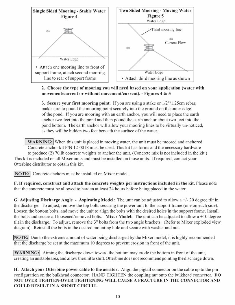
2. Choose the type of mooring you will need based on your application (water withmovement/current or without movement/current). - Figures 4 & 5
3. Secure your first mooring point. If you are using a stake or 1/2"/1.25cm rebar,make sure to pound the mooring point securely into the ground on the outer edgeof the pond. If you are mooring with an earth anchor, you will need to place the earthanchor two feet into the pond and then pound the earth anchor about two feet into thepond bottom. The earth anchor will allow your mooring lines to be virtually un-noticed,as they will be hidden two feet beneath the surface of the water.
WARNING: When this unit is placed in moving water, the unit must be moored and anchored.Concrete anchor kit P/N 12-0018 must be used. This kit has forms and the necessary hardwareto produce (2) 70 lb concrete weights to anchor the unit. (Concrete mix is not included in the kit.)
This kit is included on all Mixer units and must be installed on those units. If required, contact yourOtterbine distributor to obtain this kit.
NOTE: Concrete anchors must be installed on Mixer model.
F. If required, construct and attach the concrete weights per instructions included in the kit. Please notethat the concrete must be allowed to harden at least 24 hours before being placed in the water.
G. Adjusting Discharge Angle - Aspirating Model: The unit can be adjusted to allow a +/- 20 degree tilt inthe discharge. To adjust, remove the top bolts securing the power unit to the support frame (one on each side).Loosen the bottom bolts, and move the unit to align the bolts with the desired holes in the support frame. Installthe bolts and secure all loosened/removed bolts. Mixer Model: The unit can be adjusted to allow a +10 degreetilt in the discharge. To adjust, remove the 3" bolts from the two angle brackets. (Refer to Mixer exploded viewdiagram). Reinstall the bolts in the desired mounting hole and secure with washer and nut.
NOTE: Due to the extreme amount of water being discharged by the Mixer model, it is highly recommendedthat the discharge be set at the maximum 10 degrees to prevent erosion in front of the unit.
WARNING: Aiming the discharge down toward the bottom may erode the bottom in front of the unit,creating an unstable area, and allow the unit to shift. Otterbine does not recommend pointing the discharge down.
H. Attach your Otterbine power cable to the aerator. Align the pigtail connector on the cable up to the pinconfiguration on the bulkhead connector. HAND TIGHTEN the coupling nut onto the bulkhead connector. DONOT OVER TIGHTEN-OVER TIGHTENING WILL CAUSE A FRACTURE IN THE CONNECTOR ANDCOULD RESULT IN A SHORT CIRCUIT.
Single Sided Mooring - Stable WaterFigure 4
• Attach one mooring line to front ofsupport frame, attach second mooring
line to rear of support frame
Water Edge
Current Flow
Two Sided Mooring - Moving WaterFigure 5
Water Edge• Attach third mooring line as shown
Third mooring line
Water Edge

11
Figure 8
Figure 6
Figure 7
I. Fasten the strain relief to the support frame.Using two ty-raps secure the cable to the side of thesupport frame and place a small loop in the cable betweenthe last ty-rap and the connector. (Refer to Figure 6)
J. Have your electrician perform an on-shore dry-run test:
1. Check and compare the actual power supply at the site to the information on the aerator'snameplate in regard to: motor voltage, phase, and frequency. IF THIS INFORMATION DOESNOT MATCH, DO NOT OPERATE THE UNIT!
2. With the aerator on dry land, attach the power cable to the aerator and power supply.
3. Turn the handle mechanism on exterior of the power control center to "ON" position.
4. Energize the unit by turning the "Hand, Off/Auto" switch to the "hand" position. Run theunit 2 minutes to break in the seals. DO NOT RUN UNIT FOR MORE THAN 2 MINUTES- MOTOR DAMAGE CAN OCCUR. Check for COUNTER CLOCKWISE rotation at this time.
5. Turn the "Hand/Off/Auto" switch to "Off" and the disconnect switch to "Off".
6. IF Steps 1-5 are successful, you are ready to install the unit in the water. Proceed withfollowing instructions.
*ON MIXER MODELS, STEPS K THROUGH NARE OMITTED.*K. Attach the aspirator tubing to the barbed fittingon the venturi assembly. (Refer to figure 7).Secure the tubing to the support frame using twoty-raps. Cut the tubing to the desired length,allowing for fluctuations in the water depth.Connect the float/coupling assembly to the other end.
NOTE: If the float is not desired, the aspirator tubing canbe secured to a rod or stake (Otterbine recommends usinga 1.5" PVC pipe) along the edge of the water. The end ofthe tube must be fasten above the water surface. Themuffler can be removed from the float and inserted intothe top of the tube. Refer to figure 8.
12
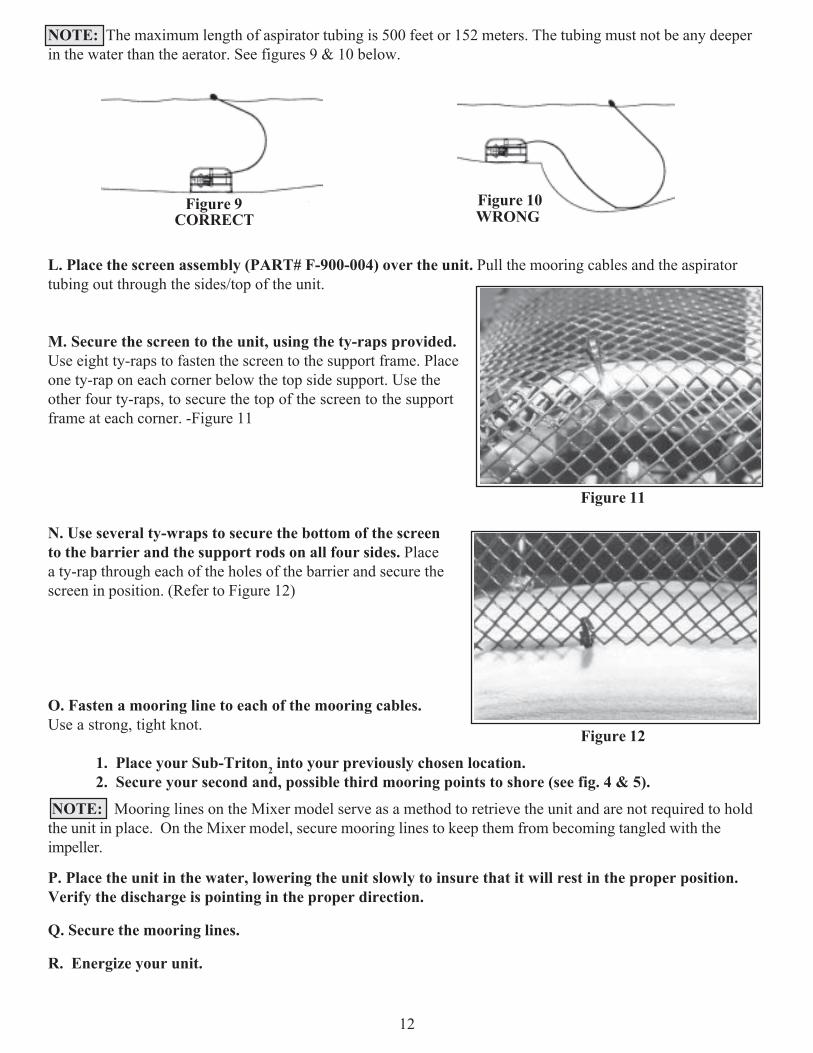
NOTE: The maximum length of aspirator tubing is 500 feet or 152 meters. The tubing must not be any deeperin the water than the aerator. See figures 9 & 10 below.
L. Place the screen assembly (PART# F-900-004) over the unit. Pull the mooring cables and the aspiratortubing out through the sides/top of the unit.
M. Secure the screen to the unit, using the ty-raps provided.Use eight ty-raps to fasten the screen to the support frame. Placeone ty-rap on each corner below the top side support. Use theother four ty-raps, to secure the top of the screen to the supportframe at each corner. -Figure 11
N. Use several ty-wraps to secure the bottom of the screento the barrier and the support rods on all four sides. Placea ty-rap through each of the holes of the barrier and secure thescreen in position. (Refer to Figure 12)
O. Fasten a mooring line to each of the mooring cables.Use a strong, tight knot.
1. Place your Sub-Triton2 into your previously chosen location.2. Secure your second and, possible third mooring points to shore (see fig. 4 & 5).
P. Place the unit in the water, lowering the unit slowly to insure that it will rest in the proper position.Verify the discharge is pointing in the proper direction.
Q. Secure the mooring lines.
R. Energize your unit.
Figure 9CORRECT
Figure 10WRONG
Figure 12
Figure 11
NOTE: Mooring lines on the Mixer model serve as a method to retrieve the unit and are not required to holdthe unit in place. On the Mixer model, secure mooring lines to keep them from becoming tangled with theimpeller.

13
A B C A B C A B C1 2 3 3 1 2 2 3 1
S. Have your electrician do the following while the unit is in the water under load.
1 PHASE UNITS: Record running voltage and running amperage, power control center serial#, and cablelength and size (gauge) on the sticker inside the power control panel. Proceed to step T.
3 PHASE UNITS: OTTERBINE aerators are designed to run in a COUNTER CLOCKWISE DIREC-TION. CURRENT UNBALANCE BETWEEN THE LEGS ON 3 PHASE UNITS SHOULD NOT EX-CEED 5%. Steps 1-6 below will help determine current unbalance.
1. Check the direction of rotation. Three phase motors can run in either direction depending on howthey are connected to the power supply. When the three cable leads are first connected to the powersupply, there is a 50% chance that the motor will run in the right direction.
2. Verify correct motor rotation (Counter Clockwise). Rotation can be changed by exchanging anytwo of the three motor leads. FAILURE TO DO THE ABOVE MAY CAUSE THE MOTOR TOFAIL PREMATURELY. MOTOR FAILURE DUE TO REVERSED POLARITY (ROTATION)WILL NOT BE COVERED UNDER WARRANTY.
3. Check current readings in amps on each leg using the three possible hook-ups. Roll themotor leads across the starter in the same direction to avoid motor reversal. EXAMPLE:
4. Calculate the percent of current unbalance:A. Add the three line amp values together.B. Divide the sum by three, yielding current average.C. Pick the amp value that is furthest from the average current (either high or low).D. Determine the difference between this amp value (line C) and the avg. (line B).E. Divide this difference (line D) by the average (line B).F. Multiply the result (line E) by 100 to determine percent of unbalance.
5. Current unbalance should not exceed 5% at the service factor load. If unbalance cannot becorrected by rolling leads, locate source of unbalance & correct it. IF leg furthest from average stays onthe same power lead, THEN the primary cause of unbalance is the power source. IF leg furthest fromaverage moves on each of the hookups with a particular motor lead, THEN the primary cause of unbalance is the "motor side" of starter. Consider: damaged cable, leaking splice, poor connection, or faultymotor as possible causes.
6. Record running voltage & running amperage, power control center serial #, and cable lengthand size (gauge) on the sticker inside the power control panel. Proceed to step T.
T. Lock your enclosure with a padlock to prevent any type of vandalism. Set the "hands off" switchlocated on the outside of your Power Control Center to the ON or AUTO position. The ON position on theswitch will let your aerator run continuously. The AUTO position on the switch will allow the automatic timerinside your aerator to operate the unit. See page 5 for timer operating instructions. Your aerator should berunning at this point and installation is complete.
CAUTION: The aerator should be allowed to run continuously for 12 hours after installation. Thiswill allow the aerator to properly "break in."
ATTENTION: l'aérateur doit être permi de fonctionner continuellement pendant 12 heures aprés l'installation.Cel permettra a l'aérateur d'être proprement rodé.

14
Technical Specifications - Aspirating ModelShippingWeight*
202 lbs.202 lbs.92 kilos202 lbs.92 kilos202 lbs.92 kilos205 lbs.205 lbs.205 lbs.93 kilos205 lbs.205 lbs.205 lbs.93 kilos
Min.Depth
2.5'2.5'
80 cm2.5'
80 cm2.5'
80 cm2.5'2.5'2.5'
80 cm2.5'2.5'2.5'
80 cm
Model
100
200
300
500
HP
111223333335555
Voltageand Phase
115 1Ph208-230 1Ph
220 1Ph208-230 1Ph
220 1Ph208-230 1Ph
220 1Ph208-230 3Ph
380 3Ph460 3Ph
380/415 3Ph208-230 3Ph
380 3Ph460 3Ph
380/415 3Ph
Motor RPM
1725@60Hz1725@60Hz1425@50Hz1725@60Hz1425@50Hz1725@60Hz1425@50Hz1725@60Hz1680 @60Hz1725@60Hz1425@50Hz1725@60Hz1680 @60Hz1725@60Hz1425@50Hz
RunningAmp Draw
12.66.57.311.512.012.514.58.74.74.14.313.57.57.06.2
**Pond VolumeInfluenced ft3
210,000210,000
794,850 liters420,000
1,589,700 liters630,000
2,384,550 liters630,000610,000630,000
2,384,550 liters1,050,0001,022,0001,050,000
3,974,250 liters*Shipping weight includes unit, 50' or 16.7 meters of cable and power control center. **Pond Volume influenced based fromempirical data and may vary due to voltage, elevation, and relative humidity.
2
1
3
4
5
6
7
8
9
10
100 125 150
1 HP
2 HP
3 HP
5 HP
250 50 754 5 61 2 3
2 HP
1 HP
3 HP
5 HP
5
10
15
20
25
30
35
0
SCFM (standard cubic feet perminute) OF AIR
DEP
TH O
F W
ATE
R IN
FEE
T
DEP
TH O
F W
ATE
R IN
MET
ERS
CLM (CUBIC LITERS PER MINUTE)OF AIR
ShippingWeight*
202 lbs.202 lbs.92 kilos202 lbs.92 kilos202 lbs.92 kilos205 lbs.205 lbs.205 lbs.93 kilos
**Pond VolumeInfluenced ft3
490,000490,000
1,854,650 liters980,000
3,709,300 liters1,470,000
5,563,950 liters1,470,0001,470,0001,430,000
5,563,950 liters
Model
100
200
300
HP
11122333333
Voltageand Phase
115 1Ph208-230 1Ph
220 1Ph208-230 1Ph
220 1Ph208-230 1Ph
220 1Ph208-230 3Ph
460 3Ph380 3Ph
380/415 3Ph
Motor RPM
1725@60Hz1725@60Hz1425@50Hz1725@60Hz1425@50Hz1725@60Hz1425@50Hz1725@60Hz1725@60Hz1680 @60Hz1425@50Hz
RunningAmp Draw
12.66.57.3
11.512.013.712.58.84.24.74.0
Min.Depth
3'3'
1m3'
1m3'
1m3'3'3'
1m
Technical Specifications - Mixer Model
*Shipping weight includes unit, 50' or 16.7 meters of cable and power control center. **Pond Volume influenced based fromempirical data and may vary due to voltage, elevation, and relative humidity.

15
Trouble Shooting Guide
Clogged air hose
Cut or broken hose
Motor running clockwise
Unit to deep
SYMPTOM POSSIBLE CAUSE CORRECTION
Remove debris
Replace hose
Have electrician switch twowires at starter (3 phase only)
Move unit to shallower water
1) No bubbles in waterdischarge(Aspirator model only)
Debris around impeller
Broken impeller
Remove debris
Replace impeller
2) No water discharge
Replace broken line
Tighten mooring line
Add anchor kit
Broken mooring line
Loose mooring line
Unit requires anchors
3) Aerator is wandering
4) Severe vibration Broken Impeller Replace Impeller
Blown fuse/breaker
Relay has tripped
Broken or disconnected wires
GFIC device has tripped
Short in power cable
Check fuses or breaker at P.C.C.
Check if overload relay tripped
Replace or attach loose or brokenwires
Reset and test GFCI device. Ifdevice trips again call electricianor authorized service center
Check condition of power cable
5) Motor will not start
WARNING: DISCONNECT THE UNIT FROM THE POWER SOURCEBEFORE SERVICING THE UNIT!
NOTE: Most problems will be found by pulling the aerator out of the water.
16
Maintenance
Your Sub-Triton2 aeration system requires periodic maintenance.
A. Once a year, disconnect the unit from the power source and physically inspect the aerator and under-water cable for any cuts, cracks, or breaks in the power cable connector. These may cause oil leaks and/orelectrical shorts. Inspect and clean the pumping chamber component.
B. After every three operating seasons, a simple oil change is necessary to keep your unit runningsmoothly. Please contact your local Otterbine distributor to order a maintenance kit, PART #C2-MKIT.
When a unit is properly cared for it will give you years of trouble free service. If any problems arise, pleasecontact your Otterbine distributor or the factory directly at 1-800-AER8TER.
WARNING: DISCONNECT THE UNIT FROM THE POWER SOURCEBEFORE SERVICING THE UNIT!! !
WARNING:
• Before entering, wading in or swimming in the water in which Otterbine Aerators or Fountains areinstalled, make sure they are PHYSICALLY disconnected from their electrical power sources.• Aerators located in or near garden ponds and similar locations must be equipped with Ground FaultCircuit Interrupter.• The permissible temperature range for this equipment is -12o to 40o C/10o to 104o F.• It is possible for the water to become slightly polluted in the rare case that an oil leakage
occurs.• If the power cord is damaged, it must be replaced by a special cord or assembly available
from Otterbine/ Barebo, Inc. or an authorized Otterbine/Barebo, Inc. sales and service center.
ADVERTISSEMENT:• Les aérateurs situes a courte distance ou proche de piscines, êtangs de jardin et semblable endroitsdoivent être équipés avec un interupteur avec control de defaut. S'il vous plait voyez votre distributeurd'Otterbine local pour priz et desponsibilitée.• La gamme de témperature permit pour cet équipement est de -12 a 40C/10 a 104F.• Si la corde électrique est abimée, elle doit être remplacée par une corde spécial ou assemblage disponible d'Otterbine®/Barebo, Inc. ou par un centre de service de vente authorisé par Otterbine®/Barebo, Inc.• L'eau pourrait devenir legérement pollue dans le trés rure cas ou l'huile fuirait.

17
DescriptionFloat/Coupling AssemblyMuffler
Screen AssemblyTy-rapConcrete weight kit
Qty.2122
4(2)4(2)
410(12)12(14)
21(0)0(1)
84
8(6)1(0)1(0)
50(0)
Part #10-000940-000310-0010106-30228-0018GP1208C2-111EP6301MP200140-001141-000441-000541-000240-000529-000446-000646-0007TUBING
Qty.1(0)1(0)
120
(0)1*
Part #10-001446-0005
F-900-004GP500812-0018
Item123456789
1011
121314151617
Item1819
202122
DescriptionSupport FrameSupport BraceMooring Cable Assembly5/16" Bolt5/16" Flat washer5/16"-18 Lock nut3/8" Bolt3/8" Lock washer3/8" Hex nutSupport RodBottom Barrier
Bushing2" Spacer3/8" Fender washerPipe nippleElbow fittingTubing
Note: quantity in "( )" is for Mixer vs. Aspirator.*Part number depends on model and horsepower.
19
Sub-Triton2 Exploded Parts Diagram
18 17
15
2
4 5
1
6
7 3
11 8 9 9 12
13
14 8 9 10
16
18
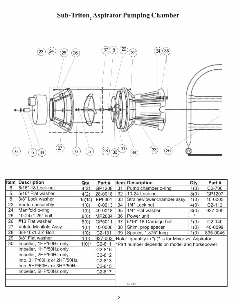
DescriptionPump chamber o-ring10-24 Lock nutStrainer/lower chamber assy.1/4" Lock nut1/4" Flat washerPower unit5/16"-18 Carriage boltShim, prop spacerSpacer, 1.375" long
Qty.4(2)4(2)
15(14)1(0)1(0)8(0)8(0)1(0)1(0)1(0)1(0)*
Part #GP120828-0018EP630110-001349-0018MP2004GP501110-0006C2-131927-003C2-811C2-816C2-812C2-813C2-815C2-817
Qty.1(0)8(0)1(0)4(0)8(0)
*1(0)1(0)1(0)
Part #C2-706GP120710-0005C2-112927-000
C2-14040-0099
895-0045
Item658
2324252627282930
Item313233343536373839
Description5/16"-18 Lock nut5/16" Flat washer3/8" Lock washerVenturi assemblyManifold o-ring10-24x1.25" bolt#10 Flat washerVolute Manifold Assy.3/8-16x1.25" Bolt3/8" Flat washerImpeller, 1HP/60Hz onlyImpeller, 1HP/50Hz onlyImpeller, 2HP/60Hz onlyImp.,3HP/60Hz or 2HP/50HzImp.,5HP/60Hz or 3HP/50HzImpeller, 5HP/50Hz only
2/28/00
Sub-Triton2 Aspirator Pumping Chamber
27 5 6 6 5
29
30
32
33
35
38
23 24 25 26
28
8
31
34
36
37
Note: quantity in "( )" is for Mixer vs. Aspirator.*Part number depends on model and horsepower.
39

19
Sub-Triton2 Mixer
Note: quantity in "( )" is for Mixer vs. Aspirator.
* Part number depends on model and horsepower. Items 11 and 65 secured using ty- rap P/N BP2874 (not illustrated)
Qty.0 (1)
10 (13)12 (14)
0 (1)4
8 (10)
0 (1)0 (1)0 (1)0 (1)0 (1)0 (4)4 (8)0 (1)
*(2)(2)(2)(4)
Description3/8" Bolt3/8" Lock Washer3/8" Hex NutBottom Barrier2" Spacer3/8" Fender WasherMixer Impeller w/ Set Screw1HP 60Hz2HP 60Hz & 1HP 50Hz3 HP 60 Hz & 2HP 50Hz3 HP 50 HzProtective CageCage Clamp1/4" Lock NutVortex PlateBrass RingMotor Base PlatePower Unit3/8-16 x 3" BoltAdjustment BracketSupport RodRod End Cap
Item789
11131460****
6263646566676869707172
Install Cage With 1/4" GapBetween Cage and Motor BasePlate
607
62
6463
65
67
6669 13 8
70
911
14
71
72
14
11/25/02
Part #C2-111EP6301MP200141-000540-000529-0004
50-0006-00150-0006-00250-0006-00350-0006-053
C2-340C2-345C2-11241-0006
ReferenceReference
*22-0004C2-35040-001146-0012
68
8

20
Limited 3 year (moving and related parts)+ 5 year (non-moving parts) Warranty
Otterbine® Product
WARRANTY: Barebo, Inc 3840 Main Road East, Emmaus Pennsylvania 18049,U.S.A. hereby war-rants, subject to the conditions hereinbelow set forth, that should the OTTERBINE product provedefective by reason of improper workmanship or materials at any time during the warranty period thePurchaser at retail will be guarantee that BAREBO will repair or replace the said OTTERBINE productas may be necessary to restore it to satisfactory operating condition, without any charge for materials orlabor necessarily incident to such repair or replacement, provided that:
a) The enclosed Warranty Registration Card should be mailed to BAREBO withinfifteen (15) days of the original receipt by the Purchaser at retail in order to avoid delays:
b) The OTTERBINE product must be delivered or shipped, prepaid, in its originalcontainer or a container offering an equal degree of protection, to BAREBO or afacility authorized by BAREBO to render the said repair or replacement servicesor, if purchased from an authorized OTTERBINE dealer, to such dealer;
c) The OTTERBINE product must not have been altered, repaired or serviced byanyone other than BAREBO, a service facility authorized by BAREBO to rendersuch service, or by an authorized BAREBO dealer, and the serial number of theOTTERBINE product must not have been removed or altered: and
d) The OTTERBINE product must not have been subjected to lightning strikes andother Acts of God, vandalism, freezing-in, accident, misuse or abuse, and must havebeen installed in conformance with applicable electrical codes (including properelectrical protection), and also installed, operated and maintained in accordance withguidelines in the Owner's Manual shipped with the Otterbine product.
No implied warranties of any kind are made by BAREBO in connection with this OTTERBINE product,and no other warranties, whether expressed or implied, including implied warranties of merchantabilityand fitness for a particular purpose, shall apply to this OTTERBINE product. Should this OTTERBINEproduct prove defective in workmanship or material, the retail Purchaser's sole remedy shall be repair orreplacement as is hereinabove expressly provided and, under no circumstances, shall BAREBO be liablefor any loss, damage or injury, direct or consequential, arising out of the use of, or inability to use, theOTTERBINE product, including but not limited to retail Purchaser's cost, loss of profits, goodwill,damages due to loss of product or interruption of service, or personal injuries to Purchaser or any person.

22
Water Works With Otterbine!
Otterbine Barebo, Inc.3840 Main Road EastEmmaus, PA. 18049
U.S.A.www.otterbine.com
1-800-AER8TER • (610) 965-6018FAX: (610) 965-6050
AERATOR MODEL
HORSEPOWER
VOLTAGE PHASE FREQUENCY
CORD LENGTH
UNIT SERIAL NUMBER
PCC SERIAL NUMBER
OPTIONS


