40 40 Low profile shower valves suitable for slim duct systems INSTALLER: After installation please pass this instruction booklet to user IMPORTANT BEFORE CONNECTION, FLUSH WATER THROUGH PIPEWORK TO REMOVE ALL DEBRIS ETC. WHICH COULD DAMAGE THE VALVE MECHANISM AS 4032.1 WMK 25821 SAI Global WaterMark TM Easybox Slim thermostatic built-in shower mixers INSTALLATION INSTRUCTIONS A6536AA built-in shower mi- xer with on/off flow control & square escutcheon plate A6655AA built-in shower mi- xer with 3 function diverter & square escutcheon plate
Transcript
40
40
Low profile shower valves suitable for slim duct systems
INSTALLER: After installation please pass this instruction booklet to user
IMPORTANTBEFORE CONNECTION, FLUSH WATER THROUGH PIPEWORK TO REMOVEALL DEBRIS ETC. WHICH COULD DAMAGE THE VALVE MECHANISM
AS 4032.1 WMK 25821 SAI Global
WaterMark
TM
Easybox Slim thermostatic built-in shower mixers
INSTALLATIONINSTRUCTIONS
A6536AA built-in shower mi-xer with on/off flow control & square escutcheon plate
A6655AA built-in shower mi-xer with 3 function diverter & square escutcheon plate
6.9 Examples of installations .................................................................................................21
7 Preparation for chrome trim (kit-2) ....................................................................... 277.1 Description of chrome trim (kit-2) ....................................................................................28
7.2 Installation of chrome trim (kit-2) .....................................................................................28
7.3 Products with integral diverter .............................................................................................31
8 Operation ............................................................................................................. 319 Maximum temperature stop ................................................................................. 3310 Calibration of thermostat ...................................................................................... 3311 Isolating valves & Maintenance ............................................................................ 33
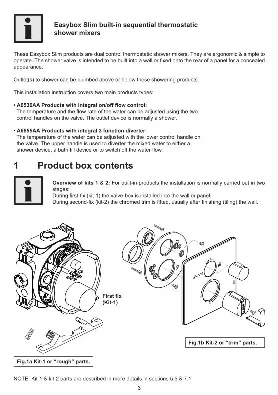
NOTE: Kit-1 & kit-2 parts are described in more details in sections 5.5 & 7.1
Overview of kits 1 & 2: For built-in products the installation is normally carried out in two stages:Duringfirst-fix(kit-1)thevalve-boxisinstalledintothewallorpanel.Duringsecond-fix(kit-2)thechromedtrimisfitted,usuallyafterfinishing(tiling)thewall.
These Easybox Slim products are dual control thermostatic shower mixers. They are ergonomic & simple to operate.Theshowervalveisintendedtobebuiltintoawallorfixedontotherearofapanelforaconcealedappearance.
Outlet(s) to shower can be plumbed above or below these showering products.
This installation instruction covers two main products types:
• A6536AA Products with integral on/off flow control: Thetemperatureandtheflowrateofthewatercanbeadjustedusingthetwo control handles on the valve. The outlet device is normally a shower.
• A6655AA Products with integral 3 function diverter: The temperature of the water can be adjusted with the lower control handle on the valve. The upper handle is used to diverter the mixed water to either a showerdevice,abathfilldeviceortoswitchoffthewaterflow.
IMPORTANT: Prior to installing mixer, ensure that any existing thermostatic mixing valves (TMVs) that may be fitted are removed
G 1/2
G 1/2
G 1/2G 1/2
30-65
5-40
18
144148 82
148
82
Ø128
MIN
MA
X
Valve-box dimensions with OPTIONAL legs fitted
4
63 - 73
40 - 50
58 - 68
47 - 57
144
G 1/2
G 1/2
185G 1/2
185
2837 G 1/2
151
200
22075
Square escutcheon shower valve. Shown with valve-box, trim & mounting bracket
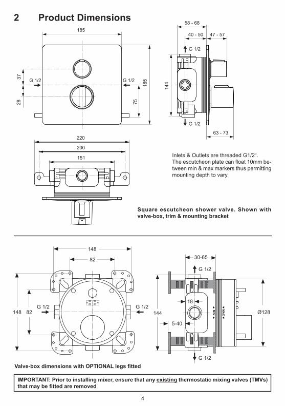
Inlets & Outlets are threaded G1/2“.Theescutcheonplatecanfloat10mmbe-tween min & max markers thus permitting mounting depth to vary.
2 Product Dimensions
5
Differential betwenn Cold inlet temperature & MIXED temperature must be 24°C min.
Operating pressure range: High Pressure Low Pressure
Maximum static pressure 1000 KPa 1000 KPa
Flow pressure hot and cold 50 to 500 KPa 10 to 100 KPa
Hot supply temperature 55 to 65 °C 55 to 65 °C
Cold supply temperature up to 25 °C max up to 25 °C max
Temperature differential characteristic (TDC) 10 °C 10°C
Max outlet pressure in accordance with AS/NZS 3500 = 500 KPa
3 Supply Conditions
4 National Plumbing & Drainage Code
Supply temperatures:Temperatures shown above are for the HOT inlet water supply. Avoid supplying scalding water to the HOT inlet.
In order to maintain water quality, the hot supply should be stored & distributed at a temperature greater than 55°C.
Supply pressures:Products should be plumbed to balanced pressure water supplies for best mixing performance.
The recommended working pressure for these products is shown above.Exceeding these pressures will adversely affect the operation of the shower.This adverse effect can be overcome by using PRV to reduce the pressure accordingly.
NOTE: Maximum recommended static pressure in AS 3500.1.2 is 500 Kpa.To avoid exceeding this pressure, install a suitable pressure reducing valve - PRV (or pressure limiting valve - PLV) on both hot & cold incoming water supply systems. A suitable location for a PRV on the hot supply may be on the cold inlet to the heating appliance.Similarly, if the water supply temperature ranges do not conform as above, then suitable temperature controlling devices should be installed to achieve this.
The products covered by this installation and maintenance instruction must be installed in accord-ance with the provisions of AS/NZS 3500 & any relevant local regulations. Installations not complying with AS/NZS 3500 may void the product performance & warranty.ArmitageShanksstronglyrecommendsthatthisproductisfittedbyaprofessionalinstaller.
4.1 Water supply controlling devices (external)
Fig.3
Isolation valves MUST be fitted to permit future maintenance of these products. Strainers are included with this product inside the check valve housing, see 6.8.
Isolationvalvesshouldbefittedascloseasispracticabletothewatersupplyinletsofthethermostaticshower valve, in an easily accessible location. See 11 for more details.
6
4.2 Field tests & reportsCommissioning,fieldperformancetests,repairs&ongoingmaintenanceshouldberecordedinaccord-ance to AS 4032.3 for each thermostatic mixer installed (or in some cases to the relevant monitoring authority).Statutory requirements in AS 4032.3 should be observed with regards to maintenance protocols, perfor-mance testing, data recording & calibrated measuring equipment.
The documentation used by the tester (or installer) for recording data can be either manual (paper) or electronic system. The reporting documents can be:•Anestablishedformatalreadyacceptedonsitebythelocalfacilitymanager*.•ThetypicalformatshowninappendixEofAS4032.3.•Aformatspecifiedbytherelevantmonitoringauthority.
A copy of the reports should be:•Retainerbythetester.•Forwardedtothelocalfacilitymanager&beavailableonsiteforinspection.•Ifnecessary,forwardedtotherelevantmonitoringauthority.
Priortofieldtestingormaintenanceworkonsite,thelocalfacilitymanagershouldbenotifiedthatthewater service may be affected & delivery temperatures may vary during the testing period.
It is important to note that if the mixer is dismantled, repaired or adjusted, the commissioning procedure should be repeated.
(* Where facility manager can be site owner, site occupier or responsible person.)
5 Pre-installation notes5.1 Kit-1 mounting depth control
IMPORTANT: For trouble-free installation of these built-in products the depth controls shown must be observed. Using a spirit level ensure valve-box is level in all 3 directions.Thevalve-boxismarkedwithMIN&MAXdepthsettings,thefinishedwall(aftertiling)shouldliebetween these markers as shown
MAX
MIN MAX
MIN
Finished wall or panel
Lines on valve.boxserve as trimming guidefor installing kit-2
When calculating depth, consider thickness of plaster, tile adhesive, & tiles (if applicable).
7
5.1Kit-1 mounting depth control cont’Effectively,theescutcheonplatecanfloat10mm,betweentheMIN&MAX(markersonthevalve-box)thuspermitting the mounting depth to vary by 10mm.
44
58 Min 68 MaxValve-boxshoulder
Min shroudexposure
Max shroudexposure
Cosmetically, when the escutcheon plate is furthest back (valve-box trimmed at MIN), this exposes more of the shroud diameters under the handle.
Conversely, when the escutcheon plate is furthest forward (valve-box trimmed at MAX), the shroud diameters under the handle are hardly noticeable.
Valve-box shoulderThe valve-box shoulders are created by the bosses surrounding the ports of the valve. For example, if the valve-box is being panel mounted, the large diameter of the valve-box will pass through a hole in the panel & eventually stop against these shoulders.
See 6.7 for an example of how these shoulders can be used as a stop face.
8
MIN
MA
X
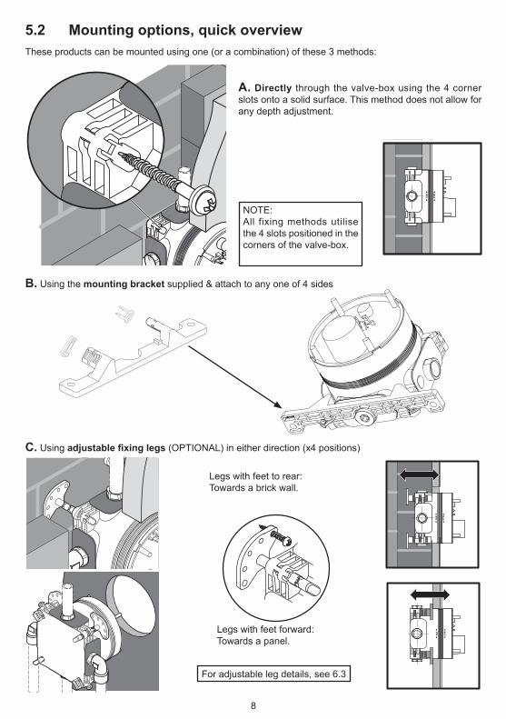
IThese products can be mounted using one (or a combination) of these 3 methods:
MIN
MA
X
IA. Directly through the valve-box using the 4 corner slots onto a solid surface. This method does not allow for any depth adjustment.
NOTE:All fixing methods utilise the 4 slots positioned in the corners of the valve-box.
B. Using the mounting bracket supplied & attach to any one of 4 sides
C. Using adjustable fixing legs (OPTIONAL) in either direction (x4 positions)
MIN
MA
X
MIN
MA
X
Legs with feet to rear:Towards a brick wall.
Legs with feet forward:Towards a panel.
For adjustable leg details, see 6.3
5.2 Mounting options, quick overview
COLD
BOTTOM
TOP
HOT
TOP
9
5.3 Wall types, quick overviewThese built-in products are designed for easy installation into most common wall types. Theselowprofilevalvesareespeciallysuitableforslimductsystemswheretheminimumwallcavitydepthcan be as little as 44mm. • Solid brick walls: See 6.4 Installer can chase-out brick work to create a cavity and then choose a mounting option. Alternatively, the installer may surface mount the valve onto a wall & then build a framework for a false partition or panelling system to conceal the valve-box & pipes. • Pre-fabricated “pod” style bathrooms: See 6.5 The valve-box can easily be mounted from the rear of the pod wall during pod construction.Thissimplifiesplumbing.Thechromedtrimcanthenbefittedfromthe front (from inside the pod) after tiling. • Panel mounting: See 6.6Valve-boxcanbepanelmountedprovidingaccessisavailablefromrearforfixingthe valve-box to the panel & for attaching pipe-work. • Partition walls: See 6.7 The valve-box can easily be mounted into a timber stud or metal frame construction wall. A versatile mounting bracket is supplied with this product which permits the valve-box to be anchored to a timber noggin or stud using any one of the four valve-box sides.
5.4 Valve-box orientationIt is important to maintain the valve-box orientation correct through out the installation. Otherwise the handle positions & escutcheon marking will be incorrect.
Valve-box shown correctly orien-tated with plaster guard removed.
Ensure valve-box is level in all directions.VALVE-BOX SHOULD NOT BE MOUNTED ONTO A HORIZONTAL SURFACE.
Valve-box shown correctly orientated with plaster guard in place.
10
5.5 Kit-1 description
Thebuilt-invalve-boxissuppliedwithaplasterguard(protectivecover)fittedasshown.Theplasterguardprevents debris entering into the valve-box during installation. Additionally, the plaster guard also serves as an aid to levelling the valve-box whilst mounting onto a wall or panel.
OBSERVE ORIENTATION OF VALVE-BOX, SEE 5.4
2x inletsat sides
2x outlets at top&bottom
Sealed valve-box
4 mounting slots in corners of valve-box Trimming
guide lines
Valve assemblyinside
Plaster guard
Plaster guardlocating lugs
This clip can be used to hold a miniature spirit level (not supplied)
4 bosses can be used as a platform for a spirit level during installation
IMPORTANT:Thevalve-boxisfittedwithsealstopreventanywaterfromleakingintothewall cavity. Therefore the inside of the valve-box should not be drilled otherwise water tightness will be lost. See 5.6.ALWAYS UTILISE THE 4 SLOTS PROVIDED IN THE CORNERS OF THE VALVE-BOX FOR MOUNTING THESE PRODUCTS.
Latching clips: (pair supplied) are used to attach and secure the mounting bracket (& adjustable legs) to the valve-box by using a pair of corner slots. A mounting bracket is also supplied, see 5.2B.
Blanking plug: (threaded G1/2”) to permit one mixed water outlet (either top or bottom) to be blanked-off (if it is not required). Use a 10mm Allen Key to drive plug. Plug is not sup-plied with diverter version of products. Use an appropriate sealing compound.
Fleece mat: (tiling aid) is supplied to help protect the wall cavity from water splashes which might penetrate from any gaps in the tiles around the valve-box. The mat should be placed over the valve-box and bonded to the wall using tile adhesive immediately prior to tiling (see 5.6). Thefleecematissoft&flexible(waterresistant)&willstretcharoundthevalve-boxdiam-eter. For panel installations, the mat can be discarded & a suitable sealant should be used around the panel hole.
11
The built-in valve-box is designed with an extensive sealing system to prevent water penetration in two ways: Firstly, any trickles of water resulting from a minor leak inside the valve-box are prevented from entering into the wall cavity. Secondly, any water spray from the shower area is prevented from entering the valve-box.
Fleece mat: is bonded between the wall & the tiles. Mat prevents spay water from the shower entering into the wall cavity.See positioning illustration below:
Lateral seals: All 4 pipe connection ports are reliably sealed all round.These seals prevent water trickles from minor leaks from the valve-box entering into the wall cavity.
Valve-box lid: has precision seals injec-tion moulded to it, thus preventing seals from being lost.Lid prevents spay water from the shower entering into the valve-box.
O-ring seals: Both handle shrouds are sealed with o-rings, preventing spay water from the shower entering into the valve-box.
Leak warning system: In the event of a leak occurring inside the valve-box, the accumulated water will begin to drip from the gap between the temperature handle & the shroud. If a drip occurs, this indicates there isaproblem&thechrometrimkitshouldberemoved&theleakfixed.Thisleakpathisdesignedtofreelypermit drainage of water from inside the valve-box into the wet area of the bathroom (but prevent water from escaping into the wall cavity).
IMPORTANT: inside of valve-box should not be drilled otherwise water tightness will be lost.
5.6 Valve-box sealing system
6 Installation guide – kit.1The thermostatic mixing valve must be installed in such a position that maintenance of the TMV and its valves and the commissioning and testing of the TMV can be undertaken.
IMPORTANTBEFORE CONNECTION, FLUSH WATER THROUGH PIPEWORK TO RE-MOVE ALL DEBRIS ETC. WHICH COULD DAMAGE THE VALVE MECHANISM
NOTES:These products are intended for installation into vertical walls. Installing into a horizontal surface is not recommended.Isolating valves should be installed into the supply pipe-work to permit future servicing & maintenance.
6.1 Connecting pipe-work - preliminary
G1/2
G1/2
COLD water supply pipe
HOT water supply pipe
Example: Bottom outlet to tub �ll
Some pipe-work can be connected to the valve-box prior to mounting into the wall.
Example: Top outlet to shower•ApplyPTFEtapeorsimilar
to inlet elbow threads.
•Holdconnector invalve-box stationary,using 25mm open ended spanner.Tighten elbow into connector
Alternatively, instead of PTFE tape, use an approved thread sealant; e.g.: Loctite 577 or Permabond A1044. DO NOT SOLDER NEAR VALVE-BOX.
12
Water supply pipesWater supply pipes can be from any direction. Where supplies are provided from above, this normallypermits better drain down of pipe-work. Pipe-work should be secured to the wall or panel using suitable fixingclips.
DO NOT apply heat near this product. Heat generated by soldering could damage plastic parts and seals
Suitable pipe connectorsAll 4 connections to this product are threaded G1/2” female. Suitable pipe connectors can be obtained from all good plumbers merchants (not supplied).
Remember: a blanking plug is supplied (see 5.5) & can be used on one outlet.Use: elbows on the inlets & straight couplers on the outlets.
6.2 Mounting methodsWith ref to 5.2, decide on the most appropriate mounting method for the wall type.If using options B or C,attachthemountingbracket(orfixinglegs)tothevalve-box.
Using mounting bracket (method B).To attach the mounting bracket to the valve-box:First decide on which one of the four sides of the valve-box will be used for mounting.Insert the two lobes of the bracket into an appropriate pair of slots in the valve-box.If necessary, the bracket can be inserted into the valve-box from the rear.
Once the bracket is fully inserted into the valve-box, push the two latching clips home into their slots until they click in place.
Valve-box with mounting bracket&latchingclipfitted.
For mounting bracket dimensional information see Section 2
13
Method B: cont.Attaching the mounting bracket to either top or bottom of the valve-box permits the product to be secured to a timber noggin (horizontal) in a partition wall. Alternatively, attach the bracket to either side of the valve-box toutiliseanearbytimberstud(vertical)forfixing.
Toattachthefixinglegstothevalve-box:For a solid wall insert each leg into a slot from the rear. Select a suitable depth by aligning a groove on the leg to the clip-slot then push the latching clip home until it clicks.
Similarly for panel mounting insert each leg into a slot from the front. Select suitable depth & secure all 4 legs with latching clips.
Note; If further depth adjustment is required, the latching clips can be easily be removed by pulling on the projecting lobe of the clip. Slide the leg along the slot until a more suitable leg-groove is visible, and then refitthelatchingclipstosecure.
ADJUSTMENTNOTE:Thefixinglegshave4groovespermitting4depthsettings.Ensure all 4 legs are secured at the same depth.
For leg dimensional information & orientation, see section 2.
NOTE: Adjustable legs are not supplied with these products. Contact Customer Service to purchase a leg kit by quoting spares code: A963131NU. Each kit contains 4 adjustable legs and 4 latching clips.
For wall mounting, fitlegsfromrear.
Fit latching clips to secure legs
Valve-box with legsfittedtorear
5 screw holes
For panel mounting, fitlegsfromfront
6.3 Using OPTIONAL adjustable fixing legs (method C)
14
Before commencing, decide on which installation method to adopt from the two detailed below. Mark the wall at the desired location for the valve-box. Decide on preferred mounting option (see 5.2). Note: before mounting,itmaybeeasiertofitpipeconnectorstothevalve-box(see6.1).
CAVITY METHOD requires the installer to chase-out the brick-work to the required depth. Then mount the valve-box & pipe-work into this cavity. The cavity can then be closed-off for example with plaster board. Cut large hole in the covering plaster board to suit the valve-box diameter (see below).
FALSE-PARTITION METHOD requires the installer to mount the valve-box directly onto the wall, then build a false partition or use a panelling system in front of the wall to conceal the valve-box & pipe-work. The false wall can be just local to the valve area.Cut large hole in the covering panel to suit the valve-box diameter (see below).
Ø133
Checklevel&valve-boxorientation(see5.4).Confirmvalve-boxisprojectingcorrectlyfromthewall;suchthatthefinishedwallwillfallbetweenthedepthmarkers(see5.1).Forbothmethods,drillatlease4fixingholesinthewall&fitsuitablewallplugsforscrewtypebeingused.Ensure valve-box is securely attached to the wall.
Use suitable sup-porting washers under the screw heads
The large hole to be cut in the panel or plaster board should be Ø133mm (5.1/4”), which permits some clearance around the valve-box diameter (Ø129mm)
ENSURE THIS HOLE IS ADEQUTELY SEALED. USE THE FLEECE MAT SUPPLIED WHEN TILING OR USE A SUIT-ABLE SEALANT FOR PANEL INSTALLATIONS.
WARNING: Cavity should only be closed off when all pipe-work has been checked for leaks. Remember isolating valves must be installed in an easily accessible location
6.4 Mounting valve-box into a solid wall
15
6.4 Mounting valve-box onto a solid wall, cont’
MIN
MA
XM
IN
MA
X
Cavity, either chased-out brickwork or timber studs
Solid wall Either tiled plaster board or panelling system
Use suitable support-ing washers under the screw heads
Mounting option A (direct) through the valve-box using the 4 corner slots
Observe depth
Note: using mounting option A, (direct) provides the shallowest cavity depth, but does not permit any depth adjustment.
Mounting option C illustrated here using OPTIONALadjustablefixinglegs.
Adjustable legs Observe depth
16
For adjustable leg details, see 6.3
These products can be installed into a modern pre-fabricated pod style bathroom. The valve-box can be mounted into the pod wall from the rear during the pod construction. Note: before mounting,itmaybeeasiertofitpipeconnectorstothevalve-box(see6.1).
Typically, a pod wall is constructed with vertical steel members (40mm “U” section)setat300mmcentres.Frameworkisthenlinedinternallywith15mmfireresistantplasterboard.Decideonpreferred mounting option (see 5.2).
BRACING BRACKET METHOD where the installer can design & fabricate a metal bracket to brace over two vertical members of the pod wall. The bracing bracket is normally bolted to the vertical members. The valve-box can then be bolted onto this bracket either directly using the 4 corner slots (M8 bolts max) or by using the OPTIONAL legs (M5 bolts max).
A large hole should be cut in the plasterboard (see 6.4) to permit diameter of valve-box to pass though. Checklevel&valve-boxorientation(see5.4).Confirmvalve-boxisprojectingcorrectlyinsidepod;suchthatthefinishedwallwillfallbetweenthedepthmarkers(see5.1).
MIN
MA
X
Mounting option A (direct)canbeusedtofixthevalveboxtothebracketus-ingsuitablefixingbolts(M8max).Boltscanbefittedfromthefrontorfromthereartosecurethevalve-boxtothe bracing bracket.
Use suitable supporting washers under the bolt heads if necessary. To ensure valve box is securely fastened to bracket, use at least 4 bolts.
6.5 Mounting valve-box into a pre-fabricated pod wall
17
For adjustable leg details, see 6.3
6.6 Mounting valve-box into a panel
Recommended panel thickness should be in the range 14.5 to 26mm. Cut large hole in the panel (see 6.4) at the desired location for the valve-box. Decide on preferred mounting option (see 5.2). Two mounting methods are discussed below.Note:beforemounting,itmaybeeasiertofitpipeconnectorstovalve-box(see6.1).
DIRECT MOUNTING OPTION (A) can be used with long wood screws and suitable washers. Guide the valve-box into the large hole, until it stops against the rear of the panel. Check level & valve-boxorientation(see5.4).Confirmvalve-boxisprojectingfrom the front of the panel between the min & max depth markers (see 5.1). Pack-out if necessary.
Fit a screw into each corner slot of the valve-box fromthe rear to secure to panel. Care should be taken to prevent screws drifting towards the large hole.
ADJUSTABLELEGSOPTION(C)fittheOPTIONALlegstothevalve-box,fromthefront;tothedesireddepth (see 5.2C & 6.3). Guide the valve-box into the large hole, until the legs stop against the rear of the panel.Checklevel&valve-boxorientation(see5.4).Confirmvalve-boxisprojectingfromthefrontofthepanel between the min & max depth markers (see 5.1). Adjust leg positions if necessary.Mountthevalve-boxtothepanelusingwoodscrewsthoughthelegfixingholes
MIN
MA
X
IMPORTANT: Ensure the panel is capable of supporting the valve-box securely with the screws being used. Check that the screw length will not penetrate through the front of the panel & spoil the visible surface.
These products can be installed into a modern timber stud construction partition wall.The mounting bracket supplied (option B) can be attached to any side of the valve-box (see 5.2B & 6.2). This enables the valve-box to be secured to either a timber stud (vertical on either side) or to a timber noggin (horizontal, below or above the valve-box).Mounting bracket can be secured from in-front of the wall or from behind.Alternatively, the valve-box can also be mounted directly using the corner slots. Forretrofitfitapplications,anareaofplasterboardapproximately400x400shouldbecutawayandthenreplaced after installation. This is necessary to facilitate pipe connections. The framework may need to be adjusted to provide a means of fastening and supporting the product. TIMBER STUD WALL framework is normally constructed using 75x50 (3”x2”) rough sawn timbers, for larger walls 100x50 (4”x2”) can be used. Stud centres spacing of 400 is used here in discussion. Note that 450 and 600 centres are also commonly used - this usually dependents on the plaster board size being used. Plaster board thickness of 12.5 (1/2”) is generally recommended.
Rear view showing valve-box being mounted to a noggin below.Framework illustrated here uses 75x50 timbers on 400 centres.(Wall cavity = 75mm). Remember to make an allowance in framework for connecting pipes
Fit a horizontal noggin into the framework at the desired mounting location for the valve-box. The bottom surface of the bracket is 75mm from the centre of the valve-box. Therefore, the top edge of the noggin should be positioned 75mm below the desired valve-box centre. Ensure noggin is level & secured.
Installation of valve-box will be easier if the front plaster board is fastened to the timber framework, but don’t fasten the rear plasterboard until the installation is completed. Cut a large hole in the front plasterboard (see 6.4)atthedesiredlocationforthevalve-box.Note:Beforemounting,itmaybeeasiertofitpipeconnectorsto the valve-box (see 6.1).
Guide the valve-box into the large hole until it stops against the back of the plasterboard. The mounting bracketshouldbesittingonthenoggin.Checklevel&valve-boxorientation(see5.4).Confirmvalve-boxisprojectingfromthefrontoftheplasterboardcorrectly;suchthatthefinishedwallwillfallbetweenthedepthmarkers (see 5.1). The valve-box can be slid along the noggin until this depth is achieved.Fit two suitable wood screws through the bracket into the noggin to secure.
Using this method the min’ wall cavity depth can be as little as 44mm.
Studs
Noggin2holesforfixingsrews
19
6.7 Mounting valve-box into a timber stud wall, cont
Illustratedabove,valve-boxbeingmountedontoapairofslimnoggins(30mm*)attachedtothebackofapair of studs. Framework shown here uses 75x50 timbers on 400 centres. (Wall cavity = 75mm).
DIRECT MOUNTING OPTION (A) can be used with long wood screws and suitable washers. Position the valve-box onto the noggins. Check level & valve-box orientation (see 5.4).Confirmvalve-boxwillprojectfromthefrontplasterboard between the min & max depth markers (see 5.1). Pack-out if necessary.Fit a screw into each corner slot of the valve-box from the front to secure to the framework.
DEEP CAVITY WALLSIn some cases the partition wall may use timbers which are 100x50 or greater.*Nogginthicknessshouldbeadjustedaccordingly.
Greater wall cavity will also permit mounting by using adjustable legs kit. In principle, the method is same as shown in 6.4 (for solid wall). In this case the legs could be secured to a pair of noggins as shown above.
(Typical dimensions are given here, for guidance only).Mounting bracket
Stud Stud
44 min cavity
Tiles 8-10Observe depth
Adhesive 2-3
Plasterboard 12,5
Plan view showing valve-box installed into partition wall, using mounting bracket.
Direct mountingAlternatively, the valve-box can be mounted directly using the corner slots.
20
6.8 Completing pipe-work
The valve-box should now be securely mounted in the wall or panelatthedesiredlocation.Ifnotalreadydoneso,fitconnectorsto the valve-box, see 6.1. Remember one outlet can be closed off using the blanking plug (see 5.5).Some preliminary pipe-work may already be attached to the valve-box.
Complete all plumbing to valve-box & to outlet device(s). Observe appropriate connections points, see 5.4. For examples of pipe-work solutions see 6.9.Remembertofitisolatingvalvesinthesupplypipesataneasilyaccessible location.
Before closing wall cavity, switch on the water supplies & check all pipe-work & connections for leaks.
Whereappropriate,thewallcanbefinishedwithtiles.
6.9 Examples of installationsThis section illustrates just a few examples of how to run pipe-work to other bathroom accessories. Easybox Slimproductscanbeusedwithmanydifferentcombinationsofshowerkits&tubfillingproducts.Contactourrepresentatives or customer care for more details.The illustrations shown should only be used as guidelines for possible solutions for a bathroom layout. Con-sult a professional plumber for advice on how to customise the best solution for your bathroom.
NOTE: The check valve housings also permit the supplyingpipestobeflushedthroughthevalve-box: •Isolatethewatersupplies.•Pulloffplasterguardfromthevalve-box(iffitted).•Removethetwocheck-valve housings (Use 15mm A/F socket). •Placeavesselunderthevalve-box.•Gentlyopentheisolatingvalvesallowing water to be discharged from the open areas.
Avoid dripping water onto panels, plaster board &floor.Uponcompletionofflushing,reversetheabove procedure.
Integral check valves
Theseproductsarefittedwithintegralcheckvalvesonbothinletstocomplywithwaterregulations.Thecheckvalvehousingsincludestrainers(filters).Fromtimetotimeitmaybecomenecessarytocleandebrisfrom the check-valves & strainers. See section 15.These mechanisms should be cleaned carefully.
21
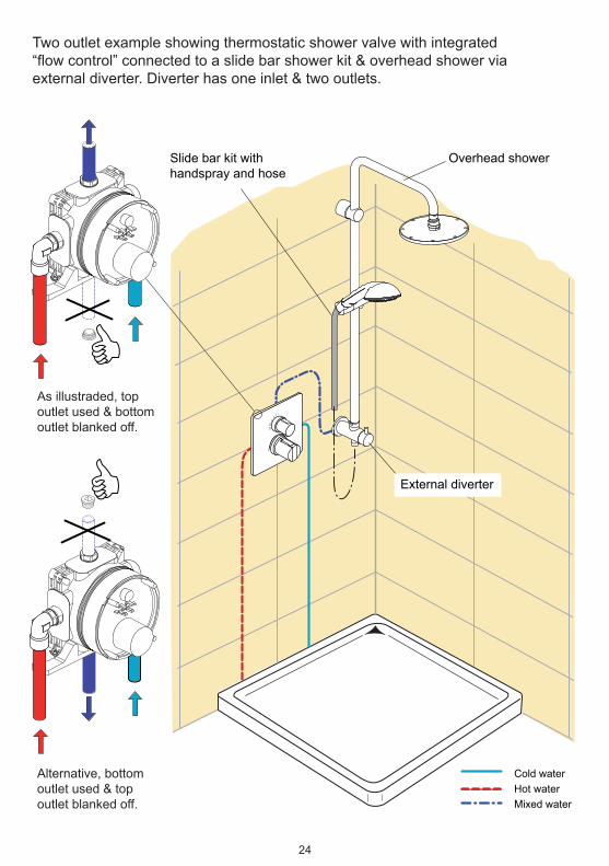
Slide bar kit withhandspray and hose
Cold waterHot waterMixed water
As illustraded, topoutlet used & bottomoutlet blanked off.
Alternative, bottomoutlet used & topoutlet blanked off.
Basic installation example showing thermostatic shower valve with integrated“flow control” connected to a single outlet slide bar shower kit.
40
Wall outlet elbow to hose
22
6.9 Examples of installations cont.…
Slide bar kit withhandspray and hose
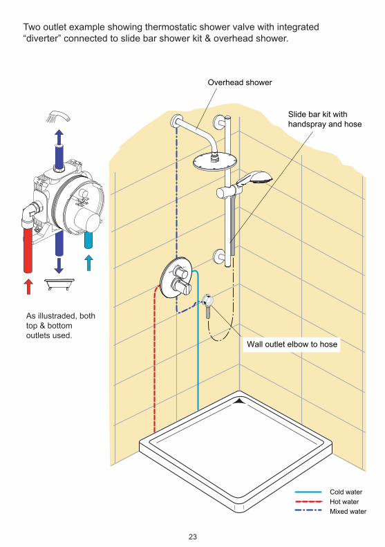
Overhead shower
Cold waterHot waterMixed water
As illustraded, bothtop & bottomoutlets used.
Two outlet example showing thermostatic shower valve with integrated“diverter” connected to slide bar shower kit & overhead shower.
Wall outlet elbow to hose
40
23
Overhead showerSlide bar kit withhandspray and hose
Cold waterHot waterMixed water
As illustraded, topoutlet used & bottomoutlet blanked off.
Alternative, bottomoutlet used & topoutlet blanked off.
Two outlet example showing thermostatic shower valve with integrated“flow control” connected to a slide bar shower kit & overhead shower viaexternal diverter. Diverter has one inlet & two outlets.
External diverter
40
24
Slide bar kit withhandspray and hose
Overhead shower
External diverter
Cold waterHot waterMixed water
As illustraded, bothtop & bottomoutlets used.
Three outlet example showing thermostatic shower valve with integrated“diverter” connected to a slide bar shower kit, overhead shower & body jetsvia an external diverter. Diverter has one inlet & two outlets.
Wall outlet elbow to hose
Body jets
40
25
Slide bar kit withhandspray and hose
Overhead shower
Cold waterHot waterMixed water
As illustraded, bothtop & bottomoutlets used.
Three outlet example showing thermostatic shower valve with integrated“diverter” connected to a slide bar shower kit, overhead shower & tub fill.External diverter has one inlet & two outlets.
RECOMMENDATION: Valve should be mounted at least 300mm above the bath rim.
40
300
COLD
BOTTOM
TOP
HOT
External diverter
Multiplex Trioor Idealfill
26
7 Preparation for chrome trim (kit-2)Oncethevalve-boxinstallationhasbeencompleted,&thewallisinafinishedstate(eithertiledorpanelfinish)theplasterguardcanberemoved&valve-boxmustbetrimmedasdetailedbelow.
NOTES:•Itisimportanttousethefleecematsuppliedtosealthewallaroundthevalve-box if wall is being tiling (see 5.5 & 5.6).•Walltilesshouldbecarefullytrimmedtomatchtheprojectingvalve-boxdiameter.•Removaloftrimkitwillpermitaccesstothevalvecartridgesforfuturemaintenance. To do this, just reverse the following installation sequence.
Pull of plasterguard
Illustratedabove,valve-boxprojectingfromthefinishedwallatthecorrectdepth.The plaster guard can now be removed to expose the valve assembly inside.Use a sharp craft knife to carefully trim the valve-box diameter. Select a suitable line marked on the diameter asatrimmingguide.Thediametershouldbetrimmedlevelwiththefinishedwall.Takecarenottodamagecomponents inside the valve-box
Illustrated on the left, the valve-box has been correctly trimmed. In this example, the product is the version with the integral“flowcontrol”.Thetrimkitcannowbefitted.
Trim kit screw identification
2x Up-stand bolts
1x Temperature handle screw
1x Flow control handle screw
2xLidfixingscrews
27
40
7.1 Description of chrome trim (kit-2)
7.2 Installation of chrome trim (kit-2)Ensure preparation work has been completed (see 7.0). The two up-stand bolts can be screwed into the valve body using a slotted screw driver at the positions shown. Do not screw these bolts right down, as they mayrequireadjustmenttoacceptthescrewsinthenextstep(forfixingthelid).
Up-stand bolts
Valve-box lid with integral seals
Lid fixing screws
Escutcheon plate:on/off flow control version
Flow control shroud (small)
Temperature shroud (large)
Temperature handle
Temperature handle cover
Flow control handle screw
Flow control handle
28
Temperature handle screw
Locationforfitting1st up-stand bolt
Shroud locat ing diameters (o-rings)
Location for fitting 2nd up-stand bolt
40
7.2 Installation of chrome trim (kit-2) cont’As a guide, the top of the bolt can be kept level with the wall.Note these special up-stand bolts are threaded internally & externally.
Fit both shrouds onto the appropriate housings. Apply a little soapy water to the o-rings that house the shrouds & then slide over. Note the shrouds will need to be adjusted at the end of the installation to close the gaps under the handles (by sliding along axis).
Next orientate the valve-box lid as shown.Align the lid bores to the shrouds & slide over. Gently push the lid onto the shrouds & the integral seals should make contact. Continue pushing the lid& the large corrugated lid seal should now engage into the valve-box bore. Push the lid further until the rear lid seal is firmlyagainstthewall.Pressthelidallaroundtheedgetoensure that it is level with the wall.Insertthelidfixingscrewsintothecountersunkholesinthelidasshown.Fixthescrewsusingaposiscrewdriver.DONOTOVERTIGHTEN.Thefixingscrewsshouldengageintothe up-stand bolts, if not, remove the lid & adjust the height of the up-stand bolts.
Location holes for escutcheon plate lugs
Valve-box lidfitted
Escutcheonplate
Rear view of escutcheon plate showing locating lugs
Shroudsfitted
Up-stand boltsfitted
Valve-box lid
Lidfixingscrews
Integral seals
29
7.2 Installation of chrome trim (kit-2) cont’Withthevalve-boxlidsecured,theescutcheonplatecanbefitted.Orientatetheescutcheonasshown.Guide the escutcheon over the two shrouds. The two locating lugs on the rear of the escutcheon should entertheholesinthevalve-boxlid.Pushtheescutcheonfirmlyuntilitmakescontactwiththewall.Pressthe escutcheon all around the edge to ensure that it is level with the wall. In the next step the handles can befitted.
Orientate the temperature handle so that the button is at the top (as shown above). The location lug in-side the handle should slide along the groove in the handle carrier. Push the handle along until it stops on the front face of the carrier.
Fit the handle screw using a posi screw driver.Tofitthehandlecover,aligncovertohandlegroove,slide along handle axis & snap into place.
Finally, the two shrouds can be pulled back closer towards the handles, to reduce any gap that might exist. Avoid shrouds contacting the handles other-wise they may generate a scraping noise in opera-tion. Remember a small gap is required for the leak warning system, see 5.6.
Withtheescutcheoninplace,theflowcontrolhandlecanbefitted.IMPORTANT:Firstrotatetheblackdrivesplinefullyclockwiseuntilitstops.Aligntheflowcontrolhandletothe12’o-clockposition(finattop)&slidethehandleontothespindle&pushfirmlyuntilitstops.Thegrubscrewcanbefittedfromtheundersideofthe handle using a 2.5mm hex key.Thetemperaturehandlecannowbefitted.IMPORTANT: Check that the markers (pointers) on the handle carrier are inline as shown.
(Note the handle can be used to rotate the spindle if necessary)
Forfittingdiverterhandle , see 6.3
30
2,5
7.2 Installation of chrome trim (kit-2) cont’The completed installation is illustrated on the right.
Products with an integral diverter should be installed in a similar way to the previously de-scribedmethodfortheon/offflowcontrolversion.The only subtle difference is: beforefixingthehandle to the diverter spindle, ensure the spindle is positioned correctly.(Note the handle can be used to rotate the spin-dle if necessary).
8 OperationA brief product description is given at the front of this manual. The operation of each handle is discussed inmoredetailhere.Eachhandlehaspositionalindicator(orafin)whichestablishesthecurrentsettingofeach control.
The diverter spindle rotates 180°, for example: clockwise fromtub-filltooff(90°)&thentotheshowerposition(90°).Ateach position the user can feel a soft click to indicate posi-tion. Rotate the diverter spindle such that the middle click is at the 12’o-clock position.
Diverter product has moulding on diverter spindle
7.3 Products with integral diverter
31
IMPORTANT NOTE: do not force handles beyond the ranges specified, otherwise this may result in damage to both valves & handles.
40
8 Operation cont’Temperature control handle: Is the same for all the products within this range. This handle is the lower control (large diameter) surrounded by red & blue circular segments marked on the escutcheon plate.Thishandlecontrolsthetemperatureofthewaterflowingfromthebuilt-invalve.Thepositionalmarker(orfin)isshownbelowparkedatthe40°symbol.Atthistemperature“stop”position,mixedwaterwillbedeliv-ered up-to about 40°C
Rotating the handle clockwise from this 40 (°C) symbol will reduce the temperature of the water. The handle movement will stop near the coldest “blue dot” marker(about 180° rotation).
To obtain higher water temperature, (from this 40 symbol position) press the button on the handle & then rotate the handle anti-clockwise. This effectively overrides the temperature stop. The handle movement will stop near the hottest “red dot” marker (about 90° rotation).For further details on temperature adjustment see 9. (Note: total handle rotation is about 270°)
On/off flow control handle: is specific to certain product codes & is the upper control. This handle controls the volume ofwaterflowingfromthebuilt-in valve. The escutcheon plate is marked with six symbolic circles which increase in size (anti-clockwise).
Whenthepositionalmarker(orfin)onthehandleisvertical(parkedposition,shownonleft)theflowisswitchedoff,indi-cated by the smallest circle symbol.
Rotatingthehandle90°anti-clockwise,willgivemaximumflowas indicated by the largest circle symbol.This handle will only rotate a quarter of a turn.
3 function diverter control handle:isspecifictocertainproductcodes & is the upper control. The escutcheon plate is marked around the handle area with symbols. Whenthepositionalmarker(orfin)onthehandleisverticalat“O”(parkedposition,shownonright)theflowisswitchedoff. The other two symbols represent the outlet devicestowhichthewaterflowingfromthebuilt-invalvecanbedirected.Thepositionalindicator(orfin)showswhichoutlet device is currently selected.
Theleftsymbolrepresentstub-fill&willdirectwatertothebottomoutlet,see5.4.Similarly, the right symbol represents shower & will direct water to the top outlet.The symbols are spaced at 90° intervals. At each position the user can feel a soft click to indicate position. Total handle rotation is about 180°. The diverter permits one outlet to be opened at any one time, the second outlet will be closed.
32
NOTE: Bathing & showering in temperaturesexceeding 40°C can be harmful to your health
33
°C max
40˚C104°F
43˚C109°F
cd
b
e
a f
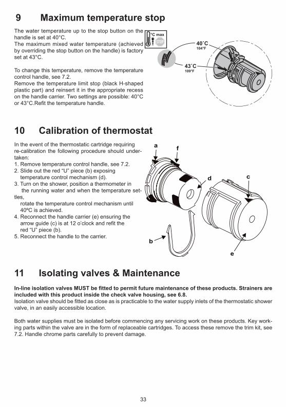
The water temperature up to the stop button on the handle is set at 40°C.The maximum mixed water temperature (achieved by overriding the stop button on the handle) is factory set at 43°C.
To change this temperature, remove the temperature control handle, see 7.2.Remove the temperature limit stop (black H-shaped plastic part) and reinsert it in the appropriate recess on the handle carrier. Two settings are possible: 40°C or43°C.Refitthetemperaturehandle.
In the event of the thermostatic cartridge requiringre-calibration the following procedure should under-taken:1. Remove temperature control handle, see 7.2.2. Slide out the red “U” piece (b) exposing temperature control mechanism (d).3. Turn on the shower, position a thermometer in the running water and when the temperature set-tles, rotate the temperature control mechanism until 40ºC is achieved.4. Reconnect the handle carrier (e) ensuring thearrowguide(c)isat12o’clockandrefitthe red “U” piece (b).5. Reconnect the handle to the carrier.
In-line isolation valves MUST be fitted to permit future maintenance of these products. Strainers are included with this product inside the check valve housing, see 6.8.Isolationvalveshouldbefittedascloseasispracticabletothewatersupplyinletsofthethermostaticshowervalve, in an easily accessible location. Both water supplies must be isolated before commencing any servicing work on these products. Key work-ing parts within the valve are in the form of replaceable cartridges. To access these remove the trim kit, see 7.2. Handle chrome parts carefully to prevent damage.
9 Maximum temperature stop
10 Calibration of thermostat
11 Isolating valves & Maintenance
11.1 Commissioning & periodic checks.The following procedures should be carried out after installation and every 12 months after to ensure that the valve is functioning correctly.
Check that: 1. The application of the thermostatic valve matches the approved designation. 2. The supply pressures are within the recommended range for the application. 3. The supply temperatures are within the permitted range for the application and comply with the guidance for prevention of Legionella. 4. The mixed temperature is as required for the application.
Record: 5. Each hot and cold supply. (Make a note of the measuring device used). 6. The mixed water temperature at the outlet device.Isolate: 7. The cold supply to the mixing valve and record the mixed water temperature after about 5 seconds.The temperature should not exceed the value given in the table (2) below.
Table.2. A guide to maximum temperature sets.
Note: 46°C is the maximum mixed water temperature from a bath tap. The maximum temperature takes ac-count of the allowable temperature tolerances inherent thermostatic mixing valves and temperature loss in metal baths. It is not a safe bathing temperature for adults and children.
11.2 Frequency of regular servicingThe purpose of servicing regularly is to monitor the performance of changes in system and valve set up. This may require the need to adjust either the supply system or the valve. The product should be checked and tested 12 months after commissioning.
Firstly measure the water temperature at the shower outlet.
Carry out the cold water supply isolation test by isolating the cold water supply to the TMV, wait for 5 seconds ifwaterisstillflowingcheckthatthetemperatureisbelow45°C.Ifthereisnosignificantchangetothesetoutlet temperature (+/-2ºC or less change from the original settings) and the fail-safe shut off is functioning, then the valve is working correctly and no further service work is required.Notes:Aresidualflowispermittedduringthecommissioningortheannualverification(coldwatersupplyisolationtest), then this is acceptable providing the water temperature is no more than 2ºC above the designated outlet temperature.
To replace the thermostatic cartridge:ISOLATE WATER SUPPLIES FIRST, drain down the pipe work as much as possible.1. Prise out the handle cover (L -shaped) see 7.2.2. Remove handle screw.3. Pull off the temperature control handle.4. To remove the temperature handle carrier (grey plastic moulding), slide the black serrated lever clockwise and pull off. This will expose some of the thermostatic cartridge.5. Gently pull off the chromed shroud. The plastic moulding that supports the shroud may slide off with the shroud, if not, pull this moulding off too. This will expose the remainder of the thermostatic cartridge.Themouldingshouldhavetwoo-ringsfitted.
6. Unscrew cartridge with a 24mm A/F deep socket, expect some trapped water to escape.Replacethecartridgeifnecessary.Whenrefittingcartridge,donotovertighten,handtightenthefirstfewthreads,maximumtorque16Nm. ENSURE PARTS ARE REASSEMBLED IN THE CORRECT SEQUENCE. Refer to 7.2 for assembling handle.
To clean the screens remove the o-rings shownThe sreens will then slide off. When clean replace thesreens then the o-rings which should be lightly greased witha approved silicone grease(eg Kluber Unisilikon GBU2
36
Max 12Nm
13 Flow cartridge replacementToreplacetheflowcontrolcartridge,ISOLATEWATERSUPPLIESFIRST. Drain down the pipe work as much as possible.
1. Undo the grub screw that secures the handle.2.Pullofftheflowcontrolhandle&thiswillexposethecartridgespindle.3.Pullofftheflowcontrolshroud.Abrassringsupportstheshroud,pullthisbrassringofftoo.Itisretainedontheflowcontrolvalveusingasnapclip.Thiswillexposetheremainderoftheflowcontrolcartridge.Thebrassringshouldhaveano-ringfittedontheoutside&asnapringontheinside.4. Unscrew cartridge with a 17mm A/F deep socket, expect some trapped water to escape. Replace thecartridgeifnecessary.Whenrefittingcartridge,donotovertighten,handtightenthefirstfewthreads, maximum torque 12Nm.5.Theblackdrivespindle(sleeve)shouldberefittedtothenewcartridge. ENSURE PARTS ARE REASSEMBLED IN THE CORRECT SEQUENCE.
14 Diverter cartridge replacementTo replace the diverter cartridge, ISOLATE WATER SUPPLIES FIRST.Todrainoffsomeoffthewaterinsidethevalve-box,turndiverterhandletotubfill.
1. Undo the grub screw that secures the handle.2. Pull off the diverter handle & this will expose the cartridge spindle, see 7.3.3. Pull off the diverter shroud. A brass ring supports the shroud, pull this brass ring off too. It is retained onthediverterclampingbushusingasnapclip.Thebrassringshouldhaveano-ringfittedontheoutside& a snap ring on the inside. This will expose some of the diverter cartridge.4. Unscrew the diverter clamping bush with a 22mm A/F deep socket. This will release the plastic positional moulding & the diverter cartridge. Expect some trapped water to escape. Replace the diverter if necessary. 5.Theblackdrivespindle&positionalsleeveshouldberefittedtothenewcartridge(undothescrewfitted to the spindle).ENSURE PARTS ARE REASSEMBLED IN THE CORRECT SEQUENCE.See next page for set-by-step re-assembly information.Refer to 7.3 for assembling handle.
NOTE: If the outlet pipes from the valve-box have been reversed during installation,thisproblemcanbesolved(inotherwordsthetubfillconnectionhasbeenmadetothetopofthevalve-box).Removethedivertercartridgeasdetailedabove,thenrotateit180°&refit.Thecartridgelugwillfitinto the secondary hole (D) shown on the next page.
37
14 Diverter cartridge replacement cont’ To refit the diverter cartridge:
1. Rotate the diverter spindle fully clockwise. Orientate the diverter as shown to view the bottom. With the locating lug on the left, check that the lower diverter port is closed.
A D
2. Align the locating lug on the bottom of the diverter to the right hand hole in the valve casting (A). Slide the diverter into the bore & ensure the lug has been correctly located into hole A.
3. Slide the plastic positional moulding onto the diverter, engaging the hexagons on both parts. Ensure the moulding is orientated as shown above, observing that the pointer (B) is at the top.4. Slide the clamping bush into place & rotate the bush clockwisethusengagingthefirstfewthreads.Usea22mmA/Fdeepsockettotighten.Whenrefittingcartridge, do not over tighten the clamping bush, maximum torque 12Nm.5. Fit the positional sleeve onto the diverter spindle, ensure the pointer (C) is aligned to pointer (B). Both parts are splined, so the sleeve canberemovedrotated&refitteduntilalignmentisachieved.Oncealigned,pressthesleevefirmly.Thiswillforcethetwolugsontheblackmouldingtomoveapart thus allowing the sleeve past. The sleeve should bottom-out on the brass spindle & the lugs on the black moulding snap back into position thus trapping the sleeve.6.Confirmpointersarealignasshown(planview).Fittheblackdrivespindle&tightenthescrewtosecure. Reverse the sequence & reassemble the parts. ENSURE PARTS ARE REASSEMBLED IN THE CORRECT SEQUENCE.
15 Check-valve cartridge replacementTo replace the check valve cartridges: (ISOLATE WATER SUPPLIES FIRST)1. Remove all the chromed trim kit parts, see 7.1 & 7.2.2. This should expose the check-valve housings, see 6.8.3. Using a 15mm A/F socket undo the check-valve housings (x2), expect some trapped water to escape.4.Unclipthemouldingfromthebrasshousingtoreleasethecheck-valve&filtermesh.5. Clean or replace the parts & reassemble.6.Reversethesequence&re-fitthecheck-valvehousingsbackintothevalve-box. ENSURE PARTS ARE REASSEMBLED IN THE CORRECT SEQUENCE.
38
16 Spare partsA6536AA
FlowDirn
2
3
3
45
6
87
910
910
10
11
1213
14
15
16
1718
19
23
25
24
26
27
28
33
30
31
32
22
21
201
7
29
12
1
40
1 A963131NU*3 A 963 132 NU7 A 861 051 NU8 A 961 183 NU9 F 960 903 NU10 F960904NU*11 A 861 052 NU12 A 861 053 NU13 F 960 907 NU14 F 960 908 NU15 A 963 154 NU17 A 861 054 NU18 A 962 368 NU19 F 960 909 NU
20 A 960 183 NU21 A 963 196 NU23 F 960 910 AA24 F 960 911 AA25 F 960 912 NU26 A 861 055 AA27 A 962 880 AA28 A962878AA*
30 A 960 229 NU31 A 861 056 AA* Universal-Set - not all parts are needed
2
3
3
45
87
910
910
10
11
1213
14
1516
17
1819
2325
24
26
27
28
36
30
31
32
33
34
35
22
2120
1
7
29
12
1
40
A6655AA
39
1 A963131NU*3 A 963 132 NU7 A 861 051 NU8 A 961 183 NU9 F 960 903 NU10 F960904NU*11 A 861 052 NU12 A 861 053 NU13 F 960 907 NU14 F 960 908 NU15 A 962 848 NU17 A 861 057 NU19 A 962 481 NU21 A 962 368 NU
16 Spare parts cont.…
For more information on spare parts contact Armitage Shanks Customer care, see details on back page.
22 F 960 909 NU23 A 960 183 NU24 A 963 196 NU26 F 960 910 AA27 F 960 911 AA28 F 960 912 NU29 A 861 058 AA30 A 962 880 AA31 A962878AA*33 A 960 229 NU34 A 861 056 AA
* Universal-Set - not all parts are needed
40
17 Cleaning chrome surfaces
When cleaning chromed products use only a mild detergent, rinse & wipe dry with a soft cloth. Ideally clean after each use to maintain appearance.
Never use abrasive, scouring powders or scrapers. Never use cleaning agents containing alcohol, ammonia, hydrochloric acid, sulphuric acid, nitric acid,phosphoric acid or organic solvents. Use of incorrect cleaning products / methods may result in chrome damage which is not covered by the manufacturer’s guarantee.
REECE PRODUCT QUALITY GUARANTEEYou have purchased a product from Reece Australia Pty Ltd ABN 84 004 097 090 (“Reece”). This product is covered by a 5 year replacement product warranty and a 12 month warranty over spare parts and labour.
5 YEAR PRODUCT WARRANTY This warranty covers faults in the construction, material and assembly of finished products. Products which are within 5 years from the date of purchase, found upon inspection by an authorised Reece representative to be defective in construction, material or assembly, will be repaired or exchanged with an equivalent product free of charge. Replaced items become Reece’s property.
This warranty also covers any spare parts included under “Manufacturer’s Provisions” below.
Manufacturer’s ProvisionsThe following spare parts are covered by a 10 year warranty:
• Mixer Cartridge
ONE YEAR SPARE PARTS WARRANTYSpare parts other than those listed in the Manufacturer’s Provisions above which are within 1 year from the date of purchase found upon inspection by an authorised Reece representative to be defective in construction, material or assembly will be replaced free of charge. Replaced items become Reece’s property.
AVAILABILITY OF REPLACEMENT PRODUCTS AND SPARE PARTSAll replacement products and spare parts will be available for collection without charge to the customer at the nearest Reece branch to the customer’s location, or elsewhere as agreed between the customer and Reece.
LABOURThe labour for the replacement of products that are within one year from the date of purchase found upon inspection by an authorised Reece representative to be defective in construction, material or assembly, and in relation to all spare parts to which this warranty applies, will be supplied by Reece or the relevant supplier using licensed plumbers engaged by Reece or the relevant supplier
WARRANTY CONDITIONSThis warranty will apply only under all of the following conditions:
EXCLUSIONSTo the fullest extent permitted by law, Reece excludes all liability for damage or injury to any person, damage to any property, and any indirect consequential or other loss or damage.
CLAIM PROCEDUREForallwarrantyqueriescustomersaretocontactthebranchwhere the product was purchased. These details can be found on your purchase invoice.
General contact details for Reece are as follows:
Reece Australia Pty Ltd 118BurwoodHwy BurwoodVIC3125 +61392740000 [email protected]
The benefits given by this warranty are in addition to the other rights and remedies that consumers may have under the Australian Consumer Law and any other applicable laws.
Our goods come with guarantees that cannot be excluded under the Australian Consumer Law. You are entitled to a replacement or refund for a major failure and for compensation for any other reasonably foreseeable loss or damage. You are also entitled to have the goods repaired or replaced if the goods fail to be of acceptable quality and the failure does not amount to a major failure.
TAP-ARMITAGE-5Don’t risk it, use a licensed plumber.™