12
Underground waterproofing & tanking Description Tanking and water-protection of underground structures by bituminous membranes

Underground waterproofing & tankingDescription
Tanking and water-protection of underground structures by bituminous membranes

Icopal | 12, rue de la Renaissance - F-92 184 Antony CEDEX | Tel. : +33 1 40 96 35 00 - Fax : +33 1 40 96 35 07 | www.siplast-international.com2
Underground waterproofing & tankingPlease note:
The information in this guide is intended to serve as a general guideline,and as such does not take into account particular restrictions or requirements arising from unusual geographical or topographical situations, or non-standard construction configurations. This information does not release construction professionals from the need to be fully familiar with the reference documents and applicable standards and with the information contained in them, nor for reading the relevant documentation in full.
Introduction
Preventing the ingress of water or damp into underground premises is a problem often faced by building contractors. It needs to be taken into consideration from design stage onwards. The concerns are all the more complex as there are many possible sources of unwanted moisture:
The water table, whose level may vary ( rainfall, or high water levels in neighbou- �
ring water courses), causing water to rise above the lowest level of the building underground.Groundwater runoff against or infiltration into the outer walls of the underground �
part of buildings. In mountainous regions in particular, underground sources of water can project massive quantities of water against the outer walls of buildings, both above and below ground. Damp capillary rise, which can lead to water rising up walls up to the level of the �
residential quarters of a building when in contact with and under the pressure of water-laden soil. Wind-blown rain on building facades, which can penetrate through the walls and, �
depending on the building structure, reach the inner surfaces of underground walls under the force of gravity or by capillary attraction.Condensation of the water vapour contained in moist air in contact with walls that �
are cold (because insufficiently insulated), in rooms or premises that are insuffi-ciently ventilated.Accidental leakage or spillage from water pipes (water supply, heating water), �
especially when the pipes are built into the building structure.
The last three factors are not the result of groundwater seepage through the surrounding walls of a building. But the first three situations can be remedied by adequate waterproofing or water-protection systems.
This Siplast-Icopal guide proposes definitions of the technical solutions potentiall-most suitable to each of the above three situations.
Contents
Introduction 2
Definitions: soils, walls, building works 3
Underground construction work and its relation to groundwater levels 4
Solutions for treatment of underground walls 6
Damp courses 9
Tanking 10

3Icopal | 12, rue de la Renaissance - F-92 184 Antony CEDEX | Tel. : +33 1 40 96 35 00 - Fax : +33 1 40 96 35 07 | www.siplast-international.com
Foundation soils
The manner in which the foundations of a building are designed depends on the nature of the soils surrounding and supporting them, and on the variations in that soil. A principal characteristic of any soil is its loadbearing ability. The presence of water in the soil in contact with or surrounding the foundations, and in the layers of soil actually suppor-ting the foundations, may have an effect on the soil’s loadbearing ability.
Soil survey
The loadbearing ability of a soil is assessed through a soil survey, giving rise to recommendations for the most appropriate foundations. The survey will also determine the levels and type of underground water or moisture content in the soil in the vicinity of the foundations, so as to identify the most appropriate treatment of the walls and foundations. An examination of the site and study of geological maps generally enables specialists to make an initial assessment of soil types.
Soil investigation is done by core sam-pling within and around the perimeter of the future building. The samples are then analysed on site (static or dynamic penetrometer, pressure meter, table testing), completed if necessary by la-boratory testing. The purpose of these tests is to measure the permeability and water content of the soil.
The foundations
The foundations are intended to support the weight of the building and should be designed to withstand the stresses arising from the superstructure when affected by wind forces, and the defor-mation of the substructure caused by the soil and its movement. Depending on the nature of the soil, the founda-tions will be dug to greater or lesser depth.
Shallow foundations are employed when satisfactory soil conditions are
found close to the surface. Such foun-dations are made up of:
Either a strip foundation poured on �
site, or prefabricated, either running extensively under the walls in sup-port, or laid at intervals;Or a general raft foundation, for soil �
of low loadbearing characteristics, or when building takes place on com-pacted infill.
Deeper foundations are used when the upper layers of the soil cannot support the building. They may be made up either of concrete posts interconnected by girders, or of bores drilled down to a higher loadbearing soil layer supporting the masonry work by means of girders, or by piles whose cross section is smal-ler than the bore, and driven in by spe-cialist contractors, which support the superstructure by the force of friction of the soil against the sides of the piles.
Drainage
Drainage is necessary to prevent the unwanted build-up of water in contact with the walls under the soil surface, in particular for buildings resting on a relatively impermeable level of subsoil covered by more permeable levels of topsoil.
Ring drainage is the basic technique used to surround the building and protect it by channelling away ground-water that would otherwise accumu-late. Drainage may also be designed to direct away from the building the water collecting from draining systems under surface surface slabs adjacent to the building, taking the water away to larger culverts, mains drainage networks, or possibly to a drainage pit.
Drainage becomes unnecessary or inef-ficient in the following conditions:
The soil is subject to a water table of �
variable level, which is liable to rise above the level of the lowest of the basement floors;Build up of water may take place �
over relatively long periods along
perimeter walls. This will arise when the building’s foundations are laid in relatively impermeable soil, in which case the water collected by an un-derground draining system cannot be satisfactorily dispersed away from the building.
In both cases, arrangements must be made to avoid flooding the underground building enclosures. This requires tanking. The drainage may be inade-quate, and even dangerous, if impro-perly designed in certain cases, such as non-homogeneous soils. These soils cause the water to drain into permeable veins of underground soil which may absorb considerable quantities of water, which cannot then be discharged, once saturation point has been reached. In this case, the subsoil may become uns-table, particularly when the land is on an incline.
Here again, the fact that drainage can-not sustainably protect a building will be a reason for investigating the suita-bility of a tanking solution. The design of drainage networks and drainage trench work needs to comply with local standards.
Backfill
The type of filler earth and the way it can be used to build up layers of soil for compaction or other forms of embankment are generally described in local standards.
Filler soil of homogeneous characte-ristics is laid in one or more horizontal layer, each of thickness no more than 0.20 m before compaction.
Compliance to this requirement is important, particularly when the walls of the building are to be protected by waterproof sheeting, film, coating or equivalent.
It may be dangerous to backfill with very permeable soil an open trench dug for foundations, when they are laid over soil which is relatively impermeable, un-less protective drainage is provided.
Definitions: soils, walls, building works

Icopal | 12, rue de la Renaissance - F-92 184 Antony CEDEX | Tel. : +33 1 40 96 35 00 - Fax : +33 1 40 96 35 07 | www.siplast-international.com4
Underground waterproofing & tanking
Level W
Above level W Below level W
Level W
1 Hydrostatic pressure pressure on walls
2 Action of waters without on walls
Combination of skills
The protection of underground walls against the action of water is a complex matter in design terms. This is because there are many possible sources of water, and many factors liable to play a part in the choice of the right solu-tion. Among these are the hydraulics of underground water, nature of soil, type of foundations, nature and thickness of walls, the intended and actual use of the building interior …
These factors play a major role in the determination of the type of outer coating required and the associated construction techniques. Many persons are involved and play a critical role. Among those concerned are:
Building or project Owner, who must �
define the nature of the construction and requirements in respect of the presence or absence of damp, and the degree of reliability sought in pro-tection against it.The main contractor who is required �
to determine the nature of the foun-dation soil and degree of exposure of the building to groundwater, in the light of the known levels of high water, topographical environment and climate.The specialised sub-contractor �
who either alone, or with the main contractor, makes the choice of types of walls.
All these criteria interact. Consequently, the proper protection of underground walls involves the input of skills from all these areas.
Work is permanently and in whole above water level ( 2 )
Consequence :The land is not saturated in water, �
and water is in contact with the walls of the construction without exerting pressure on them ;The action of water is limited to mo- �
vement by capillary attraction .
The protection of the construction will then require:
Surface treatment of underground �
walls;Damp course to cut of damp ca- �
pillary rise at the top of the foun-dation walls.
Please consult chapter “Protection and drainage of underground walls” or chapter “Damp course”* Except if the specifications state the need for tanking by application of a waterproof coating. If so, please chapter on Tanking.
The underground construction and its relationship to the standard level of groundwater W, conditions the way in which protection is provided :
For water table or high surface water �
levels: W > the level of the highest known or forecast level of water.For subsurface runoff or water seepa- �
ge: W > level of the water stream in the drainage courses or natural level of water seepage through permeable soil layers + 0.50 m.
Construction is immersed in whole or in part, even on an intermittent basis ( 1 )
Consequence :All the voids in the soil are filled with water, which puts the walls of the construction under pressure.
The waterproofing is then provided by tanking techniques.
These techniques are defined in local standards about tanking.Please consult chapter on « Tanking ».
Underground construction work and its relation to groundwater levels

5Icopal | 12, rue de la Renaissance - F-92 184 Antony CEDEX | Tel. : +33 1 40 96 35 00 - Fax : +33 1 40 96 35 07 | www.siplast-international.com
Solutions for treatment of underground walls
Solution 1
Fondacoat®
Bituminous liquid coating for waterproofing concrete or masonry wall
Masonry wall compliant to local standards
Mortar rendering compliant to local standards
Fondacoat
Backfill material compliant to local standards
Concrete wall compliant to local standards
Fondacoat
Backfill material applied compliant to local standards
Comments: this coating may be completed (solutions 1 + 5 and 1 + 6) by Fonda + protection
(see solution 5) or by a Fonda GTX protection and drainage membrane (see solution 6).
In this case, the backfill is not in direct contact with Fondacoat
Solution 2
Fondaplast® EThick waterproofing bituminous coating for masonry wall without preliminary coating or rendering
Plane masonry wall, bare pointing (mortar joints) between elements
Fondaplast E
Backfill material applied compliant to local standards.
Comments: this coating may be completed (solutions 2 + 5 and 2 + 6) by a Fonda + protection membrane (see solution 5) or by the Fonda GTX drainage and protection membrane (see solution 6).
In this the backfill material is not in direct contact with Fondaplast E.
The nature of the elements making up the masonry wall and their thickness must comply with local standards. The wall elements must be plane and perfectly uniformly pointed.
Masonry of autoclaved cellular concrete blocks absolutely must be coated.

Icopal | 12, rue de la Renaissance - F-92 184 Antony CEDEX | Tel. : +33 1 40 96 35 00 - Fax : +33 1 40 96 35 07 | www.siplast-international.com6
Underground waterproofing & tanking
Solution 3
Adeti Premium ® Underground wall coating of strong, smooth, self-adhesive bituminous membrane
Nature of wall
Maçonnerie non enduite jointoyée au nu des éléments
Maçonnerie enduite au mortier de ciment
Mur en bétonMaçonnerie non enduite jointoyée au nu des éléments
Maçonnerie enduite au mortier de ciment
Mur en bétonMaçonnerie non enduite jointoyée au nu des éléments
Maçonnerie enduite au mortier de ciment
Mur en bétonUnrendered masonry, bare pointing between elements
Masonry rendered in cement mortar Concrete wall
Principles of application
or
Height 3 m
Wall
Cold application Veral coating or Siplast Primer
Adeti Premium
Backfill compliant to local standards
Top fixing (4 units per strip)
Upper strips to lap over lower strips
Adeti Premium
Mortar edging
Angle, extension 0.25 m in Adeti Premium
After cold application and drying of coating (Siplast Primer), Adeti Premium is applied in the vertical plane with 6 cm sidelap, self-adhesion by removing peel-off film on underside, bonding under pressure. Mechnical fixing at top of strip applied as work progesses. Upper strips overlap mechanical fixing of the lower selvedges.
Comments: Uncoated masonry joints must be carefully finished in smooth mortar pointing flush with elements.Mortar rendering must be finely floated. Adeti Premium may be completed by a Fonda + protection membrane (see solution 5) or by Fonda GTX drainage and pro-tection membrane (see solution 6).Adeti Premium has a smooth, strong surface. However, in certain cases, an additio-nal layer of protection may be necessary.Gravifiltre may further improve the compaction of backfill material.

7Icopal | 12, rue de la Renaissance - F-92 184 Antony CEDEX | Tel. : +33 1 40 96 35 00 - Fax : +33 1 40 96 35 07 | www.siplast-international.com
Solution 4
FondaforUnderground wall protection by torched SBS-modified bituminous membrane
Nature of wall
Maçonnerie non enduite jointoyée au nu des éléments
Maçonnerie enduite au mortier de ciment
Mur en bétonMaçonnerie non enduite jointoyée au nu des éléments
Maçonnerie enduite au mortier de ciment
Mur en bétonMaçonnerie non enduite jointoyée au nu des éléments
Maçonnerie enduite au mortier de ciment
Mur en bétonUnrendered masonry, bare pointing between elements
Masonry rendered in cement mortar Concrete wall
Principle of application
or
Height 3 m
Wall
Cold application Veral coating or Siplast primer
Fondafor
Backfill compliant to local standards 5
Top fixing (4 units per selvedge)
End lap of top selvedges over lower selvedges
Fondafor
Mortar edging
Angle, extension 0.25 m in Adeti Premium
After cold application and drying of coa-ting (Impression Veral or Siplast Primer), Fondaply 2 is applied vertically with 6 cm sidelap, self-adhesion by removing peel-off film on underside, bonding under pressure. Mechnical fixing at top of strip applied as work progesses. Upper strips overlap the mechanical fixing of the lower selvedges
Comments: Uncoated masonry joints must be carefully finished in smooth mortar pointing flush with elements. Mortar rendering should be finely floated. Fondafor may be completed by Fonda + protection membrane (see solution 5) or by Fonda GTX drainage and protection membrane (see solution 6).Fondafor has a smooth and strong surface. However, in certain cases, additional protection may be necessary. Gravifiltre may furthur improve the compaction of the backfill material

Icopal | 12, rue de la Renaissance - F-92 184 Antony CEDEX | Tel. : +33 1 40 96 35 00 - Fax : +33 1 40 96 35 07 | www.siplast-international.com8
Underground waterproofing & tanking
Solution 5
Fonda® +Protection of underground walls by studded HDPE membrane and octagonal studs.
Principles of application
Fonda + available in 1 m, 1,50 m, 2 m or 2,50 m wide rolls.Horizontal roll out, studs against wall. As work progresses, top fixing:
On masonry walls by Fonda nails and wall plugs; �
On concrete walls by standard nails and Fonda concrete �
washers Hilti (cartridge pistol and 20 to 27 mm pins). When the height of the wall to be protected is greater than the width of the roll, Fonda + upper selvedge overlaps the lower sel-vedge by around 12 cm.Vertical endlap around 50 cm..
Masonry wall compliant to local standards or poured concrete wall compliant to DTU 23.1
In certain cases (see page 10): waterproof coating or membrane (solutions 1, 2, 3 or 4)
Fonda + protection membrane
Fonda HDPE or PVC moulding
Fonda + membrane fixing by nails or Fonda wall plugs
Fonda moulding applied
Solution 6
Fonda® GTXProtection and drainage of underground walls by stud-ded HDPE membrane, including drainage geotextile.
Principles of application
Fonda GTX available in 2 m wide rolls, horizontal roll out, filter on filler-earth side, top selvedge fixed as work progresses:
On masonry walls, by Fonda pins and wall plugs; �
On concrete walls, by Fonda concrete washers and Hilti �
pins (cartridge pistol and 20 to 27 mm pins). When the height of wall protention is more than 2 m, GTX sidelap of top strip over bottom is12 cm.
Vertical endlap around 50 cm.
Masonry wall compliant to local standards.1 or poured concrete wall compliant to local standards
In certain cases : waterproofing material or membrane is used (solutions 1, 2, 3 or 4)
Fonda GTX protection and drainange membrane
Fonda HPDE or PVC moulding
Perimeter drainage around construction compliant to local standards.
Overlaid by Fonda GTX moulding
Fonda moulding applied
9Icopal | 12, rue de la Renaissance - F-92 184 Antony CEDEX | Tel. : +33 1 40 96 35 00 - Fax : +33 1 40 96 35 07 | www.siplast-international.com
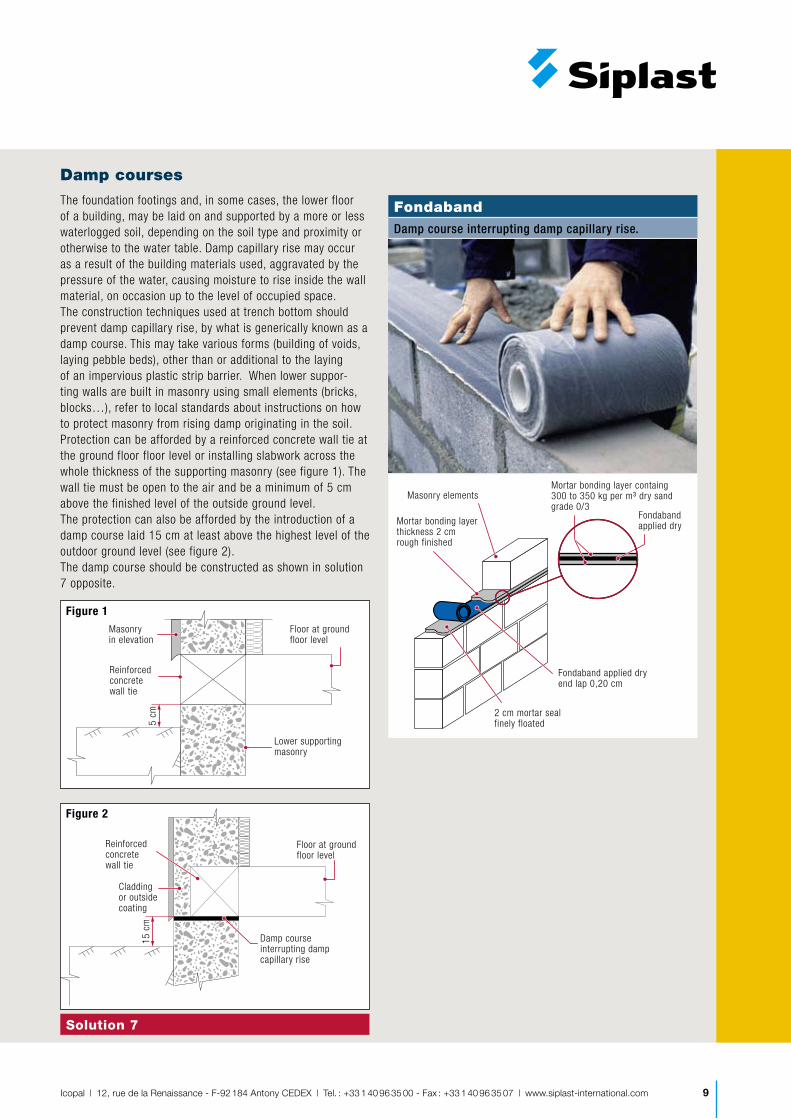
Damp courses
The foundation footings and, in some cases, the lower floor of a building, may be laid on and supported by a more or less waterlogged soil, depending on the soil type and proximity or otherwise to the water table. Damp capillary rise may occur as a result of the building materials used, aggravated by the pressure of the water, causing moisture to rise inside the wall material, on occasion up to the level of occupied space.The construction techniques used at trench bottom should prevent damp capillary rise, by what is generically known as a damp course. This may take various forms (building of voids, laying pebble beds), other than or additional to the laying of an impervious plastic strip barrier. When lower suppor-ting walls are built in masonry using small elements (bricks, blocks…), refer to local standards about instructions on how to protect masonry from rising damp originating in the soil.Protection can be afforded by a reinforced concrete wall tie at the ground floor floor level or installing slabwork across the whole thickness of the supporting masonry (see figure 1). The wall tie must be open to the air and be a minimum of 5 cm above the finished level of the outside ground level.The protection can also be afforded by the introduction of a damp course laid 15 cm at least above the highest level of the outdoor ground level (see figure 2).The damp course should be constructed as shown in solution 7 opposite.
Lower supportingmasonry
5 cm
Floor at groundfloor level
Reinforcedconcretewall tie
Masonry in elevation
Figure 1
15 c
m
Floor at groundfloor level
Reinforcedconcretewall tie
Damp courseinterrupting dampcapillary rise
Claddingor outsidecoating
Figure 2
Solution 7
FondabandDamp course interrupting damp capillary rise.
Masonry elements
2 cm mortar sealfinely floated
Fondaband applied dryend lap 0,20 cm
Fondaband applied dryMortar bonding layer
thickness 2 cm rough finished
Mortar bonding layer containg 300 to 350 kg per m³ dry sand grade 0/3

Icopal | 12, rue de la Renaissance - F-92 184 Antony CEDEX | Tel. : +33 1 40 96 35 00 - Fax : +33 1 40 96 35 07 | www.siplast-international.com10
Underground waterproofing & tanking
Depending on a number of criteria, including the purposes and fit-out of the premises, their conditions of use, the conditions of access to and maintenan-ce of the tanking, the action of water, and the more or less suitable on site conditions, contractors will in general opt for one of the three types of tanking described below.
Three types of tanking
Tanking with waterproof coating
The waterproof coating consists of an inner film or waterproof coat adhering to its substarate, without any notable resistance to cracking in that substrate. The protective coating is made of wa-ter-repellent water or resin-based film coating, or by a mineral-based surface application.
Tanking surrounds the whole of the perimeter of the building directly in contact with groundwater and the connected adjacent inner portions, known as returns. In most cases a top-coat is applied to the tanking coat.
The technical rules governing the de-sign calculation of the structural work (including outer perimeter and possibly returns) are usually determined in local standards.
Tanking with partial waterproofing
Tanking of this kind does not require the application any coating or rendering over it. Accordingly, a degree of per-meability to water seepage through the walls is acceptable. The limits are:
For the building perimeter: �
annual average seepage: �
0,5 l/m²/day. weekly average seepage: �
1,0 l/m²/day.For any 10 m² portion of the peri- �
meter making up a rectangle whose two sides measure less than 5 m, a weekly average seepage of 2,0 l/m²/day.
The conditions of use of the premises should make allowance for this partial degree of waterproofing of the building perimeter. Hence facilities should be provided to collect seepage water, pro-vide ventilation etc.
The technical rules for the design and calculation of the structural work in this layout are usually determined in local standards.
For drainage and ventilation on the inside of underground walls (walls and floors): Fonda + (see above ins-tructions Fonda + /solution 5 )
Tanking with waterproofing membrane:
The tanking is performed with the Teranap TP Tanking System, a com-prehensive system featuring Teranap 431TP,elastomeric bitumen extra wide (2 m or 4 m wide) geomem-brane, Parafor M3S covering strip on overlaps and Terasop waterbar for compartmentalization.
The double protection of Teranap 431TP by polyester film surfacing and thick po-lyester reinforcement allows for loose-laid application to the outer surfaces of the structure, withstanding permanent water pressure (up to 7 bars).
The tanking is completed either by:Outer construction: � 1 and 2 ,Or by an internal construction ele- �
ment whose main function is to withstand the forces exerted by water pressure: 3
Arrangements 1 and 3 are adopted on permanent shuttering, i.e.,when there is no possibility of action outside the construction limits. The waterproofing process is applied in a one-off applica-tion on horizontal and vertical surfaces.
Arrangement 2 is adopted when the waterproofing process is applied on the outer surface of the structural walls. The waterproofing process is then ap-plied in two phases:
Horizontal waterproofing during the �
preparatory work on the raft (prior to the construction of the internally supportive structural work).Vertical waterproofing on the inter- �
nally supportive structural work itself.
Internal supportive structure
Level W
Raft preparatorysubstructure
Perimeter walls
1 Tanking with permanent shuttering (outer structural walls non accessible)
Internal supportive structure
Level W
Raft preparatorysubstructure
Protection work
2 Tanking on outer structural walls
External supportive structure
Internal supportivestructure
Lewel W
3 Tanking with permanent shuttering (outer structural walls non accessible)
Tanking

11Icopal | 12, rue de la Renaissance - F-92 184 Antony CEDEX | Tel. : +33 1 40 96 35 00 - Fax : +33 1 40 96 35 07 | www.siplast-international.com
Tanking with permanent shuttering ( outer structural walls non accessible)
Teranap 431 TP geomembrane loose-laid with torched side-laps and end-laps, mechanically-fixed on top.
Mechanical protection. Horizontally: geotextile or LDPE membrane. 2.bis Vertically: Fonda + protection layer.
Perimeter concrete wall
Internal supportive structure withstanding hydrostatic pressure
Concrete screed (mini 5 cm thick)
Raft preparatory substructure
Tanking on outer structural walls
L 1st step: horizontal waterproofing
Teranap 431 TP geomembrane loose-laid with torched side-laps and end-laps.
Mechanical protection: geotextile or LDPE membrane.
Concrete screed (mini 5 cm thick)
Internal supportive structure
Raft preparatory substructure
L 2nd step: vertical waterproofing
Teranap 431 TP geomembrane loose-laid with torched side-laps and end-laps, mechanically-fixed on top.
Mechanical protection. Horizontally: geotextile or LDPE membrane
Teranap 431 TP geomembrane fully torched
Mechanical protection
Siplast Primer
Concrete screed
Internal supportive structure
Raft preparatory substructure
Remarks: once applied the Teranap 431 TP waterproofing geomembrane, it is necessary to add a mechanical protection before backfilling.
Such type of tanking can only be completed if the outer walls are accessible.

B4-6
5 |
12/0
8 |
Phot
os :
Icop
al |
R.C
.S. N
ante
rre
B 55
2 10
0 98
4
12, rue de la Renaissance 92184 Antony Cedex Tél. +33 (0)1 40 96 35 00 Fax. +33 (0)1 40 96 35 07 www.siplast.fr
System Brochure 6 - Edition 1


