6 Wa Density and Sheath Material Selecon – Selecng the proper wa density and the proper sheath material is crical to heater life and, if applicable, fluid integrity. If the wa density is too high, the fluid may carbonize, break down chemically, or the elements may burn out. If the wa density is too low the heater price will be high. The greatest heater life will come from the lowest wa density prac- cal for the applicaon. In general, wa density is determined by three factors: 1) maximum outlet temperature 2) type of fluid heated and 3) fluid flow rate Sheath material depends on the type of fluid and maximum tem- perature. If the sheath material selecon is incorrect, it will corrode, destroying the element Heang Air and Other Gases – Charts A through C give maximum sheath temperatures for a range of wa densies and velocies. This data is based upon air at atmospheric pressure and a 75°F inlet air temperature. For higher inlet temperatures, the sheath temperature will increase accordingly. Contaminants in the air, while normally not affecng the sheath temperature, may require a more highly corro- sion-resistant sheath and/or fin material. For heang compressed air and other gases, consult the factory or your local Heatrex represen- tave for wa density and sheath recommendaons. Watt Density & Sheath Selection Wa Density – Wa density is one of the most crical factors affect- ing element life. Wa density, expressed in was per square inch of heater surface area, determines the heater operang temperature for a given set of condions. The sheath temperature of an electric heang element should be limited to provide a reasonable heater life and to avoid possible damage of the medium being heated. We can esmate the sheath temperature or select the appropriate wa density based on the charts and tables provided. Wa density is calculated as follows: Wa Density = element waage/3.14 x element diameter (inches) x heated length (inches) An example is: An 8 kW flange heater has three 0.475” diameter elements with a “B” dimension of 47 inches and a 2 inch cold end. The wa density is: 0.475 x 3.14 x (47 in. - 2 in.) x 3 (# of elements) x 2 (u-bend) = 403 in2 8,000 Was ÷ 403 in2 = 20 W/in2 Sheath Material – Also crically important, the sheath material must be suitable for the corrosive condions and the extreme tempera- tures of the applicaon. Copper sheathed elements are typically used for low temperature applicaons such as heang water and some aqueous soluons. Steel is generally used with oil heang applicaons. Stainless steel and INCOLOY® are used when heang corrosive soluons or high-temperature gas/air. Table I and II list the maximum recommended operang temperatures for common sheath materials.
Transcript
6
Watt Density and Sheath Material Selection – Selecting the proper watt density and the proper sheath material is critical to heater life and, if applicable, fluid integrity. If the watt density is too high, the fluid may carbonize, break down chemically, or the elements may burn out. If the watt density is too low the heater price will be high. The greatest heater life will come from the lowest watt density prac-tical for the application.
In general, watt density is determined by three factors:1) maximum outlet temperature2) type of fluid heated and3) fluid flow rate
Sheath material depends on the type of fluid and maximum tem-perature. If the sheath material selection is incorrect, it will corrode, destroying the element
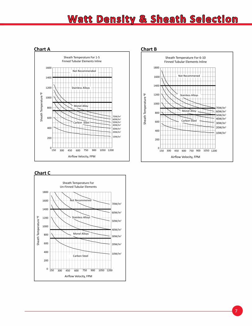
Heating Air and Other Gases – Charts A through C give maximum sheath temperatures for a range of watt densities and velocities. This data is based upon air at atmospheric pressure and a 75°F inlet air temperature. For higher inlet temperatures, the sheath temperature will increase accordingly. Contaminants in the air, while normally not affecting the sheath temperature, may require a more highly corro-sion-resistant sheath and/or fin material. For heating compressed air and other gases, consult the factory or your local Heatrex represen-tative for watt density and sheath recommendations.
Watt Density & Sheath Selection
Watt Density – Watt density is one of the most critical factors affect-ing element life. Watt density, expressed in watts per square inch of heater surface area, determines the heater operating temperature for a given set of conditions. The sheath temperature of an electric heating element should be limited to provide a reasonable heater life and to avoid possible damage of the medium being heated. We can estimate the sheath temperature or select the appropriate watt density based on the charts and tables provided.
Watt density is calculated as follows: Watt Density = element wattage/3.14 x element diameter (inches) x heated length (inches)
An example is:An 8 kW flange heater has three 0.475” diameter elements with a “B” dimension of 47 inches and a 2 inch cold end. The watt density is:
0.475 x 3.14 x (47 in. - 2 in.) x 3 (# of elements) x 2 (u-bend) = 403 in2
8,000 Watts ÷ 403 in2 = 20 W/in2
Sheath Material – Also critically important, the sheath material must be suitable for the corrosive conditions and the extreme tempera-tures of the application. Copper sheathed elements are typically used for low temperature applications such as heating water and some aqueous solutions. Steel is generally used with oil heating applications. Stainless steel and INCOLOY® are used when heating corrosive solutions or high-temperature gas/air. Table I and II list the maximum recommended operating temperatures for common sheath materials.
7
Watt Density & Sheath Selection
Chart A Chart B
Chart C
Sheath Temperature ForUn-Finned Tubular Elements
Shea
th Te
mpe
ratu
re 0F
Airflow Velocity, FPM
Not Recommended
0
200
400
600
800
1000
1200
1400
1600
1800
150 300 450 600 750 900 1050 1200
70W/In2
60W/In2
50W/In2
40W/In2
30W/In2
20W/In2
10W/In2
Not Recommened
Stainless Alloys
Monel Alloys
Carbon Steel
1500
200
400
600
800
300 450 600 750 900 1050
1000
1200
1400
1600
1800
1200
0
100
200
300
400
500
600
700
800
900
1000
1100
1200
1300
1400
1500
1600
1700
1800
150 300 450 600 750 900 1050 1200Sh
eath
Tem
pera
ture
, °F
Airflow Velocity, FPM
Sheath Temperature For 6-10 Finned Tubular Elements Inline
Sheath Temperature For 6-10Finned Tubular Elements Inline
Shea
th Te
mpe
ratu
re 0F
Airflow Velocity, FPM
70W/In2
60W/In2
50W/In2
40W/In2
30W/In2
20W/In2
10W/In2
Stainless Alloys
Monel Alloy
Carbon Steel
Not Recommened
150 300 450 600 750 900 1050 12000
200
400
600
800
1000
1200
1400
1600
1800
Sheath Temperature For 1-5Finned Tubular Elements Inline
Shea
th Te
mpe
ratu
re 0F
Airflow Velocity, FPM
0
100
200
300
400
500
600
700
800
900
1000
1100
1200
1300
1400
1500
1600
150 300 450 600 750 900 1050 1200
Shea
th T
empe
ratu
re, °
F
Airflow Velocity, FPM
Figure BSheath Temperature For Single Finned Tubular Element
70W/In2
60W/In2
50W/In2
40W/In2
30W/In2
20W/In2
10W/In2
Stainless Alloys
Monel Alloy
Carbon Steel
Not Recommended
150 300 450 600 750 900 1050 12000
200
400
600
800
1000
1200
1400
1600
8
Watt Density & Sheath Selection
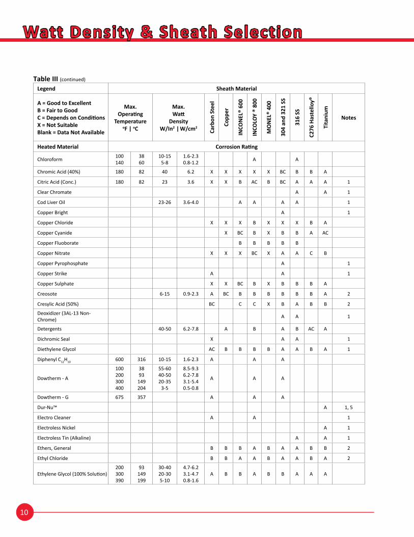
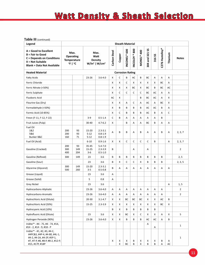
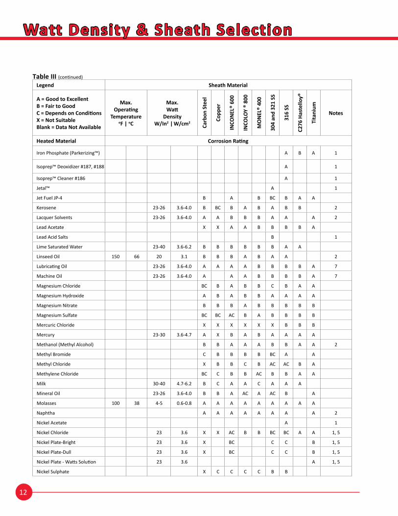
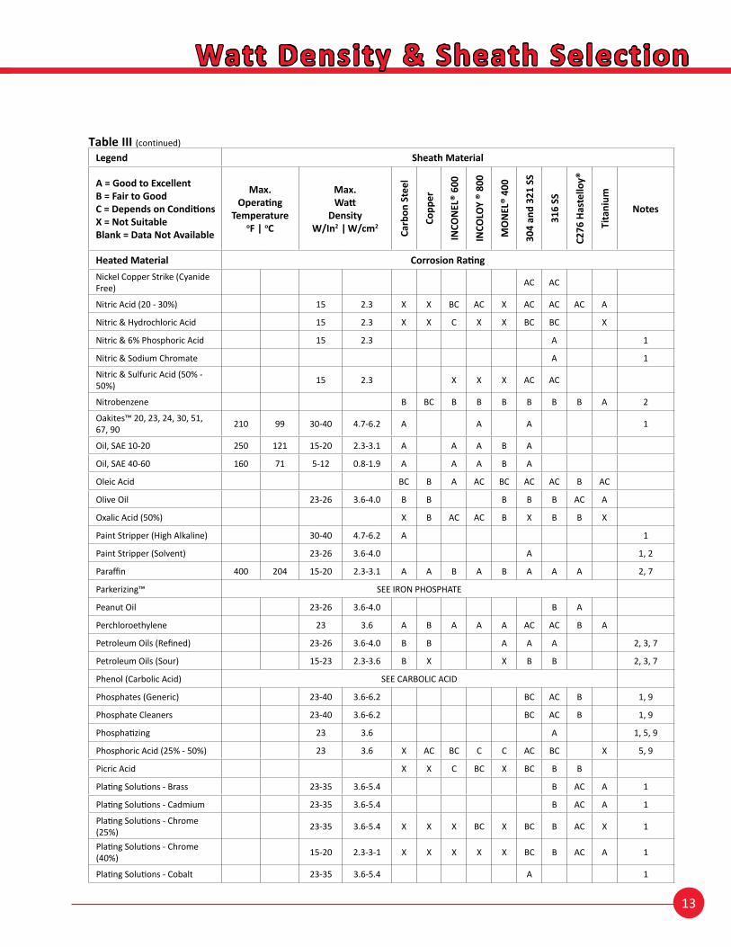
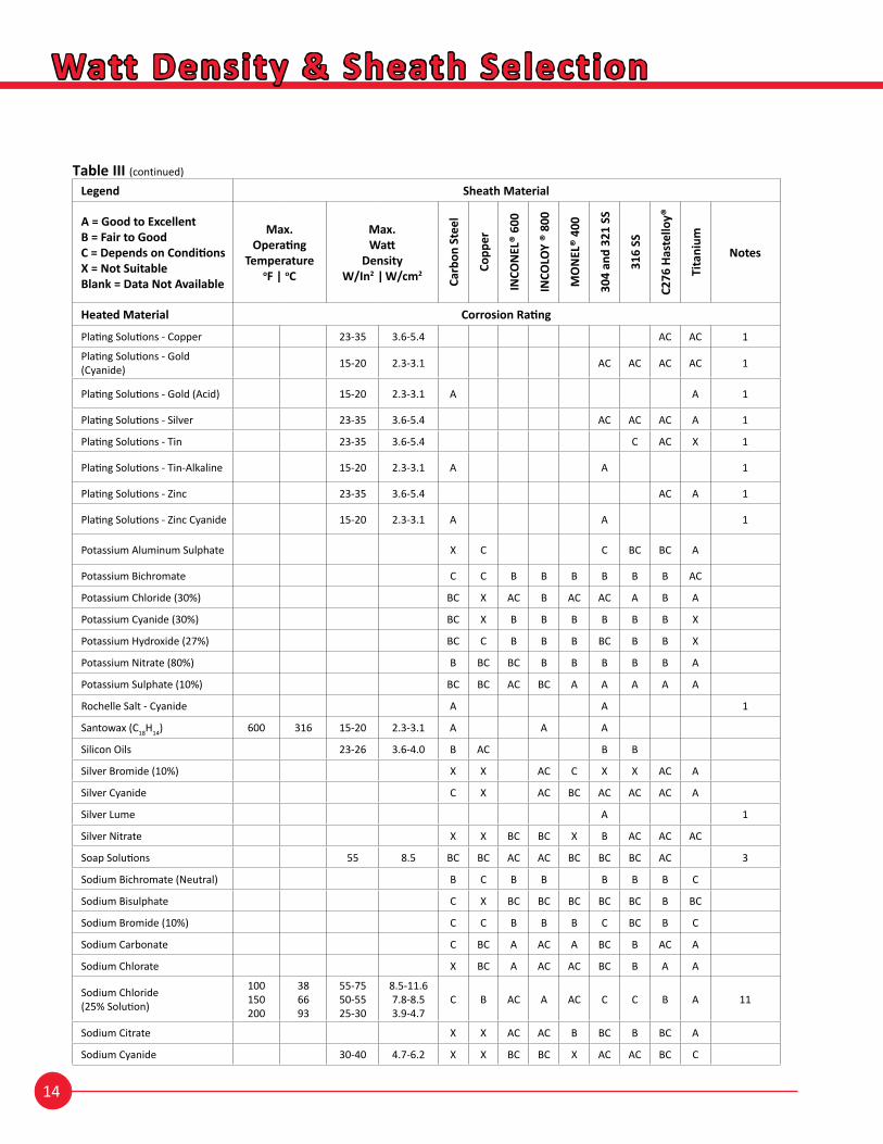
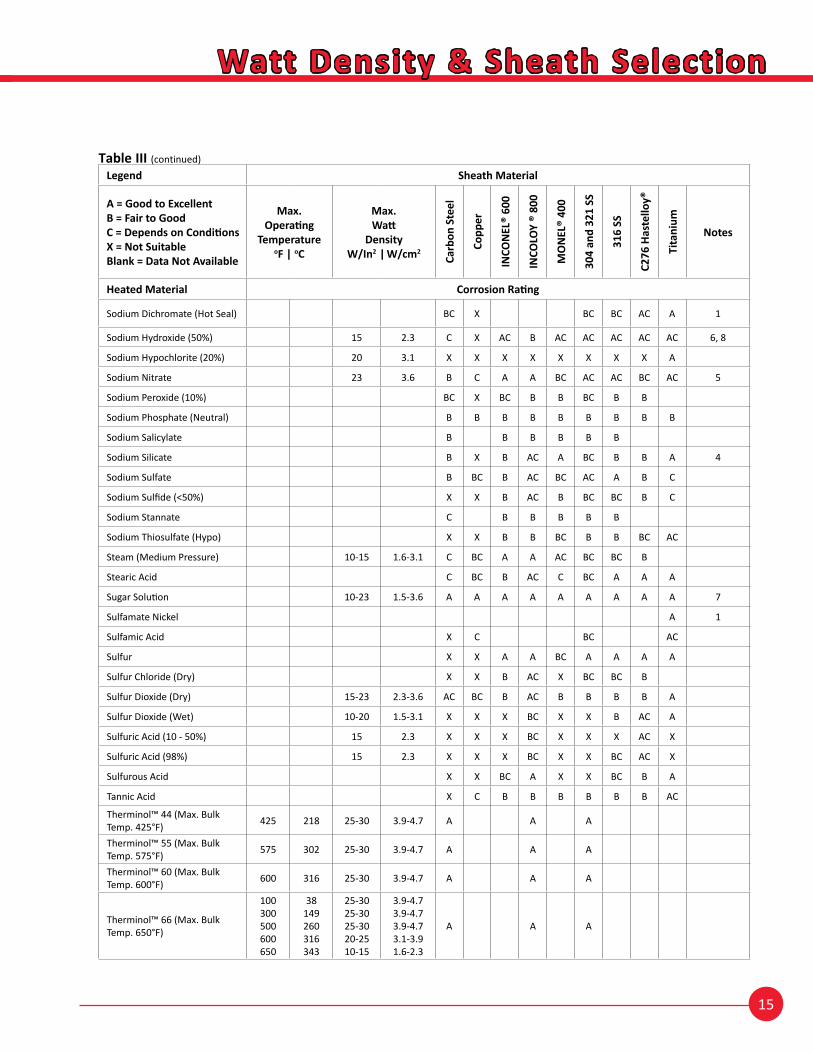
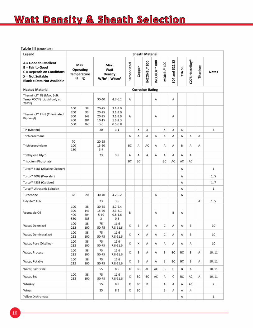
Table III
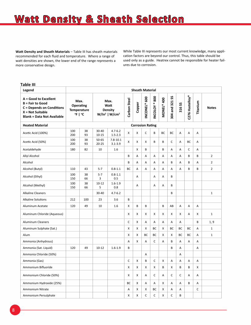
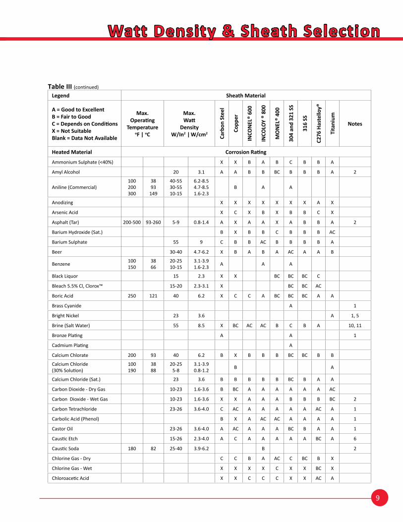
Watt Density and Sheath Materials – Table III has sheath materials recommended for each fluid and temperature. Where a range of watt densities are shown, the lower end of the range represents a more conservative design.
While Table III represents our most current knowledge, many appli-cation factors are beyond our control. Thus, this table should be used only as a guide. Heatrex cannot be responsible for heater fail-ures due to corrosion.
Legend Sheath Material
A = Good to ExcellentB = Fair to GoodC = Depends on ConditionsX = Not SuitableBlank = Data Not Available
Max.Operating
TemperatureoF | oC
Max.Watt
DensityW/In2 | W/cm2
Carb
on S
teel
Copp
er
INCO
NEL
® 60
0
INCO
LOY
® 80
0
MO
NEL
® 40
0
304
and
321
SS
316
SS
C276
Has
tello
y®
Tita
nium
Notes
Heated Material Corrosion Rating
Acetic Acid (100%) 100200
3893
30-4010-15
4.7-6.21.5-2.3 X X C B BC BC A A A
Acetic Acid (50%) 100200
3893
50-6520-25
7.8-10.13.1-3.9 X X X B B C A BC A
Acetaldehyde 180 82 10 1.6 X B B A A C A
Allyl Alcohol B A A A A A A B B 2
Alcohol B A A A A B A B A 2
Alcohol (Butyl) 110 43 5-7 0.8-1.1 BC A A A A A A B B 2
Alcohol (Ethyl) 100150
3866
5-73
0.8-1.10.5 A A A B
Alcohol (Methyl) 100150
3866
10-125
1.6-1.90.8 A A A B
Alkaline Cleaners 30-40 4.7-6.2 B 1
Alkaline Solutions 212 100 23 3.6 B
Aluminum Acetate 120 49 10 1.6 X B B B AB A A A
Aluminum Chloride (Aqueous) X X X X X X X A X 1
Aluminum Cleaners C X A A A A A B 1, 9
Aluminum Sulphate (Sat.) X X X BC X BC BC BC A 1
Alum X X BC BC X X BC BC A 1
Ammonia (Anhydrous) A X A C A B A A A
Ammonia (Sat. Liquid) 120 49 10-12 1.6-1.9 B B A A
Ammonia Chloride (50%) A A
Ammonia (Gas) C X B C X A A A A
Ammonium Bifluoride X X X X B X B B X
Ammonium Chloride (50%) X X A C A C C A A
Ammonium Hydroxide (25%) BC X A A X A A B A
Ammonium Nitrate A X X BC X A A C
Ammonium Persulphate X X C C X C B
9
Watt Density & Sheath Selection
Table III (continued)
Legend Sheath Material
A = Good to ExcellentB = Fair to GoodC = Depends on ConditionsX = Not SuitableBlank = Data Not Available
Max.Operating
TemperatureoF | oC
Max.Watt
DensityW/In2 | W/cm2
Carb
on S
teel
Copp
er
INCO
NEL
® 60
0
INCO
LOY
® 80
0
MO
NEL
® 40
0
304
and
321
SS
316
SS
C276
Has
tello
y®
Tita
nium
Notes
Heated Material Corrosion Rating
Ammonium Sulphate (<40%) X X B A B C B B A
Amyl Alcohol 20 3.1 A A B B BC B B B A 2
Aniline (Commercial)100200300
3893
149
40-5530-5510-15
6.2-8.54.7-8.51.6-2.3
B A A
Anodizing X X X X X X X A X
Arsenic Acid X C X B X B B C X
Asphalt (Tar) 200-500 93-260 5-9 0.8-1.4 A X A A X A B B A 2
Barium Hydroxide (Sat.) B X B B C B B B AC
Barium Sulphate 55 9 C B B AC B B B B A
Beer 30-40 4.7-6.2 X B A B A AC A A B
Benzene 100150
3866
20-2510-15
3.1-3.91.6-2.3 A A A
Black Liquor 15 2.3 X X BC BC BC C
Bleach 5.5% Cl, Clorox™ 15-20 2.3-3.1 X BC BC AC
Boric Acid 250 121 40 6.2 X C C A BC BC BC A A
Brass Cyanide A 1
Bright Nickel 23 3.6 A 1, 5
Brine (Salt Water) 55 8.5 X BC AC AC B C B A 10, 11
Bronze Plating A A 1
Cadmium Plating A
Calcium Chlorate 200 93 40 6.2 B X B B B BC BC B B
Calcium Chloride (30% Solution)
100190
3888
20-255-8
3.1-3.90.8-1.2 B A
Calcium Chloride (Sat.) 23 3.6 B B B B B BC B A A
Carbon Dioxide - Dry Gas 10-23 1.6-3.6 B BC A A A A A A AC
Carbon Dioxide - Wet Gas 10-23 1.6-3.6 X X A A A B B B BC 2
Carbon Tetrachloride 23-26 3.6-4.0 C AC A A A A A AC A 1
Carbolic Acid (Phenol) B X A AC AC A A A A 1
Castor Oil 23-26 3.6-4.0 A AC A A A BC B A A 1
Caustic Etch 15-26 2.3-4.0 A C A A A A A BC A 6
Caustic Soda 180 82 25-40 3.9-6.2 B 2
Chlorine Gas - Dry C C B A AC C BC B X
Chlorine Gas - Wet X X X X C X X BC X
Chloroacetic Acid X X C C C X X AC A
10
Watt Density & Sheath Selection
Table III (continued)
Legend Sheath Material
A = Good to ExcellentB = Fair to GoodC = Depends on ConditionsX = Not SuitableBlank = Data Not Available
Max.Operating
TemperatureoF | oC
Max.Watt
DensityW/In2 | W/cm2
Carb
on S
teel
Copp
er
INCO
NEL
® 60
0
INCO
LOY
® 80
0
MO
NEL
® 40
0
304
and
321
SS
316
SS
C276
Has
tello
y®
Tita
nium
Notes
Heated Material Corrosion Rating
Chloroform 100140
3860
10-155-8
1.6-2.30.8-1.2 A A
Chromic Acid (40%) 180 82 40 6.2 X X X X X BC B B A
Citric Acid (Conc.) 180 82 23 3.6 X X B AC B BC A A A 1
Clear Chromate A A 1
Cod Liver Oil 23-26 3.6-4.0 A A A A 1
Copper Bright A 1
Copper Chloride X X X B X X X B A
Copper Cyanide X BC B X B B A AC
Copper Fluoborate B B B B B
Copper Nitrate X X X BC X A A C B
Copper Pyrophosphate A 1
Copper Strike A A 1
Copper Sulphate X X BC B X B B B A
Creosote 6-15 0.9-2.3 A BC B B B B B B A 2
Cresylic Acid (50%) BC C C X B A B B 2
Deoxidizer (3AL-13 Non-Chrome) A A 1
Detergents 40-50 6.2-7.8 A B A B AC A
Dichromic Seal X A A 1
Diethylene Glycol AC B B B B A A B A 1
Diphenyl C12H10 600 316 10-15 1.6-2.3 A A A
Dowtherm - A
100200300400
3893
149204
55-6040-5020-35
3-5
8.5-9.36.2-7.83.1-5.40.5-0.8
A A A
Dowtherm - G 675 357 A A A
Dur-Nu™ A 1, 5
Electro Cleaner A A 1
Electroless Nickel A 1
Electroless Tin (Alkaline) A A 1
Ethers, General B B B A B A A B B 2
Ethyl Chloride B B A A B A A B A 2
Ethylene Glycol (100% Solution)200300390
93149199
30-4020-305-10
4.7-6.23.1-4.70.8-1.6
A B B A B B A A A
11
Watt Density & Sheath Selection
Table III (continued)
Legend Sheath Material
A = Good to ExcellentB = Fair to GoodC = Depends on ConditionsX = Not SuitableBlank = Data Not Available
Max.Operating
TemperatureoF | oC
Max.Watt
DensityW/In2 | W/cm2
Carb
on S
teel
Copp
er
INCO
NEL
® 60
0
INCO
LOY
® 80
0
MO
NEL
® 40
0
304
and
321
SS
316
SS
C276
Has
tello
y®
Tita
nium
Notes
Heated Material Corrosion Rating
Fatty Acids 23-26 3.6-4.0 X C B AC B BC A A A
Ferric Chloride X X C X X X X BC A
Ferric Nitrate (<50%) X X X BC X BC B BC AC
Ferric Sulphate X C C C C BC AC A A
Fluoboric Acid AC X B BC AC A X
Flourine Gas (Dry) X X A C A AC A BC X
Formaldehyde (<50%) X B B B B AC AC B A
Formic Acid (10-85%) X C B B B AC B A C
Freon (F-11, F-12, F-22) 3-9 0.5-1.4 C B A A A A A B
Fruit Juices (Pulp) 30-40 4.7-6.2 X B A A BC B A A
Fuel Oil1&25&6Bunker B&C
200200160
939371
15-205-125-12
2.3-3.10.8-1.90.8-1.9
A B B A B A A B A 2, 3, 7
Fuel Oil (Acid) 6-10 0.9-1.6 X X C C C C B A 2, 3, 7
Gasoline (Cracked)200300400
93149204
35-4515-25
3-6
5.4-7.02.3-3.90.5-1.0
B A A 2
Gasoline (Refined) 300 149 23 3.6 B B B B B B B B 2, 5
Gasoline (Sour) 23 3.6 B X C C X B B B 2, 3, 5
Glycerine (Glycerol) 300500
149260
15-203-5
2.3-3.10.5-0.8 B A A A A A A A A
Grease (Liquid) 23 3.6 A
Grease (Solid) 5 0.8 A
Grey Nickel 23 3.6 A 1, 5
Hydrocarbons-Aliphatic 23-26 3.6-4.0 A A A A A A A A 2
Hydrocarbons-Aromatic 23-26 3.6-4.0 A A A A A A A A 2
Hydrochloric Acid (Dilute) 20-30 3.1-4.7 X X BC BC BC X X AC B
Hydrochloric Acid (50%) 15-25 2.3-3.9 X X X X X X X BC X
Hydrocyanic Acid (10%) B X B B B B B
Hydrofluoric Acid (Dilute) 23 3.6 X X BC X C X X A X 5
Hydrogen Peroxide (90%) 23-26 3.6-4.0 X X B B B AC AC A B
A = Good to ExcellentB = Fair to GoodC = Depends on ConditionsX = Not SuitableBlank = Data Not Available
Max.Operating
TemperatureoF | oC
Max.Watt
DensityW/In2 | W/cm2
Carb
on S
teel
Copp
er
INCO
NEL
® 60
0
INCO
LOY
® 80
0
MO
NEL
® 40
0
304
and
321
SS
316
SS
C276
Has
tello
y®
Tita
nium
Notes
Heated Material Corrosion Rating
Iron Phosphate (Parkerizing™) A B A 1
Isoprep™ Deoxidizer #187, #188 A 1
Isoprep™ Cleaner #186 A 1
Jetal™ A 1
Jet Fuel JP-4 B A B BC B A A
Kerosene 23-26 3.6-4.0 B BC B A B A B B 2
Lacquer Solvents 23-26 3.6-4.0 A A B B B A A A 2
Lead Acetate X X A A B B B B A
Lead Acid Salts B 1
Lime Saturated Water 23-40 3.6-6.2 B B B B B B A A
Linseed Oil 150 66 20 3.1 B B B A B A A 2
Lubricating Oil 23-26 3.6-4.0 A A A A B B B B A 7
Machine Oil 23-26 3.6-4.0 A A A B B B B A 7
Magnesium Chloride BC B A B B C B A A
Magnesium Hydroxide A B A B B A A A A
Magnesium Nitrate B B B A B B B B B
Magnesium Sulfate BC BC AC B A B B B B
Mercuric Chloride X X X X X X B B B
Mercury 23-30 3.6-4.7 A X B A B A A A A
Methanol (Methyl Alcohol) B B A A A B B A A 2
Methyl Bromide C B B B B BC A A
Methyl Chloride X B B C B AC AC B A
Methylene Chloride BC C B B AC B B A A
Milk 30-40 4.7-6.2 B C A A C A A A
Mineral Oil 23-26 3.6-4.0 B B A AC A AC B A
Molasses 100 38 4-5 0.6-0.8 A A A A A A A A A
Naphtha A A A A A A A A 2
Nickel Acetate A 1
Nickel Chloride 23 3.6 X X AC B B BC BC A A 1, 5
Nickel Plate-Bright 23 3.6 X BC C C B 1, 5
Nickel Plate-Dull 23 3.6 X BC C C B 1, 5
Nickel Plate - Watts Solution 23 3.6 A 1, 5
Nickel Sulphate X C C C C B B
13
Watt Density & Sheath Selection
Table III (continued)
Legend Sheath Material
A = Good to ExcellentB = Fair to GoodC = Depends on ConditionsX = Not SuitableBlank = Data Not Available
Max.Operating
TemperatureoF | oC
Max.Watt
DensityW/In2 | W/cm2
Carb
on S
teel
Copp
er
INCO
NEL
® 60
0
INCO
LOY
® 80
0
MO
NEL
® 40
0
304
and
321
SS
316
SS
C276
Has
tello
y®
Tita
nium
Notes
Heated Material Corrosion RatingNickel Copper Strike (Cyanide Free) AC AC
Nitric Acid (20 - 30%) 15 2.3 X X BC AC X AC AC AC A
Nitric & Hydrochloric Acid 15 2.3 X X C X X BC BC X
Nitric & 6% Phosphoric Acid 15 2.3 A 1
Nitric & Sodium Chromate A 1
Nitric & Sulfuric Acid (50% - 50%) 15 2.3 X X X AC AC
Nitrobenzene B BC B B B B B B A 2
Oakites™ 20, 23, 24, 30, 51, 67, 90 210 99 30-40 4.7-6.2 A A A 1
Oil, SAE 10-20 250 121 15-20 2.3-3.1 A A A B A
Oil, SAE 40-60 160 71 5-12 0.8-1.9 A A A B A
Oleic Acid BC B A AC BC AC AC B AC
Olive Oil 23-26 3.6-4.0 B B B B B AC A
Oxalic Acid (50%) X B AC AC B X B B X
Paint Stripper (High Alkaline) 30-40 4.7-6.2 A 1
Paint Stripper (Solvent) 23-26 3.6-4.0 A 1, 2
Paraffin 400 204 15-20 2.3-3.1 A A B A B A A A 2, 7
Parkerizing™ SEE IRON PHOSPHATE
Peanut Oil 23-26 3.6-4.0 B A
Perchloroethylene 23 3.6 A B A A A AC AC B A
Petroleum Oils (Refined) 23-26 3.6-4.0 B B A A A 2, 3, 7
Petroleum Oils (Sour) 15-23 2.3-3.6 B X X B B 2, 3, 7
Phenol (Carbolic Acid) SEE CARBOLIC ACID
Phosphates (Generic) 23-40 3.6-6.2 BC AC B 1, 9
Phosphate Cleaners 23-40 3.6-6.2 BC AC B 1, 9
Phosphatizing 23 3.6 A 1, 5, 9
Phosphoric Acid (25% - 50%) 23 3.6 X AC BC C C AC BC X 5, 9
Picric Acid X X C BC X BC B B
Plating Solutions - Brass 23-35 3.6-5.4 B AC A 1
Plating Solutions - Cadmium 23-35 3.6-5.4 B AC A 1
Plating Solutions - Chrome (25%) 23-35 3.6-5.4 X X X BC X BC B AC X 1
Plating Solutions - Chrome (40%) 15-20 2.3-3-1 X X X X X BC B AC A 1
Plating Solutions - Cobalt 23-35 3.6-5.4 A 1
14
Watt Density & Sheath Selection
Table III (continued)
Legend Sheath Material
A = Good to ExcellentB = Fair to GoodC = Depends on ConditionsX = Not SuitableBlank = Data Not Available
Max.Operating
TemperatureoF | oC
Max.Watt
DensityW/In2 | W/cm2
Carb
on S
teel
Copp
er
INCO
NEL
® 60
0
INCO
LOY
® 80
0
MO
NEL
® 40
0
304
and
321
SS
316
SS
C276
Has
tello
y®
Tita
nium
Notes
Heated Material Corrosion Rating
Plating Solutions - Copper 23-35 3.6-5.4 AC AC 1
Plating Solutions - Gold (Cyanide) 15-20 2.3-3.1 AC AC AC AC 1
Plating Solutions - Gold (Acid) 15-20 2.3-3.1 A A 1
Plating Solutions - Silver 23-35 3.6-5.4 AC AC AC A 1
Plating Solutions - Tin 23-35 3.6-5.4 C AC X 1
Plating Solutions - Tin-Alkaline 15-20 2.3-3.1 A A 1
Plating Solutions - Zinc 23-35 3.6-5.4 AC A 1
Plating Solutions - Zinc Cyanide 15-20 2.3-3.1 A A 1
Potassium Aluminum Sulphate X C C BC BC A
Potassium Bichromate C C B B B B B B AC
Potassium Chloride (30%) BC X AC B AC AC A B A
Potassium Cyanide (30%) BC X B B B B B B X
Potassium Hydroxide (27%) BC C B B B BC B B X
Potassium Nitrate (80%) B BC BC B B B B B A
Potassium Sulphate (10%) BC BC AC BC A A A A A
Rochelle Salt - Cyanide A A 1
Santowax (C18H14) 600 316 15-20 2.3-3.1 A A A
Silicon Oils 23-26 3.6-4.0 B AC B B
Silver Bromide (10%) X X AC C X X AC A
Silver Cyanide C X AC BC AC AC AC A
Silver Lume A 1
Silver Nitrate X X BC BC X B AC AC AC
Soap Solutions 55 8.5 BC BC AC AC BC BC BC AC 3
Sodium Bichromate (Neutral) B C B B B B B C
Sodium Bisulphate C X BC BC BC BC BC B BC
Sodium Bromide (10%) C C B B B C BC B C
Sodium Carbonate C BC A AC A BC B AC A
Sodium Chlorate X BC A AC AC BC B A A
Sodium Chloride (25% Solution)
100150200
386693
55-7550-5525-30
8.5-11.67.8-8.53.9-4.7
C B AC A AC C C B A 11
Sodium Citrate X X AC AC B BC B BC A
Sodium Cyanide 30-40 4.7-6.2 X X BC BC X AC AC BC C
15
Watt Density & Sheath Selection
Table III (continued)Legend Sheath Material
A = Good to ExcellentB = Fair to GoodC = Depends on ConditionsX = Not SuitableBlank = Data Not Available
Max.Operating
TemperatureoF | oC
Max.Watt
DensityW/In2 | W/cm2
Carb
on S
teel
Copp
er
INCO
NEL
® 60
0
INCO
LOY
® 80
0
MO
NEL
® 40
0
304
and
321
SS
316
SS
C276
Has
tello
y®
Tita
nium
Notes
Heated Material Corrosion Rating
Sodium Dichromate (Hot Seal) BC X BC BC AC A 1
Sodium Hydroxide (50%) 15 2.3 C X AC B AC AC AC AC AC 6, 8
Sodium Hypochlorite (20%) 20 3.1 X X X X X X X X A
Sodium Nitrate 23 3.6 B C A A BC AC AC BC AC 5
Sodium Peroxide (10%) BC X BC B B BC B B
Sodium Phosphate (Neutral) B B B B B B B B B
Sodium Salicylate B B B B B B
Sodium Silicate B X B AC A BC B B A 4
Sodium Sulfate B BC B AC BC AC A B C
Sodium Sulfide (<50%) X X B AC B BC BC B C
Sodium Stannate C B B B B B
Sodium Thiosulfate (Hypo) X X B B BC B B BC AC
Steam (Medium Pressure) 10-15 1.6-3.1 C BC A A AC BC BC B
Stearic Acid C BC B AC C BC A A A
Sugar Solution 10-23 1.5-3.6 A A A A A A A A A 7
Sulfamate Nickel A 1
Sulfamic Acid X C BC AC
Sulfur X X A A BC A A A A
Sulfur Chloride (Dry) X X B AC X BC BC B
Sulfur Dioxide (Dry) 15-23 2.3-3.6 AC BC B AC B B B B A
Sulfur Dioxide (Wet) 10-20 1.5-3.1 X X X BC X X B AC A
Sulfuric Acid (10 - 50%) 15 2.3 X X X BC X X X AC X
Sulfuric Acid (98%) 15 2.3 X X X BC X X BC AC X
Sulfurous Acid X X BC A X X BC B A
Tannic Acid X C B B B B B B AC
Therminol™ 44 (Max. Bulk Temp. 425°F) 425 218 25-30 3.9-4.7 A A A
Therminol™ 55 (Max. Bulk Temp. 575°F) 575 302 25-30 3.9-4.7 A A A
Therminol™ 60 (Max. Bulk Temp. 600°F) 600 316 25-30 3.9-4.7 A A A
Therminol™ 66 (Max. Bulk Temp. 650°F)
100300500600650
38149260316343
25-3025-3025-3020-2510-15
3.9-4.73.9-4.73.9-4.73.1-3.91.6-2.3
A A A
16
Watt Density & Sheath Selection
Table III (continued)
Legend Sheath Material
A = Good to ExcellentB = Fair to GoodC = Depends on ConditionsX = Not SuitableBlank = Data Not Available
Max.Operating
TemperatureoF | oC
Max.Watt
DensityW/In2 | W/cm2
Carb
on S
teel
Copp
er
INCO
NEL
® 60
0
INCO
LOY
® 80
0
MO
NEL
® 40
0
304
and
321
SS
316
SS
C276
Has
tello
y®
Tita
nium
Notes
Heated Material Corrosion RatingTherminol™ 88 (Max. Bulk Temp. 600°F) (Liquid only at 293°F)
30-40 4.7-6.2 A A A
Therminol™ FR-1 (Chlorinated Biphenyl)
100200300400500
3893
149204260
20-2520-2520-2510-15
3-5
3.1-3.93.1-3.93.1-3.91.6-2.30.5-0.8
A A A
Tin (Molten) 20 3.1 X X X X X 4
Trichloroethane A A A A A A A A A
Trichloroethylene70
100180
20-2515-20
3-7BC A AC A A A B A A
Triethylene Glycol 23 3.6 A A A A A A A A
Trisodium Phosphate BC BC BC AC AC AC
Turco™ 4181 (Alkaline Cleaner) A 1
Turco™ 4008 (Descaler) A 1, 5
Turco™ 4338 (Oxidizer) A 1, 7
Turco™ Ultrasonic Solution A 1
Turpentine 68 20 30-40 4.7-6.2 A A
Udylite™ #66 23 3.6 A 1, 5
Vegetable Oil
100300400550
38149204288
30-3515-205-10
2
4.7-5.42.3-3.10.8-1.6
0.3
B A B A
Water, Deionized 100212
38100
7550-75
11.67.8-11.6 X B A A C A A B 10
Water, Demineralized 100212
38100
7550-75
11.67.8-11.6 X X A A C A A B 10
Water, Pure (Distilled) 100212
38100
7550-75
11.67.8-11.6 X X A A A A A A 10
Water, Process 100212
38100
7550-75
11.67.8-11.6 X B A A B BC BC B A 10, 11
Water, Potable 100212
38100
7550-75
11.67.8-11.6 X B A A B BC BC B A 10, 11
Water, Salt Brine 55 8.5 X BC AC AC B C B A 10, 11
Water, Sea 100212
38100
7550-75
11.67.8-11.6 X BC BC AC A C BC AC A 10, 11
Whiskey 55 8.5 X BC B A A A AC 2
Wines 55 8.5 X BC B A A A
Yellow Dichromate A 1
17
Watt Density & Sheath Selection
Table III (continued)
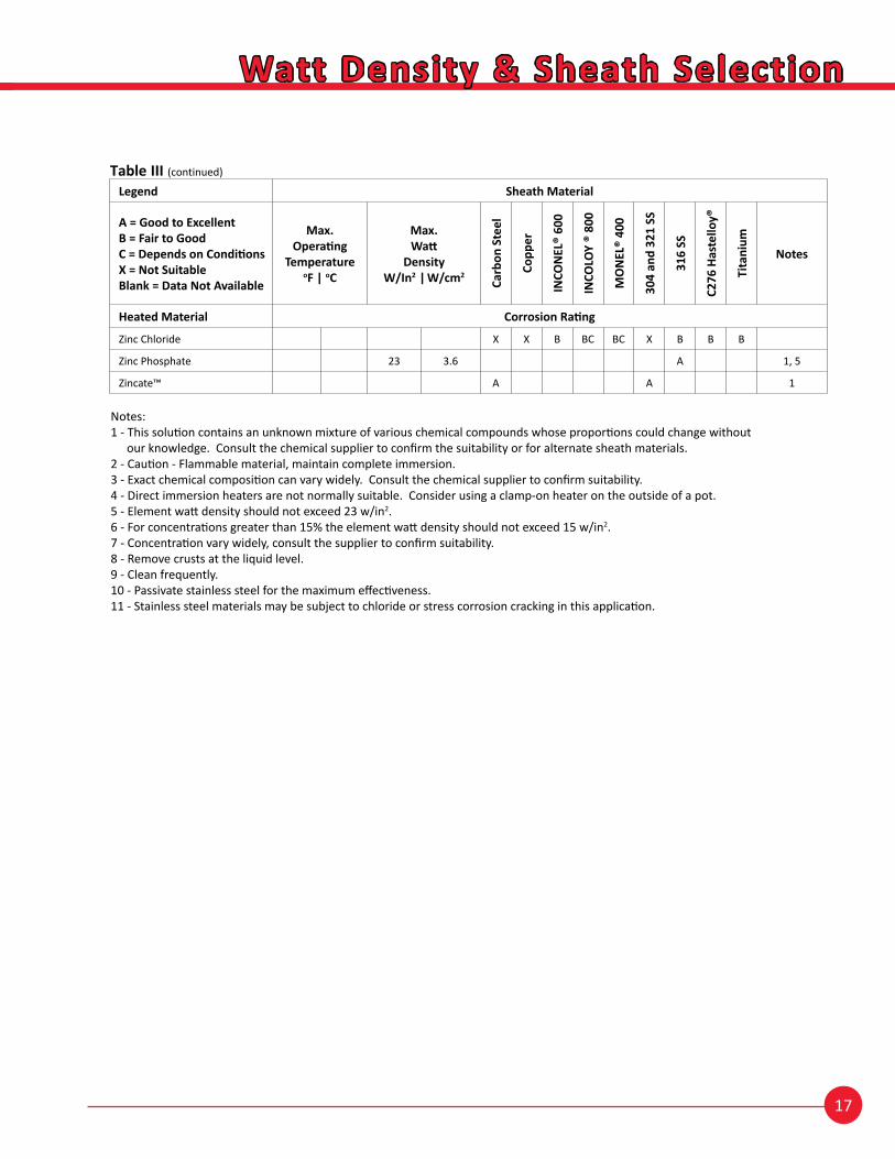
Notes:1 - This solution contains an unknown mixture of various chemical compounds whose proportions could change without
our knowledge. Consult the chemical supplier to confirm the suitability or for alternate sheath materials.2 - Caution - Flammable material, maintain complete immersion.3 - Exact chemical composition can vary widely. Consult the chemical supplier to confirm suitability.4 - Direct immersion heaters are not normally suitable. Consider using a clamp-on heater on the outside of a pot.5 - Element watt density should not exceed 23 w/in2.6 - For concentrations greater than 15% the element watt density should not exceed 15 w/in2.7 - Concentration vary widely, consult the supplier to confirm suitability.8 - Remove crusts at the liquid level.9 - Clean frequently.10 - Passivate stainless steel for the maximum effectiveness.11 - Stainless steel materials may be subject to chloride or stress corrosion cracking in this application.
Legend Sheath Material
A = Good to ExcellentB = Fair to GoodC = Depends on ConditionsX = Not SuitableBlank = Data Not Available
Max.Operating
TemperatureoF | oC
Max.Watt
DensityW/In2 | W/cm2
Carb
on S
teel
Copp
er
INCO
NEL
® 60
0
INCO
LOY
® 80
0
MO
NEL
® 40
0
304
and
321
SS
316
SS
C276
Has
tello
y®
Tita
nium
Notes
Heated Material Corrosion Rating
Zinc Chloride X X B BC BC X B B B
Zinc Phosphate 23 3.6 A 1, 5
Zincate™ A A 1
18
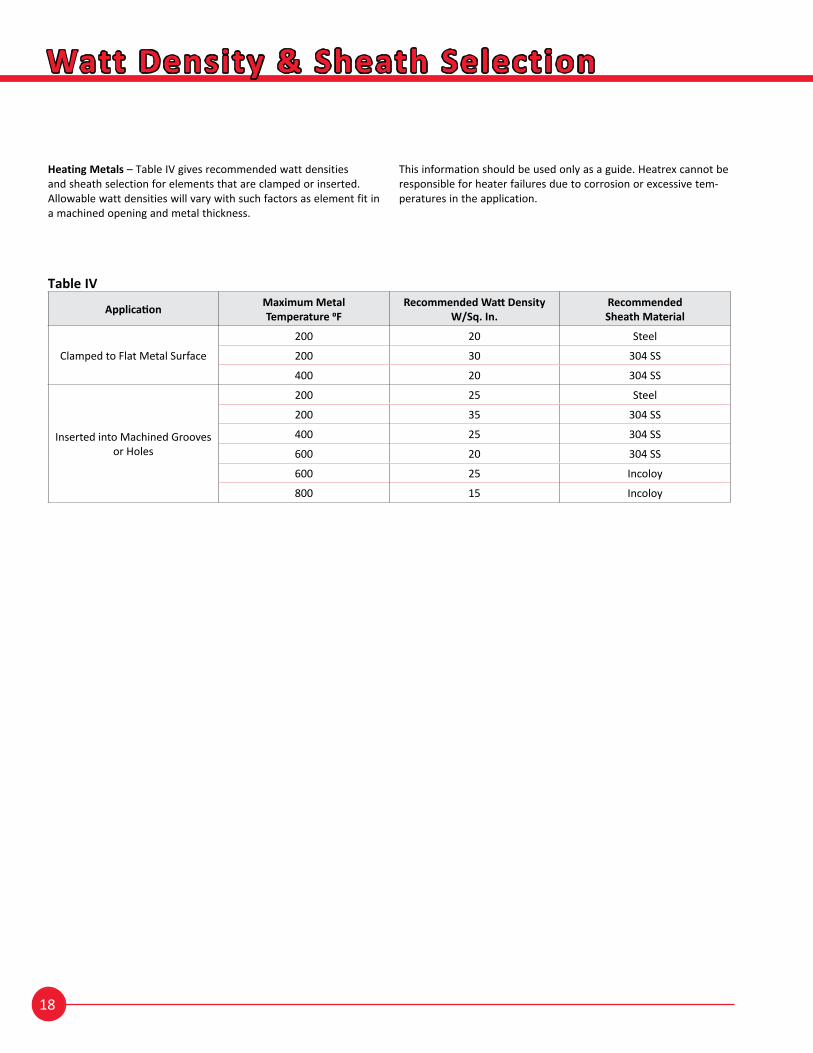
Table IV
Application Maximum MetalTemperature 0F
Recommended Watt DensityW/Sq. In.
Recommended Sheath Material
Clamped to Flat Metal Surface
200 20 Steel
200 30 304 SS
400 20 304 SS
Inserted into Machined Groovesor Holes
200 25 Steel
200 35 304 SS
400 25 304 SS
600 20 304 SS
600 25 Incoloy
800 15 Incoloy
Watt Density & Sheath Selection
Heating Metals – Table IV gives recommended watt densities and sheath selection for elements that are clamped or inserted. Allowable watt densities will vary with such factors as element fit in a machined opening and metal thickness.
This information should be used only as a guide. Heatrex cannot be responsible for heater failures due to corrosion or excessive tem-peratures in the application.