Tennessee Valley Authority, 1101 Market Street, Chattanooga, Tennessee 37402 CNL-17-071 June 30, 2017 10 CFR 50.4 10 CFR 50.54(f) ATTN: Document Control Desk U.S. Nuclear Regulatory Commission Washington, D.C. 20555-0001 Watts Bar Nuclear Plant, Units 1 and 2 Facility Operating License Nos. NPF-90 and NPF-96 NRC Docket Nos. 50-390 and 50-391 Subject: Seismic Probabilistic Risk Assessment for Watts Bar Nuclear Plant, Units 1 and 2 - Response to NRC Request for Information Pursuant to Title 10 of the Code of Federal Regulations 50.54(f) Regarding Recommendation 2.1 of the Near-Term Task Force Review of Insights from the Fukushima Dai-ichi Accident References: 1. NRC Letter, “Request for Information Pursuant to Title 10 of the Code of Federal Regulations 50.54(f) Regarding Recommendations 2.1, 2.3, and 9.3, of the Near-Term Task Force Review of Insights from the Fukushima Dai-ichi Accident,” dated March 12, 2012 (ML12053A340) 2. EPRI Report 1025287, “Seismic Evaluation Guidance, Screening, Prioritization and Implementation Details [SPID] for the Resolution of Fukushima Near-Term Task Force Recommendation 2.1: Seismic,” dated February 2013 (ML12333A170) 3. TVA letter to NRC, “Tennessee Valley Authority’s Seismic Hazard and Screening Report (CEUS Sites), Response to NRC Request for Information Pursuant to 10 CFR 50.54(f) Regarding Recommendation 2.1 of the Near-Term Task Force Review of Insights from the Fukushima Dai-ichi Accident,” dated March 31, 2014 (ML14098A478) 4. NRC letter to TVA, “Watts Bar Nuclear Plant, Unit 1 - Staff Assessment of Information provided Pursuant to Title 10 of the Code of Federal Regulations, Section 50.54(f), Seismic Hazard Reevaluations Relating to Recommendation 2.1 of the Near-Term Task Force Review of Insights from the Fukushima DAI-ICHI Accident (TAC No. MF3769),” dated October 5, 2015 (ML15055A543) L44 170630 003
Transcript
Tennessee Valley Authority, 1101 Market Street, Chattanooga, Tennessee 37402
CNL-17-071
June 30, 2017 10 CFR 50.4
10 CFR 50.54(f)
ATTN: Document Control Desk U.S. Nuclear Regulatory Commission Washington, D.C. 20555-0001
Watts Bar Nuclear Plant, Units 1 and 2 Facility Operating License Nos. NPF-90 and NPF-96 NRC Docket Nos. 50-390 and 50-391
Subject: Seismic Probabilistic Risk Assessment for Watts Bar Nuclear Plant, Units 1 and 2 - Response to NRC Request for Information Pursuant to Title 10 of the Code of Federal Regulations 50.54(f) Regarding Recommendation 2.1 of the Near-Term Task Force Review of Insights from the Fukushima Dai-ichi Accident
References: 1. NRC Letter, “Request for Information Pursuant to Title 10 of the Code of Federal Regulations 50.54(f) Regarding Recommendations 2.1, 2.3, and 9.3, of the Near-Term Task Force Review of Insights from the Fukushima Dai-ichi Accident,” dated March 12, 2012 (ML12053A340)
2. EPRI Report 1025287, “Seismic Evaluation Guidance, Screening,Prioritization and Implementation Details [SPID] for the Resolution ofFukushima Near-Term Task Force Recommendation 2.1: Seismic,” datedFebruary 2013 (ML12333A170)
3. TVA letter to NRC, “Tennessee Valley Authority’s Seismic Hazard andScreening Report (CEUS Sites), Response to NRC Request forInformation Pursuant to 10 CFR 50.54(f) Regarding Recommendation 2.1of the Near-Term Task Force Review of Insights from the FukushimaDai-ichi Accident,” dated March 31, 2014 (ML14098A478)
4. NRC letter to TVA, “Watts Bar Nuclear Plant, Unit 1 - Staff Assessment ofInformation provided Pursuant to Title 10 of the Code of FederalRegulations, Section 50.54(f), Seismic Hazard Reevaluations Relating toRecommendation 2.1 of the Near-Term Task Force Review of Insightsfrom the Fukushima DAI-ICHI Accident (TAC No. MF3769),” datedOctober 5, 2015 (ML15055A543)
L44 170630 003
U.S. Nuclear Regulatory Commission CNL-17-071 Page 2 June 30, 2017 5. NRC letter to TVA, “Watts Bar Nuclear Plant, Unit 2 - Staff Assessment of
Information provided Pursuant to Title 10 of the Code of Federal Regulations, Section 50.54(f), Seismic Hazard Reevaluations Relating to Recommendation 2.1 of the Near-Term Task Force Review of Insights from the Fukushima DAI-ICHI Accident (TAC No. MF3946),” dated October 5, 2015 (ML15111A377)
6. NRC Letter, “Final Determination of Licensee Seismic Probabilistic Risk
Assessments Under the Request for Information Pursuant to Title 10 of the Code of Federal Regulations 50.54(f) Regarding Recommendation 2.1 “Seismic” of the Near-Term Task Force Review of Insights from the Fukushima Dai-ichi Accident,” dated October 27, 2015 (ML15194A015)
On March 12, 2012, the Nuclear Regulatory Commission (NRC) issued a Request for Information pursuant to Title 10 of the Code of Federal Regulations (CFR) Part 50.54(f) (Reference 1) to all power reactor licensees. Enclosure 1 of the 50.54(f) letter requested addressees to reevaluate the seismic hazards at their respective sites using present-day NRC requirements and guidance, and to identify any actions taken or planned to address plant-specific vulnerabilities associated with the updated seismic hazards.
EPRI Report 1025287 (Reference 2) provides the guidance for screening, prioritization, and implementation details for the resolution of the Fukushima Near-Term Task Force (NTTF) Recommendation 2.1: Seismic. The EPRI Screening, Prioritization and Implementation Details (SPID) guidance was used to compare the reevaluated seismic hazard to the design basis seismic hazard for Watts Bar, Units 1 and 2. As described in Reference 3, Enclosure 4, it was concluded that the reevaluated ground motion response spectrum (GMRS) exceeded the design basis response spectrum in the 1 to 10 Hz range. Accordingly, a seismic probabilistic risk assessment was required.
References 4 and 5 are the NRC Staff Assessments for Watts Bar, Units 1 and 2, respectively, seismic hazard submittals which concluded that the reevaluated seismic hazards described in Reference 3, Enclosure 4, are suitable for other activities associated with NTTF Recommendation 2.1: Seismic.
In Reference 6, NRC indicated that a seismic probabilistic risk assessment was required for Watts Bar, Units 1 and 2, and should be submitted to NRC by June 30, 2017.
The Enclosure to this letter provides the Seismic Probabilistic Risk Assessment Summary Report for Watts Bar Nuclear Plant, Units 1 and 2, as requested in Reference 6. The Enclosure provides the information requested in Item (8)B of the 50.54(f) letter associated with NTTF Recommendation 2.1: Seismic.
U.S. Nuclear Regulatory Commission CNL-17-071 Page 3 June 30, 2017
A probabilistic seismic hazard analysis was in progress to support the licensing efforts of Watts Bar, Unit 2, before the 50.54(f) request for information (Reference 1) was issued. This seismic hazard analysis was used for the Watts Bar seismic probabilistic risk assessment in lieu of the NTTF 2.1 submittal (Reference 3, Enclosure 4) since the analysis developed the additional elements required for the seismic probabilistic risk assessment such as Foundation Input Response Spectra, Hazard-Consistent Strain-Compatible Properties, and vertical ground motions. The seismic hazard used in the Watts Bar seismic probabilistic risk assessment envelopes the seismic hazard previously submitted in Reference 3, Enclosure 4.
This letter contains no new regulatory commitments.
If you have any questions regarding this submittal, please contact Russell Thompson at (423) 751-2567.
I declare under penalty of perjury that the foregoing is true and correct. Executed on the 30th day of June 2017.
Respectfully,
J. W . Shea Vice President, Nuclear Regulatory Affairs & Support Services
Enclosure:
Watts Bar Nuclear Plant, Units 1 and 2, Seismic Probabilistic Risk Assessment in Response to 50.54(f) Letter with Regard to NTTF 2.1 Seismic Summary Report
cc (Enclosure):
NRR Director - NRC Headquarters NRO Director - NRC Headquarters NRR JLD Director - NRC Headquarters NRC Regional Administrator - Region II NRC Project Manager - Watts Bar Nuclear Plant NRC Senior Resident Inspector - Watts Bar Nuclear Plant
ENCLOSURE
Watts Bar Nuclear Plant, Units 1 and 2 Seismic Probabilistic Risk Assessment
in Response to 50.54(f) Letter with Regard to NTTF 2.1 Seismic
Summary Report
WATTS BAR NUCLEAR PLANT (WBN) UNITS 1 AND 2 SEISMIC PROBABILISTIC RISK ASSESSMENT IN
RESPONSE TO 50.54(f) LETTER WITH REGARD TO NTTF 2.1 SEISMIC
SUMMARY REPORT
June 2017
WBN 50.54(f) NTTF 2.1 Seismic PRA Summary Report June 2017
Appendix A Seismic PRA Technical Adequacy Assessment and Peer Review
WBN 50.54(f) NTTF 2.1 Seismic PRA Summary Report June 2017
Page 4 of 146
EXECUTIVE SUMMARY
In response to the 10 CFR 50.54(f) letter issued by the Nuclear Regulatory Commission (NRC) on March 12, 2012, a Seismic Probabilistic Risk Assessment (PRA) has been developed for Watts Bar Nuclear Plant Units 1 and 2. The Seismic PRA shows that the point estimate seismic Core Damage Frequency (CDF) is 2.6X10⁻⁶per reactor calendar year (rcy) for Unit 1 and is 2.6X10⁻⁶ per rcy for Unit 2 [12]. The seismic Large Early Release Frequency (LERF) is 1.7X10⁻⁶/rcy [12] for both Units. Note that CDF and LERF throughout this document are always referring to seismic CDF and seismic LERF, not CDF and LERF from all haxards. Sensitivity studies were performed to identify critical assumptions, test the sensitivity to quantification parameters and the seismic hazard, and identify potential areas to consider for the reduction of seismic risk. These sensitivity studies demonstrated that the model results were robust to the modeling and assumptions used. No seismic hazard vulnerabilities were identified, and no plant actions have been taken or are planned given the insights from the seismic risk assessment.
WBN 50.54(f) NTTF 2.1 Seismic PRA Summary Report June 2017
Page 5 of 146
1.0 Purpose and Objective
Following the accident at the Fukushima Dai-ichi nuclear power plant resulting from the March 11, 2011, Great Tohoku Earthquake and subsequent tsunami, the NRC established a Near Term Task Force (NTTF) to conduct a systematic review of NRC processes and regulations and to determine if the agency should make additional improvements to its regulatory system. The NTTF developed a set of recommendations intended to clarify and strengthen the regulatory framework for protection against natural phenomena. Subsequently, the NRC issued a 50.54(f) letter on March 12, 2012 [1], requesting information to assure that these recommendations are addressed by all U.S. nuclear power plants. The 50.54(f) letter requests that licensees and holders of construction permits under 10 CFR Part 50 reevaluate the seismic hazards at their sites against present-day NRC requirements and guidance.
A comparison between the reevaluated seismic hazard and the design basis for Watts Bar Nuclear plant (WBN) Units 1 & 2 has been performed, in accordance with the guidance in Electric Power Research Institute (EPRI) 1025287, “Screening, Prioritization and Implementation Details (SPID) for the Resolution of Fukushima Near-Term Task Force Recommendation 2.1: Seismic” [2], and previously submitted to NRC [3]. That comparison concluded that the Ground Motion Response Spectra (GMRS), which was developed based on the reevaluated seismic hazard, exceeds the design basis seismic response spectrum in the 1 to 10 Hz range, and a seismic risk assessment is required. A seismic PRA has been developed to perform the seismic risk assessment for WBN in response to the 50.54(f) letter, specifically item (8) in Enclosure 1 of the 50.54(f) letter.
This report describes the seismic PRA developed for WBN and provides the information requested in item (8)(B) of Enclosure 1 of the 50.54(f) letter and in Section 6.8 of the SPID. The intent of the Seismic PRA is to assess the seismic risk for WBN, identify which structures, systems, and components (SSCs) are important to seismic risk, and describe plant-specific seismic issues and associated actions planned or taken.
This report provides summary information regarding the Seismic PRA as outlined in Section 2.
The level of detail provided in the report is intended to enable the NRC to understand the inputs and methods used, the evaluations performed, and the decisions made as a result of the insights gained from the WBN seismic PRA.
WBN 50.54(f) NTTF 2.1 Seismic PRA Summary Report June 2017
Page 6 of 146
2.0 Information Provided in This Report
The following information is requested in the 50.54(f) letter [1], Enclosure 1, “Requested Information” Section, paragraph (8)B, for plants performing a Seismic PRA.
(1) The list of the significant contributors to CDF for each seismic acceleration bin, including importance measures (e.g., Risk Achievement Worth, Fussel-Vesely and Birnbaum)
(2) A summary of the methodologies used to estimate the CDF and LERF, including the following:
i. Methodologies used to quantify the seismic fragilities of SSCs, together with key assumptions
ii. SSC fragility values with reference to the method of seismic qualification, the dominant failure mode(s), and the source of information
iii. Seismic fragility parameters iv. Important findings from plant walkdowns and any corrective actions taken v. Process used in the seismic plant response analysis and quantification,
including the specific adaptations made in the internal events PRA model to produce the seismic PRA model and their motivation
vi. Assumptions about containment performance (3) Description of the process used to ensure that the Seismic PRA is technically adequate,
including the dates and findings of any peer reviews (4) Identified plant-specific vulnerabilities and actions that are planned or taken
Note that 50.54(f) letter Enclosure 1 paragraphs 1 through 6, regarding the seismic hazard evaluation reporting, also apply, but have been satisfied through the previously submitted WBN Seismic Hazard Submittal [3][17][18]. Further, 50.54(f) letter Enclosure 1 paragraph 9 requesting information on the Spent Fuel Pool has been satisfied [15] [16].
Table 2.0-1 provides a cross-reference between the 50.54(f) reporting items noted above and the location in this report where the corresponding information is discussed.
The SPID [2] defines the principal parts of a Seismic PRA, and the WBN Seismic PRA has been developed and documented in accordance with the SPID. The main elements of the Seismic PRA performed for WBN in response to the 50.54(f) Seismic letter correspond to those described in Section 6.1.1 of the SPID, i.e.:
Table 2.0-2 provides a cross-reference between the reporting items noted in Section 6.8 of the SPID, other than those already listed in Table 2.0-1, and provides the location in this report where the corresponding information is discussed.
The WBN Seismic PRA and associated documentation has been peer reviewed against the PRA Standard in accordance with the process defined in Nuclear Energy Institute (NEI) 12-13 [5] as documented in the WBN Seismic PRA Peer Review Report. The WBN Seismic PRA, complete Seismic PRA documentation, and details of the peer review are available for NRC review.
WBN 50.54(f) NTTF 2.1 Seismic PRA Summary Report June 2017
Page 7 of 146
Subsequent to the peer review, an independent assessment was performed of the Closure of “Finding” level Facts and Observations of record from the peer review. The assessment was performed via NEI 12-13 Appendix X guidance, which has been accepted by the NRC [33]. The details of the Finding Level F&O independent assessment are available for NRC review.
This submittal provides a summary of the Seismic PRA development, results and insights, the peer review process and results, and the independent assessment, sufficient to meet the 50.54(f) information request in a manner intended to enable NRC to understand and determine the validity of key input data and calculation models used, and to assess the sensitivity of the results to key aspects of the analysis.
The content of this report is organized as follows:
Section 3 provides information related to the WBN seismic hazard analysis.
Section 4 provides information related to the determination of seismic fragilities for WBN SSCs included in the seismic plant response.
Section 5 provides information regarding the plant seismic response model (seismic accident sequence model) and the quantification of results.
Section 6 summarizes the results and conclusions of the Seismic PRA, including identified plant seismic issues and actions taken or planned.
Section 7 provides references.
Section 8 provides a list of acronyms used.
Appendix A provides an assessment of Seismic PRA Technical Adequacy for Response to NTTF 2.1 Seismic 50.54(f) Letter, including a summary of WBN Seismic PRA peer review and independent assessment as well as a discussion of the open findings related to the WBN Internal Events PRA.
WBN 50.54(f) NTTF 2.1 Seismic PRA Summary Report June 2017
Page 8 of 146
Table 2.0-1 Cross-Reference for 50.54(f) Enclosure 1 Seismic PRA Reporting
50.54(f) Letter Reporting Item
Description
Location in this Report
1 List of the significant contributors to CDF for each seismic acceleration bin, including importance measures
The significant contributors are provided in Section 5
2 Summary of the methodologies used to estimate the CDF and LERF
A summary of the methodologies utilized to estimate CDF and LERF are provided in Sections 3, 4, 5
2i Methodologies used to quantify the seismic fragilities of SSCs, together with key assumptions
Seismic methodologies are provided in Section 4
2ii SSC fragility values with reference to the method of seismic qualification, the dominant failure mode(s), and the source of information
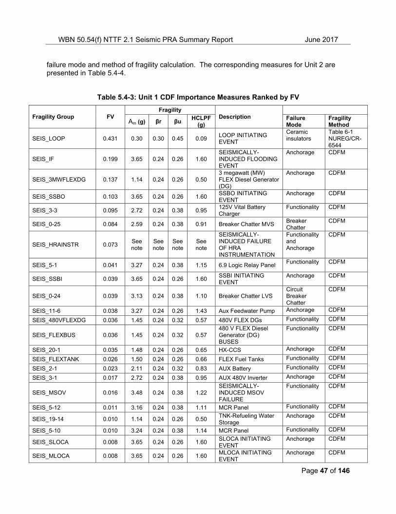
Tables 5.4-3, 5.4-4, 5.5-3, and 5.5-4 provides fragilities (Am, median acceleration capacity, and beta, uncertainty in capacity), failure mode information, and method of determining fragilities for the top risk significant SSCs based on Fussel-Vesely (F-V) [12] [25].
2iii Seismic fragility parameters Tables 5.4-3, 5.4-4, 5.5-3, and 5.5-4 provides fragilities (Am and beta), failure mode information, and method of determining fragilities for the top risk significant SSCs based on Fussel-Vesely (F-V) [12] [25].
2iv Important findings from plant walkdowns and any corrective actions taken
Section 4.2 addresses walkdowns and walkdown insights
2v Process used in the seismic plant response analysis and quantification, including specific adaptations made in the internal events PRA model to produce the seismic PRA model and their motivation
Sections 5.1 provides the processes used in the seismic plant response
2vi Assumptions about containment performance
Sections 4.3 and 5.5 address containment and related SSC performance
3 Description of the process used to ensure that the Seismic PRA is technically adequate, including the dates and findings of any peer reviews
Appendix A describes the assessment of Seismic PRA technical adequacy for the 50.54(f) submittal and results of the Seismic PRA peer review and subsequent independent assessment
4 Identified plant-specific vulnerabilities and actions that are planned or taken
Section 6 addresses the plant-specific vulnerabilities. No vulnerabilities were identified or actions planned as a result of the Seismic PRA.
WBN 50.54(f) NTTF 2.1 Seismic PRA Summary Report June 2017
Page 9 of 146
Table 2.0-2 Cross-Reference for Additional SPID Section 6.8 Seismic PRA Reporting
SPID Section 6.8 Item (1) Description
Location in this Report
A report should be submitted to the NRC summarizing the Seismic PRA inputs, methods, and results.
Entirety of the submittal addresses this.
The level of detail needed in the submittal should be sufficient to enable NRC to understand and determine the validity of all input data and calculation models used
Entirety of the submittal addresses this. The template identifies key methods of analysis and referenced codes and standards
The level of detail needed in the submittal should be sufficient to assess the sensitivity of the results to all key aspects of the analysis
Entirety of the submittal addresses this. Results sensitivities are discussed in the following Section 5.7 (Seismic PRA Quantification Sensitivity Analysis)
The level of detail needed in the submittal should be sufficient to make necessary regulatory decisions as a part of NTTF Phase 2 activities.
Entirety of the submittal template addresses this.
It is not necessary to submit all of the Seismic PRA documentation for such an NRC review. Relevant documentation should be cited in the submittal, and be available for NRC review in easily retrievable form.
Entire report addresses this. This report summarizes important information from the Seismic PRA, with detailed information in lower tier documentation
Documentation criteria for a Seismic PRA are identified throughout the ASME/ANS (American Society of Mechanical Engineers/American Nuclear Society) Standard [4]. Utilities are expected to retain that documentation consistent with the Standard.
This is an expectation relative to documentation of the Seismic PRA that the utility retains to support application of the Seismic PRA to risk-informed plant decision-making.
Note (1): The items listed here do not include those designated in SPID Section 6.8 as “guidance”.
WBN 50.54(f) NTTF 2.1 Seismic PRA Summary Report June 2017
Page 10 of 146
3.0 WBN Seismic Hazard and Plant Response
This section provides summary site information and pertinent features including location and site characterization. The subsections provide brief summaries of the site hazard and plant response characterization.
WBN is a dual unit Westinghouse 4-loop pressurized water reactor located in southeastern Tennessee on the west shore of Chickamauga Lake approximately 50 miles northeast of Chattanooga. The regional and site (local) geology is described in additional detail in the WBN NTTF 2.1 Seismic Hazard submittal [3]. WBN is a firm rock site. The foundation material and foundation elevation for the Category I plant structures is described in Table 3.0-1. The geotechnical profiles are developed using original WBN Units 1 and 2 borehole data supplemented with recent Spectral Analysis of Surface Wave testing at the site.
Table 3.0-1: Category I Structures and Geotechnical Foundation Material
Category I Structure Geotechnical. Foundation Material
Applicable Elevation
Intake Pumping Station Shale/Limestone bedrock 648 ft
Reactor Building, Unit 1 and Unit 2 Shale/Limestone bedrock 664 ft
Auxiliary Building Shale/Limestone bedrock 684 ft
Control Building Shale/Limestone bedrock 684 ft
Diesel Generator Building Crushed Rock 728 ft
Refueling Water Storage Tank, Unit 1 and Unit 2
Granular Backfill 728 ft
3.1 Seismic Hazard Analysis
This section discusses the seismic hazard methodology, presents the final seismic hazard results used in the Seismic PRA, and discusses important assumptions and important sources of uncertainty.
The seismic hazard analysis determines the annual frequency of exceedance for selected ground motion parameters. The analysis involves use of earthquake source models, ground motion attenuation models, characterization of the site response (e.g. soil column), and accounts for the uncertainties and randomness of these parameters to arrive at the site seismic hazard. Detailed information regarding the WBN site hazard was provided to NRC in the seismic hazard information submitted to NRC in response to the NTTF 2.1 Seismic information request [3]. As further discussed below, a supplemental seismic hazard analysis has been performed for WBN [19].
WBN 50.54(f) NTTF 2.1 Seismic PRA Summary Report June 2017
Page 11 of 146
3.2 Seismic Hazard Analysis Methodology
Prior to the NTTF 2.1 activities, a probabilistic seismic hazard analysis was initiated to support potential licensing efforts for WBN Unit 2. This analysis [19] was used for the WBN Seismic PRA in lieu of the NTTF 2.1 submittal [3] since the site analysis develops the additional elements required for the Seismic PRA such as Foundation Input Response Spectra (FIRS), hazard-consistent strain-compatible properties, and vertical ground motions.
To perform the site response analyses for WBN, a random vibration theory approach was employed. This process is consistent with existing NRC guidance and the SPID [2]. The guidance contained in Appendix B of the SPID on incorporating epistemic uncertainty in shear-wave velocities, kappa, non-linear dynamic properties and source spectra was followed for WBN. The GMRS at WBN is defined at the Reactor Building foundation control point at a depth of 64 ft. below plant grade of 728 ft which corresponds to elevation 664 ft mean sea level. FIRS were developed for additional structures at the elevations shown in Table 3.0-1.
The shear wave velocity profiles were very similar to the NTTF 2.1 Seismic Hazard submittal shear wave velocity profiles. Two best case estimate profiles were used to accommodate the dipping nature of the strata beneath the site as shown in Figures 3.2-1 and 3.2-2 for the Reactor Building. In a similar fashion, velocity profiles were developed for the Auxiliary and Control Buildings and the Intake Pumping Station. The depth to the top of the profiles used in the computation of the FIRS for the Auxiliary and Control Building is at a depth of 44 ft below the surface. The top of the profiles for the Intake Pumping Station is at 648 ft at the top of the shale and limestone. The Refueling Water Storage Tank FIRS were computed at an elevation of 728 ft. The top 15 ft is granular backfill with estimated Shear Wave Velocity (Vs) of 1859 ft/sec, which sits atop 15 ft of in situ gravel with Vs of 1500 ft/sec.
WBN 50.54(f) NTTF 2.1 Seismic PRA Summary Report June 2017
Page 12 of 146
Figure 3.2-1: Reactor Building VS Profile A
WBN 50.54(f) NTTF 2.1 Seismic PRA Summary Report June 2017
Page 13 of 146
Figure 3.2-2: Reactor Building VS Profile B
To accommodate the full range in expected dynamic material behavior for the firm rock profiles, linear analyses, as well as nonlinear analyses, were included in the site response analyses, with equal weights given to each approach. This approach was consistent with the approach of the NTTF 2.1 Seismic Hazard submittal. Nonlinear and linear curves were considered in the analysis for the structures founded on soils as well, with equal weights assigned.
For the Reactor Building, adjusted kappa values and weights were equivalent to values and weights in the NTTF 2.1 Seismic Hazard submittal. For the other structures, differences in the kappa estimates from those as the Reactor Building are quite small (<5%) and not significant in
WBN 50.54(f) NTTF 2.1 Seismic PRA Summary Report June 2017
Page 14 of 146
the estimates of amplification. For vertical ground motion analyses, kappa values were taken at one half the values of the horizontal ground motion analyses.
The results of the site response analyses consist of amplification factors which describe the amplification (or de-amplification) of hard reference rock motion as a function of frequency and input reference rock amplitude. The amplification factors are represented in terms of a median amplification value and an associated standard deviation (sigma) for each oscillator frequency and input rock amplitude. Consistent with the SPID [2], a minimum median amplification value of 0.5 was employed in the present analysis. Table 3.2-1 presents the mean and fractile exceedance frequencies for hard rock at 100 Hz. Figures 3.2-3 through 3.2-6 show example median and ± one standard deviation horizontal amplification factors.
The GMRS was developed in accordance with Regulatory Guide 1.208. The SPID states that thirty randomizations are adequate for the site response; therefore thirty were used instead of sixty. In addition to the GMRS, horizontal and vertical FIRS were developed for those structures denoted in Table 3.0-1. The FIRS were developed following the same approach as the development of the GMRS. Site-specific horizontal hazard curves for each of the FIRS site conditions were used.
The reference earthquake ground motion to which the fragilities are referenced is represented by the horizontal ground motion response spectrum (GMRS) also at the Reactor Building (RB) foundation control point. Due to the seismic ruggedness of WBN, a supplemental analysis was performed to a higher reference earthquake for the Diesel Generator Building (DGB). The DGB is founded on backfill while the other structures are founded on rock. The hazard consistent strain compatible properties for the DGB at a reference earthquake of 5.19 x 10⁻⁶ were used for this supplemental analysis.
Peak ground acceleration (PGA) is the ground motion parameter used for the Seismic PRA.
Table 3.2-1 WBN Mean and Fractile Exceedance Frequencies - Hard Rock 100.0 Hz
Exceedance Frequency
PGA (g) 0.15 0.50 Mean 0.85
0.1 1.73E-04 4.18E-04 6.32E-04 1.13E-03
0.15 9.53E-05 2.27E-04 3.43E-04 5.87E-04
0.3 3.1E-05 7.40E-05 1.10E-04 1.83E-04
0.5 1.12E-05 2.80E-05 4.24E-05 7.24E-05
0.70 5.22E-06 1.36E-05 2.10E-05 3.59E-05
1 2.00E-06 5.91E-06 9.30E-06 1.60E-05
1.5 5.72E-07 1.91E-06 3.31E-06 5.63E-06
2 1.96E-07 8.10E-07 1.48E-06 2.57E-06
3 3.98E-08 2.01E-07 4.29E-07 7.53E-07
WBN 50.54(f) NTTF 2.1 Seismic PRA Summary Report June 2017
Page 15 of 146
Figure 3.2-3: Amplification Factors for EPRI Curves M6.5, Single Corner, 0.01 to 0.40 g
WBN 50.54(f) NTTF 2.1 Seismic PRA Summary Report June 2017
Page 16 of 146
Figure 3.2-4: Amplification Factors for EPRI Curves
M6.5, Single Corner, 0501 to 1.50 g
WBN 50.54(f) NTTF 2.1 Seismic PRA Summary Report June 2017
Page 17 of 146
Figure 3.2-5 Amplification Factors for Linear Curves
M6.5, Single Corner, 0.01 to 0.40 g
WBN 50.54(f) NTTF 2.1 Seismic PRA Summary Report June 2017
Page 18 of 146
Figure 3.2-6: Amplification Factors for Linear Curves M6.5, Single Corner, 0.50 to 1.50 g
WBN 50.54(f) NTTF 2.1 Seismic PRA Summary Report June 2017
Page 19 of 146
3.3 Comparison of NTTF 2.1 Seismic Hazard Submittal and PRA Site Analysis
The WBN Seismic PRA used the site response analysis documented in [19]. Table 3.3-1 and Figure 3.3-3 provide the vertical and horizontal GMRS.
Figure 3.3-1 and 3.3-2 compare the NTTF 2.1 Seismic Hazard submittal, assessed by the NRC staff [17] [18], with the Seismic PRA Site Analysis.
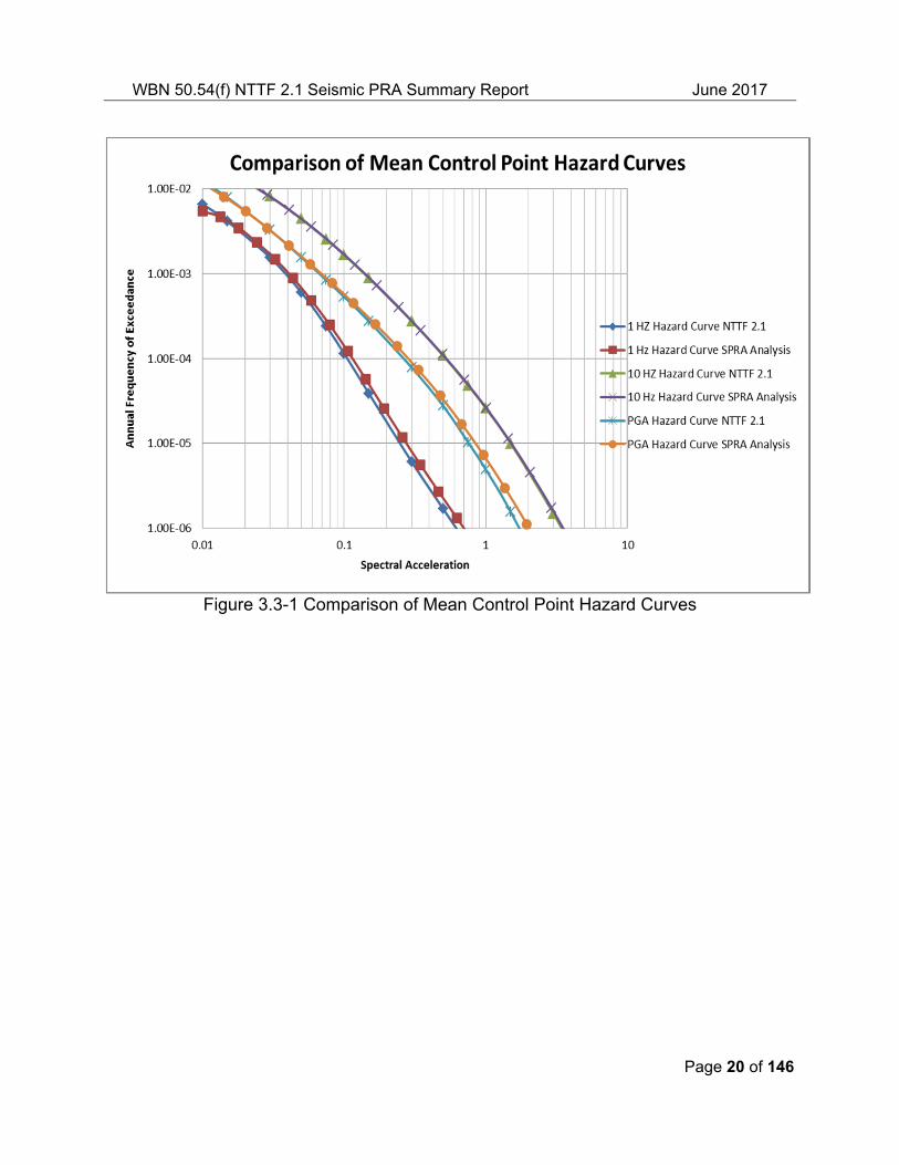
Figure 3.3-1 compares the mean control point hazard curves at frequencies of 1 Hz, 10 Hz and PGA. The figure shows that the hazard curves compare favorably. The figure also shows that for the 1 Hz and PGA curves, above 0.1 g spectral acceleration, the hazard curve used for the Seismic PRA Site Analysis envelope the hazard curve used for NTTF 2.1 Hazard submittal.
Figure 3.3-2 compares the GMRS and shows that the Seismic PRA Site Analysis [19] compares favorably with the NTTF 2.1 Seismic hazard submittal [3]. Below 10 Hz, the figure shows that the Seismic PRA Site Analysis conforms closely to the NTTF 2.1 Information. From 10 Hz to 40 Hz, the figure shows that the Seismic PRA Site Analysis has a slightly higher peak than the NTTF 2.1 Information. Above 40 Hz, the plot shows that the Seismic PRA Site Analysis envelopes the NTTF 2.1 Seismic Hazard submittal.
WBN 50.54(f) NTTF 2.1 Seismic PRA Summary Report June 2017
Page 20 of 146
Figure 3.3-1 Comparison of Mean Control Point Hazard Curves
WBN 50.54(f) NTTF 2.1 Seismic PRA Summary Report June 2017
Page 21 of 146
Figure 3.3-2: Compare NTTF 2.1 Seismic Hazard Submittal and Seismic PRA Seismic Hazard Analysis Horizontal GMRS
3.3.1 Vertical GMRS
The methodology implemented to develop the vertical ground motions follows closely that which was used to develop fully probabilistic site-specific horizontal motions. For application to the development of site-specific vertical hazard, the same fully probabilistic approach was used with Verical/Horizontal (V/H) ratios (median and sigma estimates) substituted for horizontal amplification factors. The development of the V/H ratios is documented in [19]. Table 3.3-1 and Figure 3.3-3 provide the vertical and horizontal GMRS.
3.3.2 Seismic Hazard Analysis Technical Adequacy
The WBN Seismic PRA hazard methodology and analysis was subjected to an independent peer review against the pertinent requirements in the PRA Standard [4]. The Seismic PRA was peer reviewed relative to Capability Category II for the full set of requirements in the Standard. After completion of the subsequent independent assessment, the full set of supporting requirements was met. The seismic hazard analysis was determined to be acceptable for use in the Seismic PRA.
The peer review assessment, and subsequent disposition of peer review findings through an independent assessment, is further described in Appendix A and references [6] and [20].
WBN 50.54(f) NTTF 2.1 Seismic PRA Summary Report June 2017
Page 22 of 146
3.3.3 Seismic Hazard Analysis Results and Insights
Table 3.2-1 provides the final seismic hazard results used as input to the WBN Seismic PRA, in terms of exceedance frequencies as a function of PGA level for the mean and several fractiles at hard rock.
3.3.4 Uncertainties in the seismic hazard result from input parameters and models.
Background sources closer to WBN were found to have a large contribution to the high frequency 10 Hz spectral acceleration hazard. Repeated large magnitude earthquakes (RLME) located much further from WBN contribute to the low frequency 1 Hz spectral acceleration hazard. The most significant RLMEs to WBN are the New Madrid Fault System and Charleston with the New Madrid Fault System being the dominant RLME source. Sensitivities of the hard rock hazard to the ground motion models have been investigated.
Sensitivities of the hard rock hazard to the ground motion models and most significant portions of the seismic source model were performed. The sensitivity analyses indicate a large uncertainty in the rock hazard due to the suite of ground motion models. Also, the sensitivity analyses indicate that the ground motion models for the background seismic source zones and the seismicity rates for the dominant background zone dominate the uncertainty in the PGA.
A review was performed on new information since the earthquake catalog was published in 2012. This review considers post-2012 seismologic, geologic, and geophysical information. Since the WBN Probabilistic Seismic Hazard Analysis (PSHA) was completed in early 2014, additional newer studies for catalog updates at Tennessee Valley Authority (TVA) sites located in close proximity to WBN (less than 40 miles) were used for evaluation of new information. Comprehensive studies for Clinch River site evaluated data up to mid-September 2013 while Sequoyah nuclear site studies considered data up to January 31, 2015. After the review and studies of the new information, it was concluded that the Central and Eastern United States (CEUS) Seismic Source Characterization model did not require an update.
A simplification of the CEUS Seismic Source Characterization model for input into the model software was made for computational efficiency. All background sources were simplified to point sources without fault orientation, dip or width. Justification for this simplification is provided in [32] which illustrated insignificant impact on hazard with an Annual Frequency of Exceedance (AFE) of 10-5 and larger. In addition, for each individual background zone, the average b-value was used instead of individual b-values for each grid cell. A comparison of hazard at the TVA Clinch River site computed using this simplification and without this simplification indicates a difference in hazard of 3% at 10-5.
3.3.5 Horizontal and Vertical GMRS
This section provides the control point horizontal and vertical GMRS.
The GMRS at the control point is plotted in Figure 3.3-3. The development of the control point response spectra is summarized in Section 3.2 and further described in detail in the WBN PSHA report [19].
WBN 50.54(f) NTTF 2.1 Seismic PRA Summary Report June 2017
Page 23 of 146
3.3.5.1 Vertical GMRS
The methodology implemented to develop the vertical ground motions follows closely that used to develop fully probabilistic site-specific horizontal motions. For application to the development of site-specific vertical hazard, the same fully probabilistic approach was used with V/H ratios (median and sigma estimates) substituted for horizontal amplification factors. The development of the V/H ratios is documented in [19].
Table 3.3-1 summarizes the horizontal and vertical response spectra at the control point. Figure 3.3-3 provides a plot of the vertical and horizontal GMRS as well as V/H ratios.
WBN 50.54(f) NTTF 2.1 Seismic PRA Summary Report June 2017
Page 24 of 146
Table 3.3-1 WBN Reactor Building Horizontal and Vertical GMRS and V/H Ratio
WBN 50.54(f) NTTF 2.1 Seismic PRA Summary Report June 2017
Page 25 of 146
Figure 3.3-3 Plot of the Horizontal and Vertical Ground Motions Response Spectra and
V/H Ratios
4.0 Determination of Seismic Fragilities for the Seismic PRA
This section provides a summary of the process for identifying and developing fragilities for SSCs that participate in the plant response to a seismic event for the WBN Seismic PRA. The subsections provide brief summaries of these elements.
4.1 Seismic Equipment List
For the WBN Seismic PRA, a seismic equipment list (SEL) was developed that includes those SSCs that are important to achieving safe shutdown following a seismic event, and to mitigating radioactivity release if core damage occurs, and that are included in the Seismic PRA model. The guidance provided in PRA Standard [4], PRA Procedures Guide [33], EPRI 30020007091 [10] and NTTF 2.3 Walkdown Guidance [34] was used in development of SEL.
The comprehensive SEL was developed by starting with the list of components modeled in the WBN internal events probabilistic risk assessment (IEPRA). That list was then augmented by reviewing equipment contained in the WBN Individual Plant Examination of External Events (IPEEE) safe shutdown equipment lists (SSELs) and the seismic walkdown equipment list. In addition, a separate effort was conducted by the Human Reliability Analysis (HRA) analyst to identify instrumentation needed by operators to support actions modeled in the IEPRA. Components typically not modeled in IEPRAs such as cable trays, conduits, motor control centers, electrical cabinets and panels, Heating, Ventilating, and Air Conditioning (HVAC)
WBN 50.54(f) NTTF 2.1 Seismic PRA Summary Report June 2017
Page 26 of 146
ducting, and piping were identified and included in the SEL. The SEL was also updated after the seismic walkdowns to incorporate additional items such as block walls. The final comprehensive SEL includes any additional SSCs identified after the seismic walkdowns (i.e. relay and breaker chatter events that could not be screened). The SEL includes structures, buildings and substructures, which either contain safety-related equipment or whose failure could impact safety functions or cause a reactor trip. The SEL includes Nuclear Steam Supply System (NSSS) components and components required for containment integrity.
The resulting SEL includes about 2,100 component entries for each unit and about 650 component entries that are shared between the units. The final SEL was documented for the Seismic PRA in [21].
4.1.1 Relay Evaluation
Separate relay chatter studies were performed for each WBN unit to identify relays whose chatter might occur and impact the safety functions of equipment [22] [23]. The studies started with a list of all relays contained in the WBN component database. Those studies identified relays whose contact chatter could not be screened based on evaluation of impact to safety-related equipment in the plant. These relays are listed in Table 4.1-1. These relays were evaluated for contact chatter fragility.
Fragility analysis results for those relays for Units 1 and 2 are summarized the fragility analysis report [25]. The final WBN Seismic PRA model quantification uses a fragility cutoff of Am > 3.5 g. One class of relays had a chatter fragility with Am < 3.5 g (0-22-Relay Chatter-MDR with Am = 3.4 g). However, impacts of chatter for the unscreened relays with Am < 3.5 were reevaluated and determined to impact only main feedwater, which is not credited in the Seismic PRA. Therefore, no relay chatter events were included in the Seismic PRA model.
WBN 50.54(f) NTTF 2.1 Seismic PRA Summary Report June 2017
Page 27 of 146
Table 4.1-1: Summary of Disposition of Unscreened Relays
Relay Function Disposition
1,2-RLY-003-0087/003-A STM GEN No. 3 FW ISOL VLV FCV-3-87-A Am > 3.5g fragility cutoff
1,2-RLY-003-0100/3-B STM GEN No. 4 FW ISOL VLV FCV-3-100-B Am > 3.5g fragility cutoff
1,2-RLY-003-33/3-A STM GEN No. 1 FW ISOL VLV FCV-3-100-B Am > 3.5g fragility cutoff
1,2-RLY-003-47/003-B STM GEN No. 2 FW ISOL VLV FCV-3-47-B Am > 3.5g fragility cutoff
1,2-RLY-003-0148/R3-B SG 3 MTR DRIVEN AUX FW LEVEL CONT Am > 3.5g fragility cutoff
1,2-RLY-003-0156/R3-A SG 2 MTR DRIVEN AUX FW LEVEL CONT Am > 3.5g fragility cutoff
1,2-RLY-003-0164/R3-A SG 1 MTR DRIVEN AUX FW LEVEL CONT Am > 3.5g fragility cutoff
1,2-RLY-003-0171R3-B SG 4 MTR DRIVEN AUX FW LEVEL CONT Am > 3.5g fragility cutoff
1,2-RLY-003-0172/R3-A SG 3 MTR DRIVEN AUX FW LEVEL CONT Am > 3.5g fragility cutoff
1,2-RLY-003-0173/R3-B SG 2 TURB DRIVEN AUX FW LEVEL CONT Am > 3.5g fragility cutoff
1,2-RLY-003-0174/R3-B SG 1 TURB DRIVEN AUX FW LEVEL CONT Am > 3.5g fragility cutoff
1,2-RLY-003-0175/R3-A SG 4 MTR DRIVEN AUX FW LEVEL CONT Am > 3.5g fragility cutoff
1,2-RLY-003-SG1AR-A SG 1 FLOW CONTROL BYPASS & ISOL VLV Am > 3.5g fragility cutoff
1,2-RLY-003-SG1BR-B SG 1 FLOW CONTROL BYPASS & ISOL VLV Am > 3.5g fragility cutoff
1,2-RLY-003-SG2AR-A SG 2 FLOW CONTROL BYPASS & ISOL VLV Am > 3.5g fragility cutoff
1,2-RLY-003-SG2BR-B SG 2 FLOW CONTROL BYPASS & ISOL VLV Am > 3.5g fragility cutoff
1,2-RLY-003-SG3AR-A SG 3 FLOW CONTROL BYPASS & ISOL VLV Am > 3.5g fragility cutoff
1,2-RLY-003-SG3BR-B SG 3 FLOW CONTROL BYPASS & ISOL VLV Am > 3.5g fragility cutoff
1,2-RLY-003-SG4AR-A SG 4 FLOW CONTROL BYPASS & ISOL VLV Am > 3.5g fragility cutoff
1,2-RLY-003-SG4BR-B SG 4 FLOW CONTROL BYPASS & ISOL VLV Am > 3.5g fragility cutoff
1,2-RLY-003-SGMAR-A FW ISOL RESET impacts only main
WBN 50.54(f) NTTF 2.1 Seismic PRA Summary Report June 2017
Page 28 of 146
Table 4.1-1: Summary of Disposition of Unscreened Relays
Relay Function Disposition
1,2-RLY-003-SGMBR-B FW ISOL RESET feedwater which is not credited in Seismic PRA
1,2-RLY-046-R/A-A AUX FW PMP VLV SEP RLY Am > 3.5g fragility cutoff
1,2-RLY-046-R/B-B AUX FW PMP VLV SEP RLY Am > 3.5g fragility cutoff
1,2-RLY-046-RA1-A TURB/MTR DRIVEN AUX FW PMP VLVS AUX RLY Am > 3.5g fragility cutoff
1,2-RLY-046-RA2-A TURB DRIVEN AUX FW VLV SSEP RLY Am > 3.5g fragility cutoff
1,2-RLY-046-RAS-S AFPT PMP MTR DR VLV Am > 3.5g fragility cutoff
1,2-RLY-046-RB1-B TURB/MTR AUX FW PMP VLVS AUX RLY Am > 3.5g fragility cutoff
1,2-RLY-046-RB2-B TURB DRIVEN AUX FW PMP VLV SEP RLY Am > 3.5g fragility cutoff
1,2-RLY-046-RBS-S AFPT PMP MTR DR VLV Am > 3.5g fragility cutoff
4.1.2 Circuit Breaker Evaluation
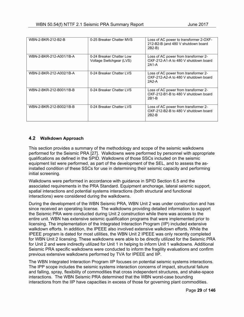
The Unit 2 circuit breaker contact chatter events with Am < 3.5 g are listed in Table 4.1-2. The impacts of the low-voltage circuit breaker chatter events were implemented in the Seismic PRA model by including the four breakers connecting the step down transformers to the 480 Volts (V) shutdown boards. With complete seismic correlation of these breakers, all AC power to these boards is lost. Similarly, impacts of the medium-voltage circuit breaker chatter events were implemented in the Seismic PRA model by including the four breakers connecting the two 6.9 kV shutdown boards to the four step-down transformers feeding the 480V shutdown boards. There are analogous breakers for Unit 1 that are included in the Unit 1 Seismic PRA model.
Table 4.1-2: Circuit Breaker Contact Chatter Events Included in the Seismic PRA Model
Circuit Breaker Fragility Group Chatter Impact
WBN-2-BKR-212-A001/A (also termed A1-A)
0-25 Breaker Chatter Medium Voltage Switchgear (MVS)
Loss of AC power to transformer 2-OXF-212-A1-A (and 480 V shutdown board 2A1-A)
WBN-2-BKR-212-A2-A 0-25 Breaker Chatter MVS Loss of AC power to transformer 2-OXF-212-A2-A (and 480 V shutdown board 2A2-A)
WBN-2-BKR-212-B1-B 0-25 Breaker Chatter MVS Loss of ac power to transformer 2-OXF-212-B1-B (and 480 V shutdown board 2B1-B)
WBN 50.54(f) NTTF 2.1 Seismic PRA Summary Report June 2017
Page 29 of 146
WBN-2-BKR-212-B2-B 0-25 Breaker Chatter MVS Loss of AC power to transformer 2-OXF-212-B2-B (and 480 V shutdown board 2B2-B)
WBN-2-BKR-212-A001/1B-A 0-24 Breaker Chatter Low Voltage Switchgear (LVS)
Loss of AC power from transformer 2-OXF-212-A1-A to 480 V shutdown board 2A1-A
WBN-2-BKR-212-A002/1B-A 0-24 Breaker Chatter LVS Loss of AC power from transformer 2-OXF-212-A2-A to 480 V shutdown board 2A2-A
WBN-2-BKR-212-B001/1B-B 0-24 Breaker Chatter LVS Loss of AC power from transformer 2-OXF-212-B1-B to 480 V shutdown board 2B1-B
WBN-2-BKR-212-B002/1B-B 0-24 Breaker Chatter LVS Loss of AC power from transformer 2-OXF-212-B2-B to 480 V shutdown board 2B2-B
4.2 Walkdown Approach
This section provides a summary of the methodology and scope of the seismic walkdowns performed for the Seismic PRA [27]. Walkdowns were performed by personnel with appropriate qualifications as defined in the SPID. Walkdowns of those SSCs included on the seismic equipment list were performed, as part of the development of the SEL, and to assess the as-installed condition of these SSCs for use in determining their seismic capacity and performing initial screening.
Walkdowns were performed in accordance with guidance in SPID Section 6.5 and the associated requirements in the PRA Standard. Equipment anchorage, lateral seismic support, spatial interactions and potential systems interactions (both structural and functional interactions) were considered during the walkdowns.
During the development of the WBN Seismic PRA, WBN Unit 2 was under construction and has since received an operating license. The walkdowns providing detailed information to support the Seismic PRA were conducted during Unit 2 construction while there was access to the entire unit. WBN has extensive seismic qualification programs that were implemented prior to licensing. The implementation of the Integrated Interaction Program (IIP) included extensive walkdown efforts. In addition, the IPEEE also involved extensive walkdown efforts. While the IPEEE program is dated for most utilities, the WBN Unit 2 IPEEE was only recently completed for WBN Unit 2 licensing. These walkdowns were able to be directly utilized for the Seismic PRA for Unit 2 and were indirectly utilized for Unit 1 in helping to inform Unit 1 walkdowns. Additional Seismic PRA specific walkdowns were conducted to inform the fragility evaluations and confirm previous extensive walkdowns performed by TVA for IPEEE and IIP.
The WBN Integrated Interaction Program IIP focuses on potential seismic systems interactions. The IPP scope includes the seismic systems interaction concerns of impact, structural failure and falling, spray, flexibility of commodities that cross independent structures, and shake-space interactions. The WBN Seismic PRA determined that the WBN worst-case bounding interactions from the IIP have capacities in excess of those for governing plant commodities.
WBN 50.54(f) NTTF 2.1 Seismic PRA Summary Report June 2017
Page 30 of 146
The WBN Seismic PRA walkdowns included selected samples of the distribution systems such as piping, cable trays, electrical conduits and HVAC ducting. The walkdown of selected samples of distribution systems served two purposes. First, the walkdowns provided information for evaluation of fragilities for distributed systems. Second, the walkdowns confirmed the IIP conclusions for distributed systems.
No component capacity screening was performed for WBN because the WBN GMRS seismic hazard is considerably higher than the available industry tools for seismic capacity screening. The purpose of the WBN Seismic PRA walkdown was to evaluate as-designed, as-built, and as-operated plant conditions, in order to identify seismic vulnerabilities and to ensure that the seismic fragilities were realistic and plant specific. The walkdown focused on potential functional and structural failure modes, equipment anchorage, support load path, and potential risk significant seismic interactions including proximity impacts, falling hazards, and differential displacements.
4.2.1 Significant Walkdown Results and Insights
Consistent with the guidance from NP 6041-SL [7], no significant findings or adverse conditions were noted during the WBN seismic walkdowns.
Components on the SEL (that were not previously screened) were evaluated for seismic anchorage and interaction effects, effects of component degradation, such as corrosion and concrete cracking, for consideration in the development of SEL fragilities. In addition, walkdowns were performed on operator pathways, and the potential for seismic-induced fire and flooding scenarios was assessed. Potential internal flood scenarios were incorporated into the WBN Seismic PRA model. The walkdown observations were adequate for use in developing the SSC fragilities for the Seismic PRA.
4.2.2 Seismic Equipment List and Seismic Walkdowns Technical Adequacy
The WBN Seismic PRA SEL development [21] and walkdowns [27] were subjected to an independent peer review against the pertinent requirements in the PRA Standard [4]. The SEL development and walkdowns were peer reviewed relative to Capability Category II for the full set of supporting requirements in the Standard. After completion of the subsequent independent assessment, the full set of supporting requirements was met and the SEL and walkdowns were determined to be acceptable for use in the Seismic PRA.
The peer review assessment, and subsequent disposition of peer review findings through an independent assessment, is further described in Appendix A and references [6] and [20].
4.3 Dynamic Analysis of Structures
This section summarizes the dynamic analysis of structures that contain systems and components important to achieving a safe shutdown [26]. A list of structures and description of relevant parameters is provided in Table 4.3-1.
4.3.1 Fixed-base Analysis
North Steam Valve Rooms (NSVRs)
WBN 50.54(f) NTTF 2.1 Seismic PRA Summary Report June 2017
Page 31 of 146
The NSVRs (one NSVR per unit) protect the isolation valves of the main steam lines and the main feed water lines from the effects of tornado’s and earthquakes, as well as provide support for the valves, main steam lines, and main feed water lines that exit from the Shield Building (SB). The NSVRs are relatively small structures located on the north side of the much larger RB U1 and U2. A two-inch expansion joint separates the NSVR from the RB. The total weight of the NSVR is approximately 15,000 kips. In comparison, the total weight of the RB is about 123,000 kips.
Based on the above characteristics, the seismic analysis of the NSVR assumes fixed-base foundation conditions subjected to the seismic motion of the RB at elevations below grade. In other words, the NSVRs are treated much like a piece of equipment mounted on the SB wall.
4.3.2 Soil Structure Interaction Analysis
4.3.2.1 Structures founded on firm rock
Auxiliary-Control Building (ACB), Reactor Building (RB) and Intake Pumping Station (IPS)
The best estimate soil profile is used in the Soil Structure Interaction (SSI) analysis of the ACB, RB, and the IPS. Because these structures are founded on firm rock, with average Vs of about 5,900 ft/s, overlaying hard rock the soil/rock structure interaction effects are expected to be small and to not significantly influence the seismic response of the structures. Therefore, a best estimate soil profile is appropriate for use in the SSI analysis of the ACB, RB, and the IPS. The use of a best estimate soil profile in the SSI analysis is supported by Appendix C of [2] which shows that the fixed-base assumption ignoring SSI may be appropriate for sites with Vs > 5,200 ft/s.
The seismic analysis of the ACB, RB, and IPS account for the effects of SSI on the seismic response of the building structure. The analytical model for the SSI analysis combines the SAP2000 Finite Element Model (FEM) and the analytical representation of the supporting foundation medium. It accounts for the interaction of the foundation mat with the flexibility of the subsurface material, and included both kinematic interaction due to the foundation mat stiffness and inertial interaction due to the structure mass.
The SSI analysis utilizes the System for Analysis for Soil-Structure Interaction (SASSI) program, developed in the 1980s, at the University of California Berkley.
SASSI represents the geotechnical medium by a uniform or horizontally-layered elastic to viscoelastic soil system overlaying a uniform elastic half space. The stiffness and damping characteristics of the soil layers are represented by strain-compatible soil properties presented in “PSHA” without further modification. The program substructures the soil-structure system into;
(1) The free-field soil medium before excavation.
(2) The excavated soil volume to be replaced by the structural element.
(3) The building structure, including its foundation.
It then solves the equations of motion representing the seismic SSI response in the frequency domain at selected analysis frequencies. The resulting transfer functions are then interpolated
WBN 50.54(f) NTTF 2.1 Seismic PRA Summary Report June 2017
Page 32 of 146
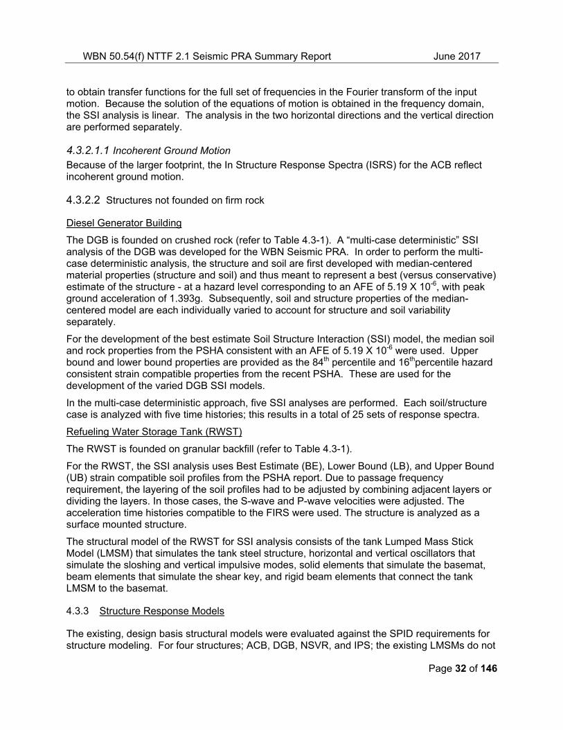
to obtain transfer functions for the full set of frequencies in the Fourier transform of the input motion. Because the solution of the equations of motion is obtained in the frequency domain, the SSI analysis is linear. The analysis in the two horizontal directions and the vertical direction are performed separately.
4.3.2.1.1 Incoherent Ground Motion Because of the larger footprint, the In Structure Response Spectra (ISRS) for the ACB reflect incoherent ground motion.
4.3.2.2 Structures not founded on firm rock
Diesel Generator Building
The DGB is founded on crushed rock (refer to Table 4.3-1). A “multi-case deterministic” SSI analysis of the DGB was developed for the WBN Seismic PRA. In order to perform the multi-case deterministic analysis, the structure and soil are first developed with median-centered material properties (structure and soil) and thus meant to represent a best (versus conservative) estimate of the structure - at a hazard level corresponding to an AFE of 5.19 X 10⁻⁶, with peak ground acceleration of 1.393g. Subsequently, soil and structure properties of the median-centered model are each individually varied to account for structure and soil variability separately.
For the development of the best estimate Soil Structure Interaction (SSI) model, the median soil and rock properties from the PSHA consistent with an AFE of 5.19 X 10⁻⁶ were used. Upper bound and lower bound properties are provided as the 84th percentile and 16thpercentile hazard consistent strain compatible properties from the recent PSHA. These are used for the development of the varied DGB SSI models.
In the multi-case deterministic approach, five SSI analyses are performed. Each soil/structure case is analyzed with five time histories; this results in a total of 25 sets of response spectra.
Refueling Water Storage Tank (RWST)
The RWST is founded on granular backfill (refer to Table 4.3-1).
For the RWST, the SSI analysis uses Best Estimate (BE), Lower Bound (LB), and Upper Bound (UB) strain compatible soil profiles from the PSHA report. Due to passage frequency requirement, the layering of the soil profiles had to be adjusted by combining adjacent layers or dividing the layers. In those cases, the S-wave and P-wave velocities were adjusted. The acceleration time histories compatible to the FIRS were used. The structure is analyzed as a surface mounted structure.
The structural model of the RWST for SSI analysis consists of the tank Lumped Mass Stick Model (LMSM) that simulates the tank steel structure, horizontal and vertical oscillators that simulate the sloshing and vertical impulsive modes, solid elements that simulate the basemat, beam elements that simulate the shear key, and rigid beam elements that connect the tank LMSM to the basemat.
4.3.3 Structure Response Models
The existing, design basis structural models were evaluated against the SPID requirements for structure modeling. For four structures; ACB, DGB, NSVR, and IPS; the existing LMSMs do not
WBN 50.54(f) NTTF 2.1 Seismic PRA Summary Report June 2017
Page 33 of 146
satisfy SPID requirements because of structural asymmetry, floor diaphragm flexibility, effects of concrete cracking and distribution of floor mass that was only approximately represented in the LMSM. For these four structures new 3D finite element models were developed. The new 3D finite element models satisfy SPID requirements for structure modeling and incorporated the geometry, configuration, and dimensions of the structural components of the building such as the foundation and floor slabs, walls and openings
Two structures, RWST and RB, use the LMSM reported in the Final Safety Analysis Report (FSAR). The use of the LMSM for the RWST satisfies SPID requirements because the structure is relatively simple and symmetric. The RB includes three structural systems [SB, Steel Containment Vessel (SCV), and Interior Concrete Structure/ Nuclear Steam Supply System (ICS/NSSS)] supported by a common foundation mat. The SB, SCV, and the ICS/NSSS are represented by LMSMs developed earlier and reported in the FSAR. The use of LMSMs for the SB and SCV is justified on the basis that these structures are relatively simple and symmetric. The LMSM for the ICS is verified and validated by means of independent evaluations using FEMs. The strategy of using the previous LMSM for the RB credits much of the previous extensive modeling effort, particularly the coupling of the NSSS system to the ICS.
4.3.3.1 Structural Damping Values
Although a higher damping value may be justified for some components, a concrete damping of seven percent is used assuming Damage Level 2 [31]. Steel damping is taken to be four per cent. These damping values are somewhat conservatively biased relative to the likely damage state associated with the median seismic capacities for the SSCs.
4.3.3.2 Concrete cracking
Consistent with the expected response levels of the structures at ground levels dominating seismic risk, the effective stiffness of the structure is represented by cracked section properties recommended in [31]. The flexural and shear stiffness values are considered to be 0.5 X gross un-cracked flexural and shear stiffness values. The axial stiffness is maintained at 1.0 X gross un-cracked axial stiffness.
4.3.3.3 ISRS ACB, RB, IPS
The ISRS developed from dynamic analysis are median for the ACB, Reactor Building, and Intake Pumping Station.
ISRS at selected locations are obtained separately due to three directions of input motion (X, Y, and Z). The resulting response spectra are then combined using Square-Root-Sum-of-Squares (SRSS). For example, the three ISRS at a specific location in the NS direction resulting from ground motion input, respectively in the NS, EW, and vertical directions are combined using SRSS.
With the exception of the ACB, the ISRS results are developed considering coherent ground motion. Because of the larger footprint, the ISRS developed for the ACB reflect incoherent ground motion.
4.3.3.4 ISRS DGB
For the DGB, both median and 84th percentile ISRS were developed from the dynamic analysis.
WBN 50.54(f) NTTF 2.1 Seismic PRA Summary Report June 2017
Page 34 of 146
In the multi-case deterministic approach, five SSI analyses are performed. Each soil/structure case is analyzed with five time histories; this results in a total of 25 sets of response spectra. For each analysis case, the outputs obtained from the five time histories are averaged, thus resulting in 5 sets of ISRS. Two sets of ISRS are provided for each area; (1) Median and (2) Conservative (~84thpercentile). These are obtained, respectively, by (1) averaging the five averaged sets of ISRS, and (2) enveloping the five averaged sets of ISRSs, and filling in the valleys.
WBN 50.54(f) NTTF 2.1 Seismic PRA Summary Report June 2017
Page 35 of 146
Table 4.3-1 Description of Structures and Analysis Methods for WBN Seismic PRA
Structure Foundation Condition
Type of Model
Analysis Method Comments/Other Information
Auxiliary Control Building Rock 3D FEM Single time history SSI
Shear Wave velocity average about 5,900 ft/sec.
SSI analysis performed with incoherence
Reactor Building
Rock LMSM Single time history SSI
Shear Wave velocity average about 5,900 ft/sec.
SSI analysis.
ICS model calibrated by FE Model
Intake Pumping Station Rock 3D FEM Single time history SSI
Shear Wave velocity average about 5,900 ft/sec; SSI analysis
Diesel Generator Building
Crushed Rock
3D FEM 5 sets pf spectrally matched time histories SSI
Multi-case deterministic SSI analysis. Developed median and 84% ISRS. 7% damp. Variability of soil and structure properties to generate LB and UB models for both soil and structure
North Steam Valve Room
Crushed Rock / Rock Floor slab on crushed rock fill is supported by vertical walls anchored into rock
3D FEM Single Time History Fixed base. Because of the proximity of the large mass of the RB to the NSVR, the horizontal input motion is taken to be the response time history of the SB at appropriate elevation.
The WBN Seismic PRA Seismic Structure Response and Soil Structure Interaction Analysis [26] were subjected to an independent peer review against the pertinent requirements in the PRA
WBN 50.54(f) NTTF 2.1 Seismic PRA Summary Report June 2017
Page 36 of 146
Standard [4]. The seismic structure response and soil structure interaction was peer reviewed relative to Capability Category II for the full set of requirements in the Standard. After completion of the subsequent independent assessment, the full set of requirements was met and the seismic structure response and soil structure interaction were determined to be acceptable for use in the Seismic PRA.
The peer review assessment, and subsequent disposition of peer review findings through an independent assessment, is further described in Appendix A and references [6] and [20].
4.3.5 SSC Fragility Analysis
The SSC seismic fragility analysis considers the impact of seismic events on the probability of SSC failures at a given value of a seismic motion parameter defined as peak ground acceleration (PGA). The fragilities of the SSCs that participate in the Seismic PRA accident sequences, i.e., those included on the seismic equipment list (SEL) are addressed in the model. Seismic fragilities for the significant risk contributors (i.e., those which have an important contribution to plant risk, are realistic and plant-specific based on actual current conditions of the SSCs in the plant) are confirmed through the detailed walkdown of the plant.
This section summarizes the fragility analysis methodology, presents a tabulation of the fragilities (with appropriate parameters (e.g., Am, βr, βu) and the calculation method and failure modes) for those SSCs determined to be sufficiently risk important, based on the final Seismic PRA quantification (as summarized in Section 5) [25]. Important assumptions and important sources of uncertainty, and any particular fragility-related insights identified, are also discussed.
4.3.6 SSC Screening Approach
4.3.6.1 Rugged Components
Certain components are inherently rugged and consequently have a very low probability of failing as a result of a seismic event. Consistent with long-standing practice in seismic PRAs, seismic failure of such components need not be included in the PRA logic models. Exclusion of such SSCs from the logic models does not affect seismic CDF of LERF or the insights derived from the seismic PRA. Guidance in the SPID and other industry documents was followed for identifying seismically rugged components.
Components considered to be durable or rugged include dampers, filters, check valves, hand operated valves, relief valves, safety heads (rupture disks), and strainers.
4.3.6.2 Piping outside containment connecting to the Reactor Coolant System (RCS)
A review of piping connected to the RCS and extending outside containment was performed to identify lines which if ruptured outside containment and not isolated might contribute significantly to CDF and/or LERF. These piping lines include lines and evaluated for ISLOCA and breaks outside containment in the Internal Events PRA. Frequencies of seismically induced piping rupture and failure of isolation valves were estimated conservatively for the lines. These lines were screened (not included in the Seismic PRA) if the frequency of rupture and failure of isolation valves was less than 1E-9/y. The screening level < 0.1% of both CDF and LERF. The Chemical Volume and Control System letdown line, Residual Heat Removal (RHR) supply line, and seal water and letdown lines did not screen. Therefore, seismically induced ruptures of those lines were included in the Seismic PRA model.
WBN 50.54(f) NTTF 2.1 Seismic PRA Summary Report June 2017
Page 37 of 146
4.3.6.3 Screening Components in Non-Category I Structures
Several components on the SEL are mounted in Non-Category I structures. These structures and components are not credited on the basis that a nominally low bounding fragility shows that these SSCs are not significant contributors to risk. It is assumed in the base case Seismic PRA model that non-safety-related components fail. Sensitivity Case 7 assigned these components a High Confidence of Low Probability of Failure (HCLPF) = 0.4. The change in CDF was ~0.0% and the change in LERF was ~0.1%.
4.3.6.3.1 Reactor Protection System The Reactor Protection System (RPS) is designed to be fail-safe. As such, the system presents a scenario in which component failures generally cause a partial or complete scram signal, rather than prevent a scram signal. Also, the RPS has significant diversity in terms of available scram signals. Therefore, the electrical portion of the RPS is not assigned a fragility.
4.3.6.3.2 Excessive settlement Because all structures at WBN are supported on competent rock or backfill material, excessive settlements and bearing capacity failures are screened out.
4.3.6.3.3 Rule-of-the Box
Except for relays and breakers, components mounted on other components are screened by the rule-of-the-box. Examples include level indicators inside tanks, transmitters mounted on a local instrument rack, and switches mounted on a rack or panel. These components are still addressed in the fragility analysis, but no specific fragility was calculated for them; instead, they are assigned the fragility of the box on which they are mounted.
4.3.7 SSC Fragility Analysis Methodology
Consistent with the requirements in ASME/ANS PRA Standard [4], the fragility analysis for the selected SSCs is based on the methodology in EPRI guidelines. The strategy for developing the fragilities for the complete set of SSCs on the Seismic PRA SEL follows the recommendations of EPRI NP-6041-SL [7], EPRI 1019200 [28], and EPRI 103959 [29] and proceeds progressively from using experienced-based capacities to component-specific-evaluations. Regardless of the method, the development of fragility estimates use plant-specific information based on SSC conditions, as confirmed through detailed walkdowns.
Components are first binned into equipment classes, e.g. EPRI classes presented in Appendix F of EPRI NP 6041-SL [7] and then grouped according to similarity and location. Representative samples in each equipment group are then evaluated to obtain fragility estimates for all the items in the group.
To obtain fragility estimates, the WBN Seismic PRA uses the Conservative Deterministic Failure Margin (CDFM) approach described in EPRI NP-6041-SL [7] and EPRI 1019200[28]. Briefly, the CDFM approach first determines the seismic demand on the plant SSCs due to the GMRS. It then compares this response to the mounting-level failure capacities of SSCs. Failure of a component is defined broadly as loss of component function. Because of the manner in which the demand and capacities are developed the CDFM method results in HCLPF level capacities. The fragility analysis obtains HCLPF capacities of components, and then uses these in
WBN 50.54(f) NTTF 2.1 Seismic PRA Summary Report June 2017
Page 38 of 146
conjunction with randomness and uncertainty variables (βr and βu) to estimate median acceleration capacities (Am).
The Seismic PRA quantification based on the initial set of fragilities identifies the relative importance of items to CDF and LERF and provides the basis to focus on refining fragilities for components that contribute significantly to the CDF and LERF. Following the initial quantification, the fragilities of contributing components are re-evaluated based on plant specific and component-specific information such as test response spectra and qualification analysis, and improved analytical models. Possible conservatisms, either in the fragilities or in the systems analysis, are targeted for improvement.
Critical failure modes were identified, structure/anchorage or functionality or block wall and fragility calculations were performed for the median capacity Am. The lowest, governing Am was selected.
The nuclear steam supply system (NSSS) was evaluated for fragility variables. The NSSS includes the reactor vessel, the steam generators, the reactor coolant pumps, a pressurizer, and the piping that connects these components to the reactor vessel. The fragility evaluation of these components was based on scaling of the existing safety analysis results, in accordance with SPID guidance.
4.3.8 SSC Fragility Analysis Results and Insights
The final set of fragilities for the risk important contributors to CDF and LERF are summarized in Section 5, Tables 5.4-3 and 5.4-4 (for CDF) and Tables 5.5-3 and 5.5-4 (for LERF). Detailed separation of variables (SoV) calculations have been performed for selected high risk significant SSCs and those are denoted in the tables, as applicable.
4.3.9 SSC Fragility Analysis Technical Adequacy
The WBN Seismic PRA SSC Fragility Analysis [25] was subjected to an independent peer review against the pertinent requirements in the PRA Standard [4]. The SSC fragility analysis was peer reviewed relative to Capability Category II for the full set of supporting requirements in the standard. After completion of the subsequent independent assessment [20], the full set of supporting requirements were met and the SSC fragility analysis was determined to be acceptable for use in the Seismic PRA.
The peer review assessment, and subsequent disposition and closure of peer review findings through an independent assessment, is further described in Appendix A and references [6] and [20].
WBN 50.54(f) NTTF 2.1 Seismic PRA Summary Report June 2017
Page 39 of 146
5.0 Plant Seismic Logic Model
The seismic plant response analysis models the various combinations of structural, equipment, and human failures given the occurrence of a seismic event that could initiate and propagate a seismic core damage or large early release sequence. This model is quantified to determine the overall CDF and LERF and to identify the important contributors, e.g., important accident sequences, SSC failures, and human actions. The quantification process also includes an evaluation of sources of uncertainty and provides a perspective on how such sources of uncertainty affect Seismic PRA insights.
5.1 Development of the Seismic PRA Plant Seismic Logic Model
The WBN seismic response model was developed by starting with the WBN internal events at power PRA model of record as of January 2014 , and adapting the model in accordance with guidance in the SPID [2] and PRA Standard [4], including the addition of seismic fragility-related basic events to the appropriate portions of the internal events PRA, eliminating some parts of the internal events model that do not apply or that were screened-out, and adjusting the internal events PRA model human reliability analysis to account for response during and following a seismic event. This modeling approach leaves the IEPRA model logic intact while incorporating the necessary additions required for the Seismic PRA. The model is developed using the EPRI Risk and Reliability Workstation software suite (CAFTA, FRANX, HRA Calculator, and UNCERT). The permanently installed 480V Flexible and Diverse Coping Strategies (FLEX) diesel generators and the 6.9kV FLEX diesel generators are credited in the model. Both random and seismic-induced failures of modeled SSCs are included.
5.1.1 Seismic Initiating Event
The seismic initiating event was modeled using 8 discrete hazard bins based on increasing peak ground acceleration. The seismic hazard bins are listed in Table 5.1-1. Each bin is treated as a seismic initiator and the CDF and LERF results are summed over all the bins to obtain the total CDF and LERF.
The bin ranges were chosen such that the first bin covers the PGA range from the Operating Basis Earthquake (OBE) to the Safe Shutdown Earthquake (SSE), while the second covers the range from the SSE to a common review level earthquake (RLE) of 0.3g.
The OBE, the strongest earthquake at which the plant is designed to be able to continue normal operation, is defined as 0.09g. Below 0.09g, no significant seismic impacts are expected. The safe shutdown earthquake (SSE) is defined as an acceleration of 0.18g. The plant is seismically designed such that safety-related equipment should not fail given an SSE.
WBN 50.54(f) NTTF 2.1 Seismic PRA Summary Report June 2017
The internal events PRA (IEPRA) uses event trees (ETs) to model the potential plant responses to initiating events (IEs). The seismic PRA (Seismic PRA) uses the same approach. The Seismic PRA uses a seismic initiating event tree (SIET) to partition the seismic initiating event into accident sequence types typically modeled in the IEPRA. Transfers can then be made from the SIET to the corresponding IEPRA ETs to model plant response.
The SIET top events include the recommended minimum set of initiating events listed in NUREG/CR-4840 except for the initial status of the power conversion system. No credit is taken for non-safety-related equipment such as the power conversion system in the WBN Seismic PRA base case. A sensitivity analysis indicates essentially no change to CDF or LERF if non-safety-related equipment is credited.
An additional top event involving seismically induced direct core damage is included in the SIET. The sequence leads directly to core damage and therefore does not transfer to an IEPRA ET. Structural failures of the reactor building (RB), auxiliary control building (ACB), or diesel generator building (DGB) combined with a loss of offsite power (LOOP) are assumed to lead directly to core damage. Reactor vessel ruptures or other excessive Loss of Coolant Accidents (LOCA) are also assumed to lead to core damage. Structural support failures of the reactor pressure vessel, pressurizer, or steam generator are assumed to lead directly to core damage. Finally, seismic failure of the control room resulting in operator abandonment and failure to shut down the plant remotely is assumed to lead to core damage.
5.1.3 Loss of Offsite Power
The fragility of seismically induced LOOP resulting from switchyard or grid failures was obtained from Table 6-1 in NUREG/CR-6544 [9]. Seismic-induced LOOP is predicted to occur at 0.3g. The predicted failure mode is failure of ceramic insulators in the switchyard. Use of this fragility for seismically induced LOOP is a standard industry practice for plants in the eastern portion of
WBN 50.54(f) NTTF 2.1 Seismic PRA Summary Report June 2017
Page 41 of 146
the US. The path for transmission of offsite power to safety-related equipment and non-safety-related equipment within the plant was considered to be governed by the fragility for seismically induced offsite power. This includes any paths through the Turbine Building (TB). Note that seismically induced LOOP is assumed to fail both switchyards (complete seismic correlation). The Seismic PRA takes no credit for recovery of offsite power.
5.1.4 Very Small LOCA
Seismic PRAs need to consider whether a coincident very small LOCA needs to be modeled for other SIET sequences. For other LOCA sequences (Small, Medium, Large, and Interfacing System), the addition of a coincident very small LOCA would have no impact because the other LOCA modeled is already larger than a very small LOCA. Also, the direct core damage events modeled are not impacted by a very small LOCA because they are assumed to go directly to core damage and early release. Inclusion of a coincident very small LOCA might potentially impact accident progression and success for SIET sequences of general transient, steam generator tube rupture, secondary side break inside containment, and secondary side break outside containment. However, the fragility analysis determined that the seismic capacity for the very small LOCA was very high (Am=3.65g). A sensitivity study [12] was performed in which all accident sequences originally not leading to core damage or large early release were assigned a very small LOCA initiating event with its associated fragility of 3.65 g. These sequences were assumed to result directly in core damage or large early release. This resulted in very small increases in CDF and LERF. Therefore, not assuming a coincident very small LOCA for four of the SIET sequences is justified.
5.1.5 Median Ground Acceleration (Am)
Often, the large number of component fragilities makes the Seismic PRA model difficult to quantify. This is a software and computer hardware limitation typically encountered when quantifying complex Seismic PRA models. To address the limitation, the final CDF and LERF quantifications did not include component fragilities with Am > 3.5g. The fragility truncation limit was not applied to seismically induced failures modeled in the SIET logic. To evaluate the effect of the fragility truncation limit, a sensitivity study was performed. The sensitivity study was performed by adding a single event to the Seismic PRA as direct core damage event with Am = 3.5 g. The sensitivity analysis indicated that such an event increased CDF by 0.8% and LERF by 1.1%.
Refer to Section 5.7 “Seismic PRA Quantification Sensitivity Analysis” for additional information.
5.1.6 Approach to modeling containment performance
The Seismic PRA considered three seismically induced failure mechanisms that might result in a loss of containment of integrity [2].
The first mechanism involves a gross failure of the containment pressure boundary due to seismic events. Potential failure modes include failure of the basemat in shear and bending, failure of the liner, failure of reinforcing bars, failure of containment walls in transverse shear, and failure due to the interaction of containment and auxiliary structures. These failure modes are assumed to progress directly to core damage, are assigned to a containment bypass accident class, and are assigned to LERF.
WBN 50.54(f) NTTF 2.1 Seismic PRA Summary Report June 2017
Page 42 of 146
The second mechanism involves the failure of the containment to isolate and to maintain isolation following a seismic event. Implied in this failure are the mechanism are the earthquake results in other internal failures that would necessitate automatic containment isolation. Potential failure modes include mechanical failure of isolation valves and control circuity failures affecting isolation valves. These failure types have been addressed by the assignment of fragility identifiers to all components/basic events that can be impacted by a seismic event.
The third mechanism involves the loss of pressure boundary integrity from containment penetrations. Earthquakes of large magnitude could result in the failure of piping bellows or electrical penetrations. The integrity of personnel air locks, equipment hatches, and escape locks could also be affected. Seismically induced loss of pressure boundary of containment penetrations was addressed by a fragility assessment of containment penetrations and the addition representative events within the Level 2 model.
5.1.7 Summary of Resulting Correlated Component Groupings
Correlation of components (or common cause failure) is considered in accordance with the ASME/ANS PRA Standard [4]. There are insufficient data on correlation of seismic failures of similar components in similar locations and alignments to perform sophisticated seismic correlations in Seismic PRAs. Instead, a common practice is to assume complete seismic correlation for these groups of similar components, locations, and alignments.
The base Seismic PRA results involve complete seismic correlation within fragility groups. If all seismically correlated groups are set to uncorrelated, then CDF increases 7.3% and LERF is increased 17.8%. Often CDF and LERF are reduced with this type of sensitivity analysis. However, the WBN Seismic PRA model has sufficient failure events leading directly to CDF and LERF such that un-correlating those groups results in increases rather than decreases.
5.1.8 Summary of HRA methodology
Guidance for this analysis came from the EPRI report “A Preliminary Approach to Human Reliability Analysis for External Events with a Focus on Seismic” [30]. Human Failure Events (HFEs) from the IEPRA were the starting point as documented in the HRA Calculator database. Four sets of human error probabilities (HEPs) were generated for each of the HFEs, based on the damage states defined in the EPRI document.
The IEPRA HRA Calculator database was the starting point for the SHRA task. All HFEs contained in the database were screened for applicability to the Seismic PRA. Non-applicable HFEs were excluded from the SHRA task and applicable HFEs were included in the SHRA task [8].
Development of screening HEPs involved application of multipliers to the IEPRA HEPs to account for additional stress, communication, timing, and access issues resulting from seismic events.
Risk significant HFEs were analyzed with detailed HRA, in accordance with the guidance in EPRI 10025294 [30]. After initial quantification of the WBN Seismic PRA model, HFEs were identified as risk significant. The definition of a risk significant HFE is having a Fussell-Vesely (FV) >= 5E-03 or a Risk Achievement Worth (RAW) >= 2. The EPRI approach for seismic HRA directs the detailed analysis of HFEs to be performed in two parts: qualitative and quantitative analysis. In practice these are done in tandem for each HFE and the starting point for the WBN seismic HRA is the IEPRA HRA. Detailed analysis was performed for EPRI damage states 1
WBN 50.54(f) NTTF 2.1 Seismic PRA Summary Report June 2017
Page 43 of 146
through 3 for the initially risk significant HFEs. No detailed analysis was performed for EPRI damage state 4, as all HEPs in this damage state were set to 1.0 due to the damage state and the uncertainty of instrumentation availability. Where necessary, the seismic HFE analysis was updated to use the most state of the art HRA methods.
Instrumentation, and therefore the cues for operator actions, was assumed to be available for EPRI Bins 1-3, and unavailable for EPRI Bin 4 when determining HEPs. For EPRI Bins 1-3, the seismic impact on instrumentation was accounted for in the fault tree logic by combining the HEPs with the hazard bin specific probability of failure of instrumentation. The probability of instrumentation failure for each hazard bin was obtained by combining the fragilities of the most sensitive critical instrumentation parameter component with the fragility of instrumentation power supply. If instrumentation was not available, then no credit was taken for operator actions. This modeling approach was used for both screening and refined HEPs in the Seismic PRA model.
After initial quantification of the WBN Seismic PRA model, HFEs were identified as risk significant. The definition of a risk significant HFE is having an FV > 5E-03 or RAW > 2. Risk significant HFEs were analyzed with detailed HRA, in accordance with the guidance in EPRI 10025294 [30].
Accessibility for HFEs performed outside the control room was addressed by walkdowns.
5.1.9 Seismic-Fire
EPRI 3002000709, “Seismic PRA Implementation Guide,” [10] guidelines in Appendix G of that document were followed in the identification and assessment of potential seismic-fire interaction events. That effort included an assessment of fire ignition sources categorized as medium or higher in Appendix G of that document and additional sources identified in the IPEEE/FSAR. The results of the assessments indicated none of those events needed to be included in the Seismic PRA because: (1) such events would not impact safety-related equipment; (2) impacts are already covered by fragility assignments; or (3) EPRI assessed such events as having a low potential for seismically induced fire.
The seismic walkdown also included a review for potential seismic-fire interaction events. No seismic-fire interaction events were identified from those walkdowns that needed to be included in the Seismic PRA model.
5.1.10 Seismic-Flood
Seismic-flood interaction events were identified by both a review and screening of internal flood scenarios from the IEPRA and inspections during the seismic walkdowns. The walkdowns did not identify any additional seismic-flood interaction events beyond the IEPRA internal flood scenarios identified.
The identification of seismically-induced internal flood scenarios included both a review of the IEPRA piping-related scenarios and a review of RB and ACB tank and heat exchanger contributions to those scenarios. In general, TB scenarios were screened based on no propagation to the ACB. However, one TB internal flood scenario has the potential to be significant in the Seismic PRA because of its low piping fragility and potential to propagate to the ACB. The scenario involves seismically induced rupture of the condenser circulating water piping within the TB. This rupture is gravity fed from the cooling tower basin. This scenario has
WBN 50.54(f) NTTF 2.1 Seismic PRA Summary Report June 2017
Page 44 of 146
the potential to propagate into the ACB once the water in the TB rises to a certain level. This flood scenario was included in the Seismic PRA.
5.2 Seismic PRA Plant Seismic Logic Model Technical Adequacy
The WBN Seismic PRA seismic plant response methodology and analysis [12] were subjected to an independent peer review against the pertinent requirements in the PRA standard [4]. The seismic plant response methodology and analysis were peer reviewed relative to Capability Category II for the full set of supporting requirements in the Standard. After completion of the subsequent independent assessment, the full set of supporting requirements was met and the seismic plant response methodology and analysis were determined acceptable for use in the Seismic PRA.
The peer review assessment, and subsequent disposition of peer review findings through an independent assessment, is further described in Appendix A and references [6] and [20].
5.3 Seismic Risk Quantification
In the Seismic PRA risk quantification the seismic hazard is integrated with the seismic response analysis model to calculate the frequencies of core damage and large early release of radioactivity to the environment. This section describes the Seismic PRA quantification methodology and important modeling assumptions.
5.3.1 Seismic PRA Quantification Methodology
Once the WBN Seismic PRA single top logic was developed [12], the model can be quantified for core damage and large early release. The FRANX 4.2 software was used to perform this quantification. A number of ACCESS tables within FRANX are used to define the seismic hazard bins, assign seismic fragilities to basic events with the logic model, calculate fragilities associated with each of the seismic hazard bins, and assign HEPs by seismic bin for each HFE. Note that the seismic HRA module with FRANX 4.2 was not used to determine the HEPs because that module is presently inconsistent with seismic HRA guidelines presented in the final EPRI report [28]. The module was developed based on an earlier draft of that report.
The following steps were used to perform the Seismic PRA model quantification for both CDF and LERF:
(1) Obtain conditional core damage probability (CCDP) or conditional large early release probability (CLERP) cutsets for each seismic bin using FRANX 4.2 and ACUBE with initial fragility and HEP values and generally assuming complete seismic correlation within fragility subgroups.
(2) Identify fragilities and HEPs to be refined (3) Refine fragility groups for complete seismic correlation modeling (4) Identify final set of fragilities to be inserted into the model (because of model size
limitations and software constraints) (5) Perform truncation sensitivity to determine final truncation level (6) Assemble bin cutsets into combined cutset files (one for CDF and one for LERF) (7) Perform HFE dependency analysis (8) Finalize quantification of CDF and LERF (ACUBE analysis) (9) Evaluate basic event importances (SYSIMP/ACUBE analysis supplemented by
selected sensitivity analyses)
WBN 50.54(f) NTTF 2.1 Seismic PRA Summary Report June 2017
Specific issues related to quantification are discussed in the following sections addressing CDF and Level 2 results.
5.3.2 Seismic PRA Model and Quantification Assumptions
Hazard analysis assumptions:
1. Refer to Section 3.2 for a discussion of assumptions and uncertainties associated with the hazard analysis.
2. Structures/fragilities analyses assumptions. 3. Most of the structure/fragilities analyses uses the CDFM method. The CDFM method
predicts a slightly conservatively biased fragility.
Plant response modeling assumptions:
1. Structural failures of the RB, ACB, or DGB (combined with LOOP) are assumed to fail sufficient equipment within the structure to lead directly to core damage and large early release.
2. In addition to these large structure failures, seismic failures of the reactor vessel and its supports and structural failures of the pressurizer and steam generator supports are also considered to lead directly to core damage and large early release.
3. Finally, the combination of seismically-induced failure of the control room (ceiling collapse or cabinet failures) and failure of the operators to safely shut down the plant remotely is also assumed to lead directly to core damage and large early release. These are potentially conservative assumptions.
5.4 CDF Results
5.4.1 Overall CDF
The seismic PRA performed for WBN shows that the point-estimate seismic CDF for Unit 1 is 2.6X10⁻⁶/rcy and is 2.6X10⁻⁶/rcy for Unit 2. A discussion of the mean CDF with uncertainty distribution reflecting the uncertainties in the hazard, fragilities, and model data is presented in Section 5.6. Important contributors are discussed in the following paragraphs.
5.4.2 CDF as a Function of Hazard Interval
A summary of the CDF results for each seismic hazard interval is presented in Table 5.4-1 for Unit 1 CDF and Table 5.4-2 for Unit 2 CDF.
Individual seismic bin CCDPs range from 0.0 (at the 1E-10/rcy truncation level) to 9.1E-1 (which is the plant availability factor). For bins %G7 and %G8 (PGA range of 2.0 to > 3.0 g), the CCDPs are essentially the plant availability factor, which indicate that those levels of seismic events essentially lead directly to core damage. The sum of the seismic bin initiator frequencies is 6.7E 4/rcy, so the plant has an overall effective CCDP of 2.6E-6/6.7E-4 = 3.9E-3 for both units.
WBN 50.54(f) NTTF 2.1 Seismic PRA Summary Report June 2017
Page 46 of 146
5.4.3 Significant Systems, Structures, and Components
SSCs with the most significant seismic failure contributions to CDF for Unit 1 are listed in Table 5.4-3, sorted by Fussell-Vesely (FV). The seismic fragilities for each of the significant contributors are also provided in Table 5.4-3, along with the corresponding limiting seismic
Table 5.4-1 Contribution to CDF by Acceleration Interval-Unit 1
Seismic Bin
Bin Description: Seismic
Initiating Event
Seismic Bin Frequency
(1/y)
Seismic Bin CCDP
Seismic Bin CDF
(1/rcy)
% of Total CDF
Cumulative CDF
%G1 (0.09g to <0.18g) 4.51E-04 1.4E-06 6.3E-10 0.0% 6.3E-10
%G2 (0.18g to <0.30g) 1.33E-04 1.6E-05 2.1E-09 0.1% 2.7E-09
%G3 (0.30g to <0.50g) 5.73E-05 4.3E-05 2.5E-09 0.1% 5.2E-09
%G4 (0.50g to <0.80g) 2.15E-05 1.1E-03 2.3E-08 0.9% 2.8E-08
%G5 (0.80g to <1.2g) 7.27E-06 3.1E-02 2.3E-07 8.6% 2.6E-07
%G6 (1.2g to <2.0g) 3.16E-06 4.6E-01 1.5E-06 54.8% 1.7E-06
%G7 (2.0g to <3.0g) 7.34E-07 9.1E-01 6.7E-07 25.4% 2.4E-06
Note: Importance rankings obtained from SYSIMP/ACUBE output. The fragility group SEIS_HRAINSTR is a combination of fragilities rather than a single fragility. See the SHR Notebook for details.
Table 5.4-4: Unit 2 CDF Importance Measures Ranked by FV
SEIS_5-17 0.005 2.79 0.24 0.32 1.10 TDAFWP Control Panels
Anchorage CDFM
Note: Importance rankings obtained from SYSIMP/ACUBE output. The fragility group SEIS_HRAINSTR is a combination of fragilities rather than a single fragility. See the SHR Notebook for details.
The EPRI SYSIMP software was used to calculate the importance measure of each fragility group, taking into account the combined FV importance across all of the seismic initiator bins.
For Unit 1, the most important fragility group in Table 5.4-3 is SEIS_LOOP, which represents seismically induced LOOP. The fragility for this event is Am = 0.3 g, which is very low compared with other events in the table. The use of this generic fragility for seismically induced LOOP is a standard industry practice for US plants. Refinement of this fragility is typically not attempted because both the switchyard and the grid outside the plant boundary would need to be considered.
The second most important fragility group is SEIS_IF, which is used to model seismic failure of piping in the RB and ACB. There are about 110 internal flood scenarios that use this fragility, so this FV importance is high because of both individual internal flood scenario impacts and the large number of scenarios. Note that these events are not initiating events but events that can occur within any of the SIET transfers to IEPRA ETs. Because the locations and configurations of the pipe breaks modeled differ, the scenarios within this group are not seismically correlated.
WBN 50.54(f) NTTF 2.1 Seismic PRA Summary Report June 2017
Page 50 of 146
The third most important fragility group is SEIS_3MWFLEXDG, which represents the FLEX 3 MW DG. If LOOP occurs and the emergency DG AC power fails, this DG can be used as an alternate source to power the shutdown boards.
The fourth most important fragility group is SEIS_SSBO which represents a secondary side break outside of containment.
The fifth most important fragility group is SEIS_3-3, which represents seismic failure of the battery chargers. These are important for keeping the DC batteries charged. Complete seismic correlation is assumed for these battery chargers. If all dc power is lost, then core damage will occur.
The sixth most important fragility group is SEIS_0-25, which represents contact chatter in the medium voltage circuit breakers feeding the stepdown transformers that feed the 480 V shutdown boards. Given failure of all four shutdown boards, all AC power is lost to safety-related equipment needed to safety shut down the plant.
SEIS_HRAINSTR is the seventh most important fragility group. This event models seismic failure of sufficient instrumentation such that operator actions may not be possible.
Although the FV values of the fragility groups are slightly different for Unit 2, the same fragility groups are dominant.
Another important fragility group is one that included the block walls in the Diesel Generator Building (FV= 0.069 for Unit 1 FV=0.054 for Unit 2) [12].
5.4.4 Significant Human Failure Events
The most important HFEs with respect to FV are listed in Table 5.4-5 for Unit 1 and 5.4-6 for Unit 2. The importance of the HFEs includes all events associated with a given HFE, including recovery and combination events. For Unit 1 there are six HFEs with FV >0.005. Failure to start AFW and failure to start and align the FLEX DGs are the top operator actions. Actions to terminate Safety injection to avoid PORV water challenge are important for Unit 1 results as is failure to isolate the steam generators during a steamline break. The action to cross-tie the 5,000 GPM fire pump to the Essential Raw Cooling Water (ERCW) header is important because it is a backup supply of water to the ERCW header.
For Unit 2 there are three HFEs with FV > 0.005. However, none are dominant. The top HFE is HAOS3, modeling failure to start AFW. The other two HFEs model failure to start and align the FLEX DGs.
Table 5.4-5: Unit 1 CDF Significant HFE Events (FV)
Note - Importance rankings obtained from SYSIMP/ACUBE output reflect combined importances for HFE events that vary by bin.
5.4.4.1 Summary of the Approach used to Evaluate Human Error Probabilities
The approach used to evaluate human error probabilities is based on EPRI 10025294, A Preliminary Approach to Human Reliability Analysis for External Events with a Focus on Seismic [30]. First the human failure events are identified. Then a screening analysis and, if required, a detailed analysis was performed to evaluate HEPs.
5.4.4.2 Screening Analysis for HEPs
EPRI 10025294, A Preliminary Approach to Human Reliability Analysis for External Events with a Focus on Seismic [30], addresses the basis for developing increased HEPs due to seismic events. The choice of seismic acceleration levels for binning and applying performance shaping factors (PSFs) was evaluated using this basis.
Screening quantification uses the analysis previously performed and applies a multiplier to the internal events HEP. The screening process produced a set of HEPs for the initial Seismic PRA model quantification. Risk rankings based on the results of the initial quantification are used to identify risk significant HEPs, defined as having a Fussell-Vesely (FV) > 0.005 or a Risk Achievement Worth (RAW) > 2.
5.4.4.3 Detailed Analysis for HEPs
Risk significant HFEs were analyzed with detailed HRA, in accordance with the guidance in EPRI 10025294 [30].
The EPRI approach for seismic HRA directs the detailed analysis of HFEs to be done in two parts: qualitative and quantitative analysis. In practice these are done in tandem for each HFE and the starting point for the WBN seismic HRA is the IEPRA HRA. Detailed analysis was performed for EPRI Bins 1 through 3. No detailed analysis was done for EPRI Bin 4, as all
WBN 50.54(f) NTTF 2.1 Seismic PRA Summary Report June 2017
Page 52 of 146
HFEs are considered infeasible due to the damage state of this bin and the uncertainty of instrumentation availability.
5.4.4.4 Operator action credit for FLEX
FLEX actions were not initially credited in the Seismic PRA, as this was typical of the industry at the time and the actions/procedures were under development. During the subsequent focused scope peer review and F&O closure process it was identified that the FLEX actions for aligning FLEX DGs were now being credited in Seismic PRAs in the industry, therefore these two actions were added to the WBN Seismic PRA model.
5.4.5 Cutset Review
5.4.5.1 Unit 1 CDF
The top 20 CDF sequences for Unit 1 are presented in Table 5.4-7 and are discussed below.
Cutset 1 involves seismic bin %G6 (1.2 to 2.0 g) and SIET sequence 01. None of the SIET top events have occurred. The accident scenario follows the IEPRA ET sequence GTRAN-008. GTRAN-008 sequences involve loss of Safety Injection into the cold leg, loss of High-pressure Injection with the charging pumps and loss of Long-term Cooling via Auxiliary Feedwater. Seismically induced LOOP has occurred (event 0LOOP-PC-S-C-U-G6). There has been a seismically induced failure of the 125 volt vital battery charger (SEIS_3-3-C-G6). The Reactor Protection System (RT) was successful. PORVs reclosed if they were needed to prevent over pressurization (PR). Reactor coolant pump seal LOCA did not occur (LEAK). However, the combination of loss of offsite power and failure of vital battery chargers results in loss of DC power after battery depletion (FL-BATDEP). This fails ERCW which in turn results in a loss of safety injection (SI). High-pressure injection using charging pumps is also failed due pump start failure as well as pump cooling failures as a result of the loss of the vital battery boards. Long-term cooling via Auxiliary Feedwater is also lost due to battery depletion after 4 hours and loss of the vital battery charger. Feedwater is lost as a direct result of the seismic event.
Cutset 2 involves seismic bin %G7 (2 to 3 g) and SIET sequence 01. None of the SIET top events have occurred. The accident scenario follows the IEPRA ET sequence GTRAN-008. GTRAN-008 sequences involve loss of Safety Injection into the cold leg, loss of High-pressure Injection with the charging pumps and loss of Long-term Cooling via Auxiliary Feedwater. Seismically induced LOOP has occurred (event 0LOOP-PC-S-C-U-G6). There has been a seismically induced failure of the 125 volt vital battery charger (SEIS_3-3-C-G6). The Reactor Protection System (RT) was successful. PORVs reclosed if they were needed to prevent over pressurization (PR). Reactor coolant pump seal LOCA did not occur (LEAK). However, the combination of loss of offsite power and failure of vital battery chargers results in loss of DC power after battery depletion (FL-BATDEP). This fails ERCW which in turn results in a loss of safety injection (SI). High-pressure injection using charging pumps is also failed due pump start failure as well as pump cooling failures as a result of the loss of the vital battery boards. Long-term cooling via Auxiliary Feedwater is also lost due to battery depletion after 4 hours and loss of the vital battery charger. Feedwater is lost as a direct result of the seismic event.
Cutset 3 is a GTRAN-008 sequence involving loss of offsite power and battery depletion. In this case the initiating event is a %G07 seismic event. GTRAN-008 sequences
WBN 50.54(f) NTTF 2.1 Seismic PRA Summary Report June 2017
Page 53 of 146
involve loss of Safety Injection into the cold leg, loss of High-pressure Injection with the charging pumps and loss of Long-term Cooling via Auxiliary Feedwater. The operators fail to align the 480V FLEX diesel generator. Breaker chatter fragility event SEIS_0-25-C-G7 causes loss of the 480 volt shutdown board. Both trains of SI fail due to cooling failures of the SI pumps.SI pump room cooling fails as a result of loss of the 480 volt shutdown board due to breaker chatter. Lube oil cooling to the pumps is lost because of CCS failure due to pump start failure as a result of loss of the 480 volt shutdown board. Long-term cooling fails because feedwater and aux. feedwater are both lost. Feedwater is lost due to the seismic event. Restoration of feedwater is not successful because of flow path failures and failure of the standby motor-driven pump. Auxiliary feedwater is lost due to loss of flow to the steam generators. High-pressure injection with the charging pumps fails for a variety of reasons, among them loss of RWST supply due loss of suction because the required MOVs fail to open due to the loss of the 480 volt shutdown board.
Cutset 4 is a GTRAN-008 sequence involving loss of offsite power and battery depletion. In this case the initiating event is a %G07 seismic event. GTRAN-008 sequences involve loss of Safety Injection into the cold leg, loss of High-pressure Injection with the charging pumps and loss of Long-term Cooling via Auxiliary Feedwater (AFW). Seismic induced failures of involving fragility group SEIS_20-1-C-G7 (SEISMIC FRAGILITY FOR %G7: HX-CCS) affect the CCS heat exchangers and seismic failures involving breaker chatter fragility group SEIS_0-25-C-G7 affect the 480 volt shutdown boards. SI train B pump cooling is lost because the breaker chatter causes loss of the 480 volt shutdown board, which affects room cooling, and lube oil cooling for the pump is lost from loss of the Component Cooling System (CCS). A similar situation exists for SI train A where room cooling fails due to loss of the 480V shutdown board which affects the relevant CCS pump’s ability to support room cooling.
Cutset 5 is a GTRAN-008 sequence involving loss of offsite power and battery depletion. In this case the initiating event is a %G07 seismic event. GTRAN-008 sequences involve loss of Safety Injection into the cold leg, loss of High-pressure Injection with the charging pumps and loss of Long-term Cooling via Auxiliary Feedwater, seismically induced failures fail the 480 volt shutdown boards (SEIS_0-25-C-G7), and the 480 volt FLEX DGs (SEIS_480VFLEXDG-C-G7). Feedwater is lost due to the seismic event. Restoration of feedwater is not successful because of flow path failures and failure of the standby motor-driven pump. SI train B pump cooling is lost because the breaker chatter causes loss of the 480 volt shutdown board due to breaker chatter, which affects room cooling, and lube oil cooling for the pump is also lost from loss of the Component Cooling System (CCS). SI pump A is lost for the same reasons. High-pressure injection with the charging pumps is lost because of flow path failures involving the loss of the 480 volt shutdown boards affected by relay chatter.
Cutset 6 is a GTRAN-008 sequence involving loss of offsite power and battery depletion. In this case the initiating event is a %G07 seismic event. GTRAN-008 sequences involve loss of Safety Injection into the cold leg, loss of High-pressure Injection with the charging pumps and loss of Long-term Cooling via Auxiliary Feedwater. It is similar to sequence 5 except instead of the 480 volt FLEX DGs failing the 480 volt FLEX DG bus (SEIS_FLEXBUS-C-G7) fails.
Cutset 7 is a GTRAN-008 sequence involving loss of offsite power and battery depletion. In this case the initiating event is a %G06 seismic event. GTRAN-008 sequences involve
WBN 50.54(f) NTTF 2.1 Seismic PRA Summary Report June 2017
Page 54 of 146
loss of Safety Injection into the cold leg, loss of High-pressure Injection with the charging pumps and loss of Long-term Cooling via Auxiliary Feedwater.
Cutset 8 is a GTRAN-008 sequence involving loss of offsite power and battery depletion. In this case the initiating event is a %G06 seismic event. GTRAN-008 sequences involve loss of Safety Injection into the cold leg, loss of High-pressure Injection with the charging pumps and loss of Long-term Cooling via Auxiliary Feedwater.
Cutset 9 is a GTRAN-003 sequence. In this case the initiating event is a %G07 seismic event. GTRAN-003 sequences involve a loss of long-term cooling and a loss of high-pressure recirculation. The seismic event affects fragility group SEIS_2-1-C-G7 for the aux. battery and fragility group SEIS_3-3-C-G7 for the 125 volt vital battery charger. This scenario involves successful AFW near term, failure of long-term heat removal (LTHR), and failure of high-pressure recirculation (HPR). The combination of loss of offsite power and failure of 125 volt vital battery chargers along with loss of the aux. battery results in loss of DC power after 8 hours resulting from battery depletion (FL-BATDEP). This fails long term heat removal (LTHR) and high-pressure recirculation using charging pumps. This leads to core damage. Recovery using the 480 V FLEX DG is not possible because of the battery charger failures.
Cutset 10 is a GTRAN-008 sequence involving loss of offsite power and battery depletion. In this case the initiating event is a %G06 seismic event. GTRAN-008 sequences involve loss of Safety Injection into the cold leg, loss of High-pressure Injection with the charging pumps and loss of Long-term Cooling via Auxiliary Feedwater.
Cutset 11 is a GTRAN-008 sequence involving loss of offsite power and battery depletion. In this case the initiating event is a %G07 seismic event. GTRAN-008 sequences involve loss of Safety Injection into the cold leg, loss of High-pressure Injection with the charging pumps and loss of Long-term Cooling via Auxiliary Feedwater. It involves a breaker chatter fragility event SEIS_0-24-C-G7 (SEISMIC FRAGILITY FOR %G7: Breaker Chatter LVS) along with an operator action of failure to align 225kVA 480V Diesel Generators. The breaker chatter fragility fails the 480 volt shutdown boards which affect SI pump start capability and pump room cooling. The operator action of failure to align the 480 volt FLEX diesels along with the loss of offsite power affects backup power. The loss of 480 volt shutdown boards affects high-pressure injection with the charging pumps by failure the chemical volume control system RWST valves. Feedwater is lost as a result of the seismic event and feedwater restoration fails because of flow path failures caused by loss of power.
Cutset 12 is a GTRAN-008 sequence. In this case the initiating event is a %G07 seismic event. GTRAN-008 sequences involve loss of Safety Injection into the cold leg, loss of High-pressure Injection with the charging pumps and loss of Long-term Cooling via Auxiliary Feedwater. It involves a breaker chatter fragility event SEIS_0-25-C-G7 (SEISMIC FRAGILITY FOR %G7: Breaker Chatter MVS). Although this sequence does not involve a loss of offsite power or battery depletion, fragility events SEIS_2-1-C-G7 (SEISMIC FRAGILITY FOR %G7: AUX Battery), SEIS_0-25-C-G7 (SEISMIC FRAGILITY FOR %G7: Breaker Chatter MVS) and SRX7_HAESBODG1 (Operator failure to align 225kVA 480V Diesel Generators).
Cutset 13 is a GTRAN-003 sequence involving loss of offsite power and battery depletion. In this case the initiating event is a %G08 seismic event. GTRAN-003
WBN 50.54(f) NTTF 2.1 Seismic PRA Summary Report June 2017
Page 55 of 146
sequences involve a loss of long-term cooling and a loss of high-pressure recirculation. This scenario involves successful AFW near term, failure of long-term heat removal (LTHR), and failure of high-pressure recirculation (HPR). The combination of loss of offsite power and failure of battery chargers results in loss of DC power after 8 hours resulting from battery depletion (FL-BATDEP). This fails long term heat removal (LTHR) and high-pressure recirculation using charging pumps. This leads to core damage. Recovery using the 480 V FLEX DG is not possible because of the battery charger failures.
Cutset 14 is a direct core damage event that occurs as a result of a %G07 seismic event. The earthquake causes control room abandonment and because of the magnitude of the earthquake efforts to shutdown remotely are not successful.
Cutset 15 is a GTRAN-003 sequence. In this case the initiating event is a %G08 seismic event. GTRAN-003 sequences involve a loss of long-term cooling and a loss of high-pressure recirculation. This sequence also involves loss of offsite power, battery depletion, fragility group SEIS_0-25-C-G8 (SEISMIC FRAGILITY FOR %G8: Breaker Chatter MVS) and failure of an operator action to align 225kVA 480V diesel generators. Long-term heat removal via AFW fails. Feedwater fails due to the initiating event. Feedwater restoration fails because of flow path failures and failure of the motor-driven pump itself due to loss of power. High-pressure recirculation fails because high head recirculation fails. It fails because of no flow from either RHR train flow path. Train A fails because the breaker chatter failure causes 480 volt shutdown board failure which results in loss of RHR room cooling failures, and other failures as well which also affect the A RHR train. Train B of RHR fails also because of room cooling also ultimately due to breaker chatter effects on the 480 volt shutdown boards.
Cutset 16 is a GTRAN-008 sequence involving loss of offsite power and battery depletion. In this case the initiating event is a %G07 seismic event. GTRAN-008 sequences involve loss of Safety Injection into the cold leg, loss of High-pressure Injection with the charging pumps and loss of Long-term Cooling via Auxiliary Feedwater. This sequence involves fragility group SEIS_DGBWSOUTH-C-G7 (SEISMIC FRAGILITY FOR %G7: Southern DG Block Walls) and an operator action involving failure to align the 6.9kV diesel generators. In this case the block wall failure has a 50% chance of impacting the board room exhaust fans which in turn impact the ability of each diesel generator to function. Along with loss of offsite power and the loss of the 6.9kV diesel generators, this fails power systems such that High-pressure Injection, Safety Injection and Long-term Cooling can no longer operate.
Cutset 17 is a GTRAN-008 sequence. GTRAN-008 sequences involve loss of Safety Injection into the cold leg, loss of High-pressure Injection with the charging pumps and loss of Long-term Cooling via Auxiliary Feedwater. In this case the initiating event is a %G07 seismic event. This sequence involves loss of offsite power but the batteries are not depleted. This sequence involves fragility group SEIS_DGBWSOUTH-C-G7 (SEISMIC FRAGILITY FOR %G7: Southern DG Block Walls) and an operator action involving failure to align the 6.9kV diesel generators, as well as a separate operator action for failure to locally operate the turbine-driven aux. feedwater pump valves to control flow during a station blackout.
Cutset 18 is a GTRAN-008 sequence. GTRAN-008 sequences involve loss of Safety Injection into the cold leg, loss of High-pressure Injection with the charging pumps and loss of Long-term Cooling via Auxiliary Feedwater. In this case the initiating event is a
WBN 50.54(f) NTTF 2.1 Seismic PRA Summary Report June 2017
Page 56 of 146
%G07 seismic event. This sequence involves loss of offsite power but the batteries are not depleted. This sequence involves fragility group SEIS_DGBWSOUTH-C-G7 (SEISMIC FRAGILITY FOR %G7: Southern DG Block Walls) and an operator action involving failure to align the 6.9kV diesel generators. However is this case a different operator action (SRX7_HTPR1) leads to failure of the TDAFW pumps.
Cutset 19 is a GTRAN-003 sequence. In this case the initiating event is a %G08 seismic event. GTRAN-003 sequences involve a loss of long-term cooling and a loss of high-pressure recirculation.
Cutset 20 is a GTRAN-008 sequence involving loss of offsite power and battery depletion. In this case the initiating event is a %G07 seismic event. GTRAN-008 sequences involve loss of Safety Injection into the cold leg, loss of High-pressure Injection with the charging pumps and loss of Long-term Cooling via Auxiliary Feedwater. It involves fragility group SEIS_DGBWSOUTH-C-G7 which affects the southern diesel generator block walls, and fragility group SEIS_3MWFLEXDG-C-G7 which affects the 3MW FLEX diesel generator functionality. The failure of the block walls affects long term cooling of the diesels by rendering the board room exhaust fans inoperable and unable to cool the diesel generator rooms. Normal and alternate power to the 6.9kV shutdown boards is lost due to seismically induced loss of offsite power. The loss of the 3MW FLEX diesels means that the remaining backup power to the 6.9kV shutdown boards is lost.
Fifteen of the top 20 Unit 1 CDF cutsets include the flag event FL-BATDEP, which is used in cases where LOOP has occurred and either the emergency DGs fail (resulting in an unrecoverable loss of safety-related AC power) or electrical BUSES/panels supplying that power to necessary loads fail. However, the AFW TDP starts and continues to run until its DC power supply fails due to battery depletion. The assumption is that battery depletion occurs 4 hours after the loss of AC power. (This assumption is used in the IEPRA model for accident modeling and radionuclide release modeling.) The accident scenario then leads to core damage after the loss of DC power. The IEPRA model includes recovery actions involving the permanently installed FLEX DGs. The 480 V FLEX DG is located on the roof of the ACB. It is designed mainly to provide AC power to the battery chargers if emergency AC power fails. The 3 MW FLEX DG in the FLEX structure can provide power to pumps and other equipment. Both of these DGs are modeled in the Seismic PRA, including fragilities for the DGs, fuel tanks, and BUSES and operator actions to start and align the DGs. Inspection of the top 20 cutsets indicates that these recovery actions have been included where applicable. However, given the strong seismic events involved (%G6 through %G8), not much credit could be allowed.
WBN 50.54(f) NTTF 2.1 Seismic PRA Summary Report June 2017
Page 57 of 146
Table 5.4-7: Top Unit 1 CDF Cutsets
Cutset # Inputs Description
1 %G6 Seismic Initiating Event (1.2g to <2g)
0LOOP-PC-S-C-U-G6 SEISMIC FRAGILITY FOR %G6: 0LOOP-PC-S-C
FL-BATDEP Battery Depleted FLAG
PAF PLANT AVAILABILITY FACTOR
SEIS_3-3-C-G6 SEISMIC FRAGILITY FOR %G6: 125V Vital Battery Charger
SEIS_U1-01-SEQ U1-Sequence 01 Tag
U1_GTRAN-008_TAG U1_GTRAN-008 Sequence tag
2 %G7 Seismic Initiating Event (2g to <3g)
0LOOP-PC-S-C-U-G7 SEISMIC FRAGILITY FOR %G7: 0LOOP-PC-S-C
FL-BATDEP Battery Depleted FLAG
PAF PLANT AVAILABILITY FACTOR
SEIS_3-3-C-G7 SEISMIC FRAGILITY FOR %G7: 125V Vital Battery Charger
SEIS_U1-01-SEQ U1-Sequence 01 Tag
U1_GTRAN-008_TAG U1_GTRAN-008 Sequence tag
3 %G7 Seismic Initiating Event (2g to <3g)
0LOOP-PC-S-C-U-G7 SEISMIC FRAGILITY FOR %G7: 0LOOP-PC-S-C
FL-BATDEP Battery Depleted FLAG
PAF PLANT AVAILABILITY FACTOR
SEIS_0-25-C-G7 SEISMIC FRAGILITY FOR %G7: Breaker Chatter MVS
0LOOP-PC-S-C-U-G7 SEISMIC FRAGILITY FOR %G7: 0LOOP-PC-S-C
DGBW-COND1 Conditional probability DG block walls fall towards fans
WBN 50.54(f) NTTF 2.1 Seismic PRA Summary Report June 2017
Page 60 of 146
Table 5.4-7: Top Unit 1 CDF Cutsets
Cutset # Inputs Description
FL-BATDEP Battery Depleted FLAG
PAF PLANT AVAILABILITY FACTOR
SEIS_DGBWSOUTH-C-G7 SEISMIC FRAGILITY FOR %G7: Southern DG Block Walls
SEIS_U1-01-SEQ U1-Sequence 01 Tag
SRX7_HAESBO3MW Align 6.9 KV Diesel Generators
U1_GTRAN-008_TAG U1_GTRAN-008 Sequence tag
17 %G7 Seismic Initiating Event (2g to <3g)
0LOOP-PC-S-C-U-G7 SEISMIC FRAGILITY FOR %G7: 0LOOP-PC-S-C
DGBW-COND1 Conditional probability DG block walls fall towards fans
PAF PLANT AVAILABILITY FACTOR
SEIS_DGBWSOUTH-C-G7 SEISMIC FRAGILITY FOR %G7: Southern DG Block Walls
SEIS_U1-01-SEQ U1-Sequence 01 Tag
SRX7_HAAF1 Locally operate TD AFW valves to control flow on SBO
SRX7_HAESBO3MW Align 6.9 KV Diesel Generators
U1_GTRAN-008_TAG U1_GTRAN-008 Sequence tag
18 %G7 Seismic Initiating Event (2g to <3g)
0LOOP-PC-S-C-U-G7 SEISMIC FRAGILITY FOR %G7: 0LOOP-PC-S-C
DGBW-COND1 Conditional probability DG block walls fall towards fans
PAF PLANT AVAILABILITY FACTOR
SEIS_DGBWSOUTH-C-G7 SEISMIC FRAGILITY FOR %G7: Southern DG Block Walls
SEIS_U1-01-SEQ U1-Sequence 01 Tag
SRX7_HAESBO3MW Align 6.9 KV Diesel Generators
SRX7_HTPR1 Start TD AFW pump and control LCVs during LOOP (fails to start initially)
U1_GTRAN-008_TAG U1_GTRAN-008 Sequence tag
19 %G8 Seismic Initiating Event (>3g)
0LOOP-PC-S-C-U-G8 SEISMIC FRAGILITY FOR %G8: 0LOOP-PC-S-C
FL-BATDEP Battery Depleted FLAG
PAF PLANT AVAILABILITY FACTOR
SEIS_0-25-C-G8 SEISMIC FRAGILITY FOR %G8: Breaker Chatter MVS
SEIS_20-1-C-G8 SEISMIC FRAGILITY FOR %G8: HX-CCS
SEIS_U1-01-SEQ U1-Sequence 01 Tag
U1_GTRAN-003_TAG U1_GTRAN-003 Sequence tag
20 %G7 Seismic Initiating Event (2g to <3g)
0LOOP-PC-S-C-U-G7 SEISMIC FRAGILITY FOR %G7: 0LOOP-PC-S-C
DGBW-COND1 Conditional probability DG block walls fall towards fans
FL-BATDEP Battery Depleted FLAG
PAF PLANT AVAILABILITY FACTOR
SEIS_3MWFLEXDG-C-G7 SEISMIC FRAGILITY FOR %G7: 3MW FLEX DGs
SEIS_DGBWSOUTH-C-G7 SEISMIC FRAGILITY FOR %G7: Southern DG Block Walls
WBN 50.54(f) NTTF 2.1 Seismic PRA Summary Report June 2017
Page 61 of 146
Table 5.4-7: Top Unit 1 CDF Cutsets
Cutset # Inputs Description
SEIS_U1-01-SEQ U1-Sequence 01 Tag
U1_GTRAN-008_TAG U1_GTRAN-008 Sequence tag
WBN 50.54(f) NTTF 2.1 Seismic PRA Summary Report June 2017
Page 62 of 146
5.4.5.2 Unit 2 CDF
The top 20 Unit CDF cutsets are presented in Table 5.4-8 and are discussed below.
Cutset 1 involves seismic bin %G6 (1.2 to 2.0 g) and SIET sequence 01. None of the SIET top events have occurred. The accident scenario follows the IEPRA ET sequence GTRAN-013. Seismically induced LOOP has occurred (event 0LOOP-PC-S-C-U-G6). The Reactor Protection System (RT) was successful. PORVs reclosed if they were needed to prevent over pressurization (PR). Reactor coolant pump seal LOCA did not occur (LEAK). However, the combination of loss of offsite power and failure of battery chargers results in loss of DC power after battery depletion (FL-BATDEP). This fails AFW, high-pressure injection using charging pumps, and high-pressure recirculation using SI pumps. This leads to core damage. Recovery using the 480 V FLEX diesel generator (DG, permanently mounted on the roof of the ACB) is not possible because that DG is aligned to the battery chargers, which have failed seismically.
Cutset 2 involves seismic bin %G7 (2.0 to 3.0 g). The accident scenario follows the IEPRA ET sequence GTRAN-003. This scenario involves successful AFW near term, failure of long-term heat removal (LTHR), and failure of high-pressure recirculation (HPR). The combination of loss of offsite power and failure of battery chargers results in loss of DC power after 8 hours resulting from battery depletion (FL-BATDEP). This fails long term heat removal (LTHR) and high-pressure recirculation using charging pumps. This leads to core damage. Recovery using the 480 V FLEX DG is not possible because of the battery charger failures.
Cutset 3 involves seismic bin %G7 and SIET sequence 01. The accident scenario follows the IEPRA ET sequence GTRAN-003. LOOP combined with medium voltage circuit breaker contact chatter fails all AC power. That fails HPR. Operator action to start and connect the 480 V FLEX DG to provide AC power to the battery chargers fails, so DC power is lost at 8 h, failing LTHR. This leads to core damage.
Cutset 4 involves seismic bin %G7, SIET sequence 01, and IEPRA ET sequence GTRAN-003. The medium voltage circuit breaker contact chatter fails emergency AC power, which fails HPR. The operator action failure results in failure of LTHR.
Cutset 5 involves seismic bin %G7, SIET sequence 01, and IEPRA ET sequence GTRAN-003. The circuit breaker contact chatter fails emergency AC power, which fails HPR. The operator action failure results in failure of LTHR, but with CCS failure resulting in HPR failure.
Cutset 6 involves seismic bin %G7 and SIET sequence 01. The accident scenario follows the IEPRA ET sequence GTRAN-003. LOOP combined with medium voltage circuit breaker contact chatter fails all AC power. That fails HPR. The 480 V FLEX DG fails seismically and thus fails to provide AC power to the battery chargers fails, so DC power is lost at 8 h, failing LTHR. This leads to core damage.
Cutset 7 involves seismic bin %G7 and SIET sequence 01. The accident scenario follows the IEPRA ET sequence GTRAN-003. LOOP combined with medium voltage circuit breaker contact chatter fails all AC power. That fails HPR. The 480 V FLEX DG bus fails seismically and thus fails to provide AC power to the battery chargers fails, so DC power is lost at 8 h, failing LTHR. This leads to core damage.
WBN 50.54(f) NTTF 2.1 Seismic PRA Summary Report June 2017
Page 63 of 146
Cutset 8 involves seismic bin %G7 and SIET sequence 01. The accident scenario follows the IEPRA ET sequence GTRAN-003. LOOP combined with medium voltage circuit breaker contact chatter fails all AC power. That fails HPR. Operator action to start and connect the 480 V FLEX DG to provide AC power to the battery chargers fails due to a seismic failure of the required instrumentation, so DC power is lost at 8 h, failing LTHR. This leads to core damage.
Cutset 9 involves seismic bin %G6 and SIET sequence 01. The accident scenario follows the IEPRA ET sequence GTRAN-003. LOOP combined with medium voltage circuit breaker contact chatter fails all AC power. That fails HPR. The 480 V FLEX DG fails seismically and thus fails to provide AC power to the battery chargers fails, so DC power is lost at 8 h, failing LTHR. This leads to core damage.
Cutset 10 involves seismic bin %G6 and SIET sequence 01. The accident scenario follows the IEPRA ET sequence GTRAN-003. LOOP combined with medium voltage circuit breaker contact chatter fails all AC power. That fails HPR. The 480 V FLEX DG bus fails seismically and thus fails to provide AC power to the battery chargers fails, so DC power is lost at 8 h, failing LTHR. This leads to core damage.
Cutset 11 involves seismic bin %G7 (2.0 to 3.0 g). The accident scenario follows the IEPRA ET sequence GTRAN-003. This scenario involves successful AFW near term, failure of long-term heat removal (LTHR), and failure of high-pressure recirculation (HPR). The combination of immediate battery and charger seismic failures results in an immediate loss of control power. This fails long term heat removal (LTHR) and high-pressure recirculation using charging pumps. This leads to core damage. Recovery using the 480 V FLEX DG is not possible because of the battery charger failures.
Cutset 12 involves seismic bin %G6, SIET sequence 01, and IEPRA ET sequence GTRAN-003. The circuit breaker contact chatter fails emergency AC power, which fails HPR. The operator action failure results in failure of LTHR, but with CCS failure resulting in HPR failure.
Cutset 13 involves seismic bin %G7 and SIET sequence 01. The accident scenario follows the IEPRA ET sequence GTRAN-003. LOOP combined with low voltage circuit breaker contact chatter fails all AC power. That fails HPR. Operator action to start and connect the 480 V FLEX DG to provide AC power to the battery chargers fails, so DC power is lost at 8 h, failing LTHR. This leads to core damage.
Cutset 14 involves seismic bin %G7, SIET sequence 01, and IEPRA ET sequence GTRAN-003. The low voltage circuit breaker contact chatter fails emergency AC power, which fails HPR. The operator action failure results in failure of LTHR.
Cutset 15 involves seismic bin %G7 and SIET sequence 01. The accident scenario follows the IEPRA ET sequence GTRAN-003. The medium voltage circuit breaker chatter combined with LOOP fails AC power. That fails HPR. In addition, seismic failure of the batteries combined with failure to start and align the 480 V FLEX DG fails DC power and LTHR.
Cutset 16 involves seismic bin %G7, SIET sequence 01, and IEPRA ET sequence GTRAN-003. The medium voltage circuit breaker contact chatter fails emergency AC power. The batteries seismically which fails control power for HPR. The operator action failure results in failure of LTHR.
WBN 50.54(f) NTTF 2.1 Seismic PRA Summary Report June 2017
Page 64 of 146
Cutset 17 involves %G6 (> 3 g), SIET sequence 01, and IEPRA ET sequence GTRAN-003. This scenario involves failures of LTHR and HPR. Total loss of DC power after battery depletion fails both systems.
Cutset 18 involves %G7 and SIET sequence 10 (direct core damage). There is no transfer to an IEPRA ET. Seismic failure of selected main control room (MCR) panels causes operators to abandon the MCR and attempt to safety shut down the plant remotely. However, this action is assumed to fail given %G7. Core damage occurs.
Cutset 18 involves seismic bin %G8 and SIET sequence 01. The accident scenario follows the IEPRA ET sequence GTRAN-003. LOOP combined with medium voltage circuit breaker contact chatter fails all AC power. That fails HPR. Operator action to start and connect the 480 V FLEX DG to provide AC power to the battery chargers fails, so DC power is lost at 8 h, failing LTHR. This leads to core damage.
Cutset 20 involves seismic bin %G8, SIET sequence 01, and IEPRA ET sequence GTRAN-003. The medium voltage circuit breaker contact chatter fails emergency AC power, which fails HPR. The operator action failure results in failure of LTHR.
Sixteen of the top 20 Unit 2 CDF cutsets include the flag event FL-BATDEP, which is used in cases where LOOP has occurred and either the emergency DGs fail (resulting in an unrecoverable loss of safety-related AC power) or electrical BUSES/panels supplying that power to necessary loads fail. However, the AFW TDP starts and continues to run until its DC power supply fails due to battery depletion. The assumption is that battery depletion occurs 4 hours after the loss of AC power. (This assumption is used in the IEPRA model for accident modeling and radionuclide release modeling.) The accident scenario then leads to core damage after the loss of DC power. The IEPRA model includes recovery actions involving the permanently installed FLEX DGs. The 480 V FLEX DG is located on the roof of the ACB. It is designed mainly to provide AC power to the battery chargers if emergency AC power fails. The 3 MW FLEX DG in the FLEX structure can provide power to pumps and other equipment. Both of these are modeled in the Seismic PRA, including fragilities for the DGs, fuel tanks, and BUSES and operator actions to start and align the DGs. Inspection of the top 20 cutsets indicates that these recovery actions have been included where applicable. However, given the strong seismic events involved (%G6 through %G8), not much credit could be allowed.
WBN 50.54(f) NTTF 2.1 Seismic PRA Summary Report June 2017
Page 65 of 146
Table 5.4-8: Unit 2 CDF Cutsets
Cutset # Inputs Description
1 %G6 Seismic Initiating Event (1.2g to <2g)
0LOOP-PC-S-C-U-G6 SEISMIC FRAGILITY FOR %G6: 0LOOP-PC-S-C
FL-BATDEP Battery Depleted FLAG
PAF PLANT AVAILABILITY FACTOR
SEIS_3-3-C-G6 SEISMIC FRAGILITY FOR %G6: 125V Vital Battery Charger
SEIS_U2-01-SEQ U2-Sequence 01 Tag
U2_GTRAN-013_TAG U2_GTRAN-013 Sequence tag
2 %G7 Seismic Initiating Event (2g to <3g)
0LOOP-PC-S-C-U-G7 SEISMIC FRAGILITY FOR %G7: 0LOOP-PC-S-C
FL-BATDEP Battery Depleted FLAG
PAF PLANT AVAILABILITY FACTOR
SEIS_3-3-C-G7 SEISMIC FRAGILITY FOR %G7: 125V Vital Battery Charger
SEIS_U2-01-SEQ U2-Sequence 01 Tag
U2_GTRAN-003_TAG U2_GTRAN-003 Sequence tag
3 %G7 Seismic Initiating Event (2g to <3g)
0LOOP-PC-S-C-U-G7 SEISMIC FRAGILITY FOR %G7: 0LOOP-PC-S-C
FL-BATDEP Battery Depleted FLAG
PAF PLANT AVAILABILITY FACTOR
SEIS_0-25-C-G7 SEISMIC FRAGILITY FOR %G7: Breaker Chatter MVS
0LOOP-PC-S-C-U-G8 SEISMIC FRAGILITY FOR %G8: 0LOOP-PC-S-C
FL-BATDEP Battery Depleted FLAG
PAF PLANT AVAILABILITY FACTOR
SEIS_0-25-C-G8 SEISMIC FRAGILITY FOR %G8: Breaker Chatter MVS
SEIS_U2-01-SEQ U2-Sequence 01 Tag
SRX8_HTPR1 Start TD AFW pump and control LCVs during LOOP (fails to start initially)
U2_GTRAN-003_TAG U2_GTRAN-003 Sequence tag
5.5 LERF Results
5.5.1 Overall LERF
The seismic PRA performed for WBN shows that the point-estimate mean seismic LERF is 1.7X10⁻⁶/rcy. [12]. A discussion of the mean LERF with uncertainty distribution reflecting the uncertainties in the hazard, fragilities, and model data is presented in Section 5.6. Important contributors are discussed in the following paragraphs.
5.5.2 LERF as a Function of Hazard Interval
A breakdown of LERF as a function of hazard interval is presented in Table 5.5-1 for Unit 1 and 5.5-2 for Unit 2. Seismic bins %G6 through %G8 (1.2 to > 3.0 g) contribute the most to LERF, accounting for 97.3%. Bin %G5 contributes 2.6%. Bins %G1 through %G4 contribute 0.1% to LERF.
Individual seismic bin CLERPs range from 0.0 (at the 1E-10/rcy truncation level) to 9.1E-1 (which is the plant availability factor). For bins %G7 and %G8 (PGA range of 2.0 to > 3.0 g), the CLERPs are essentially the plant availability factor, which indicate that those levels of seismic events essentially lead directly to large early release. The sum of the seismic bin initiator frequencies is 6.74E 4/rcy, so the plant has an overall effective CLERP of 1.7E-6/6.7E-4 = 0.0026 with respect to the seismic initiating events. In addition, given core damage, the fraction of those events that result in LERF is 1.7E-6/2.6E-6 = 0.66.
WBN 50.54(f) NTTF 2.1 Seismic PRA Summary Report June 2017
Page 70 of 146
Table 5.5-1 Contribution to Unit 1 LERF by Acceleration Interval
Seismic Bin
Seismic Bin Description:
Seismic Initiating Event
Seismic Bin
Frequency (1/y)
Seismic CLERP
Seismic LERF (1/rcy)
% of Total LERF
Cumulative
Seismic LERF
%G1 (0.09g to <0.18g) 4.51E-04 0.0E+00 0.0E+00 0.0% 0.0E+00
%G2 (0.18g to <0.30g) 1.33E-04 0.0E+00 0.0E+00 0.0% 0.0E+00
%G3 (0.30g to <0.50g) 5.73E-05 0.0E+00 0.0E+00 0.0% 0.0E+00
%G4 (0.50g to <0.80g) 2.15E-05 1.1E-04 2.4E-09 0.1% 2.4E-09
%G5 (0.80g to <1.2g) 7.27E-06 6.4E-03 4.6E-08 2.7% 4.9E-08
%G6 (1.2g to <2.0g) 3.16E-06 2.4E-01 7.5E-07 43.2% 8.0E-07
%G7 (2.0g to <3.0g) 7.34E-07 9.1E-01 6.7E-07 38.6% 1.5E-06
Table 5.5-2 Contribution to Unit 2 LERF by Acceleration Interval
Seismic Bin
Seismic Bin Description:
Seismic Initiating Event
Seismic Bin
Frequency (1/y)
Seismic CLERP
Seismic LERF (1/rcy)
% of Total LERF
Cumulative
Seismic LERF
%G1 (0.09g to <0.18g) 4.51E-04 0.0E+00 0.0E+00 0.0% 0.0E+00
%G2 (0.18g to <0.30g) 1.33E-04 0.0E+00 0.0E+00 0.0% 0.0E+00
%G3 (0.30g to <0.50g) 5.73E-05 0.0E+00 0.0E+00 0.0% 0.0+00
%G4 (0.50g to <0.80g) 2.15E-05 9.3E-05 2.0E-09 0.1% 2.0E-09
%G5 (0.80g to <1.2g) 7.27E-06 6.2E-03 4.6E-08 2.6% 4.8E-8
%G6 (1.2g to <2.0g) 3.16E-06 2.4E-01 7.5E-07 43.3% 8.0E-6
%G7 (2.0g to <3.0g) 7.34E-07 9.1E-01 6.7E-07 38.5% 1.5E-6
%G8 (≥3.0g) 2.92E-07 9.1E-01 2.7E-07 15.4% 1.7E-6
All 6.74E-04 1.7E-06 100.0%
5.5.3 Significant Systems, Structures, and Components
All of the fragility groups in Table 5.5-3 and 5.5-4 for LERF are in the similar table for CDF, Table 5.4-3 and 5.4-4 (described in Section 5.4.3), but with some ordering changes.
WBN 50.54(f) NTTF 2.1 Seismic PRA Summary Report June 2017
Page 71 of 146
Table 5.5-3: Unit 1 LERF Significant Fragility Groups Ranked by FV
Note: Importance rankings obtained from SYSIMP/ACUBE output. The fragility group SEIS_HRAINSTR is a combination of fragilities rather than a single fragility.
WBN 50.54(f) NTTF 2.1 Seismic PRA Summary Report June 2017
Page 72 of 146
Table 5.5-4: Unit 2 LERF Significant Fragility Groups Ranked by FV
Note: Importance rankings obtained from SYSIMP/ACUBE output. The fragility group SEIS_HRAINSTR is a combination of fragilities rather than a single fragility.
5.5.4 Other Significant Events
In addition to seismic fragility events and HFEs, other IEPRA basic events are significant with respect to FV. Most of the events in Table 5.5-5 and 5.5-6 are Level 2 phenomenological events.
WBN 50.54(f) NTTF 2.1 Seismic PRA Summary Report June 2017
Page 73 of 146
Table 5.5-5: Unit 1 LERF Significant Other Events (FV)
U2_L2_NOTPISGTRNOSBO NO PI-SGTR (NON-SBO SEQUENCE) 0.387 FL-BATDEP Battery Depleted FLAG 0.240
U2_L2_NOTDET NO CONTAINMENT FAILS EARLY DUE
TO H2 DETONATION 0.147
DGBW-COND1 Conditional probability DG block walls fall
towards fans 0.108
U2_ICE-24HR
ICE CONDENSERS FAILS IN 24 HR (event actually is probability of
containment failure at 24 hours given failure of containment heat removal but
successful ice condenser operation)
0.054
U2_L2_NOTCFE5 NO CFE5 - LOW PRESSURE, VB, IGN
AND ARFS SUCCESSFUL 0.051
Note - Importance rankings obtained from ACUBE output of combined cutset file
5.5.5 Significant Human Failure Events
The most important HFEs with respect to LERF based on FV are listed in Table 5.5-7 and 5.5-8. The importance of the HFEs includes all events associated with a given HFE, including recovery and combination events. The most important HFE, HACI1, represents the operator action to back up containment isolation given a station blackout. Failure of this event results in a release path outside containment. Other HFEs in Table 5.5-7 and 5.5-8 involve starting and aligning the FLEX DGs, failure to start AFW, and failure to shutdown remotely given a MCR evacuation.
WBN 50.54(f) NTTF 2.1 Seismic PRA Summary Report June 2017
Page 75 of 146
Table 5.5-7: Unit 1 LERF Significant HFE Events (FV)
Event Description FV
HACI1 Backup Containment Isolation, Given Loss of All AC
CREVACSTDNFAILS-S FAILURE TO SHUTDOWN REMOTELY GIVEN A
SEISMIC EVENT 0.005
Note - Importance rankings obtained from SYSIMP/ACUBE results.
WBN 50.54(f) NTTF 2.1 Seismic PRA Summary Report June 2017
Page 76 of 146
5.5.6 Cutset Review
5.5.6.1 Unit 1 LERF
The top 20 cutsets for Unit 1 are presented in Table 5.5-9 and are discussed below.
Cutset 1 is a GTRAN-008 sequence involving loss of offsite power and battery depletion. In this case the initiating event is a %G07 seismic event. GTRAN-008 sequences involve loss of Safety Injection into the cold leg, loss of High-pressure Injection with the charging pumps and loss of Long-term Cooling via Auxiliary Feedwater. The operators fail to align the 480V FLEX diesel generator. Breaker chatter fragility event SEIS_0-25-C-G7 causes loss of the 480 volt shutdown board. Both trains of SI fail due to cooling failures of the SI pumps.SI pump room cooling fails as a result of loss of the 480 volt shutdown board due to breaker chatter. Lube oil cooling to the pumps is lost because of CCS failure due to pump start failure as a result of loss of the 480 volt shutdown board. Long-term cooling fails because feedwater and aux. feedwater are both lost. Feedwater is lost due to the seismic event. Restoration of feedwater is not successful because of flow path failures and failure of the standby motor-driven pump. Aux. feedwater is lost due to loss of flow to the steam generators. High-pressure injection with the charging pumps fails for a variety of reasons, among them loss of RWST supply due loss of suction because the required MOVs fail to open due to the loss of the 480 volt shutdown board. Loss of containment isolation leads LERF.
Cutset 2 is a GTRAN-003 sequence. In this case the initiating event is a %G07 seismic event. GTRAN-003 sequences involve a loss of long-term cooling and a loss of high-pressure recirculation. It involves an operator action of failure to isolate containment on loss of all AC power.
Cutset 3 is a GTRAN-008 sequence involving loss of offsite power and battery depletion. In this case the initiating event is a %G07 seismic event. GTRAN-008 sequences involve loss of Safety Injection into the cold leg, loss of High-pressure Injection with the charging pumps and loss of Long-term Cooling via Auxiliary Feedwater, seismically induced failures fail the 480 volt shutdown boards (SEIS_0-25-C-G7), and the 480 volt FLEX DGs (SEIS_480VFLEXDG-C-G7). Feedwater is lost due to the seismic event. Restoration of feedwater is not successful because of flow path failures and failure of the standby motor-driven pump. SI train B pump cooling is lost because the breaker chatter causes loss of the 480 volt shutdown board due to breaker chatter, which affects room cooling, and lube oil cooling for the pump is also lost from loss of the Component Cooling System (CCS). SI pump A is lost for the same reasons. High-pressure injection with the charging pumps is lost because of flow path failures involving the loss of the 480 volt shutdown boards affected by relay chatter. A loss of containment isolation is caused by an operator action of failure to isolate containment on loss of all AC power.
Cutset 4 is a GTRAN-008 sequence involving loss of offsite power and battery depletion. In this case the initiating event is a %G07 seismic event. GTRAN-008 sequences involve loss of Safety Injection into the cold leg, loss of High-pressure Injection with the charging pumps and loss of Long-term Cooling via Auxiliary Feedwater. A loss of containment isolation is caused by an operator action of failure to isolate containment on loss of all AC power.
Cutset 5 is a GTRAN-003 sequence. In this case the initiating event is a %G07 seismic event. GTRAN-003 sequences involve a loss of long-term cooling and a loss of high-pressure recirculation. This sequence also involves loss of offsite power, battery
WBN 50.54(f) NTTF 2.1 Seismic PRA Summary Report June 2017
Page 77 of 146
depletion, fragility group SEIS_0-25-C-G8 (SEISMIC FRAGILITY FOR %G8: Breaker Chatter MVS) and failure of an operator action to align 225kVA 480V diesel generators. Long-term heat removal via AFW fails. Feedwater fails due to the initiating event. Feedwater restoration fails because of flow path failures and failure of the motor-driven pump itself due to loss of power. High-pressure recirculation fails because high head recirculation fails. It fails because of no flow from either Residual Heat Removal (RHR) train flow path. Train A fails because the breaker chatter failure causes 480 volt shutdown board failure which results in loss of RHR room cooling failures, and other failures as well which also affect the A RHR train. Train B of RHR fails also because of room cooling also ultimately due to breaker chatter effects on the 480 volt shutdown boards. Seismically induced instrument failure causes a failure to isolate the containment due to the fact that the operator lacks the necessary cues to perform the operation, leading to an ILERF.
Cutset 6 is a GTRAN-003 sequence involving loss of offsite power and battery depletion. In this case the initiating event is a %G07 seismic event. GTRAN-003 sequences involve loss of Safety Injection into the cold leg, loss of High-pressure Injection with the charging pumps and loss of Long-term Cooling via Auxiliary Feedwater (AFW). Seismic induced failures of involving fragility group SEIS_20-1-C-G7 (SEISMIC FRAGILITY FOR %G7: HX-CCS) affect the CCS heat exchangers and seismic failures involving breaker chatter fragility group SEIS_0-25-C-G7 affect the 480 volt shutdown boards. SI train B pump cooling is lost because the breaker chatter causes loss of the 480 volt shutdown board, which affects room cooling, and lube oil cooling for the pump is lost from loss of the Component Cooling System (CCS). A similar situation exists for SI train A where room cooling fails due to loss of the 480V shutdown board which affects the relevant CCS pump’s ability to support room cooling. Long-term cooling via AFW and feedwater is failed. Seismically induced instrument failure causes a failure to isolate the containment due to the fact that the operator lacks the necessary cues to perform the operation, leading to an ILERF.
Cutset 7 is a GTRAN-003 sequence. In this case the initiating event is a %G08 seismic event. GTRAN-003 sequences involve a loss of long-term cooling and a loss of high-pressure recirculation. This sequence also involves loss of offsite power, battery depletion, fragility group SEIS_0-25-C-G8 (SEISMIC FRAGILITY FOR %G8: Breaker Chatter MVS) and failure of an operator action to align 225kVA 480V diesel generators. Long-term heat removal via AFW fails. Feedwater fails due to the initiating event. Feedwater restoration fails because of flow path failures and failure of the motor-driven pump itself due to loss of power. High-pressure recirculation fails because high head recirculation fails. It fails because of no flow from either RHR train flow path. Train A fails because the breaker chatter failure causes 480 volt shutdown board failure which results in loss of RHR room cooling failures, and other failures as well which also affect the A RHR train. Train B of RHR fails also because of room cooling also ultimately due to breaker chatter effects on the 480 volt shutdown boards. A loss of containment occurs due to the fact that the operator lacks the necessary cues to perform the operation, leading to an ILERF.
Cutset 8 is a GTRAN-003 sequence involving loss of offsite power and battery depletion. In this case the initiating event is a %G07 seismic event. GTRAN-003 sequences involve loss of Safety Injection into the cold leg, loss of High-pressure Injection with the charging pumps and loss of Long-term Cooling via Auxiliary Feedwater. Seismically induced instrument failure causes a failure to isolate the containment due to the fact that the operator lacks the necessary cues to perform the operation, leading to an ILERF.
WBN 50.54(f) NTTF 2.1 Seismic PRA Summary Report June 2017
Page 78 of 146
Cutset 9 is a GTRAN-003 sequence. In this case the initiating event is a %G08 seismic event. GTRAN-003 sequences involve a loss of long-term cooling and a loss of high-pressure recirculation. This sequence also involves loss of offsite power, battery depletion, fragility group SEIS_0-25-C-G8 (SEISMIC FRAGILITY FOR %G8: Breaker Chatter MVS) and failure of an operator action to align 225kVA 480V diesel generators. Long-term heat removal via AFW fails. Feedwater fails due to the initiating event. Feedwater restoration fails because of flow path failures and failure of the motor-driven pump itself due to loss of power. High-pressure recirculation fails because high head recirculation fails. It fails because of no flow from either RHR train flow path. Train A fails because the breaker chatter failure causes 480 volt shutdown board failure which results in loss of RHR room cooling failures, and other failures as well which also affect the A RHR train. Train B of RHR fails also because of room cooling also ultimately due to breaker chatter effects on the 480 volt shutdown boards. A loss of containment isolation is caused by an operator action of failure to isolate containment on loss of all AC power.
Cutset 10 is a GTRAN-003 sequence. In this case the initiating event is a %G07 seismic event. GTRAN-003 sequences involve loss of Safety Injection into the cold leg, loss of High-pressure Injection with the charging pumps and loss of Long-term Cooling via Auxiliary Feedwater. It involves a breaker chatter fragility event SEIS_0-25-C-G7 (SEISMIC FRAGILITY FOR %G7: Breaker Chatter MVS). Although this sequence does not involve a loss of offsite power or battery depletion, fragility events SEIS_2-1-C-G7 (SEISMIC FRAGILITY FOR %G7: AUX Battery), SEIS_0-25-C-G7 (SEISMIC FRAGILITY FOR %G7: Breaker Chatter MVS) and SRX7_HAESBODG1 (Operator failure to align 225kVA 480V Diesel Generators). It also includes a failure to isolate containment on loss of all AC power.
Cutset 11 is a direct core damage event caused loss of a main control room panel and failure to shutdown remotely. All direct core damage events are assumed to lead to LERF.
Cutset 12 is a GTRAN-003 sequence. In this case the initiating event is a %G08 seismic event. GTRAN-003 sequences involve a loss of long-term cooling and a loss of high-pressure recirculation. This sequence also involves loss of offsite power, battery depletion, fragility group SEIS_0-25-C-G8 (SEISMIC FRAGILITY FOR %G8: Breaker Chatter MVS) and failure of an operator action to align 225kVA 480V diesel generators. Long-term heat removal via AFW fails. Feedwater fails due to the initiating event. Feedwater restoration fails because of flow path failures and failure of the motor-driven pump itself due to loss of power. High-pressure recirculation fails because high head recirculation fails. It fails because of no flow from either RHR train flow path. Train A fails because the breaker chatter failure causes 480 volt shutdown board failure which results in loss of RHR room cooling failures, and other failures as well which also affect the A RHR train. Train B of RHR fails also because of room cooling also ultimately due to breaker chatter effects on the 480 volt shutdown boards. A loss of containment isolation is caused by an operator action of failure to isolate containment on loss of all AC power.
Cutset 13 is a GTRAN-008 sequence involving loss of offsite power and battery depletion. In this case the initiating event is a %G07 seismic event. GTRAN-008 sequences involve loss of Safety Injection into the cold leg, loss of High-pressure Injection with the charging pumps and loss of Long-term Cooling via Auxiliary Feedwater. This sequence involves fragility group SEIS_DGBWSOUTH-C-G7 (SEISMIC FRAGILITY FOR %G7: Southern DG Block Walls) and an operator action
WBN 50.54(f) NTTF 2.1 Seismic PRA Summary Report June 2017
Page 79 of 146
involving failure to align the 6.9kV diesel generators. In this case the block wall failure has a 50% chance of impacting the board room exhaust fans which in turn impact the ability of each diesel generator to function. Along with loss of offsite power and the loss of the 6.9kV diesel generators, this fails power systems such that High-pressure Injection, Safety Injection and Long-term Cooling can no longer operate. A loss of containment isolation is caused by an operator action of failure to isolate containment on loss of all AC power.
Cutset 14 is a GTRAN-008 sequence. GTRAN-008 sequences involve loss of Safety Injection into the cold leg, loss of High-pressure Injection with the charging pumps and loss of Long-term Cooling via Auxiliary Feedwater. In this case the initiating event is a %G07 seismic event. This sequence involves loss of offsite power but the batteries are not depleted. This sequence involves fragility group SEIS_DGBWSOUTH-C-G7 (SEISMIC FRAGILITY FOR %G7: Southern DG Block Walls) and an operator action involving failure to align the 6.9kV diesel generators, as well as a separate operator action for failure to locally operate the turbine-driven aux. feedwater pump valves to control flow during a station blackout. A loss of containment isolation is caused by an operator action of failure to isolate containment on loss of all AC power.
Cutset 15 is a GTRAN-008 sequence. GTRAN-008 sequences involve loss of Safety Injection into the cold leg, loss of High-pressure Injection with the charging pumps and loss of Long-term Cooling via Auxiliary Feedwater. In this case the initiating event is a %G07 seismic event. This sequence involves loss of offsite power but the batteries are not depleted. This sequence involves fragility group SEIS_DGBWSOUTH-C-G7 (SEISMIC FRAGILITY FOR %G7: Southern DG Block Walls) and an operator action involving failure to align the 6.9kV diesel generators. However is this case a different operator action (SRX7_HTPR1) leads to failure of the TDAFW pumps. A loss of containment isolation is caused by an operator action of failure to isolate containment on loss of all AC power.
Cutset 16 is a GTRAN-003 sequence. In this case the initiating event is a %G08 seismic event. GTRAN-003 sequences involve a loss of long-term cooling and a loss of high-pressure recirculation. This sequence also involves loss of offsite power, battery depletion, fragility group SEIS_0-25-C-G8 (SEISMIC FRAGILITY FOR %G8: Breaker Chatter MVS) and failure of an operator action to align 225kVA 480V diesel generators. Long-term heat removal via AFW fails. Feedwater fails due to the initiating event. Feedwater restoration fails because of flow path failures and failure of the motor-driven pump itself due to loss of power. High-pressure recirculation fails because high head recirculation fails. It fails because of no flow from either RHR train flow path. Train A fails because the breaker chatter failure causes 480 volt shutdown board failure which results in loss of RHR room cooling failures, and other failures as well which also affect the A RHR train. Train B of RHR fails also because of room cooling also ultimately due to breaker chatter effects on the 480 volt shutdown boards.
A loss of containment isolation is caused by an operator action of failure to isolate containment on loss of all AC power.
Cutset 17 is a GTRAN-003 sequence. In this case the initiating event is a %G08 seismic event. GTRAN-003 sequences involve a loss of long-term cooling and a loss of high-pressure recirculation. A loss of containment isolation is caused by an operator action of failure to isolate containment on loss of all AC power.
Cutset 18 is a GTRAN-003 sequence. In this case the initiating event is a %G08 seismic event. GTRAN-003 sequences involve a loss of long-term cooling and a loss of high-
WBN 50.54(f) NTTF 2.1 Seismic PRA Summary Report June 2017
Page 80 of 146
pressure recirculation. Seismically induced instrument failure causes a failure to isolate the containment due to the fact that the operator lacks the necessary cues to perform the operation.
Cutset 19 is a GTRAN-003 sequence involving loss of offsite power and battery depletion. In this case the initiating event is a %G07 seismic event. GTRAN-003 sequences involve loss of Safety Injection into the cold leg, loss of High-pressure Injection with the charging pumps and loss of Long-term Cooling via Auxiliary Feedwater. It involves fragility group SEIS_DGBWSOUTH-C-G7 which affects the southern diesel generator block walls, and fragility group SEIS_3MWFLEXDG-C-G7 which affects the 3MW FLEX diesel generator functionality. The failure of the block walls affects long term cooling of the diesels by rendering the board room exhaust fans inoperable and unable to cool the diesel generator rooms. Normal and alternate power to the 6.9kV shutdown boards is lost due to seismically induced loss of offsite power. The loss of the 3MW FLEX diesels means that the remaining backup power to the 6.9kV shutdown boards is lost. It involves a loss of containment isolation caused by an operator action of failure to isolate containment on loss of all AC power, leading to an ILERF.
Cutset 20 is a GTRAN-003 sequence. GTRAN-003 sequences involve loss of Safety Injection into the cold leg, loss of High-pressure Injection with the charging pumps and loss of Long-term Cooling via Auxiliary Feedwater. In this case the initiating event is a %G07 seismic event. This sequence involves loss of offsite power but the batteries are not depleted. This sequence involves fragility group SEIS_DGBWSOUTH-C-G7 (SEISMIC FRAGILITY FOR %G7: Southern DG Block Walls) and an operator action involving failure to align the 6.9kV diesel generators, as well as a separate operator action for failure to locally operate the turbine-driven aux. feedwater pump valves to control flow during a station blackout. It involves a loss of containment isolation caused by an operator action of failure to isolate containment on loss of all AC power, leading to an ILERF.
Fifteen of the top 20 Unit 1 LERF cutsets include the flag event FL-BATDEP, which is used in cases where LOOP has occurred and either the emergency DGs fail (resulting in an unrecoverable loss of safety-related AC power) or electrical BUSES/panels supplying that power to necessary loads fail. However, the AFW TDP starts and continues to run until its DC power supply fails due to battery depletion. The assumption is that battery depletion occurs at 8 hours after the loss of AC power. (This assumption is used in the IEPRA model for accident modeling and radionuclide release modeling.) The accident scenario then leads to core damage after the loss of DC power. Recovery actions modeled in the Seismic PRA include crediting the use of the two permanently installed FLEX DGs to restore power. Review of the top 20 LERF cutsets indicates these recovery actions are included where applicable. However, for the strong seismic events in these top 20 cutsets, little or no credit for recovery is taken. For the lower seismic bins these recovery actions have more impact on the results.
WBN 50.54(f) NTTF 2.1 Seismic PRA Summary Report June 2017
Page 81 of 146
Table 5.5-9: Top Unit 1 LERF Cutsets
Cutset # Inputs Description
1 %G7 Seismic Initiating Event (2g to <3g)
0LOOP-PC-S-C-U-G7 SEISMIC FRAGILITY FOR %G7: 0LOOP-PC-S-C
FL-BATDEP Battery Depleted FLAG
PAF PLANT AVAILABILITY FACTOR
SEIS_0-25-C-G7 SEISMIC FRAGILITY FOR %G7: Breaker Chatter MVS
SEIS_U1-01-SEQ U1-Sequence 01 Tag
SRX7_HACI1 Backup Containment Isolation, Given Loss of All AC Power
U1_L2FILERF001 SEQUENCE IDENTIFIER FLAG - ILERF-001
17 %G8 Seismic Initiating Event (>3g)
0LOOP-PC-S-C-U-G8 SEISMIC FRAGILITY FOR %G8: 0LOOP-PC-S-C
FL-BATDEP Battery Depleted FLAG
PAF PLANT AVAILABILITY FACTOR
SEIS_0-25-C-G8 SEISMIC FRAGILITY FOR %G8: Breaker Chatter MVS
SEIS_20-1-C-G8 SEISMIC FRAGILITY FOR %G8: HX-CCS
SEIS_U1-01-SEQ U1-Sequence 01 Tag
SRX8_HACI1 Backup Containment Isolation, Given Loss of All AC Power
U1_GTRAN-003_TAG U1_GTRAN-003 Sequence tag
U1_L2FILERF001 SEQUENCE IDENTIFIER FLAG - ILERF-001
18 %G8 Seismic Initiating Event (>3g)
0LOOP-PC-S-C-U-G8 SEISMIC FRAGILITY FOR %G8: 0LOOP-PC-S-C
FL-BATDEP Battery Depleted FLAG
PAF PLANT AVAILABILITY FACTOR
WBN 50.54(f) NTTF 2.1 Seismic PRA Summary Report June 2017
Page 86 of 146
Table 5.5-9: Top Unit 1 LERF Cutsets
Cutset # Inputs Description
SEIS_0-25-C-G8 SEISMIC FRAGILITY FOR %G8: Breaker Chatter MVS
SEIS_20-1-C-G8 SEISMIC FRAGILITY FOR %G8: HX-CCS
SEIS_HRAINSTR-G8 Seismically-induced failure of HRA instrumentation for bin %G8
SEIS_U1-01-SEQ U1-Sequence 01 Tag
U1_GTRAN-003_TAG U1_GTRAN-003 Sequence tag
U1_L2FILERF001 SEQUENCE IDENTIFIER FLAG - ILERF-001
19 %G7 Seismic Initiating Event (2g to <3g)
0LOOP-PC-S-C-U-G7 SEISMIC FRAGILITY FOR %G7: 0LOOP-PC-S-C
DGBW-COND1 Conditional probability DG block walls fall towards fans
FL-BATDEP Battery Depleted FLAG
PAF PLANT AVAILABILITY FACTOR
SEIS_3MWFLEXDG-C-G7 SEISMIC FRAGILITY FOR %G7: 3MW FLEX DGs
SEIS_DGBWSOUTH-C-G7 SEISMIC FRAGILITY FOR %G7: Southern DG Block Walls
SEIS_U1-01-SEQ U1-Sequence 01 Tag
SRX7_HACI1 Backup Containment Isolation, Given Loss of All AC Power
U1_GTRAN-003_TAG U1_GTRAN-003 Sequence tag
U1_L2FILERF001 SEQUENCE IDENTIFIER FLAG - ILERF-001
20 %G7 Seismic Initiating Event (2g to <3g)
0LOOP-PC-S-C-U-G7 SEISMIC FRAGILITY FOR %G7: 0LOOP-PC-S-C
DGBW-COND1 Conditional probability DG block walls fall towards fans
PAF PLANT AVAILABILITY FACTOR
SEIS_3MWFLEXDG-C-G7 SEISMIC FRAGILITY FOR %G7: 3MW FLEX DGs
SEIS_DGBWSOUTH-C-G7 SEISMIC FRAGILITY FOR %G7: Southern DG Block Walls
SEIS_U1-01-SEQ U1-Sequence 01 Tag
SRX7_HAAF1 Locally operate TD AFW valves to control flow on SBO
SRX7_HACI1 Backup Containment Isolation, Given Loss of All AC Power
U1_GTRAN-003_TAG U1_GTRAN-003 Sequence tag
U1_L2FILERF001 SEQUENCE IDENTIFIER FLAG - ILERF-001
WBN 50.54(f) NTTF 2.1 Seismic PRA Summary Report June 2017
Page 87 of 146
5.5.6.2 Unit 2 LERF
The top 20 cutsets for Unit 2 are presented in Table 5.5-10 and are discussed below.
Cutset 1 involves seismic bin %G7 (2.0 to 3.0 g). The path through the SIET is SEIS-01, which is the GTRAN path. The IEPRA ET sequence is GTRAN-003, which involves failures of LTHR and HPR. This scenario is core damage cutset 3 with containment isolation failure. LOOP occurs, circuit breaker chatter fails AC power to the 480 V shutdown boards, and LTHR (AFW) occurs after the batteries deplete. The chatter also fails HPR. Recovery of AC power to the battery chargers using the 480 V FLEX DG fails. This leads to core damage. Given loss of all power, containment isolation requires operator action. However, given %G7 there is no credit for operator action. This scenario is an isolation failure large early release (U2_L2FILERF001).
Cutset 2 involves %G7, SEIS_U2-01-SEQ, and IEPRA ET sequence GTRAN-003. Containment isolation also fails leading to a large early release. This scenario is an isolation failure large early release (U2_L2FILERF001).
Cutset 3 involves seismic bin %G7, SIET sequence 01, and IEPRA ET sequence GTRAN-003. The circuit breaker contact chatter fails emergency AC power, which fails HPR. The operator action failure results in failure of LTHR, but with CCS failure resulting in HPR failure. Containment isolation also fails. This scenario is an isolation failure large early release (U2_L2FILERF001).
Cutset 4 involves seismic bin %G7 and SIET sequence 01. The accident scenario follows the IEPRA ET sequence GTRAN-003. LOOP combined with medium voltage circuit breaker contact chatter fails all AC power. That fails HPR. The 480 V FLEX DG fails seismically and thus fails to provide AC power to the battery chargers fails, so DC power is lost at 8 h, failing LTHR. This leads to core damage and containment isolation failure. This scenario is an isolation failure large early release (U2_L2FILERF001).
Cutset 5 involves seismic bin %G7 and SIET sequence 01. The accident scenario follows the IEPRA ET sequence GTRAN-003. LOOP combined with medium voltage circuit breaker contact chatter fails all AC power. That fails HPR. The 480 V FLEX DG bus fails seismically and thus fails to provide AC power to the battery chargers fails, so DC power is lost at 8 h, failing LTHR. This leads to core damage and containment isolation failure. This scenario is an isolation failure large early release (U2_L2FILERF001).
Cutset 6 involves seismic bin %G7 and SIET sequence 01. The accident scenario follows the IEPRA ET sequence GTRAN-003. LOOP combined with medium voltage circuit breaker contact chatter fails all AC power. That fails HPR. Operator action to start and connect the 480 V FLEX DG to provide AC power to the battery chargers fails due to a seismic failure of the required instrumentation, so DC power is lost at 8 h, failing LTHR. This leads to core damage and containment isolation failure. This scenario is an isolation failure large early release (U2_L2FILERF001).
Cutset 7 involves seismic bin %G7 and SIET sequence 01. The accident scenario follows the IEPRA ET sequence GTRAN-003. LOOP combined with low voltage circuit breaker contact chatter fails all AC power. That fails HPR. Operator action to start and connect the 480 V FLEX DG to provide AC power to the battery chargers fails, so DC power is lost at 8 h, failing LTHR. This leads to core damage and containment isolation failure. This scenario is an isolation failure large early release (U2_L2FILERF001).
WBN 50.54(f) NTTF 2.1 Seismic PRA Summary Report June 2017
Page 88 of 146
Cutset 8 involves seismic bin %G7, SIET sequence 01, and IEPRA ET sequence GTRAN-003. The low voltage circuit breaker contact chatter fails emergency AC power, which fails HPR. The operator action failure results in failure of LTHR and containment isolation failure. This scenario is an isolation failure large early release (U2_L2FILERF001).
Cutset 9 involves seismic bin %G7 (2.0 to 3.0 g). The path through the SIET is SEIS-01, which is the GTRAN path. The IEPRA ET sequence is GTRAN-003, which involves failures of LTHR and HPR. This scenario is Unit 2CDF cutset 3 with containment isolation failure. LOOP occurs, circuit breaker chatter fails AC power to the 480 V shutdown boards, and LTHR (AFW) occurs due to the seismic failure of the batteries. The chatter also fails HPR. Recovery of AC power to the battery chargers using the 480 V FLEX DG fails. This leads to core damage. Given loss of all power, containment isolation requires operator action. However, given %G7 there is no credit for operator action. This scenario is an isolation failure large early release (U2_L2FILERF001).
Cutset 10 involves seismic bin %G7, SIET sequence 01, and IEPRA ET sequence GTRAN-003. The medium voltage circuit breaker contact chatter fails emergency AC power. The batteries seismically which fails control power for HPR. The operator action failure results in failure of LTHR and containment isolation failure. This scenario is an isolation failure large early release (U2_L2FILERF001).
Cutset 11 comes from the SIET direct damage scenario (SEIS_U2-10-SEQ) and involves sufficient panel failures in the main control room to require evacuation and remote shutdown. However, no credit for operator action is allowed for %G7. So core damage occurs. This event is assumed to lead to early containment failure and a large early release.
Cutset 12 involves seismic bin %G8. The path through the SIET is SEIS-01, which is the GTRAN path. The IEPRA ET sequence is GTRAN-003, which involves failures of LTHR and HPR. This scenario is core damage cutset 3 with containment isolation failure. LOOP occurs, circuit breaker chatter fails AC power to the 480 V shutdown boards, and LTHR (AFW) occurs after the batteries deplete. The chatter also fails HPR. Recovery of AC power to the battery chargers using the 480 V FLEX DG fails. This leads to core damage. Given loss of all power, containment isolation requires operator action. However, given %G7 there is no credit for operator action. This scenario is an isolation failure large early release (U2_L2FILERF001).
Cutset 13 involves seismic bin %G7, SIET sequence 01, and IEPRA ET sequence GTRAN-003. The medium voltage circuit breaker contact chatter fails emergency AC power, which fails HPR. The operator action failure results in failure of LTHR and containment isolation failure. This scenario is an isolation failure large early release (U2_L2FILERF001).
Cutset 14 involves %G7, SEIS_U2-01-SEQ, and GTRAN-003. DG block walls collapse and fall onto the cooling fans for the DGs. With LOOP, this results in loss of all AC power. Operators fail to start and align both FLEX DGs to restore power. This results in core damage. With the loss of power, backup containment isolation fails. This scenario is an isolation failure large early release (U2_L2FILERF001).
Cutset 15 involves %G7, SEIS_U2-01-SEQ, and GTRAN-003. DG block walls collapse and fall onto the cooling fans for the DGs. With LOOP, this results in loss of all AC power. Operators fail to operate AFW locally. This results in core damage. With the loss
WBN 50.54(f) NTTF 2.1 Seismic PRA Summary Report June 2017
Page 89 of 146
of power, backup containment isolation fails. This scenario is an isolation failure large early release (U2_L2FILERF001).
Cutset 16 involves %G7, SEIS_U2-01-SEQ, and GTRAN-003. DG block walls collapse and fall onto the cooling fans for the DGs. With LOOP, this results in loss of all AC power. Operators fail to operate AFW from the control room. This results in core damage. With the loss of power, backup containment isolation fails. This scenario is an isolation failure large early release (U2_L2FILERF001).
Cutset 17 involves seismic bin %G7 and SIET sequence 01. The accident scenario follows the IEPRA ET sequence GTRAN-003. LOOP combined with medium voltage circuit breaker contact chatter fails all AC power. That fails HPR. Operator action to start and connect the 480 V FLEX DG to provide AC power to the battery chargers fails due to a seismic failure of the required instrumentation, so DC power is lost at 8 h, failing LTHR. This leads to core damage and containment isolation failure. This scenario is an isolation failure large early release (U2_L2FILERF001).
Cutset 18 involves seismic bin %G7, SIET sequence 01, and IEPRA ET sequence GTRAN-003. The circuit breaker contact chatter fails emergency AC power, which fails HPR. The operator action failure results in failure of LTHR, but with CCS failure resulting in HPR failure and containment isolation failure. This scenario is an isolation failure large early release (U2_L2FILERF001).
Cutset 19 involves %G7, SEIS_U2-01-SEQ, and GTRAN-003. DG block walls collapse and fall onto the cooling fans for the DGs. With LOOP, this results in loss of all AC power. The 3 MW FLEX DG fails seismically, so AC power cannot be restored. Loss of power results in the batteries being depleted. This results in core damage. With the loss of power, backup containment isolation fails. This scenario is an isolation failure large early release (U2_L2FILERF001).
Cutset 20 involves %G7, SEIS_U2-01-SEQ, and GTRAN-003. DG block walls collapse and fall onto the cooling fans for the DGs. With LOOP, this results in loss of all AC power. The 3 MW FLEX DG fails seismically, so AC power cannot be restored. The operators fail to locally control the TD AFW LCVs. This results in core damage. With the loss of power, backup containment isolation fails. This scenario is an isolation failure large early release (U2_L2FILERF001).
Fourteen of the top 20 Unit 2 LERF cutsets include the flag event FL-BATDEP, which is used in cases where LOOP has occurred and either the emergency DGs fail (resulting in an unrecoverable loss of safety-related AC power) or electrical BUSES/panels supplying that power to necessary loads fail. However, the AFW TDP starts and continues to run until its DC power supply fails due to battery depletion. The assumption is that battery depletion occurs at 8 hours after the loss of AC power. (This assumption is used in the IEPRA model for accident modeling and radionuclide release modeling.) The accident scenario then leads to core damage after the loss of DC power. Recovery actions modeled in the Seismic PRA include crediting the use of the two permanently installed FLEX DGs to restore power. Review of the top 20 LERF cutsets indicates these recovery actions are included where applicable. However, for the strong seismic events in these top 20 cutsets, little or no credit for recovery is taken. For the lower seismic bins these recovery actions have more impact on the results.
WBN 50.54(f) NTTF 2.1 Seismic PRA Summary Report June 2017
Page 90 of 146
Table 5.5-10 Unit 2 Top 20 LERF Cutsets
# Inputs Description
1 %G7 Seismic Initiating Event (2g to <3g) 0LOOP-PC-S-C-U-G7 SEISMIC FRAGILITY FOR %G7: 0LOOP-PC-S-C FL-BATDEP Battery Depleted FLAG PAF PLANT AVAILABILITY FACTOR
SEIS_0-25-C-G7 SEISMIC FRAGILITY FOR %G7: Breaker Chatter
MVS SEIS_U2-01-SEQ U2-Sequence 01 Tag
SRX7_HACI1 Backup Containment Isolation, Given Loss of All AC
Power SRX7_HAESBODG1 Align 225kVA 480V Diesel Generators U2_GTRAN-003_TAG U2_GTRAN-003 Sequence tag U2_L2FILERF001 SEQUENCE IDENTIFIER FLAG - ILERF-001 2 %G7 Seismic Initiating Event (2g to <3g) 0LOOP-PC-S-C-U-G7 SEISMIC FRAGILITY FOR %G7: 0LOOP-PC-S-C FL-BATDEP Battery Depleted FLAG PAF PLANT AVAILABILITY FACTOR
SEIS_0-25-C-G7 SEISMIC FRAGILITY FOR %G7: Breaker Chatter
MVS SEIS_U2-01-SEQ U2-Sequence 01 Tag
SRX7_HACI1 Backup Containment Isolation, Given Loss of All AC
Power
SRX7_HTPR1 Start TD AFW pump and control LCVs during LOOP
(fails to start initially) U2_GTRAN-003_TAG U2_GTRAN-003 Sequence tag U2_L2FILERF001 SEQUENCE IDENTIFIER FLAG - ILERF-001 3 %G7 Seismic Initiating Event (2g to <3g) 0LOOP-PC-S-C-U-G7 SEISMIC FRAGILITY FOR %G7: 0LOOP-PC-S-C FL-BATDEP Battery Depleted FLAG PAF PLANT AVAILABILITY FACTOR
SEIS_0-25-C-G7 SEISMIC FRAGILITY FOR %G7: Breaker Chatter
MVS SEIS_20-1-C-G7 SEISMIC FRAGILITY FOR %G7: HX-CCS SEIS_U2-01-SEQ U2-Sequence 01 Tag
SRX7_HACI1 Backup Containment Isolation, Given Loss of All AC
Power U2_GTRAN-003_TAG U2_GTRAN-003 Sequence tag U2_L2FILERF001 SEQUENCE IDENTIFIER FLAG - ILERF-001
WBN 50.54(f) NTTF 2.1 Seismic PRA Summary Report June 2017
Page 91 of 146
Table 5.5-10 Unit 2 Top 20 LERF Cutsets
# Inputs Description
4 %G7 Seismic Initiating Event (2g to <3g) 0LOOP-PC-S-C-U-G7 SEISMIC FRAGILITY FOR %G7: 0LOOP-PC-S-C FL-BATDEP Battery Depleted FLAG PAF PLANT AVAILABILITY FACTOR
SEIS_0-25-C-G7 SEISMIC FRAGILITY FOR %G7: Breaker Chatter
MVS SEIS_480VFLEXDG-C-G7 SEISMIC FRAGILITY FOR %G7: 480V FLEX DGs SEIS_U2-01-SEQ U2-Sequence 01 Tag
SRX7_HACI1 Backup Containment Isolation, Given Loss of All AC
Power U2_GTRAN-003_TAG U2_GTRAN-003 Sequence tag U2_L2FILERF001 SEQUENCE IDENTIFIER FLAG - ILERF-001 5 %G7 Seismic Initiating Event (2g to <3g) 0LOOP-PC-S-C-U-G7 SEISMIC FRAGILITY FOR %G7: 0LOOP-PC-S-C FL-BATDEP Battery Depleted FLAG PAF PLANT AVAILABILITY FACTOR
SEIS_0-25-C-G7 SEISMIC FRAGILITY FOR %G7: Breaker Chatter
MVS
SEIS_FLEXBUS-C-G7 SEISMIC FRAGILITY FOR %G7: 480 V FLEX DG
BUSES SEIS_U2-01-SEQ U2-Sequence 01 Tag
SRX7_HACI1 Backup Containment Isolation, Given Loss of All AC
Power U2_GTRAN-003_TAG U2_GTRAN-003 Sequence tag U2_L2FILERF001 SEQUENCE IDENTIFIER FLAG - ILERF-001 6 %G7 Seismic Initiating Event (2g to <3g) 0LOOP-PC-S-C-U-G7 SEISMIC FRAGILITY FOR %G7: 0LOOP-PC-S-C FL-BATDEP Battery Depleted FLAG PAF PLANT AVAILABILITY FACTOR
SEIS_0-25-C-G7 SEISMIC FRAGILITY FOR %G7: Breaker Chatter
MVS
SEIS_HRAINSTR-G7 Seismically-induced failure of HRA instrumentation
for bin %G7 SEIS_U2-01-SEQ U2-Sequence 01 Tag U2_GTRAN-003_TAG U2_GTRAN-003 Sequence tag U2_L2FILERF001 SEQUENCE IDENTIFIER FLAG - ILERF-001
WBN 50.54(f) NTTF 2.1 Seismic PRA Summary Report June 2017
Page 92 of 146
Table 5.5-10 Unit 2 Top 20 LERF Cutsets
# Inputs Description
7 %G7 Seismic Initiating Event (2g to <3g) 0LOOP-PC-S-C-U-G7 SEISMIC FRAGILITY FOR %G7: 0LOOP-PC-S-C FL-BATDEP Battery Depleted FLAG PAF PLANT AVAILABILITY FACTOR
SEIS_0-24-C-G7 SEISMIC FRAGILITY FOR %G7: Breaker Chatter
LVS SEIS_U2-01-SEQ U2-Sequence 01 Tag
SRX7_HACI1 Backup Containment Isolation, Given Loss of All AC
Power SRX7_HAESBODG1 Align 225kVA 480V Diesel Generators U2_GTRAN-003_TAG U2_GTRAN-003 Sequence tag U2_L2FILERF001 SEQUENCE IDENTIFIER FLAG - ILERF-001 8 %G7 Seismic Initiating Event (2g to <3g) 0LOOP-PC-S-C-U-G7 SEISMIC FRAGILITY FOR %G7: 0LOOP-PC-S-C FL-BATDEP Battery Depleted FLAG PAF PLANT AVAILABILITY FACTOR
SEIS_0-24-C-G7 SEISMIC FRAGILITY FOR %G7: Breaker Chatter
LVS SEIS_U2-01-SEQ U2-Sequence 01 Tag
SRX7_HACI1 Backup Containment Isolation, Given Loss of All AC
Power
SRX7_HTPR1 Start TD AFW pump and control LCVs during LOOP
(fails to start initially) U2_GTRAN-003_TAG U2_GTRAN-003 Sequence tag U2_L2FILERF001 SEQUENCE IDENTIFIER FLAG - ILERF-001 9 %G7 Seismic Initiating Event (2g to <3g) PAF PLANT AVAILABILITY FACTOR
SEIS_0-25-C-G7 SEISMIC FRAGILITY FOR %G7: Breaker Chatter
MVS SEIS_2-1-C-G7 SEISMIC FRAGILITY FOR %G7: AUX Battery SEIS_U2-01-SEQ U2-Sequence 01 Tag
SRX7_HACI1 Backup Containment Isolation, Given Loss of All AC
Power SRX7_HAESBODG1 Align 225kVA 480V Diesel Generators U2_GTRAN-003_TAG U2_GTRAN-003 Sequence tag U2_L2FILERF001 SEQUENCE IDENTIFIER FLAG - ILERF-001
10 %G7 Seismic Initiating Event (2g to <3g)
WBN 50.54(f) NTTF 2.1 Seismic PRA Summary Report June 2017
Page 93 of 146
Table 5.5-10 Unit 2 Top 20 LERF Cutsets
# Inputs Description
0LOOP-PC-S-C-U-G7 SEISMIC FRAGILITY FOR %G7: 0LOOP-PC-S-C PAF PLANT AVAILABILITY FACTOR
SEIS_0-25-C-G7 SEISMIC FRAGILITY FOR %G7: Breaker Chatter
MVS SEIS_2-1-C-G7 SEISMIC FRAGILITY FOR %G7: AUX Battery SEIS_U2-01-SEQ U2-Sequence 01 Tag
SRX7_HACI1 Backup Containment Isolation, Given Loss of All AC
Power
SRX7_HTPR1 Start TD AFW pump and control LCVs during LOOP
(fails to start initially) U2_GTRAN-003_TAG U2_GTRAN-003 Sequence tag U2_L2FILERF001 SEQUENCE IDENTIFIER FLAG - ILERF-001
11 %G7 Seismic Initiating Event (2g to <3g) PAF PLANT AVAILABILITY FACTOR SEIS_5-12-C-G7 SEISMIC FRAGILITY FOR %G7: MCR Panel SEIS_U2-10-SEQ U2-Sequence 10 Tag
SRX7_CREVACSTDNFAILS-S FAILURE TO SHUTDOWN REMOTELY GIVEN A
SEISMIC EVENT
12 %G8 Seismic Initiating Event (>3g) 0LOOP-PC-S-C-U-G8 SEISMIC FRAGILITY FOR %G8: 0LOOP-PC-S-C FL-BATDEP Battery Depleted FLAG PAF PLANT AVAILABILITY FACTOR
SEIS_0-25-C-G8 SEISMIC FRAGILITY FOR %G8: Breaker Chatter
MVS SEIS_U2-01-SEQ U2-Sequence 01 Tag
SRX8_HACI1 Backup Containment Isolation, Given Loss of All AC
Power SRX8_HAESBODG1 Align 225kVA 480V Diesel Generators U2_GTRAN-003_TAG U2_GTRAN-003 Sequence tag U2_L2FILERF001 SEQUENCE IDENTIFIER FLAG - ILERF-001
13 %G8 Seismic Initiating Event (>3g) 0LOOP-PC-S-C-U-G8 SEISMIC FRAGILITY FOR %G8: 0LOOP-PC-S-C FL-BATDEP Battery Depleted FLAG PAF PLANT AVAILABILITY FACTOR
SEIS_0-25-C-G8 SEISMIC FRAGILITY FOR %G8: Breaker Chatter
MVS SEIS_U2-01-SEQ U2-Sequence 01 Tag
WBN 50.54(f) NTTF 2.1 Seismic PRA Summary Report June 2017
Page 94 of 146
Table 5.5-10 Unit 2 Top 20 LERF Cutsets
# Inputs Description
SRX8_HACI1 Backup Containment Isolation, Given Loss of All AC
Power
SRX8_HTPR1 Start TD AFW pump and control LCVs during LOOP
(fails to start initially) U2_GTRAN-003_TAG U2_GTRAN-003 Sequence tag U2_L2FILERF001 SEQUENCE IDENTIFIER FLAG - ILERF-001
14 %G7 Seismic Initiating Event (2g to <3g) 0LOOP-PC-S-C-U-G7 SEISMIC FRAGILITY FOR %G7: 0LOOP-PC-S-C
DGBW-COND1 Conditional probability DG block walls fall towards
fans FL-BATDEP Battery Depleted FLAG PAF PLANT AVAILABILITY FACTOR
SEIS_DGBWSOUTH-C-G7 SEISMIC FRAGILITY FOR %G7: Southern DG Block
Walls SEIS_U2-01-SEQ U2-Sequence 01 Tag
SRX7_HACI1 Backup Containment Isolation, Given Loss of All AC
Power SRX7_HAESBO3MW Align 6.9 KV Diesel Generators SRX7_HAESBODG1 Align 225kVA 480V Diesel Generators U2_GTRAN-003_TAG U2_GTRAN-003 Sequence tag U2_L2FILERF001 SEQUENCE IDENTIFIER FLAG - ILERF-001
15 %G7 Seismic Initiating Event (2g to <3g) 0LOOP-PC-S-C-U-G7 SEISMIC FRAGILITY FOR %G7: 0LOOP-PC-S-C
DGBW-COND1 Conditional probability DG block walls fall towards
fans PAF PLANT AVAILABILITY FACTOR
SEIS_DGBWSOUTH-C-G7 SEISMIC FRAGILITY FOR %G7: Southern DG Block
Walls SEIS_U2-01-SEQ U2-Sequence 01 Tag
SRX7_HAAF1 Locally operate TD AFW valves to control flow on
SBO
SRX7_HACI1 Backup Containment Isolation, Given Loss of All AC
Power SRX7_HAESBO3MW Align 6.9 KV Diesel Generators U2_GTRAN-003_TAG U2_GTRAN-003 Sequence tag U2_L2FILERF001 SEQUENCE IDENTIFIER FLAG - ILERF-001
16 %G7 Seismic Initiating Event (2g to <3g)
WBN 50.54(f) NTTF 2.1 Seismic PRA Summary Report June 2017
Page 95 of 146
Table 5.5-10 Unit 2 Top 20 LERF Cutsets
# Inputs Description
0LOOP-PC-S-C-U-G7 SEISMIC FRAGILITY FOR %G7: 0LOOP-PC-S-C
DGBW-COND1 Conditional probability DG block walls fall towards
fans PAF PLANT AVAILABILITY FACTOR
SEIS_DGBWSOUTH-C-G7 SEISMIC FRAGILITY FOR %G7: Southern DG Block
Walls SEIS_U2-01-SEQ U2-Sequence 01 Tag
SRX7_HACI1 Backup Containment Isolation, Given Loss of All AC
Power SRX7_HAESBO3MW Align 6.9 KV Diesel Generators
SRX7_HTPR1 Start TD AFW pump and control LCVs during LOOP
(fails to start initially) U2_GTRAN-003_TAG U2_GTRAN-003 Sequence tag U2_L2FILERF001 SEQUENCE IDENTIFIER FLAG - ILERF-001
17 %G8 Seismic Initiating Event (>3g) 0LOOP-PC-S-C-U-G8 SEISMIC FRAGILITY FOR %G8: 0LOOP-PC-S-C FL-BATDEP Battery Depleted FLAG PAF PLANT AVAILABILITY FACTOR
SEIS_0-25-C-G8 SEISMIC FRAGILITY FOR %G8: Breaker Chatter
MVS
SEIS_HRAINSTR-G8 Seismically-induced failure of HRA instrumentation
for bin %G8 SEIS_U2-01-SEQ U2-Sequence 01 Tag U2_GTRAN-003_TAG U2_GTRAN-003 Sequence tag U2_L2FILERF001 SEQUENCE IDENTIFIER FLAG - ILERF-001
18 %G8 Seismic Initiating Event (>3g) 0LOOP-PC-S-C-U-G8 SEISMIC FRAGILITY FOR %G8: 0LOOP-PC-S-C FL-BATDEP Battery Depleted FLAG PAF PLANT AVAILABILITY FACTOR
SEIS_0-25-C-G8 SEISMIC FRAGILITY FOR %G8: Breaker Chatter
MVS SEIS_20-1-C-G8 SEISMIC FRAGILITY FOR %G8: HX-CCS SEIS_U2-01-SEQ U2-Sequence 01 Tag
SRX8_HACI1 Backup Containment Isolation, Given Loss of All AC
Power U2_GTRAN-003_TAG U2_GTRAN-003 Sequence tag U2_L2FILERF001 SEQUENCE IDENTIFIER FLAG - ILERF-001
WBN 50.54(f) NTTF 2.1 Seismic PRA Summary Report June 2017
Page 96 of 146
Table 5.5-10 Unit 2 Top 20 LERF Cutsets
# Inputs Description
19 %G7 Seismic Initiating Event (2g to <3g) 0LOOP-PC-S-C-U-G7 SEISMIC FRAGILITY FOR %G7: 0LOOP-PC-S-C
DGBW-COND1 Conditional probability DG block walls fall towards
fans FL-BATDEP Battery Depleted FLAG PAF PLANT AVAILABILITY FACTOR SEIS_3MWFLEXDG-C-G7 SEISMIC FRAGILITY FOR %G7: 3MW FLEX DGs
SEIS_DGBWSOUTH-C-G7 SEISMIC FRAGILITY FOR %G7: Southern DG Block
Walls SEIS_U2-01-SEQ U2-Sequence 01 Tag
SRX7_HACI1 Backup Containment Isolation, Given Loss of All AC
Power SRX7_HAESBODG1 Align 225kVA 480V Diesel Generators U2_GTRAN-003_TAG U2_GTRAN-003 Sequence tag U2_L2FILERF001 SEQUENCE IDENTIFIER FLAG - ILERF-001
20 %G7 Seismic Initiating Event (2g to <3g) 0LOOP-PC-S-C-U-G7 SEISMIC FRAGILITY FOR %G7: 0LOOP-PC-S-C
DGBW-COND1 Conditional probability DG block walls fall towards
SEIS_DGBWSOUTH-C-G7 SEISMIC FRAGILITY FOR %G7: Southern DG Block
Walls SEIS_U2-01-SEQ U2-Sequence 01 Tag
SRX7_HAAF1 Locally operate TD AFW valves to control flow on
SBO
SRX7_HACI1 Backup Containment Isolation, Given Loss of All AC
Power U2_GTRAN-003_TAG U2_GTRAN-003 Sequence tag U2_L2FILERF001 SEQUENCE IDENTIFIER FLAG - ILERF-001
WBN 50.54(f) NTTF 2.1 Seismic PRA Summary Report June 2017
Page 97 of 146
5.6 Seismic PRA Quantification Uncertainty Analysis
5.6.1 CDF Uncertainty Analysis
The Unit 1 CDF uncertainty analysis results are summarized in Table 5.6-1 and presented in Figure 5.6-1. The Unit 2 CDF uncertainty analysis results are summarized in Table 5.6-2 and presented in Figure 5.6-2. The uncertainty analysis was performed with UNCERT 4.0, using Monte Carlo sampling with 20,000 samples and ACUBE processing of 5,000 cutsets. The upper error factor (EF, 95th/50th) is 6.1, and the lower EF (50th/5th) is 6.2. These EFs are larger than typical results for IEPRA CDFs (around 3.0 or lower), which is anticipated given the uncertainty in the seismic hazard curve. However, the uncertainties in the CCDP cutset basic events for the higher seismic bins are effectively reduced by the large number of high CCDP cutsets, when combined approach the plant availability factor of 0.914.
The UNCERT analysis included distributions for seismic bin frequencies, fragility estimates, seismic HEPs, and IEPRA basic events. Sampling of the individual seismic bin frequencies was performed using the correlated approach described in the FRANX manual. Seismic failure probability distributions are determined automatically by FRANX given the fragility parameter estimates (Am, βR, and βU).
Distributions for IEPRA basic events were left unchanged from the IEPRA model. However, the IEPRA model did not include distributions for MGL CCF parameters and some Level 2 phenomenological events. Those events were assigned distributions as described in Table 13-13 of the seismic quantification notebook [12].
Table 5.6-1: Unit 1 CDF Uncertainty Results
Parameter Estimate
(1/rcy) Confidence Range
(1/rcy) 5th Percentile 2.73E-07 2.6E-07, 2.8E-07
50th Percentile 1.69E-06 1.7E-06, 1.7E-06 Mean 3.11E-06 3.0E-06, 3.2E-06
95th Percentile 1.03E-05 1.0E-05, 1.1E-05 Standard Deviation 4.87E-06
Skewness 7.25
UNCERT 4.0 code, Monte Carlo sampling, 20000 samples
WBN 50.54(f) NTTF 2.1 Seismic PRA Summary Report June 2017
95th Percentile 1.0E-05 1.0E-05 , 1.1E-05 Standard Deviation 4.9E-06
Skewness 7.25
UNCERT 4.0 code, Monte Carlo sampling, 20000 samples
WBN 50.54(f) NTTF 2.1 Seismic PRA Summary Report June 2017
Page 99 of 146
Figure 5.6-2: Unit 2 CDF Uncertainty Results
5.6.2 LERF Uncertainty Analysis
The Unit 1 LERF uncertainty analysis results are summarized in Table 5.6-3 and presented in Figure 5.6-3. The Unit 2 LERF uncertainty analysis results are summarized in Table 5.6-4 and presented in Figure 5.6-4. The uncertainty analysis was performed with UNCERT 4.0, using Monte Carlo sampling with 10,000 samples. The upper error factor (EF, 95th/50th) is 6.6, and the lower EF (50th/5th) is 6.6. These EFs are larger than typical results for IEPRA LERFs (around 3.0 or lower), which is anticipated given the uncertainty in the seismic hazard curve. However, the uncertainties in the CLERP cutset basic events for the higher seismic bins are effectively reduced by the large number of high CLERP cutsets, which when combined approach the plant availability factor of 0.914.
95th Percentile 7.4E-06 7.2E-06 , 7.6E-06 Standard Deviation 3.8E-06
Skewness 12.3
UNCERT 4.0 code, Monte Carlo sampling, 20000 samples
WBN 50.54(f) NTTF 2.1 Seismic PRA Summary Report June 2017
Page 101 of 146
Figure 5.6-4: Unit 2 LERF Uncertainty Results
5.6.3 Identified Sources of Model Uncertainty
Model uncertainty is introduced when assumptions are made in the Seismic PRA model and inputs to represent plant response, when there may be alternative approaches to particular aspects of the modeling, or when these is no consensus approach for a particular issue. For both WBN units, the important model uncertainties are addresses through the sensitivity studies described in Section 5.7 to determine the potential impact on CDF or LERF.
5.6.4 CDF Truncation Study
A truncation study was performed on the Unit 2 Seismic PRA model to ensure that sufficient cutsets were generated to result in an accurate estimate for CDF. The truncation study is more complex than typically performed for the IEPRA CDF because of several reasons:
1. Quantification of the Seismic PRA CDF is performed separately by seismic bin and the results are then combined to obtain a total CDF estimate
2. ACUBE post processing of bin cutsets is performed to obtain more accurate cutset summation estimates, and the number of cutsets that can be processed by ACUBE is limited
3. The number of fragility events included in the model may be limited by software and hardware constraints.
Therefore, the truncation study is multi-dimensional. Results of the truncation study addressing items 1 and 2 above are summarized in Table 5.6-5. The truncation study was performed by using ACUBE processing of 2000 cutsets for each seismic bin. The CDF results were generated using truncation limits of 1E-7 through 1E-10 (by decades). The CDF truncation limits for each seismic bin were determined by one of the following: (1) the CCDP reached the 0.914 upper limit or (2) the change in total CDF was < 5%. At a truncation level of 1.0E-10/rcy (1.0E-8/rcy for seismic bin %G7 and 1.0E-7/rcy for %G8), the change in CDF is 1.3%. Because the Unit 1
WBN 50.54(f) NTTF 2.1 Seismic PRA Summary Report June 2017
Page 102 of 146
and Unit 2 models are so similar and produce similar results, a truncation study was not performed for Unit 1 CDF.
Table 5.6-5: Unit 2 CDF Truncation Study
Seismic Bin
Bin Frequency
(1/y)
CCF by Truncation Level (reflecting seismic bin frequency) Bin
Note: For a given truncation level, the percent change is defined as the CDF at the truncation level in question minus the CDF at the previous decade truncation level, divided by the CDF at the truncation level in question.
5.6.5 LERF Truncation Study
A truncation study was performed to ensure that sufficient cutsets were generated to result in an accurate estimate for LERF. The truncation study is more complex than typically performed for the IEPRA LERF because of several reasons:
1. Quantification of the Seismic PRA LERF is performed separately by seismic bin and the results are then combined to obtain a total LERF estimate
2. ACUBE post processing of bin cutsets is performed to obtain more accurate cutset summation estimates, and the number of cutsets that can be processed by ACUBE is limited
3. The number of fragility events included in the model is limited by software and hardware constraints.
Therefore, the truncation study is multi-dimensional. Results of the truncation study addressing items 1 and 2 above are summarized in Table 5.6-6. The truncation study was performed by using ACUBE processing of 2000 cutsets for each seismic bin. The LERF results were generated using truncation limits of 1E-7 through 1E-10 (by decades). The LERF truncation limits for each seismic bin were determined by one of the following: (1) the CLERP reached the 0.914 upper limit or (2) the change in total LERF was < 5%. At a truncation level of 1.0E-10/rcy (1.0E-8/rcy for seismic bin %G7 and 1.0E-7/rcy for %G8), the change in LERF is 3.1%.
WBN 50.54(f) NTTF 2.1 Seismic PRA Summary Report June 2017
Page 103 of 146
Because the Unit 1 and Unit 2 models are so similar and produce similar results, a truncation study was not performed for Unit 1 LERF.
Table 5.6-6: Unit 2 LERF Truncation Study
Seismic Bin
Bin Frequency
(1/y)
LERF by Truncation Level (reflecting seismic bin frequency) Bin
Note: For a given truncation level, the percent change is defined as the LERF at the truncation level in question minus the LERF at the previous decade truncation level, divided by the LERF at the truncation level in question.
5.7 Seismic PRA Quantification Sensitivity Analysis
Quantitative sensitivity analyses were performed using the Seismic PRA CDF and LERF models. Those analyses and their results are summarized in 5.7-1. The sensitivity case results are discussed below.
Cases 1 and 2
Typical IEPRA sensitivity analyses involve increasing the HEPs to their 95th percentile values and decreasing them to their 5th percentile values. Sensitivity cases 1 and 2 cover those two cases. Increasing the HEPs to their 95th percentile values increased CDF by 1.5% and LERF by 2.8%. Decreasing the HEPs to their 5th percentile values decreased CDF by 0.7% and LERF by 0.6%.
Cases 3 and 4
Typical IEPRA sensitivity analyses involve increasing the CCFs to their 95th percentile values and decreasing them to their 5th percentile values. For the Seismic PRA, similar types of sensitivity cases involve the seismic correlation. The base Seismic PRA results involve complete seismic correlation within fragility groups (case 3). If all seismically correlated groups are set to uncorrelated (case 4), then CDF increases 7.3% and LERF increases 17.8%. Often CDF and LERF are reduced with this type of sensitivity analysis. However, the WBN Seismic
WBN 50.54(f) NTTF 2.1 Seismic PRA Summary Report June 2017
Page 104 of 146
PRA model has sufficient single failure events leading directly to CDF and LERF such that correlating those groups results in increases rather than decreases.
Case 5
Seismic events have the potential to impact evacuation routes and timings assumed in the IEPRA LERF model. The WBN Seismic PRA base model for LERF follows the EPRI 3002000709 guidelines [10] for treating seismic impacts on evacuation modeling. This approach uses the IEPRA modeling for seismic events up to 0.5 g. Above 0.5 g, large releases occurring up to 24 hours are included in LERF. Large releases occurring after 24 hours are not included in LERF. If the IEPRA LERF model is used for all seismic events (no seismic impacts on evacuation routes and timings), then LERF is reduced 4.1%.
Case 6
Seismic events also have the potential to require longer than 24-hour mission times in order for a safe, stable shutdown state to be achieved. The base Seismic PRA uses the 24-hour mission time assumption in order to maintain consistency with the IEPRA model. A 72-hour mission was modeled by changing the 24-hour mission for fail to run events to 72 h. In addition, HVAC was modeled for ERCW because cooling is needed after 37 h. (No other HVAC systems needed to be added.) These modifications resulted in a CDF increase of 0.8% and LERF increase of 2.8%.
Case 7
The WBN Seismic PRA base case does not take credit for non-safety-related equipment, except for allowing offsite power to safety-related equipment up to the seismic level where seismically induced LOOP occurs. Sensitivity case 7 investigates how CDF and LERF might change if credit were to be allowed for non-safety-related equipment. In this analysis, all non-safety-related equipment was assumed to not be impacted by the seismic event. This sensitivity analysis indicates essentially no change to CDF or LERF (case 7). This is most likely driven by the seismically induced LOOP (Am = 0.3 g, HCLPF = 0.09 g) that results in loss of power to such equipment.
Case 8
The main steamline break events in the WBN Seismic PRA (SSBI-1 through 4 and SSBO-1 through 4) in the SIET transfer to the IEPRA ETs for SSBI and SSBO. However, if more than one line ruptures, then there are no MAAP analyses to indicate whether such events can be mitigated without core damage occurring. Given seismic correlation of these lines, if one line ruptures seismically, then most likely more than one line will rupture. In that case, the SSBI and SSBO events should go directly to core damage and LERF. A sensitivity case was performed that assumes these events go directly to core damage and LERF. The results indicated essentially little impact on CDF (1.5% reduction) or LERF (0.7% reduction), which indicates that the transfers of the SSBI and SSBO events to their IEPRA ETs result in essentially no mitigative credit given seismic events that can rupture these lines.
Case 9
Another sensitivity case examined the potential reduction in CDF and LERF if the RWST fragility were refined further is presented in sensitivity case 9. The fragility analysis was examined for conservatisms and it was determined that improvements would most likely require a 3-D finite element analysis. Assuming the RWST would not fail seismically reduced the CDF by 0.7% and LERF by 0.5%.
WBN 50.54(f) NTTF 2.1 Seismic PRA Summary Report June 2017
Page 105 of 146
Case 10
A sensitivity case was performed that addresses not modeling a very small LOCA occurring for non-LOCA scenarios. A bounding calculation was performed by assigning a very small LOCA (with its fragility of Am = 3.65 g) to accident sequences not leading to core damage or large early release. These were then assumed to lead directly to core damage and large early release. The bounding results were an increase in CDF of < 0.5% and an increase in LERF of < 1.0%. So not modeling a very small LOCA in the non-LOCA scenarios has a minimal impact on CDF and LERF.
Case 11
A final sensitivity case addresses potential impacts of using the fragility cutoff of Am > 3.5 g (except for SIET logic events) when quantifying the Seismic PRA model. The impacts were a 0.8% increase in CDF and 1.1% increase in LERF.
Table 5.7-1: Summary of Seismic PRA Quantitative Sensitivity Analysis Results (Note 1)
Description of Sensitivity Case % Change
in CDF
% Change
in LERF
1. Seismic HEPs set to 95th percentiles 1.5% 2.8%
2. Seismic HEPs set to 5th percentiles -0.7% -0.6%
3. Complete correlation of seismic fragilities within most groups 0.0% 0.0%
4. No seismic correlation for significant fragility groups 7.3% 17.8%
5. No seismic impact on evacuation NA -4.1%
6. 72-hour mission time 0.8% 2.8%
7. No assumed seismic failures ~0.0% -0.1%
8. Seismic MSLBs go directly to core damage -1.5% -0.7%
9. Improving the seismic fragility of the RWST -0.7% -0.5%
10. Upper bound impact of not modeling a very small LOCA for non-LOCA scenarios
Note 2 Note 2
11. Impact of using fragility cutoff of Am > 3.5 g (except for SIET logic events) in quantification
0.8% 1.1%
Note 1: For some sensitivity analyses, the resultant change in CDF and/or LERF was slightly negative (when it should have been positive) because of issues such as truncation, not rerunning the HFE dependency, or simplistic modeling of the sensitivity case. In those cases, the entry "~0.0%" was used. That entry was also used when the resultant change was essentially zero and such issues were not encountered.
Note 2: This sensitivity is a bounding calculation in which all accident sequences not leading to core damage or large early release were assigned a very small LOCA (with its associated fragility, Am = 3.65 g) and then assumed to lead directly to core damage and large early release.
WBN 50.54(f) NTTF 2.1 Seismic PRA Summary Report June 2017
Page 106 of 146
5.8 Seismic PRA Logic Model and Quantification Technical Adequacy
The WBN Seismic PRA risk quantification and results interpretation methodology [12] were subjected to an independent peer review against the pertinent requirements in the PRA Standard [4]. The risk quantification and results interpretation methodology were peer reviewed relative to Capability Category II for the full set of supporting requirements in the Standard. After completion of the subsequent independent assessment, the full set of supporting requirements was met and the seismic hazard analysis was determined to be acceptable for use in the Seismic PRA.
The peer review assessment, and subsequent disposition of peer review findings through an independent assessment, is further described in Appendix A, and references [6] and [20].
6.0 Conclusions
A seismic PRA has been performed for WBN in accordance with the guidance in the SPID [2]. The WBN Seismic PRA shows that the seismic CDF for Unit 1 is 2.6 X10⁻⁶/rcy and the seismic LERF is 1.7 X10⁻⁶/rcy. The WBN Seismic PRA shows that the seismic CDF for Unit 2 is 2.6 X10⁻⁶/rcy and the seismic LERF is 1.7 X10⁻⁶/rcy.
The Seismic PRA as described in this submittal reflects the as-built/as-operated Seismic PRA freeze date of January 2014. Appendix A includes as assessment of plant changes not included in the model and how the changes impact the model results.
No seismic hazard vulnerabilities were identified, and no plant actions have been taken or are planned given the insights from this study.
WBN 50.54(f) NTTF 2.1 Seismic PRA Summary Report June 2017
Page 107 of 146
7.0 References
1) NRC (E Leeds and M Johnson) Letter to All Power Reactor Licensees et al., “Request for Information Pursuant to Title 10 of the Code of Federal Regulations 50.54(f) Regarding Recommendations 2.1, 2.3 and 9.3 of the Near-Term Task Force Review of Insights from the Fukushima Dai-ichi Accident,” March 12, 2012, ML12056A046.
2) EPRI 1025287, Seismic Evaluation Guidance: Screening, Prioritization and Implementation Details (SPID) for the Resolution of Fukushima Near-Term Task Force Recommendation 2.1: Seismic. Electric Power Research Institute, Palo Alto, CA: February 2013.
3) TVA, (Shea) Letter to NRC, “Tennessee Valley Authority’s Seismic Hazard and Screening Report (CEUS Sites), Response to NRC Request for Information Pursuant to 10CFR50.54(f) Regarding Recommendation 2.1 of the Near-Term Task Force Review of Insights from the Fukushima Dai-ichi Accident”, March 31, 2014, ML14098A478.
4) ASME/ANS RA-S-2008, Standard for Level 1/Large Early Release Frequency Probabilistic Risk Assessment for Nuclear Power Plant Applications, including Addenda [specify Addenda A, 2009 or Addenda B, 2013 as appropriate], American Society of Mechanical Engineers, New York, [February 2, 2009] or [September 30, 2013]
5) NEI-12-13, External Hazards PRA Peer Review Process Guidelines, Revision 0, Nuclear Energy Institute, Washington, DC, August 2012
6) Westinghouse PWR Owners Group, PWROG-16011-P, Revision 0, Peer Review of the Watts Bar Seismic Probabilistic Risk Assessment, Risk Management Committee, PA-RMSC-0403, June 2016, B41170328001.
7) EPRI NP 6041-SL, A Methodology for Assessment of Nuclear Power Plant Seismic Margin, Rev. 1. , Electric Power Research Institute, Palo Alto, CA, August 1991.
8) WBN Probabilistic Risk Assessment - Seismic Human Reliability Analysis (SHR) Notebook, TVA Calculation Number MDN0009992015000713, Rev 2.
9) NUREG/CR-6544, A Methodology for Analyzing Precursors to Earthquake-Initiated and Fire-Initiated Accident Sequences, April 1998.
10) EPRI 3002000709, Seismic PRA Implementation Guide, Electric Power Research Institute, Palo Alto, CA, December 2013
11) Regulatory Guide 1.200, Revision 2, “An Approach For Determining The Technical Adequacy Of Probabilistic Risk Assessment Results For Risk-Informed Activities,” U.S. Nuclear Regulatory Commission, March 2009
13) NUREG-1855, “Guidance on the Treatment of Uncertainties Associated with PRAs in Risk-Informed Decision Making”, Rev. 0, March 2009
14) EPRI 1016737, Treatment of Parameter and Modeling Uncertainty for Probabilistic Risk Assessments, Electric Power Research Institute, Palo Alto, CA, December 2008
15) TVA (J. Shea) Letter to NRC, “ Spent Fuel Pool Evaluation Supplemental Report for Watts Bar Nuclear Plant, Units 1 and 2 - Response to NRC Request for Information Pursuant to Title 10 of the Code of Federal regulations 50.54(f) Regarding
WBN 50.54(f) NTTF 2.1 Seismic PRA Summary Report June 2017
Page 108 of 146
Recommendation 2.1 of the Near-Term, Task Force Review of Insights from the Fukushima Dai-ichi Accident”, December 22, 2016, ML16357A578.
16) NRC (F. Vega) Letter to TVA (J. Shea), “Watts Bar Nuclear Plant, Units 1 and 2 - Staff Review of Spent Fuel Pool Evaluation Associated with Reevaluated Seismic Hazard Implementing Near-Term Task Force Recommendation 2.1 (CAC Nos. MF3769 and MF3946)”, March 7, 2017, ML17062A681.
17) NRC (F. Vega) Letter to TVA (J. Shea), “Watts Bar Nuclear Plant, Unit 1 - Staff Assessment of Information Provided Pursuant to Title 10 of The Code of Federal Regulations, Part 50.56(f), Seismic Hazard Reevaluations Relating to Recommendation 2.1 of The Near-Term Task Force Review of Insights from The Fukushima Dai-ichi Accident (TAC No. MF3769)”, October 5, 2015, ML15055A543.
18) NRC (F. Vega) Letter to TVA (J. Shea), “Watts Bar Nuclear Plant, Unit 2 - Staff Assessment of Information Provided Pursuant to Title 10 of The Code of Federal Regulations, Part 50.56(f), Seismic Hazard Reevaluations Relating to Recommendation 2.1 of The Near-Term Task Force Review of Insights from The Fukushima Dai-ichi Accident (TAC No. MF3946)”, October 5, 2015, ML15111A377.
24) ASCE 4-98., “Seismic Analysis of Safety-Related Nuclear Structures”, American Society of Civil Engineers.
25) WBN Fragility Analysis Report, CDN0000002015000710, Rev 2, June 2017.
26) WBN Building Analysis Report, CDN0000002015000711, Rev 1, March 2017.
27) WBN Seismic PRA Walkdown Report, CDN0009992015000737, Rev 1, March 2017.
28) EPRI 1019200, “Seismic Fragility Applications Guide Update”, Electric Power Research Institute, Palo Alto, California; December 2009.
29) EPRI TR-103959, “Methodology for Developing Seismic Fragilities”, Electric Power Research Institute, Palo Alto, California; June 1994.
30) EPRI 10025294, “A Preliminary Approach to Human Reliability Analysis for External Events with a Focus on Seismic”, Electric Power Research Institute, Palo Alto, California; December 2012.
31) “Seismic Design Criteria for Structures, Systems and Components in Nuclear Facilities,” ASCE/SEI Standard 43-05, American Society of Civil Engineers, 2005.
32) EPRI/DPE/NRC, 2012, Technical Report: Central and Eastern United States Seismic Source Characterization for Nuclear Facilities: EPRI, Palo Alto, CA. U.S. DOE and U.S. NRC: 2012.
WBN 50.54(f) NTTF 2.1 Seismic PRA Summary Report June 2017
Page 109 of 146
33) J. Giitter (NRC) to G. Krueger (NEI), “U.S. Nuclear Regulatory Commission Acceptance On Nuclear Energy Institute Appendix X Guidance 05-04, 07-12, and 12-13, Close-Out Of Facts And Observations (F&Os),” USMRC ML17079A427, May 3, 2017.
8.0 Acronyms
ACB Auxiliary-Control Building
AFE Annual Frequency of Exceedance
Am Median Acceleration Capacities
ANS American Nuclear Society
ASCE American Society of Civil Engineers
ASME American Society of Mechanical Engineers
ATWS Anticipated Transient Without Scram (also ATWT, Anticipated Transient Without Trip)
CCDP Conditional Core Damage Probability
CDF Core Damage Frequency
CDFM Conservative Deterministic Failure Model
CEUS Central and Eastern United States
DG Diesel Generator
DGB Diesel Generator Building
EPRI Electric Power Research Institute
ERCW Essential Raw Cooling Water
ET Event Tree
FEM Finite Element Model
FIRS Foundation Input Response Spectra
FLEX Flexible and Diverse Coping Strategies
FSAR Final Safety Analysis Report
FV Fussell-Vesely
GMRS Ground Motion Response Spectra
HEP Human Error Probability
HCLPF High Confidence of Low Probability of Failure
WBN 50.54(f) NTTF 2.1 Seismic PRA Summary Report June 2017
Page 110 of 146
IIP Integrated Interaction Program
IPEEE Individual Plant Examination for External Events
IPS Intake Pumping Station
ISLOCA Interfacing System Loss of Coolant Accident
ISRS In-Structure Response Spectra
LB Lower Bound
LERF Large Early Release Frequency
LOCA Loss of Coolant Accident
LOOP Loss of Offsite Power
LMSM Lumped Mass Stick Model
LVS Low Voltage Switchgear
MVS Medium Voltage Switchgear
MW Mega-watt
NEI Nuclear Energy Institute
NRC Nuclear Regulatory Commission
NSSS Nuclear Steam Supply System
NSVR North Steam Valve Room
NTTF Near Term Task Force
OBE Operating Basis Earthquake
PAF Plant Availability Factor
PGA Peak Ground Acceleration
PRA Probabilistic Risk Assessment
PSHA Probabilistic Seismic Hazard Analysis
RAW Risk Achievement Worth
RB Reactor Building
RCS Reactor Coolant System
RHR Residual Heat Removal
RLE Review Level Earthquake
RLME Repeated Large Magnitude Earthquakes
RPS Reactor Protection System
RWST Refueling Water Storage Tank
SASSI System for Analysis for Soil Structure Interaction
SB Shield Building
SBO Station Blackout
WBN 50.54(f) NTTF 2.1 Seismic PRA Summary Report June 2017
Page 111 of 146
SCV Steel Containment Vessel
SEL Seismic Equipment List
SFR Seismic Fragility Element Within ASME/ANS PRA Standard
SHA Seismic Hazard Analysis Element Within ASME/ANS PRA Standard
SIET Seismic initiating Event Tree
SMA Seismic Margin Assessment
SoV Separation of Variables
SPID Screening, Prioritization and Implementation Details
SPR Seismic PRA Modeling Element Within ASME/ANS PRA Standard
SR Supporting Requirement
SRSS Square-Root-Sum-of-Squares
SSC Central and Eastern United States Seismic Source Characterization
SSE Safe Shutdown Earthquake
SSEL Safe Shutdown Equipment List
SSI Soil Structure Interaction
TB Turbine Building
TVA Tennessee Valley Authority
UB Upper Bound
V Volt
V/H Vertical/Horizontal
Vs Shear Wave Velocity
WBN Watts Bar Nuclear Plant
WBN 50.54(f) NTTF 2.1 Seismic PRA Summary Report June 2017
Page 112 of 146
Appendix A
Summary of Seismic PRA Peer Review and Assessment of PRA Technical Adequacy for Response to NTTF 2.1 Seismic 50.54(f) Letter
A.1 INTRODUCTION
This Appendix provides a summary of the Seismic PRA peer review and F&O closure reviews and provides the bases for why the Seismic PRA is technically adequate for the 50.54(f) response.
A.2 PEER REVIEW OF WBN SEISMIC PRA
The WBN PRA was subjected to an independent peer review against the pertinent requirements in Part 5 of the ASME/ANS PRA Standard [4]. The peer review assessment [6] and subsequent disposition of peer review findings, are summarized in this appendix. The scope of the review encompassed the set of technical elements and supporting requirements (SR) for the SHA (Seismic Hazard Element), SFR (Seismic Fragility Element), and SPR (Seismic PRA Modeling Element). The peer review, therefore, addressed the set of SRs identified in Tables 6-4 through 6-6 of the SPID [2].
The information presented here establishes that the Seismic PRA has been peer reviewed by a team with adequate credentials to perform the assessment, establishes that the peer review process followed meets the intent of the peer review characteristics and attributes in Table 16 of RG1.200 R2 [11] and the requirements in Section 1-6 of the ASME/ANS PRA Standard [4], and presents the significant results of the peer review.
The WBN Seismic PRA peer review was conducted during the week of March 14, 2016 at the TVA offices in Chattanooga, TN. As part of the peer review, a walk-down of portions of WBN Units 1 & 2 was performed on March 14, 2016 by several members of the peer review team who have the appropriate Seismic Qualification Utility Group training.
A.2.1 Summary of the WBN Seismic PRA Peer Review Process
The peer review was performed against the requirements in Part 5 (Seismic) of Addenda B of the PRA Standard [4], using the peer review process defined in NEI 12-13 [5]. The review was conducted over a four-day period, with a summary and exit meeting on the morning of the fifth day.
The Seismic PRA peer review process defined in [5] involves an examination by each reviewed of their assigned PRA technical elements against the requirements in the Standard to ensure the robustness of the model relative to all of the requirements.
Implementing the review involves a combination of a broad scope examination of the PRA elements within the scope of the review and a deeper examination of portions of the PRA elements based on what is found during the initial review. The supporting requirements (SRs) provide a structure which, in combination with the peer reviewers’ PRA experience, provides the basis for examining the various PRA technical elements. If a reviewer identifies a question or discrepancy, that leads to additional investigation until the issue is resolved or a Fact and Observation (F&O) is written describing the issue and its potential impacts, and suggesting possible resolution.
For each area, i.e., SHA, SFR, SPR, a team of two peer reviewers were assigned, one having lead responsibility for that area. For each SR reviewed, the responsible reviewers reached consensus regarding which of the Capability Categories defined in the Standard that the PRA meets for that SR, and the assignment of the Capability Category for each SR was ultimately
WBN 50.54(f) NTTF 2.1 Seismic PRA Summary Report June 2017
Page 113 of 146
based on the consensus of the full review team. The Standard also specifies high level requirements (HLR). Consistent with the guidance in the Standard, capability Categories were not assigned to the HLRs, but a qualitative assessment of the applicable HLRs in the context of the PRA technical element summary was made based on the associated SR Capability Categories.
As part of the review team’s assessment of capability categories, F&Os are prepared. There are three types of F&Os defined in [5]: Findings, which identify issues that must be addressed in order for an SR (or multiple SRs) to meet Capability Category II; Suggestions, which identify issues that the reviewers have noted as potentially important but not requiring resolution to meet the SRs; and Best Practices, which reflect the reviewers’ opinion that a particular aspect of the review exceeds normal industry practice. The focus in this Appendix is on Findings and their disposition relative to this submittal.
A.2.2 Peer Review Team Qualifications
The members of the peer review team were Dr. Andrea Maioli of Westinghouse, Dr. Martin McCann of Jack Benjamin & Associates, Dr. Glen Rix of Geosyntec Consultants, Mr. John O’Sullivan of Stevenson & Associates, Mr. Frederic Grant of Simpson Gumpertz & Heger, Mr. Parthasarathy Chandran of Southern Operating Company, Mr. Douglas Rapp of FirstEnergy Nuclear Operating Company and Mr. James Heyeck of Indiana Michigan Power.
Dr. Andrea Maioli, the team lead, has over 10-years of experience at Westinghouse in the nuclear safety area and PRA specifically for both existing and new nuclear power plants. He is the technical lead for all seismic PRA activities with Westinghouse.
Dr. Martin McCann was the lead for the review of the Seismic Hazard Analysis (SHA) technical element. He has 30-years experience in engineering seismology including site response analysis, specification of ground motion. Dr. McCann has served as SHA lead reviewer for recent Seismic PRAs including Davis-Besse, Beaver Valley, Vogtle and Fermi. He was assisted in the hazard review by Dr. Glenn Rix, who has more than 25 years experience in the areas of geotechnical engineering and engineering seismology (particularly for the eastern and central U.S.), seismic hazard assessment and risk mitigation for civil infrastructure including dams and power plants, and advanced near-surface geophysics investigations and interpretations across a range of applications.
Mr. John J. O’Sullivan, the lead reviewer for the SFR technical element, is a senior consultant with more than 25 years’ experience at Stevenson & Associates. Mr. O’Sullivan has supported multiple structural and fragility evaluations for seismic and high winds risk assessments. He has defended the peer review of the Palo Verde Seismic PRA, which was the first formal peer review of a complete seismic PRA against the requirements of the ASME/ANS PRA Standard RA-Sa-2009.
Mr. Frederic Grant supported the review of the SFR technical element. He has ten years of structural mechanics engineering experience, the majority of which has been in the commercial and government nuclear industries. His work in the nuclear industries involves seismic probabilistic risk assessments, seismic fragility analysis, seismic margin assessments, experience-based seismic qualification methods, walkdown of existing facilities, probabilistic seismic response analysis of structures, and analysis of damage indicating ground motion parameters. He has defended the Vogtle Seismic PRA peer review and is a member of the ASME/ANS JCNRM Working Group maintaining Part 5 of the ASME/ANS PRA Standard.
Mr. Parthasarathy Chandran also supported the review of the SFR technical element. He is the Seismic PRA lead for Southern Nuclear Operating Company, with overall responsibility of the Vogtle and Hatch Seismic PRA. He has defended the Vogtle Units 1 and 2 Seismic PRA peer
WBN 50.54(f) NTTF 2.1 Seismic PRA Summary Report June 2017
Page 114 of 146
review and participated as a reviewer for the Fermi Seismic PRA peer review. He is a member of the ASME/ANS JCNRM Working Group maintaining Part 5 of the ASME/ANS PRA Standard.
Mr. Douglas C. Rapp was the lead reviewer for the SPR technical element. He is leading the FENOC Beaver Valley Power Station issuance of updated Internal Events PRA models for both Units and supporting the BVPS NFPA 805 transition effort.
Mr. James Heyeck supported the review of SPR and was the lead reviewer for the (S)MU technical element. He has five years’ experience with the PRA group at the DC Cook Nuclear Plant where he supported all model updates and applications and is currently leading the Seismic PRA activities at the site. He defended the DC Cook internal events peer review.
The peer review team members met the peer reviewer independence criteria in NEI 12-13 [5].
A.2.3 Summary of the Peer Review
The review team’s assessment of the Seismic PRA elements is excerpted from the peer review report as follows. Where the review team identified issues, these are captured in peer review findings, for which the dispositions are summarized in the next section of this appendix.
A.2.3.1 Seismic Hazard Analysis (SHA)
As required by the Standard, the frequency of occurrence of earthquake ground motions at the site was based on a probabilistic seismic hazard analysis (PSHA). The seismic source characterization (SSC) inputs to the PSHA are based on the recently completed CEUS regional seismic source model (Reference 7). The ground motion model (GMM) inputs to the PSHA are based on the CEUS ground motion update project (Reference 8). The Senior Seismic Hazard Analysis Committee (SSHAC) process of conducting a PSHA was used to develop both the SSC and GMM models used as inputs to the analysis. The SSHAC process defines a structured expert elicitation and minimum technical requirements to complete a PSHA. The “SSHAC level” of a seismic hazard study ensures that data, methods and models supporting the PSHA are fully incorporated and that uncertainties are fully considered in the process at sufficient depth and detail necessary to satisfy scientific and regulatory needs. The level of study is not mandated in the Standard; however, both the SSC and the GMM parts of the PSHA were developed as a result of SSHAC Level 3 analyses. In the case of the GMM, a SSHAC Level 2 analysis was carried out to update a prior Level 3 study. These Level 3 studies satisfy the requirements of the Standard.
As a first step to performing a PSHA, the Standard requires that an up-to-date database, including regional geological, seismological, geophysical data, and local site topography, and a compilation of information on surficial geologic and geotechnical site properties. These data include a catalog of relevant historical, instrumental, and paleo seismic information within 320 km of the site. The CEUS Seismic Source Characterization study involved an extensive data collection effort that satisfies the requirements of the Standard as it relates to developing a regional-scale seismic source model.
In the implementation of the CEUS Seismic Source Characterization model for the Watts Bar site, all distributed seismic sources in the CEUS Seismic Source Characterization model were included in the PSHA calculations. By including these seismic sources in the analysis, the contribution of “near-” and “far-field” earthquake sources to ground motions at Watts Bar were considered.
However, as part of the Watts Bar PSHA a limited effort was made to compile new (relative to the data used in the CEUS Seismic Source Characterization study) or local (relative to the regional scale) information that was not considered in the development of the CEUS Seismic Source Characterization regional-scale seismic sources. This includes the systematic collection
WBN 50.54(f) NTTF 2.1 Seismic PRA Summary Report June 2017
Page 115 of 146
and evaluation of geologic, seismologic and geophysical information to assess whether new information or information at a local scale exists that would indicate new, local seismic sources or modifications to the CEUS regional-scale seismic sources are required.
The seismic hazard analysis for the Watts Bar site included a site response analysis. As part of the characterization of the site, both historical and new, site-specific shear-wave velocity measurements were used to inform the site response analysis. The Standard requires that spectral shapes be based on a site-specific evaluation taking into account the contributions of de-aggregated magnitude-distance results of the probabilistic seismic hazard analysis. The PSHA fully accounted for the “near-” and “far-field” source spectral shapes.
The Standard requires that sensitivity calculations be performed to document the models and parameters that are the primary contributors to the site hazard. In the Watts Bar PSHA only a limited number of sensitivity calculations and de-aggregation results were presented. As a result this requirement was not met.
Both the aleatory and epistemic uncertainties have been addressed in characterizing the seismic sources, ground motion models, and site response analyses. In addition, uncertainties in each step of the hazard analysis were propagated and displayed in the final quantification of hazard estimates for the Watts Bar site.
The Standard requires that documentation of the PSHA be provided that supports the PRA applications, peer review and potential future upgrades of the seismic hazard analysis. This requirement establishes a high standard for documentation of the PSHA that allows for examination of the PSHA methodology, its implementation, and the PSHA results to evaluate whether the approach is appropriate, the analyses were performed correctly, and the results are reasonable. The Watts Bar PSHA documentation does not fully satisfy the requirements of the Standard and therefore the associated requirement is not met.
A.2.3.2 Seismic Fragility Analysis (SFR)
Seismic fragility evaluations were performed for SSCs contributing to core damage and large early release. The fragility evaluations followed a systematic and documented process based on industry guidelines. Detailed seismic walkdowns were performed to support the fragility evaluation. Plant-specific data, including a large body of seismic qualification data, were used in the fragility evaluations. New seismic response analyses of buildings were performed to support the fragility analysis.
In general, the reported seismic capacities for SSCs are relatively high. This is not unreasonable given the seismic design basis for the plant. However, the fragility data are based on CDFM/HCLPF calculations and findings address the proper selection of parameters used in the HCLPF analysis. Also, it was found that certain failure modes, including building-building interaction, need to be more thoroughly investigated. For SSCs that are dominant contributors to risk, refined calculations are needed to ensure fragility data are realistic. Supplemental analysis is required to ensure the building response analysis provides appropriate site-specific estimates for in-structure demand.
Under the review for SFR-C, findings address additional checks needed to ensure in-structure response estimates are adequate when responses are based on a single time history set, checks to ensure structural properties used in the analysis are appropriate for ground motions that contribute most to the seismically induced core damage frequency and checks to verify masses and structural details are appropriately incorporated into building models.
Fragility calculations reviewed under SFR-F generated findings regarding proper application of seismic test data and choice of input for use in CDFM calculations. In some cases, analysis
WBN 50.54(f) NTTF 2.1 Seismic PRA Summary Report June 2017
Page 116 of 146
simplifications were included that may obscure behaviors that are relevant to the fragility analysis.
For future work, including resolution of findings, the effort may benefit by establishing a definitive seismic screening level. By reference to a seismic screening level, one that is properly accounted for in the plant response model, certain failure modes can be treated in a simplified manner. For example, CDFM calculations using conservative parameters may be acceptable to show the seismic capacity associated with a certain failure mode is above the screening level and does not require detailed consideration.
A.2.3.3 Seismic Plant Response Analysis (SPR)
The Watts Bar Seismic PRA addresses the seismic equipment list and adequately modifies the internal events model to reflect seismic specific initiators and failure modes. While a systematic process was apparently developed to capture the entire spectrum of seismic-induced events, it was not followed consistently such that a number of initiators and associated fragilities do not appear to be consistently modeled or appropriately documented. While this is not expected to result in a significant impact to the insights from the current model, it needs to be addressed to fully meet SR SPR-A1.
The internal events Human Reliability Assessment has also been modified to reflect the seismic specific Performance Shaping Factor. The WBN Seismic PRA team did not perform any walkdowns to support the feasibility of ex-control room action, which the peer reviewer considered necessary to fully meet the intent of SR SPR-B6, which is therefore judged not to be met.
The quantification process is judged to adequately identify the significant risk contributors based on the system model and the computed fragilities. The model generates a meaningful risk profile for the Watts Bar plant. Only the Unit 2 model was fully quantified, with a complete uncertainty analysis, which generates a difference between the technical adequacy of the U1 vs. the U2 model. SR SPR-E5 is met at Capability Category I for U1 and at Capability Category I/II/III for the U2 model.
The review team concluded that, in general, the data, methodologies and seismic risk models used for the Watts Bar unit 1 & 2 were appropriate and sufficient to meet the majority of the Standard requirements. As noted in the peer review report, the PRA standard was met for all but 10 supporting requirements. In the judgment of the peer review team, the TVA Seismic PRA meets the remaining supporting requirements based on the Seismic PRA methodology used, the Seismic PRA models and results, and the detailed documentation.
A.2.3.4 Peer Review Findings
Based on the peer review, the Watts Bar Seismic PRA is judged to be consistent with the PRA Standard and can be used for risk-informed applications. If the areas identified for enhancements in the Seismic PRA impact a specific risk-informed application, then additional bounding analyses may be required to support that application.
In summary, the peer review team concludes that the technical adequacy of the Watts Bar Seismic PRA is very good and meets most of the requirements of the PRA Standard.
However, the peer review team identified specific areas for improving the technical adequacy of the Seismic PRA. These areas are documented as Facts and Observations (F&Os). At the conclusion of the Peer Review, there were 74 open Finding Level F&Os.
WBN 50.54(f) NTTF 2.1 Seismic PRA Summary Report June 2017
Page 117 of 146
A.3 REVISION OF MODEL AND DOCUMENTATION Following the peer review, the WBN Seismic PRA model and documentation were updated to address each of the 74 F&Os. In addition, TVA generated closure documentation for each of the F&Os from the Peer Review against the ASME/ANS PRA Standard of the WBN Seismic PRA.
Subsequently, the updated WBN Seismic PRA model and documentation were subjected to an independent closure review. This review is described in Section A.4.
A.4 FINDING LEVEL F&O INDEPENDENT CLOSURE REVIEW
The WBN Seismic PRA F&O Technical Review was performed at the Jensen Hughes Offices in Baltimore, MD, April 10 - 13, 2017. The purpose was to perform an independent assessment to review TVA’s close out of “Finding” level F&Os of record from the WBN Seismic PRA peer review against the ASME/ANS PRA Standard.
The process used for the independent technical review is outlined in the Appendix X of NEI 12-13, which has been accepted by NRC. The review focused on the closure of the 74 open F&Os.
The result of this technical review is intended to support future WBN Licensing Amendment Request (LAR) submittals and other regulatory interactions. Finding Level F&O dispositions reviewed and determined to have been adequately addressed through this technical review are considered “closed” and no longer relevant to the current PRA model, and thus need not be carried forward nor discussed in such future activities.
The Technical Review Team consisted of six team members and a dedicated team lead, all of whom have extensive qualifications and many years of experience in the pertinent areas of Seismic PRA and peer review. All reviewers met the criteria specified in NEI 05-04, NEI 12-13, and the ASME/ANS RA-Sa-2009 PRA Standard Section 1-6.2.
A.4.1 Summary of the Finding Level F&O Independent Technical Review Process
Review team criteria (NEI 12-13 and Section 2.2) and Review Schedule (NEI 12-13 Section 2-3) were addressed in recruiting and approving the closure review team members and defining the schedule for the review. Reviewer independence was established, approved, and documented in the closure review report. Reviewer experience meets the criteria specified in the NEI guidance documents and ASME/ANS RA-Sa-2009 PRA Standard Section 1-6.2. Overall review team experience is such that there were two qualified reviewers for each F&O.
TVA provided the PRA model files and PRA notebooks sufficiently in advance of the start of the onsite review to allow the reviewers to prepare and conduct a more efficient technical review. As input to the review, TVA provided a copy of the WBN peer review report, the list of peer review findings to be considered, and their suggested resolution of each finding.
In accordance with the guidance in NEI 12-13, Appendix X, a lead reviewer and supporting reviewer was assigned for each Technical Element. The associated Finding F&Os, and made the initial determination regarding adequacy of resolution of each finding within their scope. A consensus process was followed during which the full team present on the day of the associated consensus session considered and reached consensus on the adequacy of resolution of each finding using the appropriate SRs of the ASME/ANS PRA Standard for the review criteria.
A.4.2 Independent Technical Review Team Qualifications
The members of the Independent Technical Review were Mr. Barry Sloane of JENSEN HUGHES, Dr. Martin McCann of Jack Benjamin & Associates, Dr. Glen Rix of Geosyntec
WBN 50.54(f) NTTF 2.1 Seismic PRA Summary Report June 2017
Page 118 of 146
Consultants, Mr. Walter Djordjevic of Stevenson & Associates, Mr. Hunter A. Young of Stevenson & Associates, Mr. Paul J. Amico of JENSEN HUGHES, and Mr. Vincent Anderson of JENSEN HUGHES.
Mr. Barry Sloane, the team lead, is a technical manager with thirty-five years of experience serving the commercial nuclear power industry, thirty one years of which have been focused in risk management, reliability, and related areas. Mr. Sloane is a manager responsible for leading various PRA modeling and risk application development and implementation programs. He has been involved in the development and updating of PRA standards and self-assessment guidance.
Dr. Martin McCann was the lead for review of the Seismic Hazard Analysis (SHA) technical element. Dr. Glen Rix assisted in the hazard review. Previously, Dr. McCann and Dr. Rix performed the peer review for the SHA technical element. Their qualifications are summarized in section A.3 ‘Peer Review Team Qualifications’.
Mr. Walter Djordjevic , the lead reviewer for the SFR technical element, is the Vice President and General Manager of the Boston area office of Stevenson & Associates. He is expert in the areas of structural engineering and seismic fragility analysis and dynamic qualification of electrical equipment. He has participated in seismic walkdowns at over 50 nuclear sites and managed over fifty major projects involving the evaluation and qualification of vibration sensitive equipment and seismic hardening of equipment.
Mr. Hunter A. Young supported the review of the SFR technical element. As a qualified Seismic Capability Engineer (SCE), Mr. Young has managed, led, or participated in over 40 onsite seismic walkdown initiatives. For use in Seismic PRAs and Seismic Margin Assessments (SMA), Mr. Young has managed and performed fragility analyses and screening of structures and components using the methodologies of EPRI reports 102587, NP-6041-SL, TR-103959, and TR-1019200.
Mr. Paul J. Amico was the lead for review of the SPR technical element. Mr. Amico has almost forty years of experience in the performance and management of domestic and international programs involving risk and reliability technology and its application to the design and operation of nuclear reactor plants. He is a recognized subject matter expert in risk assessment, value-impact/decision analysis, hazards assessment, human reliability analysis (HRA), seismic and other external hazards risk and margins studies, fire risk assessment, and common cause/mode failure analysis.
Mr. Vincent Andersen supported the review of the SPR and was the lead reviewer for the SMU technical element. Mr. Andersen is a Senior Consultant experienced in systems and reliability engineering. He has thirty years’ experience in the risk assessment area. Mr. Anderson has contributed to and reviewed numerous U.S. domestic and international nuclear power risk assessments, as well as numerous other risk related projects.
A.4.3 Independent Technical Review Team Conclusions
The review team did not identify any resolutions of the findings within the review scope as Upgrades to the WBN Seismic PRA Model. In addition, the review team did not identify the use of any “New Methods” in the resolutions of findings within the review scope. Therefore, a Follow-on Peer Review is not required.
The review team reached consensus that the Findings are now considered resolved except for SHA finding 20-5, which is technically resolved with open documentation.
Table A-1 presents a summary of the SRs graded as not met or not Capability Category II during the original peer review, and the current disposition for each. Table A-2 presents
WBN 50.54(f) NTTF 2.1 Seismic PRA Summary Report June 2017
Page 119 of 146
summary of the Finding F&Os that have not been closed through an NRC accepted process, and the disposition for each.
A.5 Summary of SPRA Capability Relative to SPID Tables 6-4 through 6-5
The Owners Group performed a peer review of the SPRA in 2016. The SPRA was peer reviewed relative to Capability II for the full set of requirements in the Standard. After completion of the subsequent independent assessment in 2017 which utilized the process given in Appendix X of NEI 12-13, the full set of supporting requirements were met.
Table A-1 provides a summary of the disposition of SRs judged by the peer review to be not met, or not meeting Capability Category II.
Table A-2 provides a summary of the disposition of open SPRA peer review findings.
Table A-1: Summary of SRs Graded as Not Met or Capability Category I for Supporting Requirements Covered by the WBN Seismic PRA Peer Review
SR Assessed Capability Category
Associated Finding F&Os Disposition to Achieve Met or Capability Category II
SHA
SHA-F2 Not Met 20-3
F&Os resolved utilizing the process given in Appendix X of NEI 12-13. SRs are judged to be Met.
SHA-H1 Not Met 20-1, 20-17
SHA-J1 Not Met 20-6, 20-7
SFR
SFR-A2 CC1 22-7, 22-5, 22-6, 23-5, 23-6,
23-8, 24-2, 24-5, 24-9, 24-10, 24-15
F&Os resolved utilizing the process given in Appendix X of NEI 12-13. SRs are judged to be Met.
SFR-C1 Not Met 24-2, 24-3
SFR-C4 Not Met 23-4, 23-7, 23-9. 23-10, 23-11, 24-2, 24-16
SFR-C6 Not Met 24-2, 24-5
SFR-E2 Not Met 23-16, 23-17
SFR-F1 Not Met 22-7, 22-6, 22-7, 23-14, 23-15, 23-17, 23-21, 23-22, 24-10, 24-12,
24-14
SPR
SPR-A1 Not Met 23-6, 26-1, 26-5, 26-7, 26-8 F&Os resolved utilizing the process given in Appendix X of NEI 12-13. SRs are judged to be Met.
SPR-B6 Not Met 25-1
SPR-E5 CC1 (U1) 25-11, 26-1
WBN 50.54(f) NTTF 2.1 Seismic PRA Summary Report June 2017
Page 120 of 146
Table A-2: Summary of Open Finding F&Os and Disposition.
SR F&O Description Assessment Basis for Significance Suggested Resolution Disposition Status
SHA-I1 20-5 Analyses have been performed that indicate that in numerous scenarios involving the seismic-induced failure of earthen and concrete dams upstream of WBN, the resulting flood evaluation at WBN does not exceed 728 ft. However, these analyses are not adequately summarized in the Seismic PRA documentation.
Peer Review
Assessment
Met Cat 1 - 3
The document entitles “Position Paper on Other Seismic Hazards, Watts Bar Nuclear Plant Unit 2” describes the potential flooding at WBN due to seismic-induced dam failures upstream of the plant and cites the FSAR as the source of the supporting analyses. The analyses in the FSAR are obsolete and have been replaced by a more comprehensive set of analyses based on current information for seismic hazard, dam stability, and flooding (Calculation CDQ0000002014000024). These newer analyses indicate that in all but the most conservative (and unlikely) scenario, the resulting flood will be less than 728 ft. (i.e. plant grade). For the one scenario that yields a flood above 728 ft., the plant has approximately 30 hours to initiate the appropriate response.
A summary of the recent analyses regarding seismic-induced dam failure should be incorporated into the seismic hazard documentation.
A summary of the recent analyses regarding seismic-induced dam failure has been incorporated into the seismic hazard documentation, CDN0000002015000739, Revision 1, Appendix III.
The Peer Review assessed SR SHA-I1 as Met Cat 1 - 3.
Finding Level F&O Independent Technical Review
Technically Resolved - Open Documentation
A revised version of Appendix III summarizes the methodology and results of the analyses used to evaluate the potential for flooding at WBN due to the potential seismic failure of upstream dams. The analyses summarized in Appendix III indicate that one scenario(involving failure of multiple dams upstream of WBN as a result of ground motions equal to ½ of 10-4 MAFE coincident with a 500-yr flood) results in a flood that exceeds plant grade (728 ft). For this scenario, Appendix III notes that several conservative assumptions were made regarding the timing of the failure of the immediate upstream dam (Watts Bar) and the assumed stability of the downstream dam (Chickamauga Dam). Appendix III also points out that flood protection for the plant is provided to elevation 738.9 feet and that procedures are in place to respond to a flood warning within 27 hours. For the scenario that exceeds plant grade, over 30 hours warning is available. Finally, Appendix III also provides results that indicate if more realistic, less conservative assumptions were made for the scenario that exceeds plant grade, the resulting flood elevation is reduced by nearly 7 feet to elevation 723 feet (5 feet below plant grade).
The preponderance of evidence provided in Appendix III and in supporting documentation supports a conclusion that failure of upstream dams during a seismic event is unlikely to lead to flooding that could not be mitigated at the plant and thus can be screened out as a potential seismic hazard. However, the case that is made does not systematically recognize, discuss and address the potential sources of uncertainty in the dam breach process, in the estimation of flooding levels and thus does not present a complete case for screening out this hazard based on the results of the analyses.
SUGGESTION: The reviewers provided the following suggestions for an approach to how the argument could be made to screen out seismic induced dam failure flood events:
State clearly the criterion that will be used to screen out seismic induced dam failures.
Define the elevation that will be used to define the plant flood capacity; discuss what plant grade is and what the flood protection level of the plant is. Also discuss what you will use as the basis for the analysis and why.
Identify the governing dam failure events (combinations) that will be considered in the analysis.
Systematically identify and describe the sources of aleatory and epistemic uncertainty in the analysis, with particular emphasis on those that will impact the estimate of peak flood elevations at the plant.
Ideally, a realistic/best estimate analysis of dam failures would be carried out. Note, the analysis that was presented does not seem (though I am not 100% sure) to be a realistic best estimate analysis. A best estimate would have realistic consideration of the breach characteristics of a dam, realistic timing of dam failures, etc.
Identify how different sources of aleatory uncertainty could impact the results (possibly estimating the size of these uncertainties).
Identify how different sources of epistemic uncertainty could impact the results and how these are addressed.
Suggestions made by the reviewers were incorporated into a revision of the seismic hazard documentation, CDN0000002015000739, Revision 2, Appendix III.
The analysis presented are conservative and do not reflect best estimate analyses. The use of the conservative analysis are for the purposes of screening. The screening criterion has been added to the documentation as well as the flood protection level for screening. In lieu of specific uncertainty discussion, conservatisms in the deterministic analysis have been documented. These conservatisms indirectly address the uncertainties. Discussion was also provided on how the results would likely change if analysis refinements were made with less conservatisms to more closely match a best estimate analysis.
WBN 50.54(f) NTTF 2.1 Seismic PRA Summary Report June 2017
Page 121 of 146
A.6 SUMMARY OF TECHNICAL ADEQUACY OF THE SEISMIC PRA
The set of supporting requirements from the ASME/ANS PRA Standard [4] that are identified in Tables 6-4 through 6-6 of the SPID [2] define the technical attributes of a PRA model required for a Seismic PRA used to respond to implement the 50.54(f) letter. The conclusions of the peer review discussed above and summarized in this submittal demonstrates that the WBN Seismic PRA model meets the expectations for PRA scope and technical adequacy as presented in RG 1.200, Revision 2 [11] as clarified in the SPID [2].
The main body of this report provides a description of the Seismic PRA methodology, including:
Summary of the seismic hazard analysis (Section 3) Summary of the structures and fragilities analysis (Section 4) Summary of the seismic walkdowns performed (Section 4) Summary of the internal events at power PRA model on which the Seismic PRA is
based, for SCDF and LERF (Section 5) Summary of adaptations made in the internal events PRA model to produce the seismic
PRA model and bases for the adaptations (Section 5)
Detailed archival information for the Seismic PRA consistent with the listing in Section 4.1 of RG 1.200 Rev. 2 is available if required to facilitate the NRC staff’s review of this submittal.
The WBN Seismic PRA reflects the as-built and as-operated plant as of the cutoff date for the Seismic PRA, January 2014. There are no permanent plant changes that have not been reflected in the Seismic PRA model.
A.7 SUMMARY OF TECHNICAL ADEQUACY OF THE WBN INTERNAL EVENTS PRA
The PWR Owners Group performed a full scope peer review of the WBN internal events PRA and internal flooding PRA that forms the basis for the Seismic PRA to determine compliance with ASME PRA Standard, RA-S-2008, including the 2009 Addenda A [4] and RG 1.200 [11] in the week of November 16, 2009 . This peer review was performed using the process defined in Nuclear Energy Institute (NEI) 05-04. The ASME/ANS PRA standard contains a total of 326 numbered supporting requirements for internal events and internal flooding in nine technical elements and the configuration control element. Nine of the SRs were determined to be not applicable to the WBN PRA. Of the 317 remaining SRs, 272 SRs, or 86%, were rated as SR Met, Capability Category I/II, or greater. Nineteen (19 SRs) were rated as Category I and twenty-six (26 SRs) were not met.
In the course of this review, 50 new finding level Facts and Observations (F&Os) were prepared. Many of these F&Os involve documentation issues. All of the internal events and internal flooding PRA peer review findings were addressed prior to the WBN Internal Events PRA model being used as the basis for the WBN Seismic PRA Model. The resolutions of these F&Os have been assessed to determine their impact on the Seismic PRA in Table A-3. A peer review findings closure review was performed for the WBN Units 1 and 2 Internal Events PRA from June 19 through June 22, 2017. The review evaluated how TVA addressed the F&Os that were classified as “Findings” from the 2009 peer review conducted by the Westinghouse Owners Group. The closure review was performed in accordance with the process documented in Appendix X to NEI 05-04, as well as the requirements published in the ASME/ANS PRA Standard (RA-Sa-2009) and US Nuclear Regulatory Guide 1.200, Revision 2.
The assessment was performed by a team of three independent PRA experts. The requirements for a findings closure review (as documented in Appendix X to NEI 05-04 and other industry documents) were complied with. Each F&O closure was reviewed by at least two
WBN 50.54(f) NTTF 2.1 Seismic PRA Summary Report June 2017
Page 122 of 146
team members and consensus sessions were held to determine whether the F&Os could be considered to be closed.
In addition to assessing the closure status, the changes made to the WBN PRA to address the F&O were also evaluated to determine whether the changes constituted a “PRA Upgrade” or if new PRA methods were introduced. The definition of PRA Upgrade as defined in the ASME/ANS PRA Standard was used. The performance of a PRA upgrade or the use of new methods would require that a peer review be performed instead of a findings closure review.
The 2009 internal events PRA peer review identified 50 Findings. The initial results of the closure review show that 36 of these findings can now be considered to be closed. The findings closure review process allows for TVA to submit updated PRA models or documentation to the review team prior to the publication of the closure report, if the initial assessment by the review team was that an F&O wasn’t fully closed due to relatively minor residual issues. A number of the findings will be addressed during the 2017 calendar year.
WBN 50.54(f) NTTF 2.1 Seismic PRA Summary Report June 2017
Page 123 of 146
Table A-3. Disposition of WBN Internal Events and Internal Flooding F&Os
F&O/SRs Description Basis and Possible Resolution Resolution and Impact to WBN Seismic PRA
1-4
SY-B10 (MET)
Appropriate actuation signals from RPS and ESFAS are modeled. However, the actuation signals from the DG load sequencers are not modeled for each load.
It appears that the loading relays were treated as being in the boundary of the pump. However, this is not consistent with the boundary definitions in NUREG/CR-6928 of Data Notebook MDN-000-999-2008-0145 Table 4.1-2.
(This F&O originated from SR SY-B10)
Basis for Significance
Failure to model the actuation signal following LOOP may cause some dependencies to be missed.
Possible Resolution
Explicitly model actuation logic from the DG load sequencers for each controlled load.
The following is from NUREG 6928 - "The sequencer is not treated separately from the EDG output circuit breaker in EPIX. The EDG failure events were read to obtain sequencer-only failure data. The demand data are based on assuming a full test of the sequencer every fuel cycle (18 months) for each EDG.... The motor-driven pump (MDP) boundary includes the pump, motor, local circuit breaker, local lubrication or cooling systems, and local instrumentation and control circuitry." The sequencer is modeled as a separate component in the WBN PRA model. Relays that would start each component are considered part of the local control circuitry of a component. Discussion was held with WBN system engineers to verify that this is how data is collected for components. System engineers confirmed that a relay failure would be considered failure of a component not the diesel. WBN modeling in the PRA is consistent with data collection. No change to the PRA model is needed.
There is no impact to the WBN Seismic PRA. The sequencer is not treated separately from the EDG output circuit breaker in the Seismic PRA Model.
1-5
SY-B11 (MET)
Two issues were noted with the modeling of the DC support system:
Battery depletion is modeled as an EQU gate with all LOOP initiating events as inputs. This effectively fails all batteries at time 0 following a LOOP, meaning that Station Blackout (SBO) sequences do not credit delayed failure of the TDAFW pump. Combinations of LOOP and failure of the TDAFW pump may also not be represented.
The modeling of the battery boards (e.g., basic event BUSFR0BD__2363-F) should be at a higher level in the model to ensure it reflects loss of power from both the battery and the battery charger.
(This F&O originated from SR SY-B11)
Basis for Significance
Correct modeling of the battery depletion following LOOP is needed to support recovery analysis and ensure accurate results.
Possible Resolution
Add a basic event with a probability of 1.0 to represent battery depletion ANDed with the LOOP initiating events. This provides a basic event in the cutsets that can be used as an indication of delayed TDAFW failure.
Revise the modeling of the battery boards to ensure the correct impact is captured.
Appendix B of the Electric Power system notebook, TVA calculation MDN-000-999-2008-0137: Incorporates the model changes necessary to support the WBN Unit 2 SAMA analysis (which also includes Finding 1-5 of the WBN Peer Review).
There is no impact to the WBN Seismic PRA. The model was updated as recommended by the peer reviewers.
1-6
DA-D3 (MET)
MDN-000-999-2008-0145 Section 5.3 documents the Bayesian update process used for WBN. Both mean and EF values are produced for each type code.
However, it was noted that uncertainty interval data was not entered into the WSBN2-RR file and that
Basis for Significance
Incorrect entry of uncertainty intervals in the CAFTA database will result in incorrect output from the UNCERT program.
Uncertainty data was added into the *.rr file of the WBN model. Uncertainty error factors confirmed removed from basic event table where not applicable.
There is no impact to the WBN Seismic PRA. The uncertainty data is included in the databased used for the
WBN 50.54(f) NTTF 2.1 Seismic PRA Summary Report June 2017
Page 124 of 146
Table A-3. Disposition of WBN Internal Events and Internal Flooding F&Os
F&O/SRs Description Basis and Possible Resolution Resolution and Impact to WBN Seismic PRA
extraneous information from previous versions of the database were being applied to the factor (demands or exposure time) field.
(This F&O originated from SR DA-D3)
Possible Resolution
Review the WSBN2.RR file to ensure appropriate uncertainty interval information is entered for each type code and that the uncertainty interval information in the basic event table is removed where it is not applicable.
WBN Seismic PRA.
1-7
DA-D1 (MET)
Three problems were noted related to assignment of basic event parameter estimates:
CCF failure probabilities generated by the CAFTA CCF tool do not match hand calculations for some events. For example, hand calculation of the appropriate basic event value for basic event U0-CCS-PCO-FR2-CCF-IE_ALL generates a value of 7.34E-04/year instead of the value of 2.98E-06/year generated by the CCF tool. (See also F&O 4-7 on SRs IE-C9, IE-C10, and IE-C15)
Several basic events for the AFW system were assigned to incorrect type codes. Basic events PTSFR1PMP_003001AS, PMAF11PMP_00300118, and PMAF11PMP_00300128 were assigned to type codes PTSFR and PMAFR when they should have been assigned type codes PTSF1 and PMAF1. A spot check of the WSBN2.RR file revealed no similar instances for other systems.
Basic event PTSFR1PMP_003001AS is assigned a mission time of 1 hour. It would seem that the mission time for the pump should be at least 4 hours consistent with the battery or 24 hours if the charger is available.
(This F&O originated from SR DA-D1)
Basis for Significance
Underestimation of basic event values will bias the results and may mask important failures.
Possible Resolution
Evaluate the results generated by the CCF tool, particularly for annualized events, to ensure that it is calculating accurate basic event values.
Correct the type code assignments for the AFW pump failure to start basic events.
Evaluate basic event PTSFR1PMP_003001AS to ensure the correct mission time is assigned.
Common cause data has been modeled using the common cause tool built into CAFTA. This is described in MDN-000-999-2008-0145, revision 5.
AFW basic event probabilities were corrected in MDN-000-003-2008-0145, revision 1.
AFW mission time was corrected in MDN-000-003-2008-0124, revision 1.
There is no impact to the WBN Seismic PRA. The WBN Seismic PRA Model includes all of the changes identified for resolution to this F&O.
1-8
SY-B3 (MET)
The division of the ERCW pumps into separate groups for running and standby pumps is not consistent with current industry practice. Some common cause failure modes are shared between normally running and standby pumps and should be captured.
In addition, division of the AFW pumps into separate groups by driver type may ignore common
Basis for Significance
Division of common cause groups for the ERCW and AFW pumps into separate groups may underestimate the impact of common cause failures.
Possible Resolution
Section 9.3.1 of MDN-000-999-2008-0145 Revision 5 explains the CCF modeling approach utilized for WBN. The Common cause grouping and component boundaries are defined by NUREG/CR-5496. TVA feels that the CCF for running pumps and CCF for standby pumps should be separated. However, for each of those pumps that can be rotated in and out of standby/running operation, the pumps were included under both the
WBN 50.54(f) NTTF 2.1 Seismic PRA Summary Report June 2017
Page 125 of 146
Table A-3. Disposition of WBN Internal Events and Internal Flooding F&Os
F&O/SRs Description Basis and Possible Resolution Resolution and Impact to WBN Seismic PRA
mode failures affecting the pumps such as steam binding due to discharge check valve back leakage.
(This F&O originated from SR SY-B3)
Develop a common group for running and standby ERCW pumps and apply adjustments to the MGL factors to account for shared characteristics between normally running and standby pumps.
Add a common cause factor to account for potential CCF between the AFW pumps that are independent of the type of driver used.
standby CCF group as well as the running CCF group. TVA considers this requirement met.
There is no impact to the WBN Seismic PRA.
2-3
DA-C4 (NOT MET)
DA-C5 (MET)
MDN-000-999-2008-0145 Section 5.2.1 only specifies that 'failures that would not have impacted any PRA success criteria' were determined to be not applicable. There is no detailed discussion of what types of failures are encompassed by that statement.
The Maintenance Rule database dispositions failures as functional failures consistent with the PRA definition of functional failure. However, review of plant specific data in Appendix B is not conclusive on the process for separating the events as independent or common cause (e.g., additional descriptors should be used to list how the components should be treated). Also, screening rules should be stated for failure events left out and retained for processing to ensure that consistent decisions are made.
Examples of incorrect screening were identified for CDE #s 723 (unavailability with no actual failure), 650 & 651 (single unavailability event counted as two start failures), 790 & 791 (unavailability counted as failures, CDE considered these as a single continuing event even though they occurred on separate days).
(This F&O originated from SR DA-C4)
Basis for Significance
Criterion is not met
Possible Resolution
Recommend enhancing the Section 5.2.1 by a) explaining how failures that would not have impacted any PRA success criteria' are determined to be not applicable. b) when using The Maintenance Rule database descriptions of failures provide a process for screening, binning or subsuming to match the PRA definition of functional failure. This also should include a process for identification of dependent events. (c) Include both screened and unscreened failure events in the data analysis notebook.
This would clearly document the bases for screening and retaining events in the failure count for each type code.
(d) Correct the noted examples of incorrect event screening and review the failure events for other cases of incorrect screening.
Section 7.0 of the Data Analysis Notebook (MDN-000-999-2008-0145) Revision 5, specifies how the Plant Specific Data Collection was accomplished including the CDE collection. All CDEs were reviewed and determined whether they affected the PRA and this review is documented in Appendix D.
Based on the examples provided of incorrect screening of CDEs, the CDEs were examined and updated accordingly. (Note: CDE 790 and 791 should be CDE 791 and 792 on the example listed)
There is no impact to the WBN Seismic PRA. It uses the same data in the base PRA model.
2-6
DA-C6 (NOT MET)
MDN-000-999-2008-0145 specifies that equipment demand data comes from the WBN “Data ware” system. This appears to consist of computerized logging data with no identification of whether demands come from post-maintenance testing. No adjustment of the data to account for post-maintenance demands is apparent. However, the
Basis for Significance
The plant specific data gathering process depends on a computer system that is not fully explained in the PRA documentation.
Possible Resolution
Calculation MDN-000-999-2008-0145, R3; was revised to more appropriately explain how Data ware was used to gather the success data. Section 7.3 of MDN-000-999-2008-0145 discusses the way the success criteria were gathered using Data ware. In addition, Appendix C gives a list of the components and the associated Data ware
WBN 50.54(f) NTTF 2.1 Seismic PRA Summary Report June 2017
Page 126 of 146
Table A-3. Disposition of WBN Internal Events and Internal Flooding F&Os
F&O/SRs Description Basis and Possible Resolution Resolution and Impact to WBN Seismic PRA
Sensitivity and Uncertainty Analysis notebook includes an evaluation to assess the impact of this. Recommend discussion of rules used to screen and count special cases.
(This F&O originated from SR DA-C6)
Recommend that for specific high importance components the meaning of the key test point be provided so that the data can be appropriately applied to the PRA model elements. For example, if the DG run data is based on an rpm measure, additionaldata for breaker closure and loading is needed and the PRA model should include these complete elements.
Point ID.
There is no impact to the WBN Seismic PRA. This is a documentation issue.
2-11
HR-G4 (MET)
HR-G5 (MET)
HR-E4 (MET)
The Calculation MDN-000-999-2008-0153 provides details of TH calculations for timing of cues and time windows. Operator interviews were also used to estimate timing, but no simulations were used to verify operator capability and timing estimates in the accident scenario.
Basis for Significance
Criteria met for time windows, cues etc., but operator interviews about the time it takes to do the action is only a secondary way of addressing the "operator time"
Possible Resolution
Use training simulators to evaluate various crew times, support with models to address time running out of time error mode.
Supporting requirement HR-E4 says to USE simulator observations or a talk-through with operators to confirm response models for the scenarios modeled. Operator talk throughs were performed and TVA considers this requirement met.
There is no impact to the WBN Seismic PRA. This is a documentation issue.
2-12
HR-H1 (MET)
MDN-000-999-2008-0144 The only system level recovery action input to the model is for recovery of LOOP. Error recovery as part of the HEP calculation is addressed within the HRA calculator. This does not address component system or sequence recovery.
(This F&O originated from SR HR-H1)
Basis for Significance
Recovery actions are needed to make the study more realistic.
Possible Resolution
Document a review of the key cutsets in each scenario bin for potential recovery actions. This can be done as part of dependency assessment. For the high risk cutsets the basic event HRA events should be included.
A review of cutsets was performed to search for potential recoveries; the results of this review are documented in table 10-5 in MDN-000-999-2008-0144, R3.
There is no impact to the WBN Seismic PRA. This is a documentation issue.
2-28
HR-G7 (MET)
QU-C2 (MET)
MDN-000-999-2008-0144 Appendix F addresses dependencies. The criteria are met since the analysts follow common practice. However, the stated rule for lower limit (1E-5) was not applied in the Qrecover File.
(This F&O originated from SR HR-G7)
Basis for Significance
Some of the combined operator action probabilities are below the threshold specified in the notebook.
Possible Resolution
Redefine the lower threshold for combined HEPs to a value of 1.0E-06 and ensure the combined HEP values are consistent with this threshold. The basis for the lower limit
Appendix F of MDN-000-999-2008-0144 was moved to the Quantification Notebook (MDN-000-999-2008-0147). Combined HEPs were limited to >= 1E-5 in Appendix F of MDN-000-999-2008-0147 revision 5.
There is no impact to the WBN Seismic PRA. Combined HEPs were limited to >= 1E-5.
WBN 50.54(f) NTTF 2.1 Seismic PRA Summary Report June 2017
Page 127 of 146
Table A-3. Disposition of WBN Internal Events and Internal Flooding F&Os
F&O/SRs Description Basis and Possible Resolution Resolution and Impact to WBN Seismic PRA
could be that some of the PSFs are global in nature and apply as a sum rather than a product.
For any combinations which are retained with a value lower than the specified threshold, a justification should be provided.
2-29
HR-D7 (MET)
A reasonableness check is not documented for pre-initiators.
(This F&O originated from SR HR-D7)
Basis for Significance
Criteria met, but some cases of high HEPs found.
Possible Resolution
Review the details of use of procedures to define the exact details of the human error. For example, WHEMDA/WHEAFW appears to quantify errors at two points in the procedure which are illogical. Using just the last failure to restore step has a 10% reduction on the current CDF. Also during WHESDB the current model does not include local manual operation of TD AFW pump as a recovery action for Loss of 6.9Kv panel and WHESDB sequences.
A reasonableness check of pre-initiators was performed and was provided in table 10-4 in MDN-000-999-2008-0144, R3.
There is no impact to the WBN Seismic PRA. The same pre-initiators would exist for seismic as any other event.
2-30
HR-I2 (MET)
MDN-000-999-2008-0144 provides good documentation of what was done in the main body of this calculation and its appendices with specific operator action details shown in Appendix
B. Some documentation improvements are needed. (This F&O originated from SR HR-I2)
Basis for Significance
Criterion for process is met.
Possible Resolution
Review the cutsets for key manual recoveries (e.g., manual operation of the AFW turbine, if this can be accomplished under some scenarios such as an electrical bus failure make sure that the DC BUSES provide enough power for manual alignments).
A review of cutsets was performed to search for potential recoveries; the results of this review are documented in table 10-5 in MDN-000-999-2008-0144, R3.
There is no impact to the WBN Seismic PRA. The reviews of the Seismic PRA cutsets are performed separately from the IEPRA cutset review.
WBN 50.54(f) NTTF 2.1 Seismic PRA Summary Report June 2017
Page 128 of 146
Table A-3. Disposition of WBN Internal Events and Internal Flooding F&Os
F&O/SRs Description Basis and Possible Resolution Resolution and Impact to WBN Seismic PRA
3-1
QU-B3 (NOT MET)
The convergence analysis for CDF was performed, see Section 5.5 of the Quantification Notebook. However, the convergence analysis for LERF was not performed. The truncation level for both CDF and LERF is set at 1E-12.
(This F&O originated from SR QU-B3)
Basis for Significance
The convergence analysis for LERF should be performed to justify the same truncation limit used for both CDF and LERF.
Possible Resolution
Perform the convergence analysis for LERF.
Section 5.0 of the Quantification Notebook (MDN-000-999-2008-0147) Revision 5 includes a discussion of the convergence analysis for CDF and Section 6.0 includes a discussion of the convergence analysis for LERF.
There is no impact to the WBN Seismic PRA. A separate convergence analysis was performed for the WBN Seismic PRA.
3-3
QU-B6 (NOT MET)
The system successes are not included in the CDF quantification. (This F&O originated from SR QU-B6)
Basis for Significance
The one-top fault tree model does not include the system successes at the accident sequence level, nor any justification provided as to why this is OK.
Possible Resolution
Either include the system successes in the one-top model or provide a justification for not including the system successes by comparing the sequence level cutsets from the CDF cutsets from one-top model to the individual accident sequence cutsets quantified with the system successes incorporated.
Checked one-top results with sequence results including success branches, see section 5.3 of MDN-000-999-2008-0147, R5 for CDF and section 6.4 for LERF. The system successes are now included in the quantification.
There is no impact to the WBN Seismic PRA. The updated IEPRA model, which is the basis for the Seismic PRA model includes system successes.
3-6
QU-A3 (MET)
QU-E3 (MET)
QU-A2 (MET)
Section 5.8 of the Quantification Notebook provides a result of the parametric uncertainty analysis. The analyses do not include the uncertainty parameters for the CCF events and Interfacing System Loss of Coolant Accident (ISLOCA) events. In addition, the HRADEP* recovery events found in the recovery files are not treated properly in the parametric uncertainty analysis.
(This F&O originated from SR QU-A3)
Basis for Significance
The parametric uncertainty assessment is only a partial. The assessment needs to account for the CCF events, ISLOCA events and HRA events properly in the parametric uncertainty assessment, or provide a SOKC assessment to show that the results are not impacted significantly.
Possible Resolution
Either include the CCF events, ISLOCA events and HRA events properly in the parametric uncertainty assessment, or provide a State-Of-Knowledge Correlation assessment to show that the results are not impacted significantly. The concern with uncertainty assessment of the CCF events
The uncertainty analysis is documented in MDN-000-999-2009-0162. ISLOCA uncertainty is discussed in section 5.4.2.6, CCF uncertainty is discussed in Section 5.8, and HRA uncertainty is discussed in section 5.7.
There is no impact to the WBN Seismic PRA. A separate uncertainty analysis has been performed for the Seismic PRA.
WBN 50.54(f) NTTF 2.1 Seismic PRA Summary Report June 2017
Page 129 of 146
Table A-3. Disposition of WBN Internal Events and Internal Flooding F&Os
F&O/SRs Description Basis and Possible Resolution Resolution and Impact to WBN Seismic PRA
is that uncertainty parameters are not defined for the MGL factors. Therefore, the uncertainty analysis only propagates the uncertainty parameters of the independent failures to the CCF events. Consideration should be given to adopting the Alpha method (which does allow definition of uncertainty parameters for each factor) or performance of additional sensitivity analysis to assess the correlated uncertainty of the CCF events.
3-7
QU-A5 (MET)
QU-D6 (MET)
Tables 5.7.3-1 and 5.7.3-2 list the important operator actions, but these are not the complete list, since the events replaced by HRADEP* events are not included in the table.
The recovery file for application of HEP dependency contains HRADEP* recovery events that replace several individual operator actions with a single dependent event that creates several problems, such as assessing the importance of the individual operator actions, parametric uncertainty assessment, sequence level dependence analysis, etc.
(This F&O originated from SR QU-A5)
Basis for Significance
Use of HRADEP* recovery rules in the recovery file is introducing several problems, see the description section.
Possible Resolution
Revise the recovery rule to append the dependent events, instead of replacing the individual operation actions from the quantified model results. Otherwise, perform sensitivity analyses to ensure that the importance of the operator actions and their contribution to parametric uncertainty is fully understood.
HRA dependency method revised to address this concern, see MDN-000-999-2008-0144, R3, and MDN-000-999-2008-0147, R3.
There is no impact to the WBN Seismic PRA. The Seismic PRA Model used the updated IEPRA model as the basis.
3-8
QU-D4 (MET)
Section 5.4 of the Quantification Notebook provides a comparison to the similar plants. However, the comparison is provided for only CDF values. The comparison does not identify the causes for significant differences.
In addition, the WBN PRA results are not compared with the previous results for WBN PRA model.
(This F&O originated from SR QU-D4)
Basis for Significance
See description section.
Possible Resolution
Provide a result of comparison as to why the significant differences exist, if any.
Comparison of the results at the initiating event level and comparison of risk-significant SSCs and HEPs would facilitate the identification of plant-specific differences and may aid identification of results that are not logical.
Additionally, provide a comparison of results (even if at the qualitative level) between the new linked fault tree model
CDF results for WBN are not significantly different from those for similar plants. A comparison was made between Riskman model results and the CAFTA model conversion results (first revision), see sections 5.3 of MDN-000-999-2008-0147, R3. The industry comparison is discussed in Section 5.5 and 6.6 of MDN-000-999-2008-0147, R5.
There is no impact to the WBN Seismic PRA. This is documentation issue only.
WBN 50.54(f) NTTF 2.1 Seismic PRA Summary Report June 2017
Page 130 of 146
Table A-3. Disposition of WBN Internal Events and Internal Flooding F&Os
F&O/SRs Description Basis and Possible Resolution Resolution and Impact to WBN Seismic PRA
and the old support state model for WBN.
3-9
QU-D6 (MET)
QU-D7 (NOT MET)
Section 5.7 of the Quantification Notebook provides listing of the importances by various groupings. The tables are just the listing from CAFTA at the basic event level. Tables 5.7.3-1 and 5.7.3-2 list the important operator actions, but these are not the complete list, since the events replaced by HRADEP* events are not included in the table.
(This F&O originated from SR QU-D6)
Basis for Significance
The importance list should be generated for the SSCs by grouping the basic events as appropriate. The operator actions should be also grouped by that represents same actions with respect to the accident scenarios.
Possible Resolution
Provide a listing of SSC importances and the operator action importances by grouping them appropriately. In addition, the importance should be discussed to ensure that the risk insights are properly understood and documented. The grouping should specifically include consideration of SSCs where different basic event names are used for mitigating system and initiating event fault trees to ensure the total SSC importance is captured.
Dependency assessment method changed, eliminating HRADEP* concerns, see MDN-000-999-2008-0144, R3. Basic event, Test and Maintenance event, and HRA event (Operator Actions) importances are shown in the Quantification Notebook (MDN- 000-999-2008-0147). These importances as well as System and Component importances are shown in the Summary Notebook (MDN-000-999-2008-0151).
There is no impact to the WBN Seismic PRA. The WBN Seismic PRA used the updated model as the basis.
3-10
QU-F3 (MET)
Section 5.0 of the Quantification Notebook provides a high level discussion of the quantification results, but the PRA Summary report was not available at the time of the peer review.
(This F&O originated from SR QU-F3)
Basis for Significance
Need to provide a detailed discussion of the results (including both CDF and LERF) and risk insights based on the current model of record.
Possible Resolution
Prepare the PRA Summary report.
Summary report issued as Calculation MDN-000-999-2008-0151.
There is no impact to the WBN Seismic PRA. This is a documentation issue only.
3-13
AS-C1 (NOT MET)
Section 6.0 of MDN-000-999-2008-0141 was reviewed. The discussion of the top events should be expanded to include the description as to how each top event is modeled in the logic models. The discussion for LOOP and SBO sequences are not included in MDN-000-999- 2008-0141, and should be either discussed in this document or provide a clear reference to the document where it is discussed. Appendix A should be revised to the
Basis for Significance
Even though the technical elements are met, the documentation needs some improvements.
Possible Resolution
Provide clear discussions of the treatment of the RCP Seal LOCA, LOOP/SBO, and
LOOP and SBO sequences are modeled as transient sequences, with offsite (and, for SBO, onsite) AC power unavailable, so the transient sequence descriptions apply. This is discussed in Section 7.8 of MDN-000-999-2008-0142, R4. Reference to current ASME standard has been updated in Appendix A. RCP seal LOCA is discussed in Section 7.8 of MDN-000-999-2008- 0142, R4 ATWS is discussed in Section 7.10 of MDN-000-999-2008-0142, R4. ATWS is also discussed in section 6.4.9 of MDN-000-
WBN 50.54(f) NTTF 2.1 Seismic PRA Summary Report June 2017
Page 131 of 146
Table A-3. Disposition of WBN Internal Events and Internal Flooding F&Os
F&O/SRs Description Basis and Possible Resolution Resolution and Impact to WBN Seismic PRA
latest ASME Standards.
(This F&O originated from SR AS-C1)
Anticipated Transient Without Scram (ATWS) sequences in the AS notebook or provide clear links to other support documents where the treatment of these transfers are discussed.
In addition, the sequence level operator actions should be included in the sequence descriptions as well as the dependencies between these operator actions at the sequence level.
999-141, R3. Operator actions and dependency evaluation are discussed in MDN-000-999-2008-0144, R5.
There is no impact to the WBN Seismic PRA. This is a documentation issue only.
3-15
QU-D1 (NOT MET)
There are some significant cutsets that do not look reasonable or need further review to ensure that there are properly modeled by accounting for key mitigation SSC(s) (e.g., it does not appear that LOOP sequences leading to SBO are crediting operation of the turbine-driven AFW pump).
In addition, the cutsets should be reviewed for consistency between the model and plant operations, in order to ensure that the model reflects the as-built and as-operated plant. For example, cutsets 72, 86 and 95 contain pre-initiator HEPs WHEAFW and WHEMDA representing test isolation errors for both the motor-driven AFW pump and turbine-driven AFW pump. This should be inconsistent with plant operations in that there is usually some verification of operability of the redundant source prior to entering a test which makes a system train unavailable.
Basis for Significance
See the description section.
Possible Resolution
Correct the modeling issues identified in other F&Os and re-quantify the results. A new review should be performed on the resulting cutsets focusing not just on the validity of the cutsets which are present, but also looking for cutsets that would be expected and are missing (e.g., SBO and failure of the turbine-driven AFW pump to start and potential recovery actions that could lessen the impact of low order cutsets (e.g., cutsets 1, 2, 16, 19, 20, and 26 which are single-order cutsets). It is recommended that the cutset review team include someone who was not involved in the model development but is familiar with other PWR models.
Section 4.6 of MDN-000-999-2008-0147, R5 was updated to explain how LOOP Recovery Factors were used in the model. As mentioned in Sections 3.12 through 3.15 of MDN-000-999-2008-0147, R5, cutset reviews were performed to check the validity of the model.
There is no impact to the WBN Seismic PRA. The WBN Seismic PRA used the updated model as the basis.
3-17
QU-F6 (NOT MET)
There is no quantitative definition used for significant basic event, significant cutset, and significant accident sequence found in Section 5.0 of the Quantification Notebook.
In addition, there is no quantitative definition used for significant accident progression sequence found in the LE notebook.
(This F&O originated from SR QU-F6)
Basis for Significance
The definitions are not found in the applicable documents.
Possible Resolution
Document the definitions consistent with ASME/ANS Standard, Section 1-2.
Definition of Significance is documented in the Quantification Notebook MDN-000-999-2008-0147 R7. See Sections 5.2, 5.3, 5.7, and 6.3.
There is no impact to the WBN Seismic PRA. This is a documentation issue only.
WBN 50.54(f) NTTF 2.1 Seismic PRA Summary Report June 2017
Page 132 of 146
Table A-3. Disposition of WBN Internal Events and Internal Flooding F&Os
F&O/SRs Description Basis and Possible Resolution Resolution and Impact to WBN Seismic PRA
3-18
QU-F5 (NOT MET)
Section 5.0 of the Quantification Notebook does not address the limitations in the quantification process that would impact applications. For example, the use of HRADEP* in the recovery process may have significant impact on the a(4) assessments and other risk applications. In addition, use of a global recovery rule such as 'U1_L2F_SBOFLAG -U1_L2- SBO' may have impact on the a(4) assessments, which needs to be verified to show that there is no significant errors introduced.
(This F&O originated from SR QU-F5)
Basis for Significance
See the description section.
Possible Resolution
The limitations associated with the WBN PRA model, the results (including CDF/LERF and importance measures), and the insights should be clearly defined in the conclusion section of the Quantification Notebook.
Section 7.1 of MDN-000-999-2008-0147, R5 discusses the limitations of the Quantification Process for WBN. In addition, the HRA dependency approach was changed, U1_L2F_SBOFLAG-U1_L2-SBO no longer used, see MDN-000-999-2008-0144, R5.
There is no impact to the WBN Seismic PRA. The WBN Seismic PRA used the updated model as the basis.
3-20
AS-A11 (MET)
The subsection for each event tree in Section 6.4 of MDN-000-999-2008-0141 provides a discussion of the initiating event mapping to each event tree, including the transfers from other event trees which are included in the fault tree model. A specific discussion of each specific transferred initiator from another event tree should be included in each section for MLOCA, SLOCA, SLOCAV and ATWS.
For example, Table 6.1-1 of the AS notebook does not include an ATWS event tree, since the event tree is only used with the initiators transferred from other event trees.
Further discussion on the event tree transfers for ATWS and RCP Seal LOCA are included in Section 3.4.3 of the Quantification Notebook (MDN-000-999-2008-0147).
(This F&O originated from SR AS-A11)
Basis for Significance
The transfers between the event trees should be clearly understood and documented.
Possible Resolution
Ensure the logic model reflects the transfers as intended and provide clear documentation of the transfers in the AS notebook.
Transfers are discussed in MDN-000-999-2008-0141, R1. ATWS transfers are discussed in 6.4.9 and MLOCA, SLOCA, and SLOCAV transfers are discussed in section 7.8 of MDN-000-999-2008-0142, R3.
There is no impact to the WBN Seismic PRA. This is a documentation issue only.
4-3
IE-C1 (MET)
The use of General Transient initiating event data from NUREG/CR-6928 improperly allocates the total frequency to the sub categories. The IEF calculations for General Transient in Section 5.3.13 rely on the fraction of total events from Table 5-5 (1987- March 2008) multiplied by the General Transient IEF of NUREG/CR-6928 Section D.2.23. The NUREG IEF value is based on 228 General Transient events from 1998 to 2002.
Basis for Significance
Improper partitioning of General Transients in the calculation of initiating event frequencies due to using more events than went into the calculation of the initiating event itself.
Possible Resolution
Recalculate the initiating event frequencies for General Transients based on the proper
Updated the general transient initiating events to evaluate them on 228 events which will match the NUREG value see section
5.3.13 of Initiating Event Analysis, MDN-000-999-2008-0140, Revision 2.
There is no impact to the WBN Seismic PRA. The WBN Seismic PRA used the updated model as the basis.
WBN 50.54(f) NTTF 2.1 Seismic PRA Summary Report June 2017
Page 133 of 146
Table A-3. Disposition of WBN Internal Events and Internal Flooding F&Os
F&O/SRs Description Basis and Possible Resolution Resolution and Impact to WBN Seismic PRA
number of events. Data sources are available to do this calculation.
4-7
IE-C9 (NOT MET)
IE-C10 (MET)
IE-C15 (MET)
The treatment of Common Cause Failure to run in the initiator fault trees is not based on an annualized value (8760 hours) but is based on the value calculated for the mitigation model which uses a 24 hour mission time (IE-C9, IE-C10, IE-C15).
Basis for Significance
Calculation inaccuracy for CCF values in initiator fault trees.
Possible Resolution
Recheck all CCF values used in initiator fault tree models and ensure an adjusted annualized value is being used. If not, re- calculate the CCF values. Use EPRI TR-1016741 vs TR-1013490.
Common Cause Failures used for Initiator fault trees were reviewed and corrected to be the annualized value (8760 hours) instead of the 24 hours that was previously used. (see for example event PCOFR1PMP_0700051SIET/PCOFR0PMP_0700051SIE)
There is no impact to the WBN Seismic PRA. The WBN Seismic PRA used the updated model as the basis.
4-11
QU-B1 (MET)
MU-E1 (MET)
No requirements exist for maintaining control of computer codes used to support PRA per the process described in SPP-2.6.
(This F&O originated from SR MU-E1)
Basis for Significance
Computer codes used to support PRA quantification should have some level of software controls placed on them.
Possible Resolution
Per SPP-2.6, Computer Software Control, Appendix B, revise the Application Software Category for PRA software from E to C. Then implement the software documentation requirements as shown in Appendix C for Category C.
Requirements for maintaining computer codes were added to NEDP-26 and require at least a level C as defined in NPG-SPP- 12.7
There is no impact to the WBN Seismic PRA. This is a documentation issue only.
4-14
IE-A5 (MET)
Table 4.2 does not appear to contain every normally operating plant system. It is not clear what selection process was used for evaluation of the systems listed and why a complete listing of normally operating systems was not used. Not using a complete listing of normally operating systems could result in missing some initiating events.
(This F&O originated from SR IE-A5)
Basis for Significance
Incomplete evaluation to assess the possibility of an initiating event occurring due to a failure of the system.
Possible Resolution
PERFORM a systematic evaluation of each normally operating system in the plant.
Table 4.1a in section 4.3 of the Initiating Event Analysis, MDN-000-999-2008-0140, Revision 2, identifies all the systems that were reviewed to determine if initiating event should be developed.
There is no impact to the WBN Seismic PRA. This is a documentation issue only.
5-1
SC-A5 (MET)
Mission time used for room heat up calculation (MDN-000-999-2008-0143, Appendix B, WBNOSG4-242,200, and 197) was optimistically
Basis for Significance
According to WBNOSG4-197, 200 and 242, the mission time for mitigation was verified
Subject calculations WBNOSG4-242, 200, and 197 were reviewed and found to be realistic. MDN-000-999-2008-0143 was updated in Revision 1 to give a better
WBN 50.54(f) NTTF 2.1 Seismic PRA Summary Report June 2017
Page 134 of 146
Table A-3. Disposition of WBN Internal Events and Internal Flooding F&Os
F&O/SRs Description Basis and Possible Resolution Resolution and Impact to WBN Seismic PRA
justified.
(This F&O originated from SR SC-A5)
based on simplified calculations and optimistic engineering judgement. Because the component cooling relies on HVAC, the results of room heat up calculation effects to operability of components without room cooling.
Possible Resolution
Based on room heat up calculation results, judge whether the safe and stable condition is met and the basis of the judgement should be presented explicitly.
justification for heat up of the rooms.
There is no impact to the WBN Seismic PRA. This is a documentation issue only.
5-8
LE-C2 (MET)
LE-C7 (MET)
LE-C9 (MET)
The operator action failure probabilities considered in LERF analysis were not correctly estimated. After core damage, the operation steps in SAMG would be much different from the steps in EOPs before core damage.
(This F&O originated from SR LE-C2)
Basis for Significance
HAPRZ is key operator action to prevent high pressure accident scenarios. HAPRZ was estimated to be 4.4e-04 while similar operator action for level 1 analysis, HAOB1, was estimated to be 1.6e-02.
Possible Resolution
Describe more specifically how you calculate HAPRZ under consideration of conditions after core damage.
The action HAPRZ is an in-control room action that currently already assumes that the execution stress is “high” as does action HAOB1. The control room conditions would not be different post-core damage versus pre-core damage (lighting, heat & humidity, radiation, & atmosphere). These are not expected to change in EOIs versus SAMG scenarios. The actions associated with HAPRZ are not complex, consisting of opening all pressurizer PORVs and block valves. As to the comparison between HAOB1 and HAPRZ, the system time window (Tsw) and the time available for recovery is shorter for HAOB1 (30 minutes and 12.5 minutes respectively) than for HAPRZ (1.4 hours and 73.92 minutes respectively). The execution steps to perform HAPRZ are not as involved as those required to perform HAOB1 leading to a smaller execution error probability for HAPRZ.
This discussion is also in the Rev log of the Level 2 Notebook, MDN-000-999-2008-0148, Revision 5. Also see Appendix B of the HRA Notebook, MDN-000-999-2008-0144 R5 for the HRA Calculator Inputs for HAPRZ.
There is no impact to the WBN Seismic PRA. This is a documentation issue only.
5-12
LE-F1 (MET)
The current analysis does not provide a detailed assessment with regard to how various initiating events and systems impact LERF. For example, the relative contribution to LERF from each PDS was not presented.
(This F&O originated from SR LE-F1)
Basis for Significance
To meet CC II, a quantitative evaluation of the relative contribution to LERF from each PDS is required.
Possible Resolution
Perform a quantitative evaluation of the
A detailed assessment of initiating event contribution to LERF along with the PDS contribution to LERF is documented in Section 6 of MDN-000-999-2008-0147 R5.
There is no impact to the WBN Seismic PRA. This is a documentation issue only.
WBN 50.54(f) NTTF 2.1 Seismic PRA Summary Report June 2017
Page 135 of 146
Table A-3. Disposition of WBN Internal Events and Internal Flooding F&Os
F&O/SRs Description Basis and Possible Resolution Resolution and Impact to WBN Seismic PRA
relative contribution to LERF from each plant damage state.
5-13
LE-A5 (NOT MET)
The condition of the SG after core damage was not correctly linked to the Plant Damage States. Sequences with LTHR failure should be grouped into a PDS for DRY SGs and no scrubbing should be credited without proper justification.
For example, in Table 9-3 sequences ATWS-003, ATWS-007, ATWS-013, ATWS-017, GTRAN-003, GTRAN-004, GTRAN-006, GTRAN-007, SLOCAV-003, SLOCAV-004,
SLOCAV-006, and SLOCAV-007 are on the failure path of LTHR, but are designated as SG Wet.
In addition, sequences LLOCA-002, LLOCA-003, LLOCA-004, and LLOCA-005 are designated as SG Wet, but AFW is not assured for these sequences because it is not addressed in the event tree. Although it may be valid to assume that even without AFW, the SGs would not dry out due to lack of heat transport to the SGs following a LLOCA event, the justification for this designation should be provided.
(This F&O originated from SR LE-A5)
Basis for Significance
Failure of LTHR means failure of AFW injection after the CST is depleted. Thus the SG will be eventually dry.
Possible Resolution
Regroup sequences with failure of LTHR from WET SG to DRY SG plant damage states. Describe the rationale for crediting scrubbing of fission products with LTHR failure.
Add an assumption discussing the rationale for designating the LLOCA sequences as SG Wet.
GTRAN-007, SLOCAV-003, SLOCAV-004, SLOCAV-006, and SLOCAV-007 as bin 2 (HIGH RCS pressure and dry steam generator) sequences. Sequences LLOCA-002, LLOCA-003, LLOCA-004, and LLOCA-005 were re-binned as bin 3 (low RCS pressure) sequences. See MDN-000-999-2008-0148 R5. Justifications for when scrubbing is credited are listed within the document.
There is no impact to the WBN Seismic PRA. The WBN Seismic PRA used the updated model as the basis.
5-15
LE-C1 (MET)
The criteria to group sequences into the SERF end state were not clearly presented.
(This F&O originated from SR LE-C1)
Basis for Significance
The definition of SERF was presented in MDN-000-999-2008-0148. However, the scrubbing effect in the RPV or SG was not described in the definition. The basis for grouping containment accident sequences like SERF-003, 004, etc. into SERF should be presented.
Possible Resolution
Provide criteria for grouping sequences into the SERF end state and document the basis for the applied criteria.
WBN defines SERF sequences as those that recover offsite power prior to vessel breach. A summary of the end states was added to section 8 of level 2 notebook, MDN-000-999-2008-0148, Revision 5.
There is no impact to the WBN Seismic PRA. This is a documentation issue only.
WBN 50.54(f) NTTF 2.1 Seismic PRA Summary Report June 2017
Page 136 of 146
Table A-3. Disposition of WBN Internal Events and Internal Flooding F&Os
F&O/SRs Description Basis and Possible Resolution Resolution and Impact to WBN Seismic PRA
7-1
IFSN-A1 (MET)
IFSN-A2 (NOT MET)
IFSN-A3 (NOT MET)
IFSN-A10 (MET)
A propagation assessment is developed for zone to zone propagation. It is not provided at a flood source level, but does provide a bounding path assessment.
(This F&O originated from SR IFSN-A1)
Basis for Significance
The SR indicates that each flooding source should be assessed for propagation. The approach in this study provided a zone- to-zone general propagation assessment regardless of the source. This finding also relates to other elements that require source-specific assessments with regard to propagation, mitigation and timing. The overall assessment does provide the basis for such a detailed assessment, but the information is possibly too coarsely grouped as a result of compounding conservative simplifications. This conservatism can bias the assessment rank order.
Possible Resolution
Utilize the existing information to provide a flow rate and accumulation study for each source in each assessed area.
The WBN Internal Flooding Database has been created based on the peer-reviewed database used for SQN Internal Flooding. This database performs the analysis for all propagation pathways at WBN.
There is no impact to the WBN Seismic PRA. The WBN Seismic PRA used the updated model as the basis.
7-3
IFSN-A5 (MET)
IFSN-A10 (MET)
The spatial assessment was provided but critical depths were not applied based on a realistic assessment of component fragility.
(This F&O originated from SR IFSN-A5)
Basis for Significance
The assessment for failing SSCs is very conservative in that it assumes all components within an area are considered failed on the occurrence of either a flood or a spray event within the area. Only limited credit for elevation differences is provided and additional mitigation time could be defined given a more rigorous assessment. As an example, the 6.9Kv boards are considered failed when water is essentially present in the associated room. However, the presence of ventilation slats at the bottom of the boards up to approximately 30" would tend to indicate that components inside the cabinet would not be impacted prior to a flood of this depth. Further, there are ventilation dampers that would dewater the area when the level reached approximately 24" which again would
The flooding analysis is based on a successive screening approach and detailed assessments, such as an application of critical depths based on a realistic assessment of component fragility, are only applied to high risk / large contributor floods when it is possible that a significant change in realism of results could result from this refinement.
There is no impact to the WBN Seismic PRA. The WBN Seismic PRA used the updated model as the basis.
WBN 50.54(f) NTTF 2.1 Seismic PRA Summary Report June 2017
Page 137 of 146
Table A-3. Disposition of WBN Internal Events and Internal Flooding F&Os
F&O/SRs Description Basis and Possible Resolution Resolution and Impact to WBN Seismic PRA
provide time for identification and mitigation. Another example is the assumption that a spray will fail AFW TDP control panels. The panels are vented but the events are sparse and completely covered/shielded from downward spray. It does not seem likely that a spray event would impact the cabinet unless a very specific pattern was defined. This also allows for zone of influence split fractions that can limit sequences and lower overall frequency.
Possible Resolution
Utilize the existing information supplemented by additional walkdowns to assess critical component heights based on realistic criterion.
7-4
IFSO-A1 (NOT MET)
IFSO-A4 (MET)
IFSN-A12 (NOT MET)
IFSN-A15 (NOT MET)
Table 4-57 identifies potential flooding sources in zones that would not lead to immediate trip, but screening appears to be in most cases related to size. The justification is based on an assumption that a lack of frequency data is available although the cited reference does include failure data for smaller size piping.
(This F&O originated from SR IFSN-A12)
Basis for Significance
The current SR lists potential methods for screening but does not provide size as a means for exclusion. The WBNP study indicates under assumption #16 that: "Breaks in small bore pipes were only considered if the size was within those for which pipe break probability is provided in Reference 314 or if it is expected that the break would result in a plant trip or immediate shutdown. This assumption results in focusing the analysis mainly on piping greater than 2” in diameter." In Table 4-57 several sources are screened based on "Line size below size cutoff (see Assumption #16)".
Possible Resolution
The sources solely screened on size should be reconsidered and the frequency data provided in the referenced document should be applied.
Walkdowns have been performed and the results have been incorporated into the WBN Internal Flooding Database. See Table 4-57 of MDN-000-999-2008-0146 for example of retention of pipes smaller than a diameter of 2 inches.
There is no impact to the WBN Seismic PRA. This is a documentation issue only.
7-5
IFSN-A10 (MET)
The area flood initiating event assessment does combine the various pipes found in an area into a
Basis for Significance
There are several sources, such as fire water and cooling water are found in
Pipes are combined into small (spray), medium (flood) or large (major flood) groupings, based on expected flow rates. So the groupings do reflect generally similar
WBN 50.54(f) NTTF 2.1 Seismic PRA Summary Report June 2017
Page 138 of 146
Table A-3. Disposition of WBN Internal Events and Internal Flooding F&Os
F&O/SRs Description Basis and Possible Resolution Resolution and Impact to WBN Seismic PRA
IFEV-A2 (MET)
IFEV-A5 (NOT MET)
single frequency. However, in some cases there is no basis to ensure that different systems would result in same consequences. As per IE-3B: 'DO NOT SUBSUME scenarios into a group unless (1) the impacts are comparable to or less than those of the remaining events in that group AND (2) it is demonstrated that such grouping does not impact significant accident sequences.' It is not clear that timing or recovery actions would not be different.
(This F&O originated from SR IFEV-A5)
several areas. These events may have different impacts on other safety equipment and could alter success criteria when examining operation for the length of the mission.
Also, the flow rates could be limited in a source specific assessment and would have different potentials for recovery. Further, the isolation actions would be different.
Possible Resolution
Assess the events on a source-specific basis using the available information collected from the walkdown.
consequences.
There is no impact to the WBN Seismic PRA. This is a documentation issue only.
7-7
IFQU-B3 (NOT MET)
The current assessment does not provide a rigorous propagation of uncertainty characteristics through the model. Sensitivity cases are provided for several elements but there is no concise listing of the uncertainty characteristics based on either qualitative or quantitative measure. Major assumptions are listed but inferred assumptions related to grouping of piping within a zone are not provided.
(This F&O originated from SR IFQU-B3)
Basis for Significance
The internal flooding notebook contains several sensitivity studies that examine specific aspects of the assessment, but there is very little discussion on qualitative factors that could drive uncertainty, how uncertainties related to flood volumes and flow rates (pumps being terminated) would influence timing and thereby the potential for mitigation. The grouping of the sources is also not discussed.
Possible Resolution
Provide thorough documentation of the sources of uncertainty and characterization of the impact of each item on the results of the analysis. This should be similar in scope to the discussion of uncertainty in the Sensitivity and Uncertainty Notebook for other analysis areas.
IFQU-B3 requires that sources of uncertainty be identified. Sources of Uncertainty are identified in Section 5.2, 5.4, and 5.6.
There is no impact to the WBN Seismic PRA. This is a documentation issue only.
7-8
IFQU-B1 (NOT MET)
The results are listed at the total CDF level and some important contributors listed. However, there is no discussion of the flooding event tree, event sequences, timing or how flooding might influence LERF. It would also seem reasonable to expect
Basis for Significance
There is no discussion of the development of the event tree for the flooding event. Additionally, the accident sequences are not described. There is no discussion on how the flooding analysis was propagated
As mentioned in Section 3.7 of the Quantification Notebook, each of the internal flooding scenarios can be grouped into existing event trees presented in the Accident Sequence Notebook. As such, there was not a need to develop new flooding event trees. For part b, see Table 5-17 through Table 5-20 of the Internal Flooding
WBN 50.54(f) NTTF 2.1 Seismic PRA Summary Report June 2017
Page 139 of 146
Table A-3. Disposition of WBN Internal Events and Internal Flooding F&Os
F&O/SRs Description Basis and Possible Resolution Resolution and Impact to WBN Seismic PRA
additional results to be presented involving risk ranking of flooding sources, areas, operator mitigation activities and other parameters relevant to flooding.
(This F&O originated from SR IFQU-B1)
within the LERF assessment.
Possible Resolution
Provide a more complete explanation for the flooding assessment in MDN-000-999-2008-0146 consistent with the level provided for the other internal events. This should include:
(a)A description of the flooding event tree, event sequences, timing and how flooding might influence LERF, and
(b)Risk ranking of flooding sources, areas, operator mitigation activities and other parameters relevant to flooding.
Notebook.
There is no impact to the WBN Seismic PRA. This is a documentation issue only.
7-9
IFQU-A5 (MET)
IFSN-A9 (MET)
HRA events related to isolation and/or mitigation were evaluated in the HRA notebook. They were, however considered on a somewhat generic basis (not specific to the break but rather the system). This may result in an inappropriate value if the actions defined for the general event do not match with the actual actions for the specific event.
(This F&O originated from SR IFQU-A5)
Basis for Significance
The HRA evaluation for flooding mitigation is based on a high level assessment on the basis that there were sufficiently many sequences that detailed assessment was impractical. If it is assured that no alternative actions are more plausible, based on operator input, then this is not inappropriate. An alternative would be to work a top-down approach addressing the controlling events and addressing those in detail. This would be more consistent with the SR related to source-specific assessment.
Possible Resolution
Perform a top-down assessment to ensure that the highest recovered sequences are consistent with the plant expectations for action.
The recoveries were in fact specific to the break, as defined by general size classification, system, and location. Many of the significant flooding concerns occur in the auxiliary building and must propagate to the passive sump so recoveries for a number of locations are combined. None of the flood recoveries are risk significant by risk achievement worth (> 2.0) or risk reduction worth (> 1.005) measures. Highest recovered sequences were reviewed and no problems were identified. For example recovery FLAB2RS (highest risk-achievement worth flood recovery, approximately 1.3) is applied both to flood
%0FLERCW2AESFRCF (Flood event induced by unisolated ERCW break associated with ESF room cooling train 2A) and flood %0FLERCWAB676F-2A (Flood event induced by unisolated ERCW break at elevation 676’ of Auxiliary Building - ESF room cooling train 2A). These scenarios are similar in impacts and flow rates, they differ only by location of the flood origination. It is therefore reasonable to use the same recovery for both scenarios.
There is no impact to the WBN Seismic PRA. This is a documentation issue only.
7-10
IFQU-A6 (NOT MET)
The analysis in Section 5.4.1 includes an assessment that evaluates existing human actions.
Basis for Significance
The information in Table 5-15 lists the existing operator actions and defines an
MCR actions were considered; generally these were determined not to require changes. Factors such as stress, cues, effect of flood on response timing etc., were considered and this is discussed in Section 5.4.1.
WBN 50.54(f) NTTF 2.1 Seismic PRA Summary Report June 2017
Page 140 of 146
Table A-3. Disposition of WBN Internal Events and Internal Flooding F&Os
F&O/SRs Description Basis and Possible Resolution Resolution and Impact to WBN Seismic PRA
From a cursory review, the main impact seems to be an exclusion of non-MCR actions given a flood event. There appears to be little if any adjustment to the other actions that are based at the MCR.
(This F&O originated from SR IFQU-A6)
impact. No changes are listed for MCR events and those not in the MCR are typically considered to be infeasible. The text indicates that "All actions solely performed from the Main Control Room (MCR) are also expected not to be physically impacted by the flood event." This seems to be in contrast to the SR to adjust psfs to address addition stress and environment following a flood event. This is particularly of interest for events that could include damaged systems such as starting a CCP (HACV2) which could increase flooding rates or results in failure of standby equipment.
Possible Resolution
Develop a more detailed assessment of why no change would be anticipated for actions or perform a psf evaluation concentrating on those events that could compound the event (fail equipment due to lack of cooling for instance).
Scenario specific information was also considered. The detailed assessment provides information why no change is required for some actions, and why other actions are changed. (see Table 5-12 and 5-13)
There is no impact to the WBN Seismic PRA. This is a documentation issue only.
7-11
IFPP-A4 (MET)
At the time of the analysis, Unit 2 was still under construction. Assumptions made regarding the as-built status of Unit 2 need to be verified and the model updated as necessary to reflect the final design.
(This F&O originated from SR IFPP-A4)
Basis for Significance
Flooding requires detailed knowledge of the plant layout and spatial considerations that can only be confirmed once the final design is installed. New equipment or control systems could alter current assumptions and must be confirmed to ensure fidelity of the model.
Possible Resolution
Commit to performing a confirmatory as built walkdown for Unit 2.
Walkdowns for Unit 2 have been performed and the results have been incorporated into the WBN Internal Flooding Database. (See Appendix A)
There is no impact to the WBN Seismic PRA. This is a documentation issue only.
7-12
IFSO-A5 (NOT MET)
Pressure and temperature of each flood source is identified and documented. However, a characterization of the breach, flow rate, and
Basis for Significance
The flow rate and source capacity are important when performing the grouping of flood sources to ensure that the grouped
Propagation path assessments do this currently; therefore, the intent of F&O is already met.
There is no impact to the WBN Seismic PRA. This is a
WBN 50.54(f) NTTF 2.1 Seismic PRA Summary Report June 2017
Page 141 of 146
Table A-3. Disposition of WBN Internal Events and Internal Flooding F&Os
F&O/SRs Description Basis and Possible Resolution Resolution and Impact to WBN Seismic PRA
capacity of source are not clearly documented. Typically a generic value taken from Reference 312 is utilized. It is not believed that Reference 312 flow rates were intended to be utilized but rather provided a bound on expected flow rate.
(This F&O originated from SR IFSO-A5)
event is representative of the range of possible sources and that the dependent faults are consistent.
Possible Resolution
Document the source and the expected flow rate to provide a timing to reach critical heights for sources such that the grouping process is documented and traceable.
documentation issue only.
7-14
IFSO-B1 (MET)
The flooding sources are documented along with their progression to the plant.
However, to identify flood timing and other factors it would be helpful to list the line size and flow rates for the zones for each source. This is mostly available from the walkdown documentation but would provide a more traceable assessment for use in future applications.
(This F&O originated from SR IFSO-B1)
Basis for Significance
Enhancement of the documentation is needed to provide a more traceable assessment for use in future applications.
Possible Resolution
Transfer the walkdown size information to the source assessment for each flood source and area.
The WBN Internal Flooding Database has been created. The information that we had in the spreadsheets have been incorporated into the WBN Internal Flooding Database.
There is no impact to the WBN Seismic PRA. This is a documentation issue only.
7-15
IFSO-B3 (MET)
A sensitivity study related to the consequence of spray was performed. Variability of sources (such as forced flow rates) was not addressed and was not considered in the assessment.
(This F&O originated from SR IFSO-B3)
Basis for Significance
The assessment did not provide detailed flow rates for floods involving normally running systems. It is possible that systems could be in alternative alignment such that the base flow rate would be different. Additionally, it is possible that the operators would trip or load additional pumping capacity that would increase or decrease flow. No assessments are provided
Possible Resolution
Include assumptions related to flow in addition to source volumes and provide basis for any alternative alignments. Provide a qualitative assessment of uncertainty.
IFSO-B3 requires that sources of model uncertainty and related assumptions be documented. Sources of Uncertainty and related assumptions are identified in Section 3.3, 5.2, 5.4, and 5.6.
There is no impact to the WBN Seismic PRA. This is a documentation issue only.
WBN 50.54(f) NTTF 2.1 Seismic PRA Summary Report June 2017
Page 142 of 146
Table A-3. Disposition of WBN Internal Events and Internal Flooding F&Os
F&O/SRs Description Basis and Possible Resolution Resolution and Impact to WBN Seismic PRA
7-16
IFSO-A1 (NOT MET)
The potential source equipment located in the flood area are well defined. However, plant internal and external sources of flooding or in-leakage from other flood areas are not well defined. Further, the statement is made that: 'The limitation of the source identification to piping greater than 3” is a recognized source of epistemic uncertainty associated with the Source Identification phase. As described in Assumption 16, this approach is not expected to significantly underestimate the probability of occurrence of a flood event since small bore pipe are likely only capable of inducing spray scenarios due to the limited flow rate that can be expected. Spray events have been investigated on a component-by-component basis during the second walkdown (see Appendix
A) Independently from the pipe size of the piping around recognized potential targets. This would minimize the impact of this epistemic uncertainty.' It is not clear however, that areas with piping on the order of 3' or less were retained by the selection process such that a flooding or spray event would be identified if the only source(s) were smaller than 3'.
(This F&O originated from SR IFSO-A1)
Basis for Significance
Assumption #16 indicates a screening criterion of 2" or less. The text indicates that in this case 3" was used and then the basis is assumption #16. This appears to be inconsistent.
Possible Resolution
To support other SRs and F&Os, remove screening criterion based on size.
Walkdowns have been performed where piping less than 2" were screened out and the results were included in the WBN Internal Flooding Database.
There is no impact to the WBN Seismic PRA. This is a documentation issue only.
7-19
LE-B2 (MET)
The containment challenges were considered based on plant-specific analysis and applicable generic information.
However, the analysis specifies that the 480 gpm/pump seal LOCA is a low-pressure (medium LOCA) scenario which implies that DCH is not a concern. This is at odds with several similar assessments and it is not clear that the pressure cutoff can be met for this sequence class.
(This F&O originated from SR LE-B2)
Basis for Significance
It is not clear that the pressure cutoff to justify that DCH is not a concern can be met for this sequence class.
Possible Resolution
Reclassify sequences with the 480 gpm/pump seal LOCA as high-pressure sequences or provide a plant-specific assessment to show that the pressure cutoff for DCH is supported.
Per Finding 7-19 from the November 2009 PWROG Peer Review, which is associated with supporting requirement LE-B2, Figure 6-12 of the L2 Notebook, MDN-000-999-2008-0148, Revision 5, shows that the RCS pressure is less than 1450 psi. Therefore, the low RCS pressure during this transient excludes the potential of having a DCH event (See Section 6.15).
There is no impact to the WBN Seismic PRA. This is a documentation issue only.
WBN 50.54(f) NTTF 2.1 Seismic PRA Summary Report June 2017
Page 143 of 146
Table A-3. Disposition of WBN Internal Events and Internal Flooding F&Os
F&O/SRs Description Basis and Possible Resolution Resolution and Impact to WBN Seismic PRA
7-20
LE-C4 (MET)
The containment event tree presented necessary logic needed to provide a realistic estimation of the significant accident progression sequences. Depressurization of RCS, operation of hydrogen igniters, etc. were considered and beneficial failure of PZR PORV stuck open was considered, with technical bases.
(This F&O originated from SR LE-C4)
Basis for Significance
For SGTR it is possible to account for cycling SG SRV versus stuck open SG SRV which can allow for a significant fraction of SGTR event to be removed from LERF
Possible Resolution
Credit holdup of fission products as a result of SG SRVs cycling following SGTR.
The SR LE-C4 was considered met cat II for this element. This action is considered to be an enhancement. Current sequences which may not result in LERF may currently be counted as LERF, possibly resulting in conservative results. Assumption 30 from rev. 5 of the level 2 notebook addresses F&O 7-20 and F&O 7-22: "After core damage, there is no consideration of the secondary side isolation capability in the accident progression sequences. A cycling SRV allows for the SG to be maintained at a higher pressure which tends to increase holdup time prior to release to the environment and to reduce the rate of release such that the overall source term is lower than for cases with a stuck open SG SRV on the faulted steam generator. Prior analyses have indicated that the resulting reduction is sufficient to reduce the source term from large too small.
The Level 2 analysis assumes that all core damage sequences that have feedwater available will result in a small early release. However, a review of the core damage cutsets indicates that the dominant SGTR sequences are due to failure of long term heat removal, which would actually probably all be late releases. The accident binning conservatively bins all SGTR sequences to either small early or large early releases, possibly resulting in conservative results."
There is no impact to the WBN Seismic PRA. This is a documentation issue only.
7-21
IFEV-B3 (MET)
The range factors are developed for the flood initiating events; however there is no propagation through the model.
(This F&O originated from SR IFEV-B3)
Basis for Significance
The current analysis does include uncertainty estimates for the flood initiating events. However, the impact and resultant uncertainty associated with combining the different flooding sources, each with an associated range factor, with regard to the overall study uncertainty is not addressed. Additionally, the sensitivity of assumptions related to propagation and flow rates with regard to consequential failures should be addressed to ensure that the impacts of such simplifications on the overall results
This is not required per the ASME PRA Standard.
There is no impact to the WBN Seismic PRA. This is a documentation issue only.
WBN 50.54(f) NTTF 2.1 Seismic PRA Summary Report June 2017
Page 144 of 146
Table A-3. Disposition of WBN Internal Events and Internal Flooding F&Os
F&O/SRs Description Basis and Possible Resolution Resolution and Impact to WBN Seismic PRA
are known.
Possible Resolution
Perform a statistical uncertainty assessment for the results and provide additional sensitivity studies assuming various combinations of assumptions related to initiating event grouping and consequences.
7-22
LE-D5 (MET)
The secondary side isolation of a ruptured SG was modeled in the SGTR event tree (top event SL). After core damage, there was no consideration of the secondary side isolation capability in the accident progression sequences.
(This F&O originated from SR LE-D5)
Basis for Significance
A cycling SRV allows for the SG to be maintained at a higher pressure which tends to increase holdup time prior to release to the environment and to reduce the rate of release such that the overall source term is lower than for cases with a stuck open SG SRV on the faulted steam generator. Prior analyses have indicated that the resulting reduction is sufficient to reduce the source term from large too small.
Possible Resolution
The analysis of the SGTR sequences should include credit not only for the ability to maintain covered tubes, but also the impact of the SG SRV cycling instead of failing open. This would provide a sizeable reduction in the release and may result in the reclassification of some LERF sequences to SERF.
The SR LE-C4 was considered met cat II for this element. This action is considered to be an enhancement. Current sequences which may not result in LERF may currently be counted as LERF, possibly resulting in conservative results. Assumption 30 from rev. 5 of the level 2 notebook addresses F&O 7-20 and F&O 7-22: "After core damage, there is no consideration of the secondary side isolation capability in the accident progression sequences. A cycling SRV allows for the SG to be maintained at a higher pressure which tends to increase holdup time prior to release to the environment and to reduce the rate of release such that the overall source term is lower than for cases with a stuck open SG SRV on the faulted steam generator. Prior analyses have indicated that the resulting reduction is sufficient to reduce the source term from large too small.
The Level 2 analysis assumes that all core damage sequences that have feedwater available will result in a small early release. However, a review of the core damage cutsets indicates that the dominant SGTR sequences are due to failure of long term heat removal, which would actually probably all be late releases. The accident binning conservatively bins all SGTR sequences to either small early or large early releases, possibly resulting in conservative results. "
There is no impact to the WBN Seismic PRA. This is a documentation issue only.
WBN 50.54(f) NTTF 2.1 Seismic PRA Summary Report June 2017
Page 145 of 146
A.8 IDENTIFICATION OF KEY ASSUMPTIONS AND UNCERTAINTIES
The PRA Standard [4] includes a number of requirements related to identification and evaluation of the impact of assumptions and sources of uncertainty on the PRA results. NUREG-1855 [13] and EPRI 1016737 [14] provide guidance on assessment of uncertainty for applications of a PRA. As described in NUREG-1855, sources of uncertainty include “parametric” uncertainties, “modeling” uncertainties, and “completeness” (or scope and level of detail) uncertainties.
Parametric uncertainty was addressed as part of the WBN Seismic PRA model quantification (see Section 5 of this submittal).
Modeling uncertainties are considered in both the base internal events PRA and the Seismic PRA. Assumptions are made during the PRA development as a way to address a particular modeling uncertainty because there is not a single definitive approach. Plant-specific assumptions made for each of the WBN Seismic PRA technical elements are noted in the Seismic PRA documentation that was subject to peer review, and a summary of important modeling assumptions is included in Section 5.
Completeness uncertainty addresses scope and level of detail. Uncertainties associated with scope and level of detail are documented in the PRA but are only considered for their impact on a specific application. No specific issues of PRA completeness were identified in the Seismic PRA peer review.
A summary of potentially important sources of uncertainty in the WBN Seismic PRA is listed in Table A-4.
Table A-4 Summary of Potentially Important Sources of Uncertainty
PRA Element
Summary of Treatment of Sources of Uncertainty per Peer Review
Potential Impact on Seismic PRA Results
Seismic Hazard
The WBN Seismic PRA peer review team noted that both the aleatory and epistemic uncertainties have been addressed in characterizing the seismic sources. In addition, uncertainties in each step of the hazard analysis were propagated and displayed in the final quantification of hazard estimates for the WBN site.
The seismic hazard reasonably reflects sources of uncertainty.
Seismic Fragilities
The peer review team noted that the dominant contributors to risk need refined fragility calculations to ensure the data is realistic.
The uncertainty with respect to the deterministic SSI analysis has not been documented. Additional analysis was not conducted to ensure the soil strain compatible properties are consistent with the input ground motions.
Additional analyses were completed to address uncertainty. A supplemental analysis was conducted on the DGB using soil strain compatible properties for ground motion input of 5.19X10⁻⁶. The building analysis was then performed using a multi-case deterministic approach 5 SSI analyses are performed with 5 time histories. After development of the ISRS, refined fragilities using the SoV method were calculated. This supplemental analysis was reviewed by the Technical Review team and all finding level F&Os were found to be resolved.
Seismic PRA Model
The peer review team noted that only the Unit 2 model was fully quantified with a complete uncertainty analysis, which generates a difference
The files provided for F&O closure review included parametric uncertainty results; Range Factor
WBN 50.54(f) NTTF 2.1 Seismic PRA Summary Report June 2017
Page 146 of 146
between the technical adequacy of the U1 vs. U2 model.
information, graphs and other statistics for Unit 1 and Unit 2. The Rev 1 SQU Notebook does not specifically cite the WB Unit 1 SCDF and LERF parametric uncertainty but states in words that the WB Unit 1 parametric uncertainty results are similar to Unit 2 and that the results are contained within the companion files to the SQU notebook.
A.9 IDENTIFICATION OF PLANT CHANGES NOT REFLECTED IN THE SEISMIC PRA
The WBN Seismic PRA reflects the plant as of the cutoff date for the Seismic PRA, which was January 2014. All plant changes have been reviewed since the 2014 cutoff date and there are no significant plant changes subsequent to this date.