Abstract: Waveguide structures with an antisymmetric gain/loss profile were studied more than a decade ago as benchmark tests for beam propagation methods. These structures attracted renewed interest, recently e.g. as photonic analogues of quantum mechanical structures with parity-time symmetry breaking. In this paper, properties of both weakly and strongly guiding two-mode waveguides and directional couplers with balanced loss and gain are described. Rather unusual power transmission in such structures is demonstrated by using numerical methods. We found that the interface between media with balanced loss and gain supports propagation of confined unattenuated TM polarized surface wave and we have shown that its properties are consistent with the prediction of a simple analytical model.
1. M. Greenberg, and M. Orenstein, “Unidirectional complex grating assisted couplers,” Opt. Express 12(17), 4013–4018 (2004), http://www.opticsinfobase.org/oe/abstract.cfm?uri=oe-12-17-4013.
2. M. Greenberg, and M. Orenstein, “Optical Unidirectional Devices by Complex Spatial Single Sideband Perturbation,” IEEE J. Quantum Electron. 41(7), 1013–1023 (2005).
3. M. Kulishov, J. M. Laniel, N. Bélanger, and D. V. Plant, “Trapping light in a ring resonator using a grating-assisted coupler with asymmetric transmission,” Opt. Express 13(9), 3567–3578 (2005), http://www.opticsinfobase.org/oe/abstract.cfm?uri=oe-13-9-3567.
4. R. El-Ganainy, K. G. Makris, D. N. Christodoulides, and Z. H. Musslimani, “Theory of coupled optical PT-symmetric structures,” Opt. Lett. 32(17), 2632–2634 (2007).
5. K. G. Makris, R. El-Ganainy, D. N. Christodoulides, and Z. H. Musslimani, “Beam dynamics in PT symmetric optical lattices,” Phys. Rev. Lett. 100(10), 103904 (2008).
6. C. E. Rüter, and K. G. Makris, “R. E-Ganainy, D. N. Christoulides, M. Segev, and D. Kip, “Observation of parity–time symmetry in optics,” Nat. Phys. 6, 192–195 (2010).
7. H.-P. Nolting, G. Sztefka, M. Grawert, and J. Čtyroký, “Wave Propagation in a Waveguide with a Balance of Gain and Loss,” in Integrated Photonics Research '96, (OSA, 1996), 76–79.
8. G. Guekos, ed., Photonic Devices for telecommunications: how to model and measure (Springer, Berlin, 1998). 9. J. Čtyroký, “Efficient Boundary Conditions for Bidirectional Propagation Algorithm Based on Fourier Series,” J.
Lightwave Technol. 27(14), 2575–2582 (2009). 10. H. Raether, Surface plasmons, Springer tracts in modern physics (Springer, Berlin, 1988), Vol. 111. 11. J. Zenneck, “Über die Fortpflanzung ebener elektromagnetischer Wellen längs einer ebenen Leiterfläche und ihre
Beziehung zur drahtlosen Telegraphie,” Annalen der Physik 328(10), 846–866 (1907).
1. Introduction
Photonic waveguide structures with an asymmetric gain/loss profile have been subject of intensive investigation in the past few years. One branch of such structures is well represented by unidirectional complex grating-assisted couplers [1–3] that exhibit a number of very interesting properties. Recently, directional and two-mode interference couplers with balanced loss and gain have been studied theoretically as well as experimentally as photonic models of quantum mechanical structures with parity-time symmetry breaking [4–6]. Rather nonconventional and sometimes even surprising behavior of both these types of structures has been occasionally considered as nonreciprocal [5,6], although, in the strict sense of the
#132855 - $15.00 USD Received 3 Aug 2010; revised 21 Sep 2010; accepted 22 Sep 2010; published 27 Sep 2010(C) 2010 OSA 11 October 2010 / Vol. 18, No. 21 / OPTICS EXPRESS 21585
Lorentz-Lorenz reciprocity theorem, there is no physical reason for any nonreciprocity – at least as long as gain can be considered linear, i.e., well below the power level of gain saturation.
We have analyzed the propagation of TE modes in a two-mode waveguide structure with an asymmetric gain/loss profile more than a decade ago for the purpose of benchmarking of beam propagation methods [7,8]. In this paper we extend our earlier work to both weakly and strongly guiding coupling structures with an asymmetric gain/loss profile for both TE and TM polarizations and we focus on their unusual power transmission properties. The reciprocal character of wave propagation in such devices is clearly demonstrated. Our results also reveal the existence of a non-attenuated strongly confined TM-polarized surface wave that propagates along the interface between media with mutually balanced gain and loss.
2. Two-mode waveguides and directional couplers with an asymmetric gain/loss profile
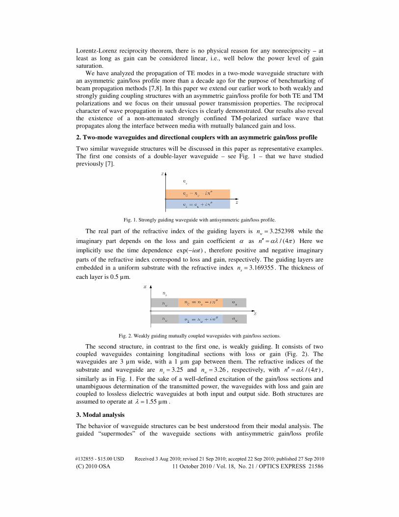
Two similar waveguide structures will be discussed in this paper as representative examples. The first one consists of a double-layer waveguide – see Fig. 1 – that we have studied previously [7].
Fig. 1. Strongly guiding waveguide with antisymmetric gain/loss profile.
The real part of the refractive index of the guiding layers is 3.252398w
n = while the
imaginary part depends on the loss and gain coefficient α as / (4 )n αλ π′′ = Here we
implicitly use the time dependence exp( )i tω− , therefore positive and negative imaginary
parts of the refractive index correspond to loss and gain, respectively. The guiding layers are embedded in a uniform substrate with the refractive index 3.169355
sn = . The thickness of
each layer is 0.5 µm.
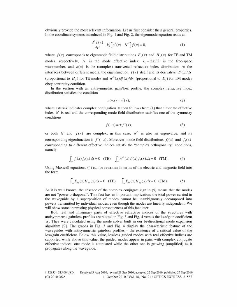
Fig. 2. Weakly guiding mutually coupled waveguides with gain/loss sections.
The second structure, in contrast to the first one, is weakly guiding. It consists of two coupled waveguides containing longitudinal sections with loss or gain (Fig. 2). The waveguides are 3 µm wide, with a 1 µm gap between them. The refractive indices of the substrate and waveguide are 3.25
sn = and 3.26
wn = , respectively, with / (4 )n αλ π′′ = ,
similarly as in Fig. 1. For the sake of a well-defined excitation of the gain/loss sections and unambiguous determination of the transmitted power, the waveguides with loss and gain are coupled to lossless dielectric waveguides at both input and output side. Both structures are assumed to operate at 1.55 µmλ = .
3. Modal analysis
The behavior of waveguide structures can be best understood from their modal analysis. The guided “supermodes” of the waveguide sections with antisymmetric gain/loss profile
#132855 - $15.00 USD Received 3 Aug 2010; revised 21 Sep 2010; accepted 22 Sep 2010; published 27 Sep 2010(C) 2010 OSA 11 October 2010 / Vol. 18, No. 21 / OPTICS EXPRESS 21586
obviously provide the most relevant information. Let us first consider their general properties. In the coordinate systems introduced in Fig. 1 and Fig. 2, the eigenmode equation reads as
2
2 2 202
( )( ) ( ) 0,
d f xk n x N f x
dx + − = (1)
where ( )f x corresponds to eigenmode field distributions ( )y
E x and ( )y
H x for TE and TM
modes, respectively, N is the mode effective index, 0 2 /k π λ= is the free-space
wavenumber, and ( )n x is the (complex) transversal refractive index distribution. At the
interfaces between different media, the eigenfunction ( )f x itself and its derivative ( )/df x dx
(proportional to z
H ) for TE modes and 2( ) ( )/n x df x dx− (proportional to z
E ) for TM modes
obey continuity condition. In the section with an antisymmetric gain/loss profile, the complex refractive index
distribution satisfies the condition
*( ) ( ),n x n x− = (2)
where asterisk indicates complex conjugation. It then follows from (1) that either the effective index N is real and the corresponding mode field distribution satisfies one of the symmetry conditions
*( ) ( ),f x f x− = ± (3)
or both N and ( )f x are complex; in this case, *N is also an eigenvalue, and its
corresponding eigenfunction is *( )f x− . Moreover, mode field distributions 1( )f x and 2( )f x
corresponding to different effective indices satisfy the “complex orthogonality” conditions, namely
21 2 1 2( ) ( ) 0 (TE), ( ) ( ) ( ) 0 (TM).f x f x dx n x f x f x dx
∞ ∞ −
−∞ −∞= =∫ ∫ (4)
Using Maxwell equations, (4) can be rewritten in terms of the electric and magnetic field into the form
1 2 1 2( ) ( ) 0 (TE), ( ) ( ) 0 (TM).y x x y
E x H x dx E x H x dx∞ ∞
−∞ −∞= =∫ ∫ (5)
As it is well known, the absence of the complex conjugate sign in (5) means that the modes are not “power orthogonal”. This fact has an important implication: the total power carried in the waveguide by a superposition of modes cannot be unambiguously decomposed into powers transmitted by individual modes, even though the modes are linearly independent. We will show some interesting physical consequences of this fact later.
Both real and imaginary parts of effective refractive indices of the structures with antisymmetric gain/loss profiles are plotted in Fig. 3 and Fig. 4 versus the loss/gain coefficient α . They were calculated using the mode solver built in our bi-directional mode expansion algorithm [9]. The graphs in Fig. 3 and Fig. 4 display the characteristic feature of the waveguides with antisymmetric gain/loss profiles – the existence of a critical value of the loss/gain coefficient. Below this value, lossless guided modes with real effective indices are supported while above this value, the guided modes appear in pairs with complex conjugate effective indices: one mode is attenuated while the other one is growing (amplified) as it propagates along the waveguide.
#132855 - $15.00 USD Received 3 Aug 2010; revised 21 Sep 2010; accepted 22 Sep 2010; published 27 Sep 2010(C) 2010 OSA 11 October 2010 / Vol. 18, No. 21 / OPTICS EXPRESS 21587
Fig. 3. Dependence of the effective indices of guided modes of the loss/gain waveguide plotted in Fig. 1 on the loss/gain coefficient α. a) real part, b) imaginary part. Red solid lines: TE modes, blue dots: TM modes.
Fig. 4. Dependence of the effective indices of guided modes of the loss/gain waveguide plotted in Fig. 2 on the loss/gain coefficient α. a) real part, b) imaginary part. Red solid lines: TE modes, blue dots: TM modes.
At the critical value, both effective indices merge into a single (real) value. Surprisingly enough – the field distributions also become identical but they still satisfy the orthogonality condition (4). These effects take place for both TE and TM polarization. As it could be expected, the difference between the effective indices of TE and TM modes is larger for more strongly guiding structure shown in Fig. 1. Note that in the strongly guiding structure in Fig. 1, the second mode appears only for some nonzero value of the loss/gain coefficient, for very small α values the waveguide is single-mode. Moreover, as it is evident from Fig. 3, this structure supports also propagation of yet another TM polarized mode with real effective refractive index. It corresponds to a confined surface mode propagating without attenuation along the surface between the media with a balance of loss and gain. The properties of such a mode will be discussed in detail later.
In Fig. 5 and Fig. 6 we plot the transversal distributions of magnetic fields 1,2( )H x of the
two TM guided modes of both structures. Field distributions of TE modes do not differ substantially. It is easy to verify that the field distributions exhibit all the symmetries discussed above: as long as the effective refractive index is real, the moduli of the field distributions are symmetric while their phase distributions are antisymmetric. The fields of modes with mutually complex conjugate effective indices satisfy the condition
*2 1( ) ( )f x f x= − , or, alternatively, 2 1 2 1( ) ( ) , arg{ ( )} arg{ ( )}.f x f x f x f x= − = − −
#132855 - $15.00 USD Received 3 Aug 2010; revised 21 Sep 2010; accepted 22 Sep 2010; published 27 Sep 2010(C) 2010 OSA 11 October 2010 / Vol. 18, No. 21 / OPTICS EXPRESS 21588
Fig. 5. Magnetic field distribution of TM-polarized guided modes in the gain/loss waveguide in Fig. 1. Solid lines – magnitude, dashed – phase in radians. a) loss/gain coefficient α = 0.5 µm–1, i.e. below the critical value, b) α = 0.7 µm–1, i.e. above the critical value.
Fig. 6. Magnetic field distribution of two TM-polarized guided modes in the gain/loss directional coupler structure in Fig. 2. Notation same as in Fig. 5. a) – loss/gain coefficient α = 30 cm–1 (below the critical value), b) α = 120 cm–1.(above the critical value).
The slopes of the phase distributions of the eigenmodes clearly indicate that in all these modes power flows from the layer with gain to the lossy layer; the phase front of the lossless modes in the “cladding” is perpendicular to the propagation direction, in accordance with their lossless character. All power generated in the layer with gain is absorbed in the lossy layer. Modes with complex effective indices are described in the lossless “cladding” by complex exponentials: power of lossy modes flows predominantly from the cladding into the lossy layer where it is absorbed while for modes with gain, the “active” (gain) layer feeds all other layers with power.
4. Power transmission in a coupler with balanced loss and gain
Let us now consider simultaneous propagation of two modes in a directional coupler with balanced loss and gain section shown in Fig. 2. To demonstrate the behavior of the structure in different regimes we performed a series of numerical modeling exercises with our code [9]. The waveguides with loss and gain were separately excited by a single lossless dielectric waveguide, and the output power was monitored successively with a single (lossless) dielectric waveguide attached to the channel with loss or gain, and then by a pair of lossless waveguides attached to both lossy and active waveguides. All modeled waveguide configurations are schematically plotted in Fig. 7.
#132855 - $15.00 USD Received 3 Aug 2010; revised 21 Sep 2010; accepted 22 Sep 2010; published 27 Sep 2010(C) 2010 OSA 11 October 2010 / Vol. 18, No. 21 / OPTICS EXPRESS 21589
Fig. 7. Waveguide configurations investigated numerically. Gray – lossless waveguide, light red – waveguide with gain, light blue – lossy waveguide. Numbers and numbers primed denote the input and output waveguides, respectively.
At the first glance this procedure looks unnecessarily complicated, but the opposite is true. As long as more than a single mode is excited in the section with loss and gain, it is not possible to distinguish power transmitted by individual modes. Moreover, lossless input waveguides inevitably excite in the loss/gain section also radiation modes since the guided modes of different longitudinal sections are not perfectly mutually matched. To avoid these uncertainties, the transmitted power of a single waveguide is determined as power coupled into a (single mode lossless) output waveguide that is successively attached to the waveguides with loss and gain, and the total transmitted power is determined as a sum of powers carried by symmetric and antisymmetric modes of a pair of lossless waveguides attached to both waveguides with loss and gain.
Fig. 8. Magnetic field distribution 2| ( , )|
yH x z in waveguide structures c) and f) in Fig. 7
for160 cmα −= . The length of the gain/loss section is 4000 µm. a) excitation into the lossy
waveguide 1 (configuration c), b) excitation into the waveguide 2 with gain (configuration f).
Fig. 9. Magnetic field distribution 2| ( , )|
yH x z excited in structures c) and f) in Fig. 7 for
1100 cmα −= . The length of the gain/loss section is 250 µm. a) excitation into the lossy waveguide 1 (configuration c), b) excitation into the waveguide 2 (with gain – configuration f). Note the difference between the color scales in figs. a) and b); the excitation amplitude is in both cases identical.
#132855 - $15.00 USD Received 3 Aug 2010; revised 21 Sep 2010; accepted 22 Sep 2010; published 27 Sep 2010(C) 2010 OSA 11 October 2010 / Vol. 18, No. 21 / OPTICS EXPRESS 21590
Let us first discuss the field distribution in the structures with the configurations c) and f)
of Fig. 7. Calculated relative distributions of the TM field 2| ( , )|y
H x z are plotted in Fig. 8 for
the loss/gain coefficient 160 cmα −= (below the critical value) and in Fig. 9 for 1100 cmα −= (above the critical value). It is evident from Fig. 8 that for any kind of excitation, light is coupled between the waveguides with loss and gain periodically but asymmetrically – the maxima in one waveguide do not correspond to minima in the other waveguide. It indicates that the total power transmitted in the coupler with balanced loss and gain is not constant along the coupler. It is demonstrated in Fig. 10 (a) where power coupled into output waveguides is plotted versus the length of the coupler with loss and gain. Power coupled into individual output waveguides 1’ and 2’ ( 11 22 12, , and P P P′ ′ ′ ) oscillates periodically as the
coupler length is increased, but so does also the total power coupled into both output waveguides, 1tot 2tot, P P (the first number in the subscripts denotes the excitation waveguide).
In this particular case it changes with length c
L more than four times. The distribution of
output power between the output waveguides is different for excitation by waveguide 1 and 2 but the minimum and maximum values of the output power are in both cases the same.
The coupler behaves very differently above the critical value of the gain/loss coefficient. Both the decaying and growing “supermodes” are excited by any of the exciting waveguides 1 or 2 but after a short length of propagation, the growing mode becomes dominant.
Fig. 10. Power transmitted by the directional coupler section with balanced loss and gain
versus the coupler length c
L . a) 160 cmα −= (below the critical value), b)
1100 cmα −= (above the critical value).
The power transmission as a function of the coupler length shown in Fig. 10(b) confirms this behavior – it essentially grows exponentially with coupler length except for short lengths where the attenuated mode still plays an important role.
Numerical modeling also unambiguously confirmed our statement included in the Introduction in which we claim that power transmission in waveguide structure with an asymmetric gain/loss profile is reciprocal; in particular, power transmission coefficients from the input waveguide 1 into the output waveguide 2’ and vice versa are always identical.
5. Surface mode
The field distribution of the mode supported by the waveguide structure in Fig. 1 for the very
high loss/gain coefficient 112 µmα −= was numerically calculated using the computer code
[9] and is plotted in Fig. 11. It is obvious that it corresponds to a strongly confined surface wave localized at the interface between the layers with loss and gain. Its field is very weak outside these layers. We can thus approximately substitute the layers with loss and gain with
#132855 - $15.00 USD Received 3 Aug 2010; revised 21 Sep 2010; accepted 22 Sep 2010; published 27 Sep 2010(C) 2010 OSA 11 October 2010 / Vol. 18, No. 21 / OPTICS EXPRESS 21591
semi-infinite media and consider only the interface between them. In this approximation, the magnetic field distribution of the surface wave is assumed to be of the form
[ ][ ]
0 0 SWSW
0 0 SW
exp ( ) , 0,( , )
exp ( ) , 0,L
G
H ik x N z xH x z
H ik x N z x
γγ− + <
= + >
(6)
where
2 2 2 2
SW SW, ,
, .
G G L L
G w L w
n N n N
n n in n n in
γ γ= − = −
′′ ′′= − = + (7)
and SWN is the effective refractive index of the mode. The signs of the square roots in (7)
have to be chosen so that the field decays exponentially in both directions with the distance from the interface. It requires imaginary parts of both
Gγ and
Lγ to be positive.
Fig. 11. Magnetic field distribution of the TM polarized surface mode in the gain/loss
waveguide in Fig. 1 for 112.5 µmα −= . Solid line – magnitude, dashed – phase (in
radians). a) transversal field distribution, b) 2D field distribution SWRe{ ( , )}H x z .
From the continuity condition of 2SW( ) ( ) ( )/
zE x n x dH x dx−
∼ at the interface 0x = it
follows that
2 2.G G L Ln nγ γ− −= − (8)
By solving this equation with respect to the effective index N one obtains the following simple formula
2 2 2 2
SW 2 2 2 2
( ),
2 ( )
L G w
L Gw
n n n nN
n n n n
′′+= =
+ ′′ −
(9)
(keep in mind that n′′± is the imaginary part of the refractive index of the loss/gain medium). Note that as long as
wn n′′ < , SWN is a real value. Therefore, the corresponding surface mode
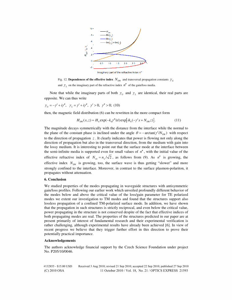
propagates without any attenuation. Values calculated using (9) are plotted in Fig. 3 as empty circles. A perfect agreement with the solution of the rigorous dispersion equation for the original layered structure is evident. We note that the first equation in (9) is formally identical with the expression for the effective index of the surface plasmon-polariton propagating along the metal-dielectric interface [10], and also for the Zenneck surface wave [11]. In Fig. 12 we present the dependences of the effective index SWN and of the transversal propagation
constants Gγ and
Lγ vs. the imaginary part of the refractive index of the gain/loss media.
#132855 - $15.00 USD Received 3 Aug 2010; revised 21 Sep 2010; accepted 22 Sep 2010; published 27 Sep 2010(C) 2010 OSA 11 October 2010 / Vol. 18, No. 21 / OPTICS EXPRESS 21592
Fig. 12. Dependences of the effective index SWN and transversal propagation constants Gγ
and Lγ on the imaginary part of the refractive index n′′ of the gain/loss media.
Note that while the imaginary parts of both Gγ and
then, the magnetic field distribution (6) can be rewritten in the more compact form
[ ]SW 0 0 0 SW( , ) exp( | |)exp ( ) .H x z H k x ik x N zγ γ′′ ′= − − + (11)
The magnitude decays symmetrically with the distance from the interface while the normal to the plane of the constant phase is inclined under the angle SWarctan( / )Nθ γ ′= − with respect
to the direction of propagation z . It clearly indicates that power is flowing not only along the direction of propagation but also in the transversal direction, from the medium with gain into the lossy medium. It is interesting to point out that the surface mode at the interface between the semi-infinite media is supported even for small values of n′′ , with the initial value of the
effective refractive index of sw / 2w
N n= , as follows from (9). As n′′ is growing, the
effective index SWN is growing, too, the surface wave is thus getting “slower” and more
strongly confined to the interface. Moreover, in contrast to the surface plasmon-polariton, it propagates without attenuation.
6. Conclusion
We studied properties of the modes propagating in waveguide structures with antisymmetric gain/loss profiles. Following our earlier work which unveiled profoundly different behavior of the modes below and above the critical value of the loss/gain parameter for TE polarized modes we extent our investigation to TM modes and found that the structures support also lossless propagation of a confined TM-polarized surface mode. In addition, we have shown that the propagation in such structures is strictly reciprocal, and even below the critical value, power propagating in the structure is not conserved despite of the fact that effective indices of both propagating modes are real. The properties of the structures predicted in our paper are at present primarily of interest of fundamental research and their experimental verification is rather challenging, although experimental results have already been achieved [6]. In view of recent progress we believe that they trigger further effort in this direction to prove their potentially practical importance.
Acknowledgements
The authors acknowledge financial support by the Czech Science Foundation under project No. P205/10/0046.
#132855 - $15.00 USD Received 3 Aug 2010; revised 21 Sep 2010; accepted 22 Sep 2010; published 27 Sep 2010(C) 2010 OSA 11 October 2010 / Vol. 18, No. 21 / OPTICS EXPRESS 21593