24
WaveRunner ® Xi-A Series Performance Reimagined 400 MHz to 1 GHz Performance Reimagined 400 MHz to 1 GHz

WaveRunner® Xi-A Series
Performance Reimagined400 MHz to 1 GHzPerformance Reimagined400 MHz to 1 GHz
2
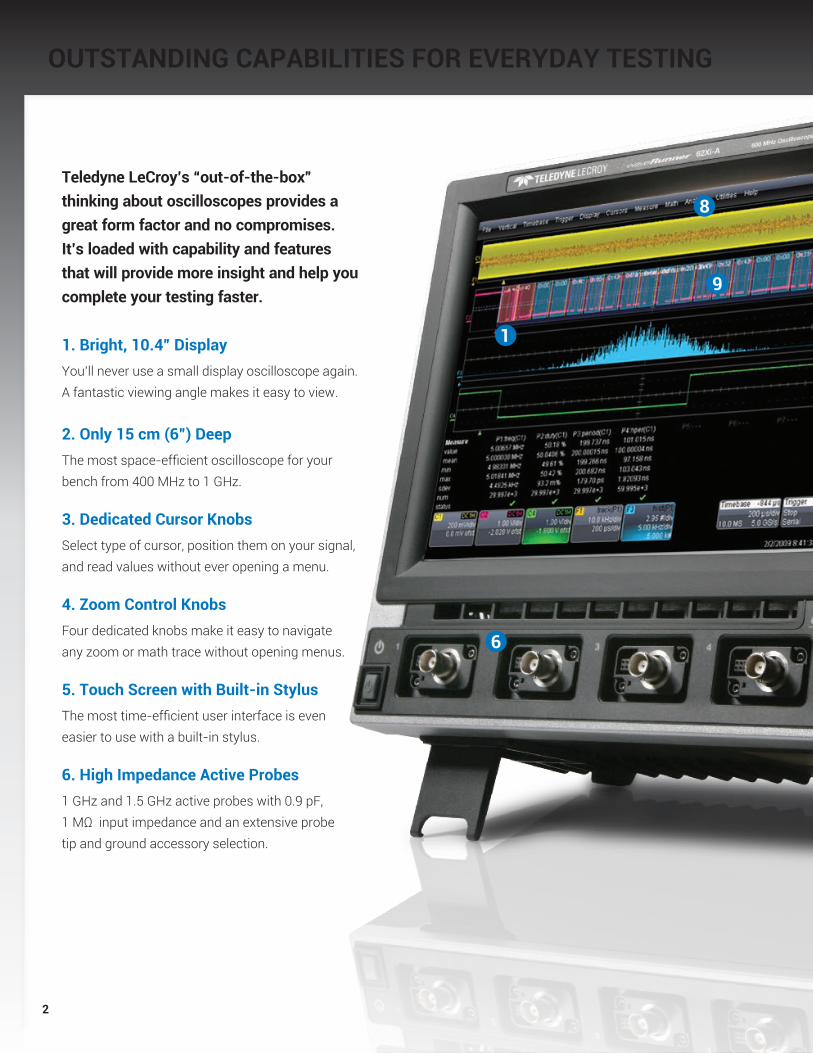
OUTSTANDING CAPABILITIES FOR EVERYDAY TESTING
1
8
9
6
Teledyne LeCroy’s “out-of-the-box” thinking about oscilloscopes provides a great form factor and no compromises. It’s loaded with capability and features that will provide more insight and help you complete your testing faster.
1. Bright, 10.4” DisplayYou’ll never use a small display oscilloscope again. A fantastic viewing angle makes it easy to view.
2. Only 15 cm (6”) DeepThe most space-efficient oscilloscope for your bench from 400 MHz to 1 GHz. 3. Dedicated Cursor Knobs Select type of cursor, position them on your signal, and read values without ever opening a menu. 4. Zoom Control Knobs Four dedicated knobs make it easy to navigate any zoom or math trace without opening menus. 5. Touch Screen with Built-in StylusThe most time-efficient user interface is even easier to use with a built-in stylus. 6. High Impedance Active Probes1 GHz and 1.5 GHz active probes with 0.9 pF, 1 MΩ input impedance and an extensive probe tip and ground accessory selection.

3
7
10
43
2
7. Teledyne LeCroy WaveStream™ Fast Viewing Mode
Provides a lively, analog-like feel similar to a phosphor trace. Adjust “trace” intensity with the front panel control, or toggle between Teledyne LeCroy WaveStream and real-time modes.
8. Teledyne LeCroy WaveScan™ Advanced Search & Analysis
Use more than 20 modes to capture and search, or “scan” for anomalous events over thousands or millions of acquisitions. Use ScanHisto or ScanOverlay to display intuitive scanned results.
9. Serial Triggering & Decoding I2C, SPI, UART, RS-232, AudioBus (I2S, LJ, RJ, TDM), CAN, LIN, FlexRay,™ and MIL-STD-1553 serial triggers, available for WaveRunner Xi-A.
10. “Push” Knobs Trigger level, delay, and offset knobs all provide shortcuts to common actions when pushed.
11. Local Language User InterfaceSelect from 10 language preferences. Add a front panel overlay with your local language.
5

4
Enhanced Understanding of Serial Data SignalsTrigger on I2C, SPI, UART, RS-232, AudioBus (I2S, LJ, RJ, TDM), CAN, LIN, FlexRay or MIL-STD-1553 serial data patterns. Intuitively decode values on the oscilloscope grid.
Powerful Triggers Isolate EventsAn extensive collection of SMART, Serial, and Digital (MS Series) triggers enables users to quickly and easily isolate events of interest (some optional).
WaveStream™ Fast Viewing ModeUse the high sampling rate and WaveStream fast viewing mode to characterize signal shape, rise time, overshoot, etc., and verify the presence or absence of high-speed transients.
Advanced Acquisition ModesSequence Mode allows you to partition your acquisition memory into segments and capture specific events over long periods of time. Then, view and analyze each segment individually.
COMPLETE CAPABILITY—100% TEST COVERAGE
The WaveRunner Xi-A is the
most powerful and capable
scope available in its class.
Basic system validation using
advanced triggers, fast view-
ing modes, measurement
parameters, or serial decodes
is simple and easy. Advanced
debug, multi-domain analysis,
and waveshape analysis are
possible with tools unique
to WaveRunner Xi-A.
Optional application packages
help you make sense of
well-defined problems.
Completely CustomizableQuickly create your own measurement parameters or math functions using Excel, MATLAB,® or VBScripts (some capability optional).
WaveScan™ Advanced Search and AnalysisWaveScan provides the ability to locate unusual events in a single capture, or scan for an event in many acquisitions over a long period of time using more than 20 different search/scan modes. Use ScanHisto or ScanOverlay to display intuitive scanned results.

5
Beyond Time Domain AnalysisAmplify your understanding with multidomain analysis of your signals. Convert signal information into Statistical domain (Histogram), Spectral domain (long memory FFTs), Jitter, Modulation, or other Measurement Parameter domains (Tracks of measurement parameters). (Some capability is optional.)
Integrated Tool SetsTeledyne LeCroy math, measure, and analysis tools are tightly integrated with basic scope operations. It’s easy to link capabilities and expand understanding. Free yourself from constraints!
Advanced Application PackagesUse a variety of application packages to provide detailed, fast solutions for specific problems.
Fast Long Memory with Front Panel Zoom ControlsWaveRunner Xi-A’s long memory is optimized for calculation of more information 10–100x faster than other oscilloscopes, while enabling easy access to simple zooming and positioning from the front panel.
Extensive Math and Measurement CapabilityMore standard and optional measure-ments and more powerful math capa-bility are provided with results returned faster than in other oscilloscopes.
Complete Probing SolutionsA wide variety of active FET probes, current probes, differential probes, HV probes, etc. with complete tip and ground accessories make it easy to probe your signals.
Mixed Signal Oscilloscope OptionThe MS Series can capture digital signals with speeds up to 500 MHz. View up to 36 digital channels with up to 50 Mpts/Ch memory and analyze analog and digital events together.
Power/Amplifier MeasurementsExcellent overdrive recovery and signal integrity make WaveRunner Xi-A ideal for high-voltage switching loss, conduction loss, ripple, switching power supply, and other amplifier measurements. Use with Teledyne LeCroy Differential Amplifiers for high-performance 100,000:1 Common-Mode Rejection Ratio.
Timing CharacterizationExtensive triggers allow fast event isolation. Measure timing statistically and view behavior graphically using histograms. Gain real understanding of root cause.
Slow/High-speed Signal MixLong memory, HFREJ trigger coupling, built-in noise filtering, etc. enable fast understanding of signal behavior in circuits with a mix of slow-speed (sensor, actuator, power supply, mechanical) and high-speed signals.

6
THE MOST COMPLETE PROBLEM SOLVING OSCILLOSCOPES
WaveRunner Xi-A
is the most complete “problem
solving” oscilloscope from 400 MHz to
1 GHz with great performance, an unbeliev-
able big display/small footprint form factor, and a
multitude of fast viewing, SMART/serial data triggering,
scanning, and WaveShape Analysis capabilities for fast or
slow signals. No matter what your need, you can put the precision,
performance, and capability of WaveRunner Xi-A to work for you.
Great PerformanceWith 5 GS/s and 12.5 Mpts standard
on every channel (up to 10 GS/s
interleaved with 64Xi-A and 104Xi-A),
you can be assured of precise
measurements of fast signals, and
long captures of slow-speed events.
Big Display/Small FootprintA big display is crucial to understand-
ing circuit behaviors, especially when
working with a combination of analog,
digital, and serial data signals. That’s
why we use a big, bright 10.4” color
display to allow room for everything,
including time-correlated views of
mixed-signal systems and non-time
domain analysis. You’ll love the
impressive display viewing angle;
and the very small instrument footprint
makes it easy to work anywhere.
Powerful WaveShape Analysis CapabilityWaveRunner Xi-A has the best
problem-solving capability, whether
you are gathering statistical data
on thousands or millions of events,
converting signal information into a
statistical, modulation, or frequency
domain for better understanding, or
using WaveScan™ to find anomalous
events. In addition, WaveRunner
Xi-A’s has numerous application
packages to solve specific test and
measurement challenges.
7
THE MOST COMPLETE PROBLEM SOLVING OSCILLOSCOPES
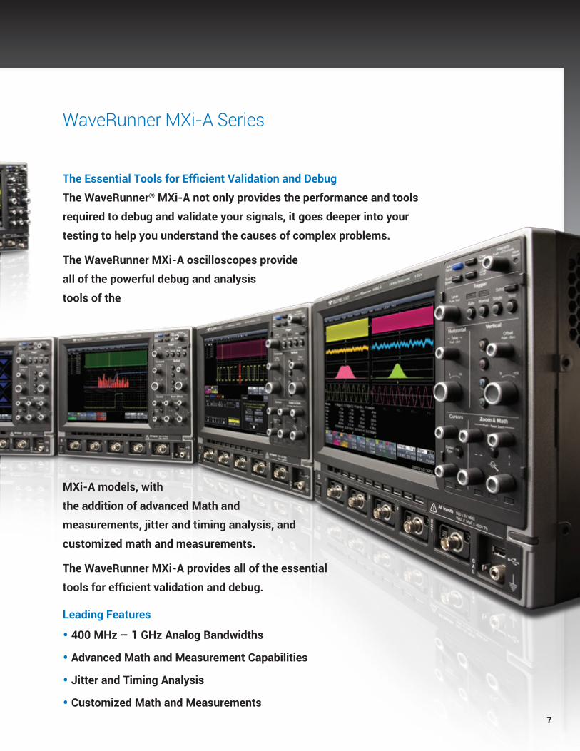
The Essential Tools for Efficient Validation and Debug
The WaveRunner® MXi-A not only provides the performance and tools
required to debug and validate your signals, it goes deeper into your
testing to help you understand the causes of complex problems.
The WaveRunner MXi-A oscilloscopes provide
all of the powerful debug and analysis
tools of the
MXi-A models, with
the addition of advanced Math and
measurements, jitter and timing analysis, and
customized math and measurements.
The WaveRunner MXi-A provides all of the essential
tools for efficient validation and debug.
Leading Features
• 400 MHz – 1 GHz Analog Bandwidths
• Advanced Math and Measurement Capabilities
• Jitter and Timing Analysis
• Customized Math and Measurements
WaveRunner MXi-A Series

8
EMBEDDED CONTROLLER VALIDATION AND DEBUG
Teledyne LeCroy’s powerful WaveRunner Xi-A oscilloscopes can be turned into high-performance mixed signal oscilloscopes (MSOs) with the addition of the MS-500 or MS-250 mixed signal oscilloscope options. In addition, I2C, SPI, UART, RS-232, AudioBus (I2S, LJ, RJ, TDM), CAN, LIN, FlexRay, and MIL-STD-1553 triggering |and decoding options turn the WaveRunner Xi-A into an all-in-one analog, digital, and serial data trigger, acquisition, and analysis machine.
High-performance Mixed Signal CapabilitiesEmbedded controller design and debug involves capturing and viewing a number of different types of signals. These signals are typically a mix of ana-log, digital, and serial data waveforms from a combination of analog sensors, microcontrollers and peripheral devices. With the ability to capture digital signals with speeds up to 500 MHz and long
memory of 50 Mpts/Ch the MS-500 provides unmatched mixed signal performance. For added flexibility the MS-500 supports 36 channels allowing you to view all the signals if a 16-bit micro controller plus some control lines. For applications not requiring the highest performance the MS-250 is a great value, providing 250 MHz maximum signal speed, 18 channels and 10 Mpts/Ch.
Extensive TriggeringThe MS-500 and MS-250 enhance the WaveRunner Xi-A trigger capabili-ties. Normal oscilloscope triggers will operate on digital inputs. Cross-pattern triggering allows for simple or com-plex trigger patterns to be setup with any combination of analog and digital channels. Event triggering can be configured to arm on an analog signal and trigger on a digital pattern.
Quick Mixed Signal Setup, Easy-to-useUnlike a traditional Logic Analyzer, the MS-500 and MS-250 are easy to use. A simple connection links the oscilloscope with the digital inputs so users can start viewing signals and begin debugging quickly. In addition, all standard oscilloscope tools are read-ily accessible. Signal debug is simple, using standard oscilloscope tools, such as cursors, measurement parameters, and zooming.

9
Complete I2C, SPI, UART, RS-232, AudioBus (I2S, LJ, RJ, TDM), CAN, LIN, FlexRay, and MIL-STD-1553 Serial TriggeringQuickly and easily isolate specific serial data events on your embedded controller for better understanding and faster debug. Set up trigger conditions in binary, hexadecimal (Symbolic for CAN) formats. Use the MS-500 or MS-250 to capture serial data busses keeping the analog oscilloscope chan-nels open for other uses. Trigger on DATA in specific locations of long I2C EEPROM reads. Get complete control of your debug process and finish faster.
Powerful Conditional Data TriggeringCompletely isolate specific message events for better understanding and debug. Use a conditional I2C SPI, UART, RS-232, AudioBus (I2S, LJ, RJ, TDM),
CAN, LIN, FlexRay, and MIL-STD-1553 DATA trigger to select a range of DATA values to trigger on, not just a single DATA value. Oftentimes, I2C utilizes DATA bytes to specify sub-addresses for accessing memory locations in EEPROMs. Conditional DATA trigger allows triggering on a range of DATA bytes that correspond to reads or writes to specific sub-address memory blocks in the EEPROM. It can also aid in monitoring DATA outputs from sensors, such as analog-to-digital converters, and triggering when DATA is outside a safe operating range. In both cases, verifying proper operation becomes a simple task.
Intuitive, Color-Coded Decode OverlayAdvanced software algorithms decon-struct the waveform into binary, hex, or ASCII protocol information, then over-
lay the decoded data on the waveform. Various sections of the protocol are color-coded to make it easy to under-stand. The decode operation is fast—even with long acquisitions.
Table Summary and Search/ZoomTurn your oscilloscope into a protocol analyzer with the Table display of protocol information. Customize the table, or export Table data to an Excel file. Touch a message in the table and automatically zoom for detail. Search for specific address or data values in the acquisition.

10
EXCELLENCE IN ACQUISITION
SMART Triggers Isolate Events The WaveRunner Xi-A oscilloscope provides a multitude of basic and advanced (SMART) triggers to meet any need. Advanced triggers isolate specific events of interest, and (when combined with long memory) provide a complete view of the signal activity around that event. WaveRunner Xi-A excels in this regard.
Trigger on what you expect (widths, glitches, video, logic patterns, etc.) and also trigger on unusual signals (dropouts, intervals, runts, slew rates). Teledyne LeCroy’s exclusion triggering can ex-clude normal signals and capture only the abnormal ones, speeding up the debug of your circuits and systems. Trigger on signals down to 1 ns in width (500 ps for width and glitch trigger), or use an “A” condition to qualify a “B” trigger.
TriggerScan™TriggerScan uses high-speed hardware triggering capability with persistence displays to capture only the signals of interest and provide answers up to 100x faster that other methods. Traditional fast display update modes work best on frequent events occurring on slow edge rates while TriggerScan excels in finding infrequent events on fast edge rates.
Since hardware triggering is used to capture only the elusive events, TriggerScan is more effective at finding anomalies quickly compared to simple display technologies.
A built-in automated Trigger Trainer analyzes the waveforms, identifies normal behavior, and then sets up a large set of rare event smart trigger setups that target abnormal behav-ior. It then rapidly sequences through each individual trigger with a user- defined dwell time, and captures and displays any anomalous signals that meet the trigger conditions.
Sequence Mode Extends Long Memory and SMART Triggering CapabilityUse Sequence mode to store up to 5,000 triggered events as “segments” into oscilloscope memory. This can be ideal when capturing many fast pulses in quick succession (i.e., trigger re-arm time is most important) or when capturing few events separated by long time periods (i.e., longest capture time is most important).
Sequence mode can acquire 4 channels simultaneously, provide timestamps for each acquisition (to 1 ns resolution), minimize capture dead-time (to ≤1 µs), and allow various ways to view and analyze the captured segmented data.
Combine sequence mode with an advanced trigger to isolate a rare event, capture all instances over hours or days, and view and analyze each event afterwards.
X-Stream II Architecture
Optimized for Fast ThroughputX-Stream II architecture enables high throughput of data. X-Stream II uses variable waveform segment lengths to enable all processing intensive calculations to take place in fast CPU cache memory, thus improving calculation speed and efficiency. The result—faster processing compared to other oscilloscopes.
Optimized for Long MemoryX-Stream II essentially has no analysis memory length restrictions, regardless of analysis type, since the variable waveform segment length can always be limited to a size that can fit in CPU cache memory. Other oscilloscopes with conventional architectures cannot make this claim, and often have limitations on analysis memory of 5–20% the length of their acquisition memory under the best conditions.
Optimized for ResponsivenessBy dynamically allocating buffers to maximize memory availability, the WaveRunner Xi-A Series embodies the fastest front panel responsiveness. A built-in processing abort makes front panel control changes instant by stop-ping the current process and allowing new waveforms to be positioned or zoomed— all without a lengthy recalculation. Meanwhile, waveform previewing shows interim calculation results.

11
Teledyne LeCroy WaveStream™ Fast Viewing ModeWaveStream provides a vibrant, intensity graded (256 levels) display with a fast update to closely simulate the look and feel of an analog oscillo-scope. WaveStream is most helpful in viewing signals that have signal jitter or signal anomalies, or for applying a visual check before creating an advanced trigger or WaveScan setup to locate an unusual event.
Since the sample rate in WaveStream mode can be as high as 10 GS/s (up to 5x that of other oscilloscopes), it is an excellent runt or glitch finder. Timing jitter is often visually assessed to understand approximate behavior. WaveStream makes it easy to under-stand jitter on edges or in eye diagrams. WaveStream also excels in allowing you to relate composite (WaveStream) to single-event (real-time sampled) behaviors. Just capture in WaveStream mode, toggle to view or zoom a single trace, then toggle back to WaveStream mode.
WaveScan™ Advanced Search and Analysis Finds Problems that Triggers Won’t Find. The best trigger won’t find all unusual events—a more powerful capability is sometimes needed. WaveScan provides the ability to locate unusual events in a single capture (i.e., capture and search), or “scan” for an event in many acquisitions over a long period of time. Select from more than 20 search modes (frequency, rise time, runt, duty cycle, etc.), apply a search condition and begin scanning. Since the scanning “modes” are not simply copies of the hardware triggers, the utility and capability is much higher. For instance, there is no “ frequency” trigger in any oscilloscope, yet WaveScan allows “frequency” to be quickly “scanned” for. This allows the user to accumulate a data set of unusual events that are separated by hours or days, enabling faster debugging.
When used in multiple acquisitions, WaveScan builds on the traditional Tele-dyne LeCroy strength of fast processing of data. A Teledyne LeCroy X-Stream oscilloscope will quickly “scan” millions of events, looking for unusual occur-rences, and do it much faster and more efficiently than other oscilloscopes can.
WaveScan in WaveRunner Xi-A also contains ScanHisto and ScanOverlay capability. Found events can be overlaid in a ScanOverlay view to provide a quick and simple comparison of events. In addition, measurement-based scanning modes (like the frequency example given above), permit ScanHisto-grams to show the statistical distribution of the found events. These analysis tools simplify understanding and enable faster debug.

12
UNMATCHED MEASUREMENT AND VALIDATION CAPABILITY
Oftentimes, only viewing signals does not provide the level of precision that is required for validating designs. At those times, the ability of WaveRunner Xi-A to quickly provide precise statistical data becomes vital. With WaveRunner Xi-A,
you can quickly accumulate data on thousands of measurements in a single shot (WaveRunner Xi-A does not limit its measurements to a single value in an acquisition) or in multiple acquisitions.
Touch a button, and display statistical information. Touch another button to
display a Histicon graphical view of the measurement distribution. Expand this view into a larger histogram of measurement data. Accumulate up to 2 billion measure-ment events, or create measurable per-sistence traces of signals with the optional WRXi-STAT.
WaveRunner Xi-A provides the
highest value for everyday
characterization, validation,
and debug, and the best
capability for quickly debug-
ging advanced problems.
Whether you are debugging
circuits with a mix of slow-
and high-speed signals,
performing signal integrity
checks on high-speed clock
and data signals, or doing ad-
vanced debugging of complex
problems, WaveRunner Xi-A
has the right toolset that is
easily applied to the problem.
Advanced Math Characterization Most oscilloscopes contain only a few simple math functions to subtract waveforms or to perform coarse resolution FFTs on short record length acquisitions. Or, they provide long memory, but limited ability to process the memory and perform WaveShape
Analysis that leads to detailed under-standing and faster debug.
WaveRunner Xi-A oscilloscopes contain dozens of standard math functions, and powerful capabilities, such as long memory FFTs, Trend-ing, Tracking (optional), Sparsing, Interpolation selection, a variety of
Persistence Views, user customized math and measurements (MATLAB or Visual Basic formats), and numerous other specialized capabilities (optional Application Packages). The toolset is rich and deep, and sure to solve any complex problem.

13
LABNOTEBOOK™ A UNIQUE TOOL FOR DOCUMENTATION AND REPORT GENERATION
The LabNotebook feature of WaveRunner Xi-A provides a report generation tool to save and document all your work. Saving all displayed waveforms, relevant WaveRunner Xi-A settings, and screen images is all done through LabNotebook, eliminating the need to navigate multiple menus to save all these files independently.
The screen images saved can be annotated with freehand notes using the stylus and touch screen, and then included in your report.
The WaveRunner Xi-A touch screen and stylus allow for easy annotation of the screen. LabNotebook allows you to add freehand text and graph-ics in multiple colors along with printed text and arrows to help identify important parts of your waveforms and measurements.
V/divT/div
Memory LengthSample RateMeasurement
Math
WAVEFORM
OSCILLOSCOPE SET UP
SCREEN DUMP
PRINTER
HARD DRIVE
USB DRIVE
Document Your Work One-touch Functionality Save Your Work Recall Jobs
Easy report generation helps you share your findings and communicate
important results.
LabNotebook adds a simple way to report your work and save all essential
waveforms, settings, and screen images.
Quickly save all the necessary files with LabNotebook in a
single button press.
Recall your settings from any report
by using the Flashback capability.
FLAS
HBAC
KFL
ASHB
ACK
FLAS
HBAC
K
LABNOTEBOOK

14
Trend Views Turn Your Oscilloscope Into a Strip Chart RecorderSlowly sample at 1000 seconds/div to capture hours of slow speed signal data. Using Trend Views, plot measurement values of high-speed signals with slower speed signals, such as transducer or voltage values.
Track Views Provide Graphical Display of Parameter Values vs. TimeTrack in WaveRunner Xi-A (optional) uses every instance of a measurement in an acquisition to create a plot of measurement values on the Y-axis and time on the X-axis. The result is a graphical plot of a measurement
change time-correlated to the original channel acquisition—perfect for intuitive understanding.
Some examples include:
• Measuring a signal’s Frequency over a 100 ms interval, and under-standing whether the correct frequency shifts are present at the right times.
• Measuring a pulse width modulated (PWM) signal’s Width over a 1 second interval, and determining if the modulation circuit is correctly reacting to system changes.
• Measuring the cycle-cycle jitter values in a micro processor and understanding how cycle-cycle jitter peaks correlate to spikes in power supply lines.
The most difficult electrical circuit problems are rarely obvious in the time domain. Long memory with zooming, searching, and scanning is an important part of the solution. However, serious design professionals understand the importance of converting time-domain information into statistical, parameter, or frequency domains so as to get to the root of the problem quicker. WaveRunner Xi-A provides you with the tools necessary to understand complex circuit problems and solve them faster.
The PWM signal for a power tool motor speed controller is monitored during start-up. The Width parameter is used. All instances of Width during the acqui-sition are measured. Then, Track was applied to determine when the speed plateaued (i.e., when the tool rotation reached steady-state).
MULTIDOMAIN WAVESHAPE ANALYSIS IMPROVES UNDERSTANDING

15
Histograms Graphically Present Statistical DataTeledyne LeCroy oscilloscopes excel in capturing hundreds or thousands times more measurements per acquisition than other oscilloscopes do. With this much data, it is essential to provide more than just a list of mean, min, max, sdev, etc. Histograms provide an intuitive way to view the distribution of statistical data and gain real insight into underlying problems. For instance:
• Measure millions of jitter values in seconds, understand whether the measurement distribution is Gaussian or non-Gaussian, and correct timing problems to stay within a timing budget.
• Improve validation of timing bud-gets when measuring embedded controller response times. Measure hundreds of thousands of timing events instead of just hundreds, and easily view real-world worst-case timing situations.
Fast Fourier Transforms (FFTs) Provide Spectral Views for Advanced Troubleshooting
Teledyne LeCroy’s long memory (up to 25 Mpts) FFTs increase your ability to understand signal behaviors in the frequency domain. The long memory allows users to obtain 5–100x the frequency resolution possible with FFTs available in other oscilloscopes, which allows more precise trouble-shooting. Built-in averaging of FFTs helps to eliminate random events from the calculations. In addition, Teledyne LeCroy FFTs can be applied to any channel or math function, which greatly expands the ability to gather useful information.
Some examples include:
• Capture power supply, clock, and data signals with 1 kHz frequency resolution. Correlate power supply noise to signal integrity.
• Apply an FFT to a Track of Cycle-Cycle Jitter and gain insight into the frequency components and root cause of the jitter.
• Quickly capture hundreds of acquisitions and average the FFTs to increase frequency signal-noise ratio and to separate random from deterministic events.
A 200 MHz clock signal is acquired at 10 GS/s using 20 Mpts of acquisition data (400,000 cycles). Cycle-Cycle and Period Jitter are measured and analyzed with Tracks and Histograms. Cycle-Cycle jitter shows a distinctive modality. Other signals could now be acquired and time-correlated to understand the histogram modality.

16
SPECIFIC SOLUTIONS FOR TOUGH PROBLEMS
Power Analyzer SoftwarePackage (WRXI-PWR)Quickly measure and analyze operating characteristics of power conversion circuits. Make automatic switching device measurements and identify areas of loss and conduction with color-coded overlay. Control loop modulation analysis and line power harmonic testing are all simplified with a dedicated user interface.
Spectrum Analyzer Analysis Package (WRXi-SPECTRUM)SPECTRUM converts the controls of your oscilloscope to those of a spectrum analyzer. Adjust the frequency span, resolution and center frequency. Apply filtering to your signal and watch the frequency signature change in real time. A unique peak search labels spectral components and presents frequency and level in a table. Touch any line to move to that peak.
Automotive Solutions (CANbus TD, CANbus TDM, WRXi-FlexRaybus TD/TDP, WRXi-LINbus TD) Flexible trigger on CAN, FlexRay, or LIN bus messages. Decode and display hexidecimal data values next to the signal on the screen. Statistically analyze performance with histograms and determine root cause of timing irregularities. Vehicle Bus Analyzer (VBAs) provide CAN symbolic level trigger and decoding, as well as FlexRay TDP and LIN trigger and decodes.
Ethernet Application Software Package (QPHY-ENET)QPHY-ENET performs electrical compliance testing for 1000Base-T,
Serial Data Compliance PackagesQualiPHY serial data compliance packages provide easy to use step by step instructions for a broad set of serial data standards, such as USB 2.0 and Ethernet. With fast automated performance, illustrated instructions and comprehensive reporting capability, QualiPHY packages are the best solution for compliance testing.
QPHY-ENET – 100Base-TX twisted pair active output interface mask test result.

17
Electromagnetic Compatibility Software Package (WRXi-EMC)The EMC software package adds flexibility to the rise time, fall time, and width parameters necessary to accurately measure ESD pulses, EFT bursts, surges, and transients common in EMC testing. In addition, the EMC package allows histogram-ming of up to 2 billion events, param-eter math, and measurement filtering. Combine this with Teledyne LeCroy’s unbeatable standard statistics and measurement capability and you have a winning combination.
Jitter and Timing Analysis Software Package (WRXi-JTA2)Use specialized timing parameters to measure period, cycle-cycle, half period, width, etc. jitter on a variety of signals. Use the three views of jitter (statistical, time, and frequency) to understand root cause and to debug problems. Histograms (statisti-cal view) provide understanding of statistical distributions. Tracks (time view) provide a means to show time-correlated peaks or modulations of jitter, and to compare it to other signals. FFTs (frequency view) provide the ability to debug root causes of high in-circuit jitter.
100Base-TX, and 10Base-T standards with Teledyne LeCroy’s QualiPHY automated test and report software. Jitter and pulse mask tests are performed with automatic waveform alignment, and all test results feature pass/fail indicators corresponding to the standard being tested. Teledyne LeCroy’s test fixture provides all three standard test loads and conditions as described in the IEEE and ANSI specifications.
USB 2.0 Compliance Test Software Package (QPHY-USB)The QPHY-USB package provides a complete acquisition and analysis system for USB 2.0 devices, hosts, and hubs, as specified in the USB-IF USB 2.0 Electrical Test Specification. The test software implements a full set of electrical tests for USB 2.0, including High-, Full-, and Low-speed tests and is supported by Teledyne LeCroy’s
QualiPHY automated test and reporting software.
Digital Filter Software Package (WRXi-DFP2)DFP2 lets you implement Finite or Infinite Impulse Response filters to eliminate undesired spectral components, such as noise, and enhances your ability to examine important signal components. The DFP2 option allows you to choose from a standard set of FIR or IIR filters and also gives you the ability to design your own filters.
QPHY-USB – Eye diagram created using the integrated USB-IF MATLAB® test scripts.

18
PROBES
ZS Series High Impedance Active ProbesLeading Features:
• 1 GHz (ZS1000) and 1.5 GHz (ZS1500) bandwidths
• High Impedance (0.9 pF, 1 MW)
• Extensive standard and available probe tip and ground connection accessories
• ±12 Vdc offset (ZS1500)
• Teledyne LeCroy ProBus system
ADP305, ADP300Leading Features:
• 20 MHz and 100 MHz bandwidth
• 1,000 Vrms common mode voltage
• 1,400 Vpeak differential voltage
• EN 61010 CAT III
• 80 dB CMRR at 50/60 Hz
• Teledyne LeCroy ProBus system only
PPE1.2KV, PPE2KV, PPE4KV, PPE5KV, PPE6KVLeading Features:
• Suitable for safe, accurate high-voltage measurements
• 1.2 kV to 6 kV
• Works with any 1 MΩ input oscilloscope
CP030 and CP031Leading Features:
• 30 Arms continuous current
• 50 or 100 MHz bandwidth
• Measure pulses up to 50 Apeak
• Small form factor accommodates large conductors with small jaw size
• Teledyne LeCroy ProBus system
AP031Leading Features:
• Lowest priced differential probe
• 15 MHz bandwidth
• 700 V maximum input voltage
• Works with any 1 MW input oscilloscope
AP033Leading Features:
• 500 MHz bandwidth
• 10,000:1 CMRR
• Wide dynamic range, low noise
• Teledyne LeCroy ProBus System
High-performance probes are an essential tool for accurate signal capture. Consequently
Teledyne LeCroy offers an extensive range of probes to meet virtually every application need.
Optimized for use with Teledyne LeCroy oscilloscopes, these probes set new standards for
responsiveness and signal detection.
19
SPECIFICATIONS
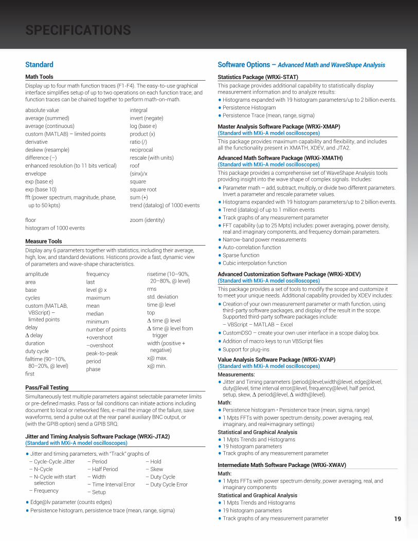
StandardMath ToolsDisplay up to four math function traces (F1-F4). The easy-to-use graphical interface simplifies setup of up to two operations on each function trace; and function traces can be chained together to perform math-on-math.
absolute value integralaverage (summed) invert (negate)average (continuous) log (base e)custom (MATLAB) – limited points product (x)derivative ratio (/)deskew (resample) reciprocaldifference (–) rescale (with units)enhanced resolution (to 11 bits vertical) roofenvelope (sinx)/xexp (base e) squareexp (base 10) square rootfft (power spectrum, magnitude, phase, sum (+) up to 50 kpts) trend (datalog) of 1000 events
floor zoom (identity)histogram of 1000 events
Measure ToolsDisplay any 6 parameters together with statistics, including their average, high, low, and standard deviations. Histicons provide a fast, dynamic view of parameters and wave-shape characteristics.
Pass/Fail TestingSimultaneously test multiple parameters against selectable parameter limits or pre-defined masks. Pass or fail conditions can initiate actions including document to local or networked files, e-mail the image of the failure, save waveforms, send a pulse out at the rear panel auxiliary BNC output, or (with the GPIB option) send a GPIB SRQ.
Jitter and Timing Analysis Software Package (WRXi-JTA2) (Standard with MXi-A model oscilloscopes)
• Jitter and timing parameters, with “Track” graphs of
• Edge@lv parameter (counts edges)
• Persistence histogram, persistence trace (mean, range, sigma)
Software Options – Advanced Math and WaveShape Analysis
Statistics Package (WRXi-STAT)This package provides additional capability to statistically display measurement information and to analyze results:
• Histograms expanded with 19 histogram parameters/up to 2 billion events.
• Persistence Histogram
• Persistence Trace (mean, range, sigma)
Master Analysis Software Package (WRXi-XMAP) (Standard with MXi-A model oscilloscopes)This package provides maximum capability and flexibility, and includes all the functionality present in XMATH, XDEV, and JTA2.
Advanced Math Software Package (WRXi-XMATH) (Standard with MXi-A model oscilloscopes)This package provides a comprehensive set of WaveShape Analysis tools providing insight into the wave shape of complex signals. Includes:
• Parameter math – add, subtract, multiply, or divide two different parameters. Invert a parameter and rescale parameter values.
• Histograms expanded with 19 histogram parameters/up to 2 billion events.
• Trend (datalog) of up to 1 million events
• Track graphs of any measurement parameter
• FFT capability (up to 25 Mpts) includes: power averaging, power density, real and imaginary components, and frequency domain parameters.
• Narrow-band power measurements
• Auto-correlation function
• Sparse function
• Cubic interpolation function
Advanced Customization Software Package (WRXi-XDEV) (Standard with MXi-A model oscilloscopes)This package provides a set of tools to modify the scope and customize it to meet your unique needs. Additional capability provided by XDEV includes:
• Creation of your own measurement parameter or math function, using third-party software packages, and display of the result in the scope. Supported third-party software packages include:
– VBScript – MATLAB – Excel
• CustomDSO – create your own user interface in a scope dialog box.
• Addition of macro keys to run VBScript files
• Support for plug-ins
Value Analysis Software Package (WRXi-XVAP) (Standard with MXi-A model oscilloscopes)Measurements:
• Jitter and Timing parameters (period@level,width@level, edge@level, duty@level, time interval error@level, frequency@level, half period, setup, skew, ∆ period@level, ∆ width@level).
Math:
• Persistence histogram • Persistence trace (mean, sigma, range)
• 1 Mpts FFTs with power spectrum density, power averaging, real, imaginary, and real+imaginary settings)
Statistical and Graphical Analysis
• 1 Mpts Trends and Histograms
• 19 histogram parameters
• Track graphs of any measurement parameter
Intermediate Math Software Package (WRXi-XWAV)Math:
• 1 Mpts FFTs with power spectrum density, power averaging, real, and imaginary components
Statistical and Graphical Analysis
• 1 Mpts Trends and Histograms
• 19 histogram parameters
• Track graphs of any measurement parameter
amplitudeareabasecyclescustom (MATLAB, VBScript) – limited pointsdelay∆ delaydurationduty cyclefalltime (90–10%, 80–20%, @ level)first
frequencylastlevel @ xmaximummeanmedianminimumnumber of points+overshoot–overshootpeak-to-peakperiodphase
risetime (10–90%, 20–80%, @ level)rmsstd. deviationtime @ leveltop∆ time @ level∆ time @ level from
triggerwidth (positive + negative)x@ max.x@ min.
– Cycle-Cycle Jitter– N-Cycle– N-Cycle with start
selection– Frequency
– Period– Half Period– Width– Time Interval Error– Setup
– Hold– Skew– Duty Cycle– Duty Cycle Error
20
SPECIFICATIONS
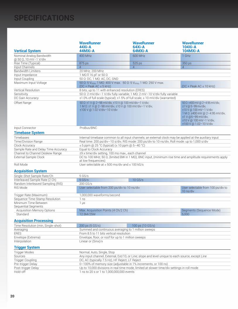
WaveRunner WaveRunner WaveRunner 44Xi-A 64Xi-A 104Xi-A Vertical System 44MXi-A 64MXi-A 104MXi-A Nominal Analog Bandwidth 400 MHz 600 MHz 1 GHz @ 50 Ω, 10 mV–1 V/divRise Time (Typical) 875 ps 525 ps 350 ps Input Channels 4 4 4 Bandwidth Limiters 20 MHz; 200 MHzInput Impedance 1 MΩ || 16 pF or 50 ΩInput Coupling 50 Ω: DC, 1 MΩ: AC, DC, GNDMaximum Input Voltage 50 Ω: 5 Vrms, 1 MΩ: 400 V max. 50 Ω: 5 Vrms, 1 MΩ: 250 V max. (DC + Peak AC ≤ 5 kHz) (DC + Peak AC ≤ 10 kHz)Vertical Resolution 8 bits; up to 11 with enhanced resolution (ERES) Sensitivity 50 Ω: 2 mV/div–1 V/div fully variable; 1 MΩ: 2 mV–10 V/div fully variableDC Gain Accuracy ±1.0% of full scale (typical); ±1.5% of full scale, ≥ 10 mV/div (warranted) Offset Range 50 Ω: ±1 V @ 2–98 mV/div, ±10 V @ 100 mV/div–1 V/div;
1 M Ω: ±1 V @ 2–98 mV/div, ±10 V @ 100 mV/div–1 V/div, ±100 V @ 1.02 V/div–10 V/div
50 Ω: ±400 mV @ 2–4.95 mV/div, ±1 V @ 5–99 mv/div, ±10 V @ 100 mV–1 V/div 1 M Ω: ±400 mV @ 2–4.95 mV/div, ±1 V @5–99 mV/div, ±10 V @ 100 mV–1 V/div, ±100 V @ 1.02–10 V/div
Input Connector ProBus/BNCTimebase SystemTimebases Internal timebase common to all input channels; an external clock may be applied at the auxiliary inputTime/Division Range Real time: 200 ps/div–10 s/div, RIS mode: 200 ps/div to 10 ns/div, Roll mode: up to 1,000 s/divClock Accuracy ≤ 5 ppm @ 25 °C (typical) (≤ 10 ppm @ 5–40 °C)Sample Rate and Delay Time Accuracy Equal to Clock AccuracyChannel to Channel Deskew Range ±9 x time/div setting, 100 ms max., each channelExternal Sample Clock DC to 100 MHz; 50 Ω, (limited BW in 1 MΩ), BNC input, (minimum rise time and amplitude requirements apply
at low frequencies)Roll Mode User selectable at ≥ 500 ms/div and ≤ 100 kS/s
Acquisition System Single-Shot Sample Rate/Ch 5 GS/s Interleaved Sample Rate (2 Ch) 5 GS/s 10 GS/s Random Interleaved Sampling (RIS) 200 GS/sRIS Mode User selectable from 200 ps/div to 10 ns/div User selectable from 100 ps/div to 10 ns/divTrigger Rate (Maximum) 1,000,000 waveforms/secondSequence Time Stamp Resolution 1 ns Minimum Time Between 1 µs Sequential Segments Acquisition Memory Options Max. Acquisition Points (4 Ch/2 Ch) Segments (Sequence Mode) Standard 12.5M/25M 5,000
Acquisition Processing Time Resolution (min, Single-shot) 200 ps (5 GS/s) 100 ps (10 GS/s) Averaging Summed and continuous averaging to 1 million sweepsERES From 8.5 to 11 bits vertical resolutionEnvelope (Extrema) Envelope, floor, or roof for up to 1 million sweepsInterpolation Linear or (Sinx)/x
Trigger SystemTrigger Modes Normal, Auto, Single, StopSources Any input channel, External, Ext/10, or Line; slope and level unique to each source, except LineTrigger Coupling DC, AC (typically 7.5 Hz), HF Reject, LF RejectPre-trigger Delay 0–100% of memory size (adjustable in 1% increments, or 100 ns)Post-trigger Delay Up to 10,000 divisions in real time mode, limited at slower time/div settings in roll modeHold-off 1 ns to 20 s or 1 to 1,000,000,000 events

21
WaveRunner WaveRunner WaveRunner 44Xi-A 64Xi-A 104Xi-A Trigger System (cont’d) 44MXi-A 64MXi-A 104MXi-AInternal Trigger Level Range ±4.1 div from center (typical)Trigger and Interpolator Jitter ≤ 3 ps rms (typical)Trigger Sensitivity with Edge Trigger 2 div @ < 400 MHz 2 div @ < 600 MHz 2 div @ < 1 GHz (Ch 1–4 + external, DC, AC, and 1 div @ < 200 MHz 1 div @ < 200 MHz 1 div @ < 200 MHz LFrej coupling)Max. Trigger Frequency with 400 MHz 600 MHz 1 GHzSMART Trigger™ (Ch 1–4 + external) @ ≥ 10 mV @ ≥ 10 mV @ ≥ 10 mV
External Trigger Range EXT/10 ±4 V; EXT ±400 mV
Basic TriggersEdge Triggers when signal meets slope (positive, negative, either, or Window) and level conditionTV-Composite Video Triggers NTSC or PAL with selectable line and field; HDTV (720p, 1080i, 1080p) with selectable frame rate
(50 or 60 Hz) and Line; or CUSTOM with selectable Fields (1–8), Lines (up to 2000), Frame Rates (25, 30, 50, or 60 Hz), Interlacing (1:1, 2:1, 4:1, 8:1)
SMART TriggersState or Edge Qualified Triggers on any input source only if a defined state or edge occurred on another input source. Delay between sources is selectable by time or eventsQualified First In Sequence acquisition mode, triggers repeatedly on event B only if a defined pattern, state, or edge (event A)
is satisfied in the first segment of the acquisition. Delay between sources is selectable by time or eventsDropout Triggers if signal drops out for longer than selected time between 1 ns and 20 s.Pattern Logic combination (AND, NAND, OR, NOR) of 5 inputs (4 channels and external trigger input). Each source can
be high, low, or don’t care. The High and Low level can be selected independently. Triggers at start or end of the pattern.
SMART Triggers with Exclusion TechnologyGlitch and Pulse Width Triggers on positive or negative glitches with widths selectable from 500 ps to 20 s or on intermittent faults
(subject to bandwidth limit of oscilloscope)Signal or Pattern Interval Triggers on intervals selectable between 1 ns and 20 sTimeout (State/Edge Qualified) Triggers on any source if a given state (or transition edge) has occurred on another source. Delay between sources is 1 ns to 20 s, or 1 to 99,999,999 eventsRunt Trigger on positive or negative runts defined by two voltage limits and two time limits. Select between
1 ns and 20 sSlew Rate Trigger on edge rates. Select limits for dV, dt, and slope. Select edge limits between 1 ns and 20 sExclusion Triggering Trigger on intermittent faults by specifying the normal width or period
Teledyne LeCroy WaveStream Fast Viewing ModeIntensity 256 Intensity Levels, 1–100% adjustable via front panel controlNumber of Channels up to 4 simultaneouslyMax Sampling Rate 5 GS/s (10 GS/s for WR 64Xi-A/64MXi-A,104Xi-A/104MXi-A in interleaved mode) Waveforms/second (continuous) Up to 20,000 waveforms/secondOperation Front panel toggle between normal real-time mode and Teledyne LeCroy WaveStream Fast Viewing mode
Automatic SetupAuto Setup Automatically sets timebase, trigger, and sensitivity to display a wide range of repetitive signalsVertical Find Scale Automatically sets the vertical sensitivity and offset for the selected channels to display a waveform
with maximum dynamic range
Probes Probes One Passive probe per channel; Optional passive and active probes availableProbe System; ProBus Automatically detects and supports a variety of compatible probesScale Factors Automatically or manually selected, depending on probe used
Color Waveform DisplayType Color 10.4” flat-panel TFT-LCD with high resolution touch screenResolution SVGA; 800 x 600 pixels; maximum external monitor output resolution of 2048 x 1536 pixelsNumber of Traces Display a maximum of 8 traces. Simultaneously display channel, zoom, memory, and math tracesGrid Styles Auto, Single, Dual, Quad, Octal, XY, Single + XY, Dual + XYWaveform Styles Sample dots joined or dots only in real-time mode
SPECIFICATIONS

22
SPECIFICATIONS
WaveRunner WaveRunner WaveRunner 44Xi-A 64Xi-A 104Xi-A Zoom Expansion Traces 44MXi-A 64MXi-A 104MXi-A Display up to 4 Zoom/Math traces with 16 bits/data point
Internal Waveform Memory M1, M2, M3, M4 Internal Waveform Memory (store full-length waveform with 16 bits/data point) or store to any number of files limited only by data storage media
Setup StorageFront Panel and Instrument Status Store to the internal hard drive, over the network, or to a USB-connected peripheral device
InterfaceRemote Control Via Windows Automation, or via Teledyne LeCroy Remote Command SetNetwork Communication Standard VXI-11 or VICP, LXI Class C CompliantGPIB Port (Accessory) Supports IEEE – 488.2Ethernet Port 10/100/1000Base-T Ethernet interface (RJ-45 connector)USB Ports 5 USB 2.0 ports (one on front of instrument) supports Windows-compatible devicesExternal Monitor Port Standard 15-pin D-Type SVGA-compatible DB-15; connect a second monitor to use -
extended desktop display mode with XGA resolution
Auxiliary Input Signal Types Selected from External Trigger or External Clock input on front panelCoupling 50 W: DC, 1 MW: AC, DC, GNDMaximum Input Voltage max. 50 W: 5 Vrms, 1 MW: 400 V max. 50 W: 5 Vrms, 1 MW: 250 V (DC + Peak AC ≤ 5 kHz) (DC + Peak AC ≤ 10 kHz)
Auxiliary OutputSignal Type Trigger Enabled, Trigger Output. Pass/Fail, or OffOutput Level TTL, ≈3.3 VConnector Type BNC, located on rear panel
GeneralAuto Calibration Ensures specified DC and timing accuracy is maintained for 1 year minimumCalibrator Output available on front panel connector provides a variety of signals for probe calibration
and compensationPower Requirements 90–264 Vrms at 50/60 Hz; 115 Vrms (±10%) at 400 Hz, Automatic AC Voltage Selection Installation Category: 300 V CAT II; Max. Power Consumption: 340 VA/340 W for all models
(both 4CH and 2CH)
EnvironmentalTemperature: Operating +5 °C to +40 °CTemperature: Non-Operating -20 °C to +60 °CHumidity: Operating Maximum relative humidity 80% for temperatures up to 31 °C decreasing linearly to 50% relative humidity at 40 °CHumidity: Non-Operating 5% to 95% RH (non-condensing) as tested per MIL-PRF-28800FAltitude: Operating Up to 3,048 m (10,000 ft.) @ ≤ 25 °CAltitude: Non-Operating Up to 12,190 m (40,000 ft.)
PhysicalDimensions (HWD) 260 mm x 340 mm x 152 mm Excluding accessories and projections (10.25” x 13.4” x 6”)Net Weight 7.26 kg. (16.0 lbs.)
Certifications CE Compliant, UL and cUL listed; Conforms to EN 61326, EN 61010-1, UL 61010-1 2nd Edition,
and CSA C22.2 No. 61010-1-04
Warranty and Service 3-year warranty; calibration recommended annually. Optional service programs include extended
warranty, upgrades, calibration, and customization services

23
ORDERING INFORMATION
Product Description Product Code
WaveRunner Xi-A Series Oscilloscopes1 GHz, 4 Ch, 5 GS/s, 12.5 Mpts/Ch WaveRunner 104Xi-A (10 GS/s, 25 Mpts/Ch in interleaved mode) with 10.4” Color Touch Screen Display600 MHz, 4 Ch, 5 GS/s, 12.5 Mpts/Ch WaveRunner 64Xi-A (10 GS/s, 25 Mpts/Ch in interleaved mode) with 10.4” Color Touch Screen Display400 MHz, 4 Ch, 5 GS/s, 12.5 Mpts/Ch WaveRunner 44Xi-A (25 Mpts/Ch in interleaved mode) with 10.4” Color Touch Screen Display
WaveRunner MXi-A Series Oscilloscopes1 GHz, 4 Ch, 5 GS/s, 12.5 Mpts/Ch WaveRunner 104MXi-A (10 GS/s, 25 Mpts/Ch in Interleaved Mode) with 10.4” Color Touch Screen Display600 MHz, 4 Ch, 5 GS/s, 12.5 Mpts/Ch WaveRunner 64MXi-A (10 GS/s, 25 Mpts/Ch in Interleaved Mode) with 10.4” Color Touch Screen Display400 MHz, 4 Ch, 5 GS/s, 12.5 Mpts/Ch WaveRunner 44MXi-A (25 Mpts/Ch in Interleaved Mode) with 10.4” Color Touch Screen Display
Included with Standard Configuration÷10, 500 MHz, 10 MW Passive Probe (Total of 1 Per Channel)Standard Ports; 10/100/1000Base-T Ethernet, USB 2.0 (5), SVGA Video out, Audio in/out, RS-232Optical 3-button Wheel Mouse – USB 2.0Protective Front CoverAccessory PouchGetting Started ManualQuick Reference GuideAnti-virus Software (Trial Version)Commercial NIST Traceable Calibration with Certificate3-year Warranty
General Purpose Software OptionsStatistics Software Package WRXi-STATMaster Analysis Software Package WRXi-XMAP (Standard with MXi-A model oscilloscopes) Advanced Math Software Package WRXi-XMATH (Standard with MXi-A model oscilloscopes) Intermediate Math Software Package WRXi-XWAV (Standard with MXi-A model oscilloscopes)Value Analysis Software Package (Includes XWAV and JTA2) WRXi-XVAP (Standard with MXi-A model oscilloscopes) Advanced Customization Software Package WRXi-XDEV (Standard with MXi-A model oscilloscopes)Spectrum Analyzer and Advanced FFT Option WRXi-SPECTRUMProcessing Web Editor Software Package WRXi-XWEB
Application Specific Software OptionsJitter and Timing Analysis Software Package WRXi-JTA2 (Standard with MXi-A model oscilloscopes)Digital Filter Software Package WRXi-DFP2Disk Drive Measurement Software Package WRXi-DDM2Power Analysis Software Package WRXi-PWRSerial Data Mask Software Package WRXi-SDM
Product Description Product Code
Application Specific Software Options (cont’d)QualiPHY Enabled Ethernet Software Option QPHY-ENET*QualiPHY Enabled USB 2.0 Software Option QPHY-USB†
QualiPHY Enabled MOST150 Software Option QPHY-MOST150QualiPHY Enabled MOST50 Software Option QPHY-MOST50QualiPHY Enabled BroadR-Reach Software Option QPHY-BroadR-Reach*EMC Pulse Parameter Software Package WRXi-EMCElectrical Telecom Mask Test Package ET-PMT
* TF-ENET-B required. †TF-USB-B required.
Serial Data OptionsI2C Trigger and Decode Option WRXi-I2Cbus TDSPI Trigger and Decode Option WRXi-SPIbus TDUART and RS-232 Trigger and Decode Option WRXi-UART-RS232bus TDLIN Trigger and Decode Option WRXi-LINbus TDCANbus TD Trigger and Decode Option CANbus TDCANbus TDM Trigger, Decode, and Measure/Graph Option CANbus TDMFlexRay Trigger and Decode Option WRXi-FlexRaybus TDFlexRay Trigger and Decode Physical Layer WRXi-FlexRaybus TDP Test OptionVehicle Bus Analyzer Package - includes CANbus TDM, WRXi-VBA FlexRay TDP, LINBus TD, and ProtoBus MAG Audiobus Trigger and Decode Option WRXi-Audiobus TD for I2S, LJ, RJ, and TDMAudiobus Trigger, Decode, and Graph Option WRXi-Audiobus TDG for I2S LJ, RJ, and TDM MIL-STD-1553 Trigger and Decode Option WRXi-1553 TDUSB2-HSIC Decode Option WRXi-USB2-HSICbus D
A variety of Vehicle Bus Analyzers based on the WaveRunner Xi-A platform are available. These units are equipped with a Symbolic CAN trigger and decode.
Mixed Signal Oscilloscope Options500 MHz, 18 Ch, 2 GS/s, 50 Mpts/Ch MS-500 Mixed Signal Oscilloscope Option250 MHz, 36 Ch, 1 GS/s, 25 Mpts/Ch MS-500-36 (500 MHz, 18 Ch, 2 GS/s, 50 Mpts/Ch Interleaved) Mixed Signal Oscilloscope Option250 MHz, 18 Ch, 1 GS/s, 10 Mpts/Ch MS-250 Mixed Signal Oscilloscope Option
Probes and Amplifiers*Set of 4 ZS1500, 1.5 GHz, 0.9 pF, 1 MW ZS1500-QUADPAK High Impedance Active Probe Set of 4 ZS1000, 1 GHz, 0.9 pF, 1 MW ZS1000-QUADPAK High Impedance Active Probe 500 MHz Active Differential Probe (x10, ÷1, ÷10, ÷100) AP03330 A; 100 MHz Current Probe – AC/DC; 30 Arms; 50 Arms Pulse CP03130 A; 50 MHz Current Probe – AC/DC; 30 Arms; 50 Arms Pulse CP03030 A; 50 MHz Current Probe – AC/DC; 30 Arms; 50 Apeak Pulse AP015150 A; 10 MHz Current Probe – AC/DC; 150 Arms; 500 Apeak Pulse CP150500 A; 2 MHz Current Probe – AC/DC; 500 Arms; 700 Apeak Pulse CP5001,400 V, 100 MHz High-Voltage Differential Probe ADP3051,400 V, 20 MHz High-Voltage Differential Probe ADP3001 Ch, 100 MHz Differential Amplifier DA1855A
* A wide variety of other passive, active, and differential probes are also available. Consult Teledyne LeCroy for more information.

ORDERING INFORMATIONProduct Description Product Code
Hardware Accessories* 10/100/1000Base-T Compliance Test Fixture TF-ENET-B†
USB 2.0 Compliance Test Fixture TF-USB-BExternal USB2 to GPIB Adaptor USB2-GPIBSoft Carrying Case WRXi-SOFTCASEHard Transit Case WRXi-HARDCASEMounting Stand – Desktop Clamp Style WRXi-MS-CLAMPRackmount Kit WRXi-RACKMini Keyboard WRXi-KYBDRemovable Hard Drive Package (Includes removeable WRXi-A-RHD hard drive kit and two hard drives)Additional Removable Hard Drive WRXi-A-RHD-02
* A variety of local language front panel overlays are also available.† Includes ENET-2CAB-SMA018 and ENET-2ADA-BNCSMA.
Customer ServiceTeledyne LeCroy oscilloscopes and probes are designed, built, and tested to ensure high reliability. In the unlikely event you experience difficulties, our digital oscilloscopes are fully warranted for three years, and our probes are warranted for one year.
This warranty includes: • No charge for return shipping • Long-term 7-year support • Upgrade to latest software at no charge
Local sales offices are located throughout the world. Visit our website to find the most convenient location.
© 2009 by Teledyne LeCroy, Inc. All rights reserved. Specifications, prices, availability, and delivery subject to change without notice. Product or brand names are trademarks or requested trademarks of their respective holders.
1-800-5-LeCroy teledynelecroy.com
WRXi-ADS-16jan14


