Indications for use:The WayPoint™ Stereotactic System is intended to be used with commercially available stereotactic systems for neurosurgical procedures which require the accurate positioning of microelectrodes, stimulating electrodes, or other instruments in the brain or nervous system.
Intended use:The WayPoint Anchor/Locator System is intended for use by neurosurgeons in a clinical or standard operating room environment to implant fiducial anchors used to plan patient specific microTargeting stereotactic platform used in neurosurgical procedures.
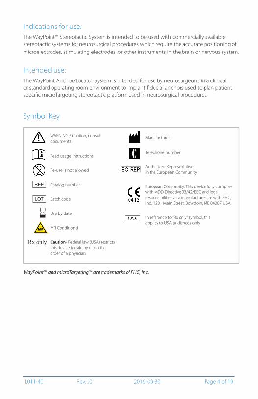
Symbol Key
WARNING / Caution, consult documents
Read usage instructions
Re-use is not allowed
Catalog number
Batch code
Use by date
MR Conditional
Caution- Federal law (USA) restricts this device to sale by or on the order of a physician.
Manufacturer
Telephone number
Authorized Representative in the European Community
European Conformity. This device fully complies with MDD Directive 93/42/EEC and legal responsibilities as a manufacturer are with FHC, Inc., 1201 Main Street, Bowdoin, ME 04287 USA.
In reference to “Rx only” symbol; this applies to USA audiences only
Rx only
j
l
f
WayPoint™ and microTargeting™ are trademarks of FHC, Inc.
L011-40 Rev. J0 2016-09-30 Page 5 of 10
WARNING: Do not drill or install anchors in bone that is less than 4.5mm thick, or in bone that is weakened or diseased.
WARNING: Do not use anchors that exhibit any sign of looseness. Replace anchors and rescan if necessary.
WARNING: A WayPoint Locator Pin must be screwed in to the depth of its built in stop to provide accurate registration.
WARNING: WayPoint Locator pins may come in contact with non-sterile items during scanning procedures. Wipe locator pins and the area around the wounds with antiseptic before the locator pin is removed.
WARNING: Do not allow WayPoint Anchors to remain implanted for more than 28 days.
CAUTION: For the most secure fit of the WayPoint Anchors, advance drill and driver tools as perpendicular to the skull as possible, and do not permit them to ‘wobble’ during advancement.
CAUTION: Avoid over tightening anchors and pins, as this can strip bone, shear an anchor, or otherwise damage components.
CAUTION: Instruct the patient to avoid situations that could affect or disrupt the implanted anchors and to be cautious about infection.
CAUTION: Federal law (USA) restricts this device to sale by or on the order of a physician.Rx only
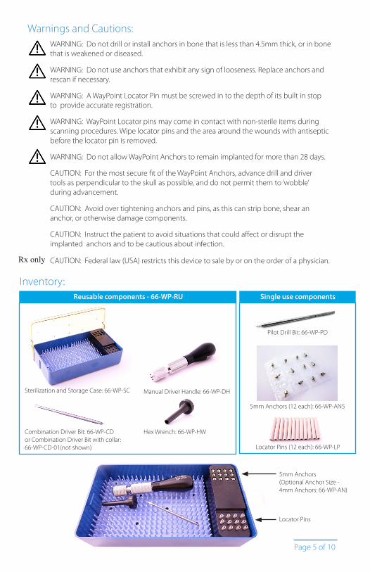
Inventory:
Sterilization and Storage Case: 66-WP-SC
5mm Anchors (12 each): 66-WP-AN5
Locator Pins (12 each): 66-WP-LP
Manual Driver Handle: 66-WP-DH
Combination Driver Bit: 66-WP-CDor Combination Driver Bit with collar: 66-WP-CD-01(not shown)
Tools must be thoroughly cleaned, using a disinfectant solution, and then wiped with adistilled water dampened cloth after each use, prior to re-sterilization.
WayPoint Anchors, Pins, and Pilot Drill Bit are single use items and must be disposed of appropriately after use.
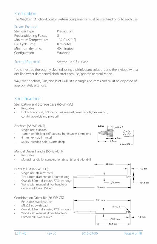
Specifications:Sterilization and Storage Case (66-WP-SC)• Re-usable• Holds 12 anchors, 12 locator pins, manual driver handle, hex wrench,
combination bit and pilot drill
Anchors (66-WP-AN5)• Single-use, titanium• 1.5mm self-drilling, self-tapping bone screw, 5mm long• 4 mm hex nut, 4 mm tall• M3x.5 threaded hole, 3.2mm deep
Manual Driver Handle (66-WP-DH)• Re-usable• Manual handle for combination driver bit and pilot drill
Pilot Drill Bit (66-WP-PD)• Single-use, stainless steel• Tip: 1.1mm diameter drill, 4.0mm long• Overall: 3.2mm diameter, 77.3mm long • Works with manual driver handle or
Osteomed Power Driver
Combination Driver Bit (66-WP-CD)• Re-usable, stainless steel• M3x0.5 screw thread • Overall: 3.2mm diameter, 77.3mm long • Works with manual driver handle or
Osteomed Power Driver
L011-40 Rev. J0 2016-09-30 Page 7 of 10
Illustrative Procedure:
Follow aseptic technique throughout. The implant procedure does not need to be done in an OR setting.
Additionally, refer to the Fiducial Placement Template DFU (L011-40-05) for information on how to position anchors around approximate entry point locations.
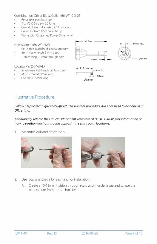
1. Assemble drill and driver tools.
2. Use local anesthesia for each anchor installation:
A. Create a 10-15mm incision through scalp and muscle tissue and scrape the pericranium from the anchor site.
Combination Driver Bit w/Collar (66-WP-CD-01)• Re-usable, stainless steel• Tip: M3x0.5 screw, 3.3 long• Overall: 3.2mm diameter, 77.3mm long• Collar: 45.1mm from collar to tip • Works with Osteomed Power Driver only
Hex Wrench (66-WP-HW) • Re-usable, Black hard-coat aluminum• 4mm hex wrench, ? mm deep• 1.7mm long, 3.3mm through hole
Locator Pin (66-WP-LP)• Single-use, PEEK and stainless steel• M3x05 thread, 3mm long• Overall: 21.5mm long
L011-40 Rev. J0 2016-09-30 Page 8 of 10
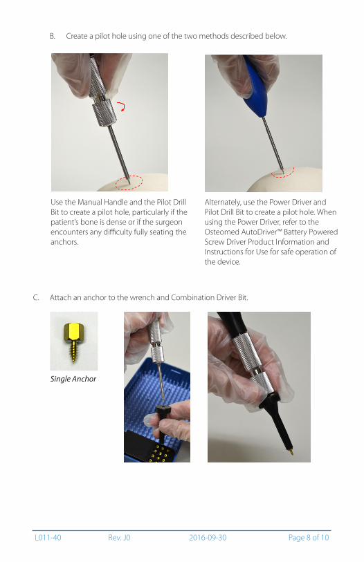
Alternately, use the Power Driver and Pilot Drill Bit to create a pilot hole. When using the Power Driver, refer to the Osteomed AutoDriver™ Battery Powered Screw Driver Product Information and Instructions for Use for safe operation of the device.
Use the Manual Handle and the Pilot Drill Bit to create a pilot hole, particularly if the patient’s bone is dense or if the surgeon encounters any difficulty fully seating the anchors.
B. Create a pilot hole using one of the two methods described below.
C. Attach an anchor to the wrench and Combination Driver Bit.
Single Anchor
L011-40 Rev. J0 2016-09-30 Page 9 of 10
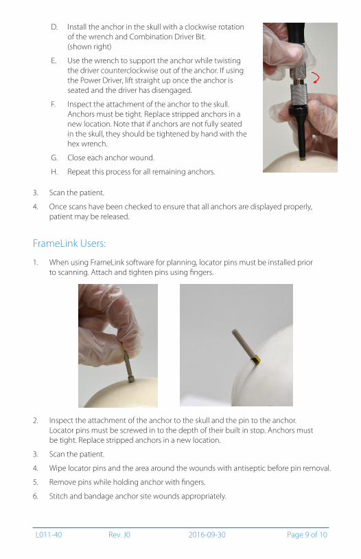
B. Create a pilot hole using one of the two methods described below.D. Install the anchor in the skull with a clockwise rotation
of the wrench and Combination Driver Bit. (shown right)
E. Use the wrench to support the anchor while twisting the driver counterclockwise out of the anchor. If using the Power Driver, lift straight up once the anchor is seated and the driver has disengaged.
F. Inspect the attachment of the anchor to the skull. Anchors must be tight. Replace stripped anchors in a new location. Note that if anchors are not fully seated in the skull, they should be tightened by hand with the hex wrench.
G. Close each anchor wound.
H. Repeat this process for all remaining anchors.
3. Scan the patient.
4. Once scans have been checked to ensure that all anchors are displayed properly, patient may be released.
FrameLink Users:
1. When using FrameLink software for planning, locator pins must be installed prior to scanning. Attach and tighten pins using fingers.
2. Inspect the attachment of the anchor to the skull and the pin to the anchor. Locator pins must be screwed in to the depth of their built in stop. Anchors must be tight. Replace stripped anchors in a new location.
3. Scan the patient.
4. Wipe locator pins and the area around the wounds with antiseptic before pin removal.
5. Remove pins while holding anchor with fingers.
6. Stitch and bandage anchor site wounds appropriately.
L011-40 Rev. J0 2016-09-30 Page 10 of 10
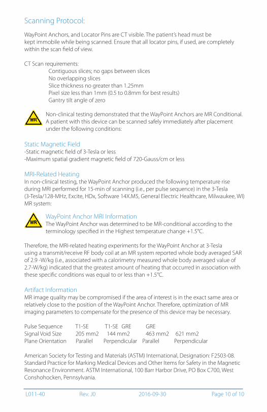
Scanning Protocol:
WayPoint Anchors, and Locator Pins are CT visible. The patient’s head must be kept immobile while being scanned. Ensure that all locator pins, if used, are completely within the scan field of view.
CT Scan requirements: Contiguous slices; no gaps between slices No overlapping slices Slice thickness no greater than 1.25mm Pixel size less than 1mm (0.5 to 0.8mm for best results) Gantry tilt angle of zero
Non-clinical testing demonstrated that the WayPoint Anchors are MR Conditional. A patient with this device can be scanned safely immediately after placement under the following conditions:
Static Magnetic Field-Static magnetic field of 3-Tesla or less-Maximum spatial gradient magnetic field of 720-Gauss/cm or less
MRI-Related HeatingIn non-clinical testing, the WayPoint Anchor produced the following temperature rise during MRI performed for 15-min of scanning (i.e., per pulse sequence) in the 3-Tesla (3-Tesla/128-MHz, Excite, HDx, Software 14X.M5, General Electric Healthcare, Milwaukee, WI) MR system:
Therefore, the MRI-related heating experiments for the WayPoint Anchor at 3-Tesla using a transmit/receive RF body coil at an MR system reported whole body averaged SAR of 2.9 -W/kg (i.e., associated with a calorimetry measured whole body averaged value of 2.7-W/kg) indicated that the greatest amount of heating that occurred in association with these specific conditions was equal to or less than +1.5°C.
Artifact InformationMR image quality may be compromised if the area of interest is in the exact same area or relatively close to the position of the WayPoint Anchor. Therefore, optimization of MR imaging parameters to compensate for the presence of this device may be necessary.
American Society for Testing and Materials (ASTM) International, Designation: F2503-08. Standard Practice for Marking Medical Devices and Other Items for Safety in the Magnetic Resonance Environment. ASTM International, 100 Barr Harbor Drive, PO Box C700, West Conshohocken, Pennsylvania.
WayPoint Anchor MRI InformationThe WayPoint Anchor was determined to be MR-conditional according to the terminology specified in the Highest temperature change +1.5°C.