42
WBSn-2400 User Guide Page - 1 - WBSn-2400 User Guide September 2011 Version 1.0

WBSn-2400 User Guide Page - 1 -
WBSn-2400 User Guide
September 2011
Version 1.0

WBSn-2400 User Guide Page - 2 -
Contents INTRODUCTION .........................................................................................- 4 -
System Components.............................................................................................................. - 5 -
INSTALLATION ...........................................................................................- 6 -
WBSn-2400 Pre-Installation Checklist ................................................................................. - 6 -
Installation and Set-up ....................................................................................................... - 11 - Installing the WBSn-2400 base station .................................................................................... - 11 - Wind Loading Considerations ................................................................................................. - 12 - Connecting Power and DATA .................................................................................................. - 12 -
Accessing the Wavion Management Interface.................................................................... - 13 -
Automatic Channel Selection screen ................................................................................... - 14 -
DEFINING AND MANAGING WBSN ...........................................................- 15 -
Status .................................................................................................................................. - 15 - Checking System Setup ......................................................................................................... - 15 -
Configuration ...................................................................................................................... - 16 - System Setup ....................................................................................................................... - 16 - Wireless Interface -- Setting up WLANs ................................................................................... - 18 - Radio Configuration .............................................................................................................. - 23 - ACS (Online, Offline) ............................................................................................................. - 23 -
Network/Ethernet Interface – Setting up WLANs .............................................................. - 24 -
Administration ..................................................................................................................... - 27 - Management ........................................................................................................................ - 27 - Users .................................................................................................................................. - 28 - Firmware ............................................................................................................................. - 28 - Diagnostics .......................................................................................................................... - 31 - Configuration files ................................................................................................................. - 32 - Log ..................................................................................................................................... - 32 -
APPENDIX A: TROUBLESHOOTING ...........................................................- 33 -
APPENDIX B: FREQUENTLY ASKED QUESTIONS .......................................- 34 -
APPENDIX C: HARDWARE SPECIFICATION ..............................................- 37 -
APPENDIX D: SPECIFICATIONS AND PATTERNS ......................................- 38 -
GLOSSARY ................................................................................................- 41 -

WBSn-2400 User Guide Page - 3 -
FCC Notice to Users and Operators
This equipment has been tested and found to comply with the limits for a Class B digital device, pursuant to Part 15 of the FCC Rules. These limits are designed to provide reasonable protection against harmful interference when the equipment is operated in a commercial environment. This equipment generates, uses, and can radiate radio frequency energy and, if not installed and used in accordance with the instruction manual, may cause harmful interference to radio communications. Operation of this equipment in a residential area is likely to cause harmful interference, in which case the user will be required to correct the interference at his own expense. If this equipment does cause interference to radio or television reception, which can be determined by turning the equipment off and on, the user is encouraged to correct the interference by using one of the following measures:
• Reorient or relocate the receiving antenna.
• Increase separation between the equipment and receiver.
• Connect the equipment to an outlet on a circuit different from that to which the receiver is connected.
• Consult the dealer or an experienced radio/TV technician.
Changes or modifications to this unit not expressly approved by the party responsible for compliance could void the user’s authority to operate the equipment.
Note: This device complies with part 15 of the FCC Rules. Operation is subject to the following two conditions: (1) This device may not cause harmful interference, and (2) this device must accept any interference received, including interference that may cause undesired operation.
R&TTE Compliance Statement
This equipment (ETSI-models only) complies with all the requirements of DIRECTIVE 1999/5/CE OF THE EUROPEAN PARLIAMENT AND THE COUNCIL of March 9, 1999 on radio equipment and telecommunication terminal Equipment and the mutual recognition of their conformity (R&TTE).
Note: Wavion and its resellers or distributors are not liable for injury, damage or regulation violations associated with the installation of outdoor units or antennas.
Copyright © Wavion Wireless Networks 2011

WBSn-2400 User Guide Page - 4 -
Introduction WBSn base stations combine Wavion’s true two-way Beamforming and interference immunity technologies together with 802.11n 3x3:3 MIMO, and deliver best capacity and coverage, with speeds of up to 450 Mbps. The spatially adaptive Beamforming signals travel in different propagation paths, and are coherently combined at the receiver’s antenna, leveraging a unique High Gain Diversity Polarized (HGDP) antenna array for maximum performance.
Utilizing a decade of outdoor Wi-Fi experience, Wavion’s Interference Immunity Suite includes:
• Beamforming, with its inherent ability to suppress interference • The Dynamic Interference Handling (DIH) algorithm, that continuously optimizes receiver’s
parameters according to varying noise levels • The Automatic Channel Selection (ACS) algorithm, that automatically online identifies, selects and
utilizes the best operating channel selection • The Wavion Rate Adaptation (WARA) which enables optimal rate selection in outdoor environments
with high interference • Down Tilted Antenna (DTA) and sector antenna abilities to reject noise out of their fields-of-view
WBSn base stations are carrier grade, ruggedized IP-68 rated units, designed to provide the highest reliability, quality of service, security and manageability. WBSn base stations come with a complete set of FCAPS management tools.
WBSn base stations support 802.11n with three spatial data streams, for transmitting at speeds of up to 450 Mbps. The Beamforming and the HGDP antenna array increase coverage by up to 50%, and enable NLOS connectivity and indoor signal penetration.
WBSn base stations comprising rich embedded networking capabilities, including Routing and a fully integrated Access Controller, for flexible service planning and reduced costs.
WBSn is designed to be environmentally-friendly with low power consumption, fewer sites to power, aesthetic smart design, and green standard compliance.
With fewer sites required per covered area, highest network reliability and enhanced service options, WBSn provides up to 50% savings of CAPEX and OPEX and the fastest ROI.
WBSn-2400 Key Benefits:
• Exceptional coverage, range, throughput, network capacity, scalability, and reliability
• Excellent building penetration • Uniform coverage and enhanced non-line-of-
sight operation • High interference resilience • Enhanced mobility support • Simple deployment and low infrastructure and
operating costs • Full compatibility with standard 802.11 b/g/n
clients
Important Note:
Wavion base stations are comprised of highly advanced technical equipment. Only experienced installation professionals who are familiar with local building and safety codes, and other relevant regulations, and wherever applicable are licensed by the appropriate government regulatory authorities, should install Wavion equipment. Failure to comply with this may void the WBSn family of products warranty and may consequently expose the end user or Service Provider to legal and financial liabilities.

WBSn-2400 User Guide Page - 5 -
System Components The WBSn-2400 system utilizes hardware components, as described in the below table.
Component Description
Product Number An internal ID that identifies the components of the system. There are no field replaceable units. This information can be used to identify the hardware components.
Serial Number An internal ID that identifies the date of manufacture, production lot, and individual component. There are no field replaceable units. With the serial number, this information is used to identify a specific unit.
Antenna Type Indicates the default antenna type installed in the unit. Although WBSn-2400 antennas are detachable, they are an integral element of the WBSn-2400 unit. The Beamforming capability encompasses the specific attributes of the antennas. Important note: Antennas should never be replaced without official guidance and instruction from a Wavion Technical Support person.

WBSn-2400 User Guide Page - 6 -
Installation This document is intended to help you set up and configure your WBSn-2400 base station. Unless specified otherwise, the use of the product name WBSn-2400 refers to all WBSn-2400 base stations.
WBSn-2400 Pre-Installation Checklist The following checklist covers all the procedures and equipment that you need to acquire and assemble, prior to beginning the installation and configuration procedures. Ensure that you check this list carefully, before beginning any of the procedures described later in this Guide.
Check contents of package
WBSn-2400-O WBSn-2400-O base station unit (Omni) PoE injector unit 3 antennas Post-clamp Two steel bands 2 screws, each with attached spring and flat washers Iron security cable Waterproof sealing tape for IP68 (band to sealing rubber) Plastic cap and cap cover
WBSn-2400-S WBSn-2400-S unit (Sector) PoE injector unit Post-clamp Two steel bands 2 screws, each with attached spring and flat washers Iron security cable Plastic cap and cap cover
Warning
The WBSn-2400 should only be installed using the antennas provided as part of the original package. Ensure that the USB port on the base station unit is properly sealed.
Additional equipment and tools required for installation
• Ethernet cable (outdoor CAT5e 4-pair data cable, with RJ45 connectors) Note: Maximum cable length -- 100 meters
• Ground cable • Portable PC • Lightning protection • 1”-6” diameter pole (on which to mount the unit)

WBSn-2400 User Guide Page - 7 -
Ensure a safe and secure environment
Warning
Connect the PoE injector to the unit using only a straight Ethernet cable.
Do not use crossed cables between the PoE injector and the unit!
Follow these guidelines to ensure safe operation of the WBSn-2400 base station:
• Do not touch or move the antennas while the unit is switched on. • Make sure the antennas are connected when operating the radio or attempting
to transmit data, otherwise, the radio may be damaged. • Do not hold the antenna close to or touching any exposed parts of the body,
especially the face or eyes, while transmitting. • The use of wireless devices on airplanes is governed by the Federal Aviation
Administration (FAA). (US only) • The use of wireless devices in hazardous locations is limited to the constraints
posed by the safety directors of such environments. • The use of wireless devices in hospitals is restricted to the limits set forth by
each hospital. • Do not operate a portable transmitter near unshielded blasting caps or in an
explosive environment. • The Wavion WBSn-2400 must be used only with Wavion-approved components
and antennas.
Note:
The Federal Communications Commission (FCC) with its action in ET Docket 96-8 has adopted a safety standard for human exposure to RF electromagnetic energy emitted by FCC certified equipment. Proper operation of the Wavion WBSn-2400 according to the instructions found in this manual, results in user exposure that is substantially below the FCC recommended limits.
To ensure optimal performance, select the location for the equipment using the following guidelines:
• The antenna should be directed towards the area intended to be covered, with maximum possible lines of sight for client locations. Generally speaking, the higher the placement of the antenna, the better the link quality achievable. For WBSn-2400-S, the coverage zone is 120° wide.
• The location of the unit should enable easy access for installation and testing. • When installing in locations where other devices exist that operate in the same frequency range,
ensure that recommended distances are adhered to. • The ideal height at which a base station should be installed is 3 meters above the rooftops of the
buildings within the coverage zone. • The omni-directional unit should be installed at the highest point of a metal pole. This is to ensure
that there is no interference caused by the close proximity of the unit to the metal. Where this is not possible, the unit should be kept at least 1 meter from the metal pole.
• Keeping the maximum distance possible from an RF radiating source is recommended.

WBSn-2400 User Guide Page - 8 -
Preparing the installation site
Only experienced installation professionals who are familiar with local building and safety codes and are licensed, wherever applicable, by the appropriate government regulatory authorities, should install outdoor units and antennas.
Warnings
Do not modify the construction of this product. Modifying the operating frequency or enhancing the transmit output power through the use of external amplifiers or other equipment is illegal.
This device is for outdoor or indoor use on the condition that operation of this device causes no harmful interference to authorized radio stations. This device shall not influence aircraft security and/or interfere with legal communications. If this device is found to cause interference, the operator of this equipment shall cease operating this device immediately.
How to prepare the site:
• Ascertain the existence of potential posts or poles to which a base station could be attached. Consider the axis of the post, its placement, and whether extenders are required.
• Follow the appropriate electrical and building codes to ensure safe and durable wiring.
• The length of the Ethernet cable connecting the unit to the network device (PC, switch, router, and so on) should not exceed 100 meters. There is no limitation on the length of the cable connecting the PoE to the unit, as long as the combined length of the cables connecting the network device to the PoE and the PoE to the unit does not exceed 100 meters.
Grounding best practices, using a data protection device
1. Position the protection device as close to the building entrance as possible.
2. Attach a 10 AWG grounding cable to the ground point on the data protection device.
3. Attach the other end of the grounding cable to the grounding bar of the building.
Lightning Surge Protector Connection Diagram

WBSn-2400 User Guide Page - 9 -
Connecting Antennas (for WBSn-2400-O only)
Note: The antennas should only be connected once the installation procedure has been successfully completed.
How to connect the antennas:
Screw each of the three antennas into the three N-type connectors on the WBSn-2400 base station unit.
Warnings
In order for the WBSn-2400-O to work properly, all three antennas must be connected.
Only connect the unit to the power supply once all the antennas are connected.
Use caution when connecting the antennas. Undue haste can damage the unit.
Do not screw in the antenna when holding its top section, or you may damage the antenna.
Antenna Sealing
The following procedure describes how to correctly seal the antennas against moisture.
Caution
• It is important to carefully read this procedure and perform all the steps, to ensure maximal moisture protection.
• Use high quality sealing material to ensure IP-68 compliant protection against dust and water.
How to seal the antennas:
1. After the antenna is connected, use the supplied isolation tape to cover the N-Type connectors and the lower part of the antennas.
2. Cut 18 cm of the attached splicing tape. 3. Stretch and wrap the tape in an even, half overlapping manner around the
antenna and N-Type connector. Cover this with a layer of vinyl plastic tape.
WBSn-2400 User Guide Page - 10 -
Safety instructions and information
Please ensure that you read and understand the following safety information. Ensure that you carefully read and follow all instructions in this manual, and heed all warnings.
Warnings
It is illegal to modify the construction of this product. Modifying the operating frequency or enhancing the transmit output power through the use of external amplifiers or other equipment is specifically disallowed by the "Telecommunications Act.
There is a risk of personal injury or death if the WBSn-2400 antennas are close to electric power lines.
By nature of the outdoor installation, you may be exposed to hazardous environments and high voltage. Use extreme caution when installing the system.
All servicing should be referred to qualified service personnel only. There are no user-serviceable parts inside. Servicing is required when the apparatus has been damaged in any way.
This apparatus must be properly grounded.
Do not open the unit – risk of electric shock.
Any change or modification not expressly described in this manual or approved by the manufacturer could void your authority to operate this equipment.
The WBSn-2400 should only be installed using the antennas that were provided as part of the original package.
A minimum distance of 40cm should be kept from the WBSn-2400 antenna when the system is in operation.
Only UL-listed parts and components should be used for installation.
To maintain Overvoltage (Installation) Category II, install a suitable surge suppressor device in the branch circuit to limit expected transients to Overvoltage Category II values. The limits are based on IEC60664 and are also located in Table 2H of UL60950 (for mains 110V, the transient rating is 1500V).

WBSn-2400 User Guide Page - 11 -
Installation and Set-up The following section describes the installation and configuration procedures for the WBSn-2400 base station.
Installing the WBSn-2400 base station Prior to performing the procedures described in this section, ensure that you have read all the information, and followed all instructions and safety precautions in the Pre-Installation Checklist.
To install WBSn-2400: 1. Decide the manner in which the post-clamp will be attached to the post, whether horizontally or
vertically. Note: If you wish to install WBSn-2400 on a horizontal plane, you need to include special extenders in your order. Example: Horizontal post-clamp
2. Slide the steel bands into the appropriate side slots of the post clamp.
Note: For a thinner post, the steel bands should be threaded through the inner slots, and for a wider post, through the outer slots.
3. Attach the post-clamp to the post, and close and tighten the steel bands. 4. If you are installing the WBSn-2400 on a vertical post, attach the WBSn-2400 unit to the post-clamp,
with the screws and washers. Tighten the screws using a ratchet key, set at 13 mm, and proceed to Step 6.
5. If you are installing WBSn-2400 on a horizontal post, select the direction in which the base station unit should point on the horizontal plane prior to continuing with the installation. Once you have determined the correct direction, connect the two extenders to the post clamp. Note: The extenders must be specified as an extra item when ordering the WBSn-2400 unit.
6. Attach the WBSn-2400 base station unit and connected extenders to the base station unit.

WBSn-2400 User Guide Page - 12 -
WBSn attached with extenders
7. As you tighten the screws, verify that the tilt and direction of the base station unit are correct for the
coverage area required. Note: In an urban setting, with a high-placed installation, a slight downwards tilt (approximately 8-10 degrees) will help reduce noise and interference.
8. For extra security, thread the iron cable through the corner hole on the post-clamp, and the middle hole on the WBSn-2400 unit, securing it with the Caribena provided. Note: This will provide extra physical security for the WBSn-2400 unit.
Wind Loading Considerations The Wavion WBSn-2400 weighs approximately eight kilograms, including all mounting hardware. When the Wavion WBSn-2400 is mounted on a pole, the sail area of the WBSn-2400 is approximately 0.11 m2. The Wavion WBSn-2400 can load a pole with a maximum load of 3400 Newton in wind conditions of 264 km/h (165 mph).
You should evaluate the static and dynamic load bearing capabilities for each assembly and installation individually.
Connecting Power and DATA The following describes how to apply power and data to the WBSn-2400 .
Prior to connecting power to the WBSn-2400, ensure that you have read and performed all instructions in the pre-installation checklist.
The Wavion WBSn-2400 is equipped with two ports.
• Use the ETH port to connect the PoE cable.
• The USB port is for engineering purposes only. Ensure that the USB port is properly sealed with a plastic cap.
Please also note the following:
Warnings
You must always install an external grounding wire. Make sure you have completed grounding before you connect power to the WBSn-2400 unit.
This is not a mid-span powered device. Do not attempt to daisy-chain PoE devices.
Note: National Electrical Codes (NEC) Article 800 requires the use of an Agency Listed (UL/CSA) Building Entrance Protector for all power and communications cables entering a building. Article 800 is intended to protect the building and occupants from fires caused by transient voltage and current surges.

WBSn-2400 User Guide Page - 13 -
To connect to the data port:
1. Connect a grounding cable to the grounding terminal and tighten the grounding screw firmly. See Grounding the Data protection device for a connection diagram.
2. Connect the other end of the cable to the nearest grounded metallic body. 3. Ensure that the power is turned off for the designated circuits. 4. Unscrew the plastic cap and the cap cover from the Wavion WBSn-2400. 5. Run a shielded Category 5 Ethernet cable (appropriate for outdoor use) through the cap.
Warning! Ensure that no network cable is plugged into the IN port of the PoE injector. 6. Connect one end of the Category 5 cable to the OUT port of the Wavion PoE injector. 7. Connect the other end of the Category 5 Ethernet cable to the ETH port on the Wavion WBSn-2400.
Note: Use a shielded RJ45 8-pin modular plug to terminate the cables at the required length. 8. Close and firmly tighten the plastic cap, to ensure perfect sealing and IP-68 compliance. Connect the
network cable to the IN port of the PoE injector.
Note: The above procedure must be conducted after every disconnection of the Ethernet cable from either ETH port on the WBSn-2400 unit or from the OUT port of the POE injector.
POE port RJ45 Pin Descriptions
Pin Signal Color Description
1 BI_DA+ Orange-White Bi-directional pair A +, POE GND
2 BI_DA- Orange Bi-directional pair A -, POE GND
3 BI_DB+ Green-White Bi-directional pair B +, POE +55V
4 BI_DC+ Blue Bi-directional pair C +, POE +55V
5 BI_DC- Blue-White Bi-directional pair C -, POE +55V
6 BI_DB- Green Bi-directional pair B -, POE +55V
7 BI_DD+ Brown-White Bi-directional pair D +, POE GND
8 BI_DD- Brown Bi-directional pair D -, POE GND
Accessing the Wavion Management Interface The following procedure describes how to log in to the WBSn-2400 Wavion Management Interface, and from there enter the Set-up Wizard, and further configuration information.
1. In an internet browser, enter the Management IP address of the WBSn unit in the URL navigation field. Note: The default IP address of the unit is IP: http://192.168.1.1. Currently, Microsoft Internet Explorer, Chrome and Mozilla Firefox browsers are supported.
2. A log-in screen is displayed. a. Enter admin in the User Name field. b. Enter admin in the password field. c. Specify the language in which you wish to work. (This field will be functional in a future release.)
3. Click Connect. The Wavion EMS screen is displayed. 4. Select the Setup Wizard option. 5. The Installation screen is displayed. Click the arrow in the bottom right corner of the screen to
proceed to the Network Configuration screen.

WBSn-2400 User Guide Page - 14 -
6. Complete the parameters, to set up your initial networking configuration.
Note: Further configuration parameters are available, and should be specified in order to complete your set-up. For more information, see Further Configuration Features.
Parameter Description and value
Network mode Bridge
IP address The current IP address of the unit
Mask The current subnet mask used to establish the broadcast domain. The default mask of the unit is 255.255.255.0.
Gateway The current IP address of the default gateway.
IP Method Select Manual or DHCP
VAP Name The default VAP name string
Security mode Specify the required Wi-Fi security protocol for the VAP
Password Specify a unique password for the Wi-Fi security
Automatic Channel Selection screen The Automatic Channel Selection utilizes an embedded algorithm to scan for the best channel with which your base station can work, ensuring optimal capacity, minimal interference and maximum performance. 1. Click Press to start ACS scan. The scan begins, and a progress indicator is displayed, showing the
percentage of completion. When the scan is complete, (after approximately five minutes), the button label changes to ACS done. The ACS results are presented on the screen, showing a bar graph with the quality of each channel presented by the height of the bar.
2. You are requested to exit the Setup Wizard, by clicking Exit.

WBSn-2400 User Guide Page - 15 -
Defining and Managing WBSn The WBSn interface is comprised of three separate sections, that each relate to the key areas that you will use.
The Status section enables you to check how the system is working, and whether the unit is configured correctly.
The Configuration section enables you to configure the unit’s wireless and ethernet specifications according to your requirements.
The Administration section enables comprehensive maintenance of the unit from the user’s point of view, including specifying logs to be created, and creating and adding new users to the system.
Status This section enables you to check how your system is working, and whether the WBSn unit and software/firmware is configured correctly.
Checking System Setup Navigate to Status => System for an overall view of the system settings.
Parameter Description and values
Time Indicates the unified time of the unit, according to the NTP server, and your specific time zone.
Software Versions Displays the current (and previous or alternative, where applicable) software (firmware) version. For more information, see the Firmware section.
Resources Utilization Indicates the resources utilized by the system
Country Code Displays the available country codes for your location, according to the regulations of which your base station is set to operate.
Hardware Information Indicates description, part names and serial numbers of the existing hardware, plus the temperature of the unit. For further information about the hardware configuration, see Appendix C.

WBSn-2400 User Guide Page - 16 -
Configuration
System Setup In the GUI, use the Configuration => System page to set up, configure and manage your IP. This page displays basic static information on the system, including contact details, and IP addresses. Default values and details are provided, which should be modified, by specifying parameter values according to your network system and requirements.
Changing the name of your WBSn base station 1. Navigate to Configuration => System => General tab.
2. Enter the new name of your base station in the Device Name field. 3. Click Apply.
IP Management
To Configure a Management IP address 1. Navigate to Configuration => Network => IP Configuration, select the line you wish to update
and click Edit.

WBSn-2400 User Guide Page - 17 -
2. In the popup window, modify the default IP address values provided:
Parameter Description
IP Address Change the default IP address
IP Method Select either Manual or DHCP
For Manual:
• Enter the required static IP, and valid static Network Mask, Gateway and DNS parameter values in the relevant parameters.
For DHCP:
• Enter the DHCP Client Fallback IP Address and Network mask in the relevant parameters.
Mask Enter the required network mask
Gateway Specify the gateway for the Management IP address
MTU Maximum Transmission Unit
3. Click Apply, at the bottom of the Wavion EMS screen. Note: If you change your current IP address, the connection to the unit will be lost. You need to enter the newly specified IP address in the URL.
4. Navigate to Configuration => System => Management IP Address, and modify the default values provided.
5. Select the required VLAN to be used for management purposes, from the list of available VLANs. 6. Specify True or False for the Enable management from Wireless Access Interfaces
parameter, in order to enable or block a specific wireless device from having management access. The default parameter is True.
Specifying the Uniform Time of the Base Station Unit
To specify the Base Station Unit time 1. Navigate to Configuration => System => Time to set a unified time of the unit, according to the
NTP server, and your specific time zone. In the event that there is no active NTP server, the time can also be set manually.

WBSn-2400 User Guide Page - 18 -
2. Specify the values of the fields, using the table below.
Parameter Description
NTP Network Time protocol: how to set a unified time across a network
NTP Server Network Time Protocol server, provides for entire network
Manual Time Setting In the event that no NTP server is functioning, use this field to manually set the time of the base station unit
Time Zone Configuration Specify the appropriate time zone for your geographical location
Specifying the Location of the Base Station Unit
To specify the Base Station Unit Location 1. Navigate to Configuration => System =>Location in order to specify the geophysical direction
of the transmission from the Base Station. 2. Specify the values of the fields, using the table below.
Parameter Description
Location Specify the geographical location (country) of the base station.
Longitude Specify the longitude of the base station location.
Latitude Specify the latitude of the base station location.
Azimuth Specify the direction to which the base station is directed.
Management VLAN The management VLAN enables administrators to manage the WBSn-2400 over a separate VLAN (that can be linked to a secured SSID). This VLAN can be selected from the enabled VLAN list, and, to which is assigned additional security properties and settings than other available VLANs.
Note: Only one VLAN can be defined as the Management VLAN in the WBSn-2400 system.
Prior to specifying the management VLAN, you must have at least one VLAN defined. See VLAN Configuration for more information.
Wireless Interface -- Setting up WLANs
Virtual AP (VAP) In this section, you can define and set-up a Virtual AP (VAP), as well as viewing the status of any VAPs that were previously defined.
WBSn-2400 User Guide Page - 19 -
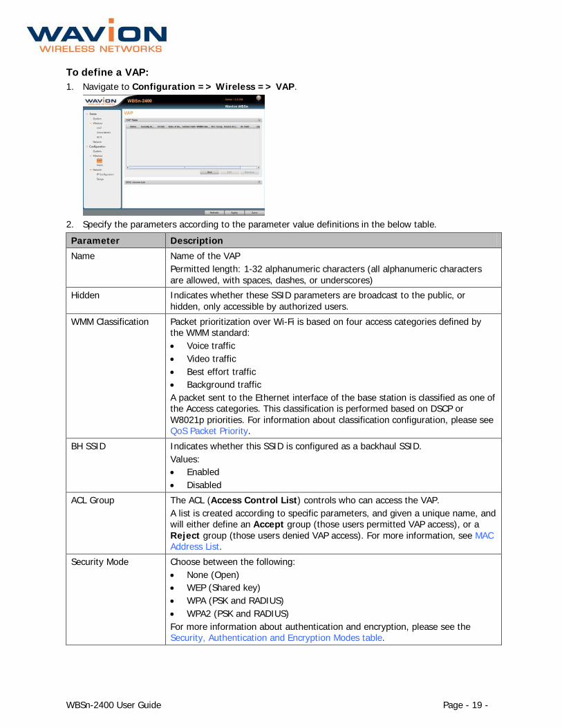
To define a VAP: 1. Navigate to Configuration => Wireless => VAP.
2. Specify the parameters according to the parameter value definitions in the below table.
Parameter Description
Name Name of the VAP Permitted length: 1-32 alphanumeric characters (all alphanumeric characters are allowed, with spaces, dashes, or underscores)
Hidden Indicates whether these SSID parameters are broadcast to the public, or hidden, only accessible by authorized users.
WMM Classification Packet prioritization over Wi-Fi is based on four access categories defined by the WMM standard: • Voice traffic • Video traffic • Best effort traffic • Background traffic A packet sent to the Ethernet interface of the base station is classified as one of the Access categories. This classification is performed based on DSCP or W8021p priorities. For information about classification configuration, please see QoS Packet Priority.
BH SSID Indicates whether this SSID is configured as a backhaul SSID. Values: • Enabled • Disabled
ACL Group The ACL (Access Control List) controls who can access the VAP. A list is created according to specific parameters, and given a unique name, and will either define an Accept group (those users permitted VAP access), or a Reject group (those users denied VAP access). For more information, see MAC Address List.
Security Mode Choose between the following: • None (Open) • WEP (Shared key) • WPA (PSK and RADIUS) • WPA2 (PSK and RADIUS) For more information about authentication and encryption, please see the Security, Authentication and Encryption Modes table.
WBSn-2400 User Guide Page - 20 -
Parameter Description
Limit number of stations
Controls the number of clients associated to the base station. • If Enable Limit is selected, a numerical limit can be specified. • If Enable Limit is not selected, any number of clients can associate to the
base station.
There is no default limitation on the number of associations supported.
WBSn supports up to 256 associated clients per radio, utilizing the Open security mode.
Note: For WBSn-2400 v 1.0, up to 127associated clients per radio are supported.
In other security modes the maximum number of associated clients is different. For more information, please refer to the Security, Authentication and Encryption Modes table.
Security, Authentication, Encryption Modes and Maximum Associations
Security Mode Authentication Mode Encryption Mode Max Associations
None Open system None 256 (127 in v1.0)
WEP (Only available for the first defined VAP)
• Shared key • WEP/40 • WEP/104
• 127 • 127
WPA • PSK (Pre-shared key) • Radius
• TKIP + AES • 110
WPA2 • PSK (Pre-shared key) • Radius
• AES • 110
WPA\2 • PSK • Radius
• AES + TKIP • 110
WBSn supports the capability of limiting the number of maximum associations per VAP. The limit can be set to any value between 0 and 50, regardless of the security of the VAP.
QoS (Quality of Service) Packet Priority Wireless Multimedia Extensions (WME), also known as Wi-Fi MultiMedia (WMM), provide basic QoS features to IEEE 802.11n networks. WMM prioritizes traffic on the wireless interface using four Access Categories (AC): • Voice • Video • Best Effort • Background
Traffic is prioritized by these access categories, and the implementation defined by the WMM standard. Traffic is therefore suitable for applications that require QoS over Wi-Fi, (for example, Voice over IP (VoIP)).

WBSn-2400 User Guide Page - 21 -
Note: In order to allow QoS through the WBSn-2400, both ends of the network (CPE on the wireless side and the switch/router on the Ethernet side) should support the same priority tagging. This permits the marking of a specific packet with a specific priority. WBSn supports DSCP, 802.1p and Auto priority tagging.
When DSCP is selected, WBSn inspects the incoming IP packets and determines the WMM priority according to the DSCP priority bits. When W8021p is selected, WBSn inspects the incoming layer-2 packets and determines the WMM priority according to the VLAN-priority bits. When Auto mode is selected, WBSn checks whether a VLAN tag exists, and if it does, it determines the priority according to the VLAN priority. Otherwise, the priority is determined by the DSCP value.
Downlink (data sent from the network to the user), a packet from the wire-line network is received by the WBSn, and its priority detected. The packet will be prioritized over the air according to WMM AC prioritization. When the packet reaches the CPE, the CPE passes it to its LAN interface according to the packet definition.
Uplink (data sent from the user to the network), the CPE will detect the priority (as defined at the CPE) and will pass the frame with the correct WMM AC characteristics, thus providing the priority classification on the wireless side.
To view the status of a VAP:
To view the status of any or all defined VAPs, navigate to Status => Wireless => VAP.
Authentication Combinations WBSn-2400 allows the following authentication types and combinations.
• The WPA authentication automatically presumes that the basic 802.11 authentication is Open. WPA defines advanced authentications, either PSK (Pre-Shared Key) or RADIUS. The initial keys are determined during the last phase of the WPA authentication.
• [To be supported in future versions.] When RADIUS Authentication is used, the RADIUS server can determine which VLAN belongs to which user. Note: WBSn-2400 supports multiple VLAN per VAP.
• Each VAP can have a different RADIUS server configured. This allows for the transportation of several networks over the same infrastructure of WBSn-2400
Encryption Methods Legacy 802.11 clients can either connect using the Open authentication (see above), or WEP. In WEP, the encryption key can be either 40bit or 104bit. In WPA, WBSn-2400 supports TKIP and AES encryptions.
Wireless Associations The Wireless associations list is a list of clients that are connected to the base station. You can access this list by navigating to Status => Wireless => Associations, where the following list parameters are displayed. Parameter Description
IP Address IP address of the associated station
MAC MAC (Media Access Control) address of the associated station
SSID SSID to which the station is associated
RSSI dBm The RSSI (Received Signal Strength Indicator) power received by the WBSn base station from the associated station.

WBSn-2400 User Guide Page - 22 -
Parameter Description
TX Rate The average PHY Rate (modulation) at which the base station transmits to the associated station
RX Rate The average PHY Rate (modulation) at which the associated station transmits to the base station
State Indicates the status of the station’s connection: • Disconnected • Association_Processing • Associated • Disconnecting
Est. Range Estimated range of client from WBSn
WMM A value of 'yes' in this field indicates that the associated station supports the WMM protocol
Auth. Status Radius authentication state
Radio 2.4 GHz, or 5.0 GHz, or 2.4 GHz + 5.0 GHz
PS Power Save status
11N Indicates whether the associated station supports 802.11n protocol
Restricting access to the wireless network
MAC Access List The MAC access list is a group of client MAC addresses that can be created and either permitted or denied access to the network (reject/accept). A maximum of 1000 entries can be added. These groups can be assigned to VAPs through the VAP configuration window. For more information about VAPs, see here.
To specify MAC access 1. Navigate to Configuration => Wireless => VAP => MAC Access List. The following window is
displayed:
2. Specify the name of the group of MAC addresses, and define whether to reject or accept it.

WBSn-2400 User Guide Page - 23 -
3. Click Add. The following window is displayed:
4. Specify the parameter values according to the following table:
Parameter Description
Type Values: OUI: Identifies the MAC address by the first three bytes, determining the Vendor ID Static: Requires the entire MAC address
Address Prefix Either specify the OUI numbers, or enter the full MAC address
Description The name of device to whom this MAC belongs.
5. Click Apply, and the click Add. The group of MAC addresses is listed in the group table.
Radio Configuration
To Configure Your Radio Settings 1. Navigate to Configuration => Wireless => Radio. 2. Select the required channel bandwidth and specify the parameters, as described in the following
table.
Note: Only 2.4 GHz is available for this WBSn release. 5.0 GHz will be available for future releases.
Field Description
Radio Specify that the radio modules are operational, or turn them off for purposes such as maintenance.
Channel Width 20 MHz or 40 MHz
Channel Specify the channel/frequency (1-11/13 depending on regulation)
TX Power Specify the transmission power between 3-25 dBm (depending on regulation)
ACS (Online, Offline) The Automatic Channel Selection (ACS) utilizes an embedded algorithm to scan for the best channel with which your base station can work, ensuring optimal capacity, minimal interference and maximum performance.
Offline ACS performs a full scan of the available channels while the system is down, determining which channels are the best and most interference-free, and prompting you to choose these channels prior to resuming and reactivating the system.
Online ACS runs in the background while the system is up, checking the available channels, and whether any of those available are better for use than the channels currently being utilized.
Note: The Online ACS will be enabled in a future release

WBSn-2400 User Guide Page - 24 -
To Access Automatic Channel Selection 1. Select Configuration => Wireless => Radio. 2. Expand the required field (Online ACS or Offline ACS) to specify the parameters, described in the
following table.
Parameter Description
Offline ACS
Select Channel button Click to select a specific channel
Scan Click to scan, then define the following parameter values: • Optimization mode:
o Throughput o Range
• Auto Switch • On • Off • Estimate Scan Time (specify)
Stop Scan button Stops scan
Online ACS (To be available in a future release)
Optimization mode Values: • Throughput • Range
Auto. Switch Switches Online ACS on and off automatically
Enable/Disable Select whether or not to run online scanning.
Network/Ethernet Interface – Setting up WLANs A WLAN is the combined entity of VAPs and VLANs. Each VLAN has a unique IP address, which you must configure.
It is possible to create several networks that work in parallel on the same WBSn-2400. This can be done by creating several VAPs mapped to several VLAN. Each VAP will represent a different broadcast domain on the wireless interface, isolated from other VAPs by using different broadcast keys, with the broadcast domains on the Ethernet interface separated by the VLAN.
To Configure the Default IP 1. Navigate to Configuration => Network => IP Configuration to specify the default IP for your
VLAN. 2. Click Add (or to specify an existing IP configuration, click Edit). The following dialog is displayed:

WBSn-2400 User Guide Page - 25 -
3. Complete the fields according to the parameters described in the table below.
Parameter Description
IP Address Specify the IP address
IP Method Values: Manual (statically assign an IP address to the VLAN) DHCP: The DHCP server dynamically assigns an IP address to the VLAN
Mask Specify the default subnet mask
Gateway Specify the system default gateway
MTU Range of size that a packet can be
VLAN configuration WBSn implementation distinguishes between network parameters (VLANs) and wireless parameters, such as VAPs. A maximum of 4096 VLANs can be configured on WBSn.
Once you have configured the VLANs, you will then map them to different wireless parameters, to achieve different capabilities according to your requirements.
You can also configure one VLAN as the Management VLAN in the WBSn-2400 system. The purpose of this is to segment the Management and the Clients data traffic. It also provides an option for customers to keep an Open SSID for public traffic and simultaneously manage the WBSn-2400 traffic over a separate VLAN (that can be linked to a secured SSID). The management VLAN can be selected out of the enabled VLAN list.
To Configure a VLAN 1. To specify a new VLAN, navigate to Configuration => Network => Bridge. 2. Expand the VLANs Configuration window, and click Add (or Edit) to configure the VLAN
Parameters. A pop-up box with the following parameters is displayed.
Parameter Description and values
VLAN ID This ID should be unique and must be supported by the backbone equipment that is connected to the WBSn through the Ethernet port.
VLAN Name Edit the VLAN name as required.
Ethernet Determine whether the VLAN is configured in the Ethernet interface, and define whether it is tagged or untagged.
VAP 1-6 Determine whether the VLAN is configured in any of the VAP interfaces and define whether they are tagged untagged, or none.
3. Scroll back up to the VLANs section, and specify a VAP for the VLAN.
Once you have at least one VLAN defined, you can then specify the Management VLAN.
Tagging VLAN
When configuring more than one VAP per WBSn unit, a VLAN can be created. Each VLAN should be tagged with a different VLAN ID so that networks can be identified at backbone entry.
The default VLAN has a VLAN ID that is equal to 1, and has tagging disabled by default, leaving the data untagged.

WBSn-2400 User Guide Page - 26 -
Bridge Enables you to configure how VLANs are defined and structured in the system, and with which VAP each VLAN is paired. For more information, see Configuring a VLAN.
Mapping VLANs to VAPs
VAPs are configured as Wireless interfaces. The table below shows the mapping of VLANs to VAPs.
Interfaces
Index VLAN ID Ethernet Management VAP1 VAP2 VAP 3 VAP4
1 3599 √ √ √
2 101 √ √
3 73 √ √ √
As displayed in the above table, a single VLAN can be mapped to multiple VAPs (e.g. VLAN 73), and multiple VLANs can be passed to a single VAP (e.g. both VLAN 101 and VLAN 73 are linked to VAP 1). In such a situation, one untagged VLAN can be defined per interface (e.g. Ethernet, VAP).
When a VLAN is configured to be tagged on a VAP, a CPE that supports VLAN tagging on the wireless interface must be used.
WBSn-2400 User Guide Page - 27 -
Administration The Administration section enables you to manage your system, troubleshoot, and specify various administration parameters.
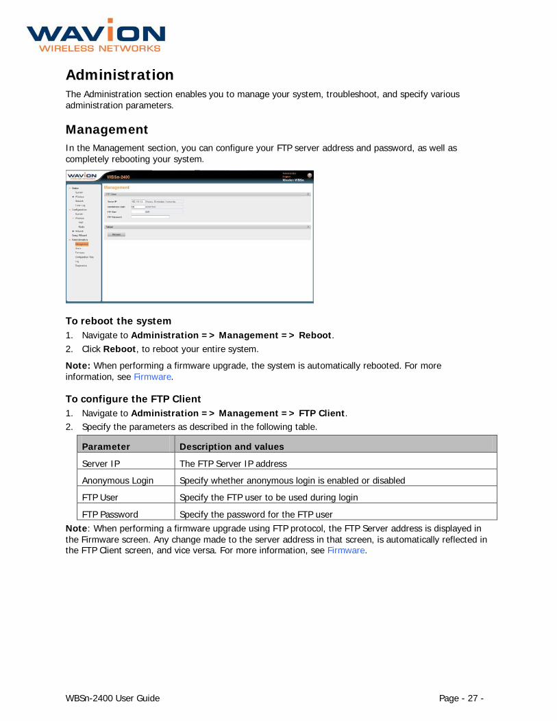
Management In the Management section, you can configure your FTP server address and password, as well as completely rebooting your system.
To reboot the system 1. Navigate to Administration => Management => Reboot. 2. Click Reboot, to reboot your entire system.
Note: When performing a firmware upgrade, the system is automatically rebooted. For more information, see Firmware.
To configure the FTP Client 1. Navigate to Administration => Management => FTP Client. 2. Specify the parameters as described in the following table.
Parameter Description and values
Server IP The FTP Server IP address
Anonymous Login Specify whether anonymous login is enabled or disabled
FTP User Specify the FTP user to be used during login
FTP Password Specify the password for the FTP user Note: When performing a firmware upgrade using FTP protocol, the FTP Server address is displayed in the Firmware screen. Any change made to the server address in that screen, is automatically reflected in the FTP Client screen, and vice versa. For more information, see Firmware.

WBSn-2400 User Guide Page - 28 -
Users In the Users section, you can manage which users are allowed to access the system, and allocate specific permissions per user, according to their definition in the system.
To add a user 1. Navigate to Administration => Users. 2. Click Add. The following dialog is displayed.
3. Specify the parameters, as described in the following table, and click Apply.
Parameter Description and Values Username Name of the user.
Permission Specify the permission assigned to a particular user. Values: • Viewer • Administrator • Technician
Password Specify a password for the user.
Confirm Password Confirmation of the user password.
Note: To edit an already existing user, highlight the user row in the screen, and click Edit.
Firmware The firmware section enables you to upgrade your system firmware, or to rollback to a previously saved version. Upgrading can be performed using either via HTTP or FTP servers, according to your requirements. For information about configuring the FTP server address and password, see Configuring an FTP Client.
Note: It is strongly recommended that upgrades be performed at a time when the system is not fully utilized (e.g. during late-night hours, when traffic is low).

WBSn-2400 User Guide Page - 29 -
To upgrade firmware using FTP 1. Navigate to Administration => Firmware.
2. In the Upgrade Protocol field, select FTP from the drop-down list. The FTP Server IP field is
automatically populated by the information specified in Configuring an FTP Client. 3. In the Upgrade File Path (FTP) field, specify the path to the upgrade file provided to you under
separate cover by Wavion. Note: The Upgrade File (HTTP) field is disabled.
4. Click Upgrade. A notification message is displayed, informing you of the expected time that it will take for the upgrade to be performed.
Proceed directly to Switching to the Upgraded Firmware Version.
To upgrade firmware using HTTP 1. Navigate to Administration => Firmware.
2. In the Upgrade Protocol field, select HTTP from the drop-down list. The FTP Server IP field is
automatically disabled. 3. In the Upgrade File (HTTP) field, click Browse, and navigate to the path where the upgrade file,
provided to you under separate cover by Wavion, was saved. Note: The Upgrade File Path (FTP) field is disabled.
4. Click Upgrade. A notification message is displayed, informing you of the expected time that it will take for the upgrade to be performed.
Proceed directly to Switching to the Upgraded Firmware Version.
WBSn-2400 User Guide Page - 30 -
Switching to the Upgraded Firmware Version Once you have uploaded the upgraded firmware version, you must then officially implement it into your system. The Wavion EMS has two software storage facilities (banks), both displayed in Status => System => Software versions, and described in the below table.
Field Description and Values Main Firmware Indicates the name of the current loaded version of the administration
firmware (i.e. the version currently running)
Shadow Firmware Indicates the name of the new or the previously loaded version of the administration firmware
Note: Until you have performed the above procedure, only the Main Firmware field in Status => System => Software versions is populated.
1. Once the new upgrade version of the administration firmware has been uploaded to the Shadow Firmware bank, click Switch. This enables you to switch over to the newly uploaded version.
2. The system performs a reboot, and when it powers up, does so using the new version of the firmware.
3. If at this stage you wish to revert back to the previous version of the administration software, you can click Switch again. The system will once more perform a reboot, and the system will power up using the previously loaded version of the firmware.
Note: At this stage, it is recommended that verify and check your connectivity with the Base Station. For more information, see Diagnostics.
Using the Rollback Procedure After a firmware upgrade procedure is performed, a new configuration file is included in the upgrade, which will adopt the current configuration settings, once the newly upgraded firmware is run.
This configuration file may contain new features that could modify current configurations; or, even if no new features were included in the upgrade, but new configurations were specified by the user, a newer version of the configuration file is created.
If you wish to revert back to the previous firmware and the previous configuration file, you need to perform a Rollback procedure.
To Rollback the Firmware 1. Navigate to Administration => Firmware. 2. Click Rollback. The following message is displayed:
3. Click yes to reboot your system, and rollback to the previous firmware and configuration file.
WBSn-2400 User Guide Page - 31 -
Diagnostics You can utilize this section to verify IP connectivity to the management IP, and also to create a Wavion Tech Support File.
To Ping the WBSn Unit’s IP Address
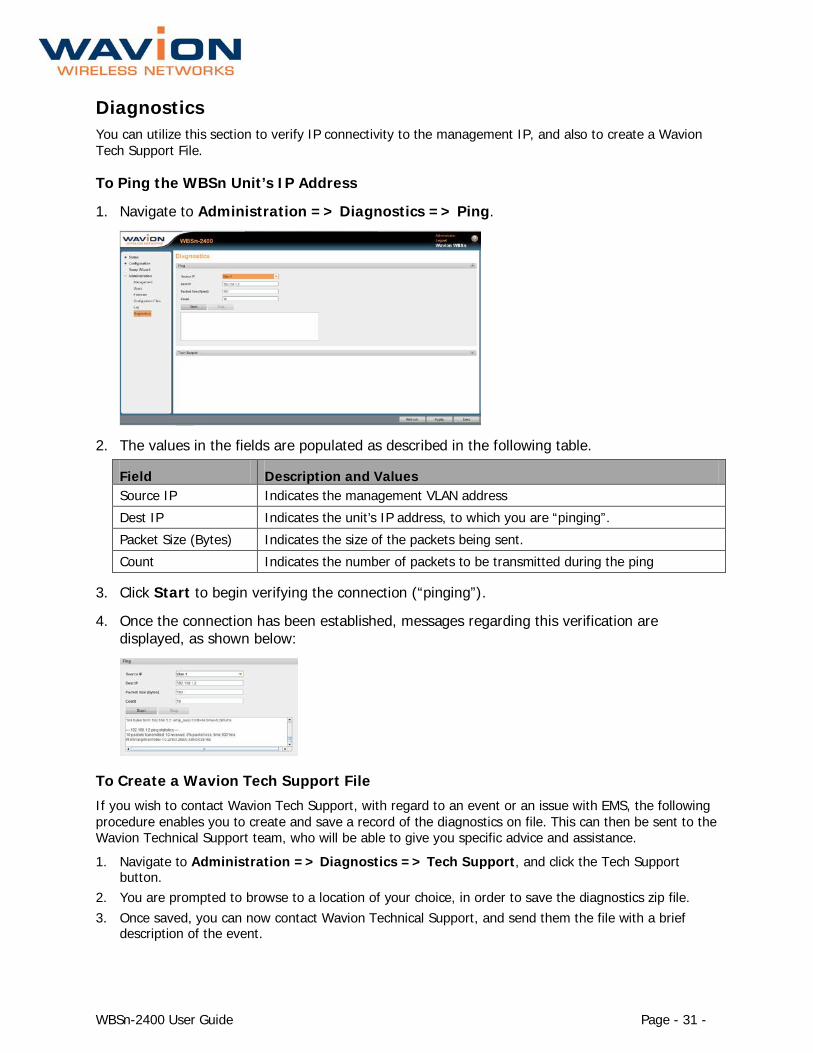
1. Navigate to Administration => Diagnostics => Ping.
2. The values in the fields are populated as described in the following table.
Field Description and Values Source IP Indicates the management VLAN address
Dest IP Indicates the unit’s IP address, to which you are “pinging”.
Packet Size (Bytes) Indicates the size of the packets being sent.
Count Indicates the number of packets to be transmitted during the ping
3. Click Start to begin verifying the connection (“pinging”).
4. Once the connection has been established, messages regarding this verification are displayed, as shown below:
To Create a Wavion Tech Support File
If you wish to contact Wavion Tech Support, with regard to an event or an issue with EMS, the following procedure enables you to create and save a record of the diagnostics on file. This can then be sent to the Wavion Technical Support team, who will be able to give you specific advice and assistance.
1. Navigate to Administration => Diagnostics => Tech Support, and click the Tech Support button.
2. You are prompted to browse to a location of your choice, in order to save the diagnostics zip file. 3. Once saved, you can now contact Wavion Technical Support, and send them the file with a brief
description of the event.

WBSn-2400 User Guide Page - 32 -
Configuration files You can use this section to restore your configuration to the factory default settings.
To restore factory default configuration 1. Navigate to Administration => Configuration Files. 2. Click the Configuration Files button to automatically back up your configuration file, and set the
configuration back to the factory default
Log Navigate to Administration => Log to view and configure logs of system events.
• The syslog is a way to send the events to a syslog server that keeps them • The SNMP traps section displays SNMP protocol configuration and severity, and enables you to set a
specific event to a customer severity, regardless of the configured factory default severity. • The Event log displays the systems most recent events.

WBSn-2400 User Guide Page - 33 -
Appendix A: Troubleshooting We hope your experience with the WBSn-2400 is as smooth as possible. In this section we provide tips to solve some common problems.
Basic Troubleshooting
Problem Solution
Default user and password User: admin Password: admin
Unable to Ping or HTTP the new unit • Check the Power • Is the BST Operational? Check the LED, make sure it shows
green on the status • WBSn-2400 default IP Address is 192.168.1.1 /24 mask
Client unable to acquire an IP Address from DHCP Server
• Is the BST Operational? • Check the DHCP Server. Use Static IP to test the DHCP
configuration • Check for Interference. Noise level should be between -
97dBm to -82dBm
Clients experiencing low throughput • Check the Network Interfaces, 802.11b/g for Wi-Fi activity and try to select a better channel using the Automatic Channel Selection (ACS).
• Check for Interference. Noise level should be around -97dBm to -82dBm
• Check the client’s modulation rate e.g. 54Mbps, 48Mbps, 11Mbps....
LED Descriptions
LED Status Description
LED OFF No power (and very early startup)
Red Booter (U-boot) running:
Orange Rescue Mode running
Green Firmware running
RADIO Radio LED will be off during entire startup and remain active only at runtime (when status LED is steady green):
Steady green All Radios are On.
OFF All Radios are Off
Orange Some of the Radios are Off and some are On
WBSn-2400 User Guide Page - 34 -
Appendix B: Frequently Asked Questions Q: Does the WBSn-2400 base station support standard off-the-shelf 802.11b/g/n NIC cards?
A: Yes, the WBSn-2400 base station supports the 802.11b/g/n standard.
Q: I have WEP configured on my radio but I am unable to connect to the Internet.
A: WBSn base station supports all the security modes defined by 802.11 and Wi-Fi Alliance: Open, WEP, WPA and WPA2. In the case of WEP mode, both 64-bit (also known as 40-bit) and 128-bit WEP (also known as 104-bit) encryptions are supported. In addition, both Open and Shared Key Authentications are supported in WEP mode.
Note: Security WEP can only be configured on VAP-1.
Note: Both ends must have the same configuration for data transfer. The key length and the key itself must match at both ends, as must the Authentication type.
WBSn requires that you enter the WEP key in hexadecimal format. Some devices allow ASCII text or a pass phrase. This value must be converted into hexadecimal format and entered into the WBS.
If the devices have multiple keys, the same key number must be used on both devices. For example; if WEP Key 1 is used on one device, WEP Key 1 must be used on the WBSn.
Q: How do I log in to the WBSn Management page?
A: Access to the WBSn is gained through the following IP address and credentials:
Default IP: http://192.168.1.1/24
Username: admin
Password: admin
To access WBSn, ensure that your computer is set to an IP address similar to 192.168.1.2, with a subnet mask of 255.255.255.0.
Once you have configured your computer, open a web browser and browse to: http://192.168.1.1. The login prompt for the WBSn should now be displayed.
Q: How do you set up an IP address on the WBS?
A: See this section in the User Guide.
Q: How do you extend the coverage of the WBS?
A: There are several ways to extend the WBSn coverage area. These are the most important methods:
1. Increase the transmitter power level parameter of the existing WBSn in order to extend the coverage. 2. Position the WBSn base stations optimally at least 1m away from any metal object. 3. Use a strong transmission client (CPE). 4. Increase the transmission/reception capabilities of the client antenna by using an RF Booster. 5. Run ACS, and try working in a different channel in which there is less interference.
Q: What is the typical range for a WBSn base station?
A: The answer to this question depends on a number of factors including:
• The data rate (bandwidth) that you expect to receive at remote locations • The device (CPE/NIC) that resides at the remote end • The level of interference at the active channel

WBSn-2400 User Guide Page - 35 -
• The terrain of the covered area.
In rural areas where the WBSn base station is installed relatively high (10m above other buildings), and there are no interferences, the range can be up to 20 km.
Q: How can I determine the best channel to work in?
A: Use the ACS feature to search for a clean frequency
Q: Does WBSn base station support roaming?
A: The Wavion Base Station supports the part of 802.11f, which supports handover between access points that reside on the same Layer-2 domain.
The WBSn handover implementation sends a Layer-2 packet with the source address of a newly associated client. This packet is sent as broadcast message allowing all Layer-2 devices in the network to update their MAC address caches.
This solution will work if the backhaul network is configured as a flat Layer-2 network. When the network is composed by multiple IP subnets, another device (e.g. a session controller) should handle roaming across subnets.
Q: Is it possible to co-locate a number of WBSn base stations??
A: Yes, three WBSn units can be co-located. A minimum of 8 meters separation is recommended when all units are on the same RF channel. However, the units will suffer from throughput performance due to mutual interference.
A one-meter separation is possible when units are operating on different RF channels 1,6,11. It is highly recommended to have as much distance as possible between units and to use RF channels 1,6,11 in order to reduce throughput degradation.
We recommend that you avoid installing the units at the same height, by leaving a vertical distance of at least 1 meter between them.
Q: What is the minimum distance required between two WBSn units?
A: Two meters is the minimal recommended separation.
Q: What are the tower installation requirements?
A: WBSn must be installed at least 1 meter away from any adjacent metal object.
Q: What are the pole installation requirements?
A: WBSn must be installed with antenna higher than the end of the pole.
Q: What is the nominal noise level for optimal performance of WBSn?
A: Nominal noise level without interference is -97dBm. Utilize the ACS feature to search for a clean frequency with a noise level between -85dBm to -97dBm. Higher values indicate higher noise levels due to interference.
Q: What is the maximum Ethernet cable length that can be used with a POE?
A: The maximum cable length is 100 meters.
Q: Where is the WBSn reset button?
A: The reset pin hole button is located below the USB port. To reset the system to factory default parameters press the button until the STATUS LED is on steady with a red light.

WBSn-2400 User Guide Page - 36 -
Q: How many clients can associate to WBSn?
A: The WBSn can physically handle up to 250 MAC addresses. However, because Wi-Fi is a shared platform and every Wi-Fi base station acts as a wireless hub, the performance of each user decreases as the number of users increases.
Q: Is it possible to limit the number of associated clients?
A: Yes. The WBSn can support up-to 256 associated clients per radio (supported by v1.1 onwards). The WBSn can limit the number of clients associated to any value between 0 and 50. Client association will be refused after the limit is reached. For more information, see the Security, Authentication and Encryption Modes table.
Q: How to deny association to specific MAC addresses?
A: The list of MAC addresses you wish to block can be uploaded or enter manually. For more information, see MAC Access List.
Q: Does the WBSn support QoS?
A: Yes. The WBSn support QoS while implementing the WMM protocol. For more information, see the Security, Authentication and Encryption Modes table.

WBSn-2400 User Guide Page - 37 -
Appendix C: Hardware Specification
Product Weight (kg) Total (kg) Omni 7
7.8 Arm 0.4 Post clamp (die cast) 0.4 Sector (with die cast mechanism) 2.4 2.8 Post clamp (die cast) 0.4 Omni 3-ant (without antenna) 1.4
2 3-ant (all of them) 0.2 Post clamp (die cast) 0.4

WBSn-2400 User Guide Page - 38 -
Appendix D: Specifications and Patterns The chapter describes antenna specifications and patterns for the antennas supplied with the Wavion WBSn-2400-O.
MT_341017NA_SN_101_EL 2.4 GHz Antenna The following describes the patterns for the antenna:

WBSn-2400 User Guide Page - 39 -

WBSn-2400 User Guide Page - 40 -

WBSn-2400 User Guide Page - 41 -
Glossary
Acronym Description
2P Two-Phase or Split Phase
2W Two-Wire
3W Three-Wire
AC Alternating Current
ANSI American National Standards Institute
AWG American Wire Gauge
C Celsius
CAT Category
CCK Complementary Code Keying
CFR Code of Federal Regulations
CSA Canadian Standard Association
dB Decibels
dBi Decibels Relative to an Isotropic Radiator
DBPSK Differential-Binary Phase-Shift Keying
DC Direct Current
DQPSK Differential-Quadrature Phase-Shift Keying
DSSS Direct-Sequence Spread Spectrum
EMC Electromagnetic Compatibility
EN IEC standard
ESD Electrostatic Discharge
FCC Federal Communications Commission
Hz Hertz
IEEE Institute of Electrical and Electronics Engineers
IP68 Ingress Protection Standard
ISTA International Safe Transit Association
LAN Local Area Network
Mbps Megabits Per Second
MHz Megahertz
MIL-STD Military Standard
N Neutral
NEC National Electrical Codes
NEMA National Electrical Manufacturers Association
OFDM Orthogonal Frequency Division Multiplexing

WBSn-2400 User Guide Page - 42 -
Acronym Description
P Phase
PE Protective Earth
PoE Power over Ethernet
RJ45 Registered Jack 45
RSS Received Signal Strength
Rx Receive
RXD Receive Data
TUV Technical Inspection Association
Tx Transmit
TXD Transmit Data
UL Underwriters Laboratories
VAC Voltage (Alternating Current)
VCCI Voluntary Control Council for Interference
VDC Voltage (Direct Current)
W Watts


