86
Westinghouse Non-Proprietary Class 3 WCAP-15338-A October 2002 A Review of Cracking Associated with Weld Deposited Cladding in Operating PWR Plants

Westinghouse Non-Proprietary Class 3
WCAP-15338-A October 2002
A Review of Cracking Associated with Weld Deposited Cladding in Operating PWR Plants


WESTINGHOUSE NON-PROPRIETARY CLASS 3
Westinghouse Electric Company LLC P.O. Box 355
Pittsburgh, PA 15230-0355
©2002 Westinghouse Electric Company LLC All Rights Reserved
o:\5041-A.doc:1b-090908
WCAP-15338-A
A Review of Cracking Associated with Weld Deposited Cladding in Operating PWR Plants
Warren Bamford R. D. Rishel
October 2002
Reviewer:________________________________ C. E. Meyer, Technical Coordinator WOG License Renewal Programs
Approved:________________________________ S. A. Swamy, Manager Structural Mechanics Technology
Funded by:
Westinghouse Owners Group (WOG) Life Cycle Management/License Renewal (LCM/LR) Program
Prepared by Westinghouse Electric Company for use by members of the Westinghouse Owners Group. Work performed in Shop Order MUHP-6110 under direction of the WOG LCM/LR Program Core Group.


October 2002 o:\5041-A.doc:1b-090908
October 2002 o:\5041-A.doc:1b-090908

October 2002 o:\5041-A.doc:1b-090908
October 2002 o:\5041-A.doc:1b-090908

October 2002 o:\5041-A.doc:1b-090908

October 2002 o:\5041-A.doc:1b-090908

October 2002 o:\5041-A.doc:1b-090908
October 2002 o:\5041-A.doc:1b-090908

October 2002 o:\5041-A.doc:1b-090908


iii
October 2002 o:\5041-A.doc:1b-090908
DISCLAIMER OF RESPONSIBILITY
This report was prepared by Westinghouse as an account of work sponsored by the Westinghouse Owners Group (WOG). Neither the WOG, any member of the WOG, Westinghouse, nor any person acting on behalf of any of them:
(a) Makes any warranty or representation whatsoever, express or implied, (I) with respect to the use of any information, apparatus, method, process, or similar item disclosed in this report, including merchantability and fitness for a particular purpose, (II) that such use does not infringe on or interfere with privately owned rights, including any party’s intellectual property, or (III) that this report is suitable to any particular user’s circumstance; or
(b) Assumes responsibility for any damages or other liability whatsoever (including any consequential damages, even if the WOG or any WOG representative has been advised of the possibility of such damages) resulting from any selection or use of this report or any information apparatus, method, process, or similar item disclosed in this report.
COPYRIGHT NOTICE
This report bears a Westinghouse copyright notice. You as a member of the Westinghouse Owners Group are permitted to make the number of copies of the information contained in this report which are necessary for your internal use in connection with your implementation of the report results for your plant(s) in your normal conduct of business. Should implementation of this report involve a third party, you are permitted to make the number of copies of the information contained in this report which are necessary for the third party's use in supporting your implementation at your plant(s) in your normal conduct of business if you have received the prior, written consent of Westinghouse to transmit this information to a third party (or parties), and the appropriate agreements are in place to protect the proprietary information for the proprietary version of the report. All copies made by you must include the copyright notice in all instances and the proprietary notice if the original was identified as proprietary.


v
October 2002 o:\5041-A.doc:1b-090908
EXECUTIVE SUMMARY
The issue of underclad cracking in reactor vessels has existed since 1970 when it was first discovered at a European vessel fabricator. The cracks are in base metal immediately beneath the clad, and are created as a result of the weld deposited cladding process. Westinghouse completed an evaluation of this issue in 1971, concluding that integrity could be assured for the entire 40 year design life. Westinghouse submitted it to the Atomic Energy Commission (AEC), and the AEC concurred, issuing a letter on September 22, 1972. This type of underclad cracking is commonly referred to as reheat cracking.
In late 1979, underclad cracking in reactor vessels resurfaced in the form of ‘cold cracking’. Supplemental inspections confirmed that such cracking existed in a select group of vessels. Fracture evaluations of the detected flaw indications confirmed their acceptability for a 40 year design life.
Since license extensions are now being sought for 60 years of operation, the underclad cracking issue has again resurfaced, and so this report contains a further assessment of the issue. The mechanisms of cracking are well understood, and the effect of the cladding on the structural integrity of a vessel with underclad cracks has been assessed as very small.
Underclad cracks (reheat and cold cracking) are very shallow, confined in depth to less than approximately 0.295 inch immediately beneath the cladding and have lengths up to 2.0 inches. All indications identified to date have been within the acceptance standards of the ASME Boiler and Pressure Vessel Code, Section XI, Paragraph IWB-3500.
The fatigue crack growth assessment for these small cracks shows very little extension over 60 years, even if they were exposed to the reactor water. Projected crack growth in the inert environment to which they are actually exposed is negligible.
Therefore it may be concluded that underclad cracks are of no concern relative to structural integrity of the reactor vessel for a period of 60 years.
This approved version (WCAP-15338-A) incorporates the revised NRC Final Safety Evaluation, the responses to NRC Requests for Additional Information (RAIs) and the letter providing technical information supporting a requested revision to the original (October 15, 2001) SER.
This version also includes an excerpt from a WOG letter providing the additional information needed to respond to applicant action item (1) in the SER. This information was NOT submitted to the NRC for review and is NOT considered in the conclusions presented in the SER.


vii
October 2002 o:\5041-A.doc:1b-090908
TABLE OF CONTENTS
EXECUTIVE SUMMARY.............................................................................................................v
1 INTRODUCTION ......................................................................................................................1-1
2 MECHANISMS OF CRACKING ASSOCIATED WITH WELD DEPOSITED CLADDING.........................................................................................................2-1
3 PLANT EXPERIENCE WITH DEFECTS IN AND UNDER THE WELD-DEPOSITED CLADDING ................................................................................................................................3-1
4 EFFECTS OF CLADDING ON FRACTURE ANALYSIS .....................................................4-1
5 VESSEL INTEGRITY ASSESSMENT.......................................................................................5-1
6 SUMMARY AND CONCLUSIONS ........................................................................................6-1
7 REFERENCES.............................................................................................................................7-1
8 ATTACHMENT, RAI RESPONSES.........................................................................................8-1
9 ATTACHMENT, WOG LETTERS ...........................................................................................9-1


1-1
Introduction October 2002 o:\5041-A.doc:1b-090908
1 INTRODUCTION
Underclad cracking was initially detected at the Rotterdam Dockyard Manufacturing (RDM) Company during magnetic particle inspections of a reactor vessel in January 1971. These inspections were performed as part of an investigation initiated by RDM as a result of industry observations reported in December 1970. Subsequent evaluations by Westinghouse [1,2,3] concluded that these underclad cracks would not have an impact on the integrity of reactor vessels for a full 40 years of operation. The evaluation was submitted to the Atomic Energy Commission in 1972, and the AEC review concurred [4]. This type of underclad cracking is now commonly referred to as ‘reheat cracking’.
In late 1979, a new form of underclad cracking (‘cold’ cracking) was observed. Westinghouse isolated it to a select group of vessels (only 6 are operating in the U.S.) which were considered suspect. Supplemental inspections of these vessels confirmed the presence of flaw indications indicative of ‘cold’ cracking. Such flaw indications were determined to be acceptable to the standards in the ASME Boiler and Pressure Vessel Code, Section XI, Paragraph IWB-3500. And further, fracture evaluations of the reported flaw indications concluded that there would be no impact on the integrity of the reactor vessels for 40 years of operation.
A number of reactor vessels with confirmed flaw indications indicative of underclad cracks remain in service, and the potential for such cracks cannot be conclusively ruled out in any vessel with weld-deposited cladding. The cracks are in base metal immediately beneath the clad, and are created as a result of the weld deposited cladding process. The purpose of this report is to summarize the present state of knowledge on the issue, and to extend the period of service evaluated to 60 years.


2-1
Mechanisms Of Cracking Associated With Weld Deposited Cladding October 2002 o:\5041-A.doc:1b-090908
2 MECHANISMS OF CRACKING ASSOCIATED WITH WELD DEPOSITED CLADDING
Underclad cracking was initially detected in 1970, and has been extensively investigated by Westinghouse and others over the past 30 years. This cracking has been relatively widespread, having occurred in France and Japan, as well as the USA.
The cracking has occurred in the low alloy steel base metal heat-affected zone (HAZ) beneath the austenitic stainless steel weld overlay that is deposited to protect the ferritic material from corrosion. Two types of underclad cracking have been identified.
Reheat cracking has occurred as a result of postweld heat treatment of single-layer austenitic stainless steel cladding applied using high-heat-input welding processes on ASME SA-508, Class 2 forgings. The high-heat-input welding processes effecting reheat cracking, based upon tests of both laboratory samples and clad nozzle cutouts, include strip clad, six-wire clad and manual inert gas (MIG) cladding processes. Testing also revealed that reheat cracking did not occur with one-wire and two-wire submerged arc cladding processes [1,3]. The cracks are often numerous and are located in the base metal region directly beneath the cladding. They are confined to a region about 0.125 inch deep and about 0.4 inch wide [5].
Cold cracking has occurred in ASME SA-508, Class 3 forgings after deposition of the second and third layers of cladding, where no pre-heating nor post-heating was applied during the cladding procedure. The cold cracking was determined to be attributable to residual stresses near the yield strength in the weld metal/base metal interface after cladding deposition, combined with a crack-sensitive microstructure in the HAZ and high levels of diffusible hydrogen in the austenitic stainless steel or Inconel weld metals. The hydrogen diffused into the HAZ and caused cold (hydrogen-induced) cracking as the HAZ cooled [14]. Destructive analyses have demonstrated that these cracks vary in depth from 0.007 inch to 0.295 inch and in length from 0.078 inch to 2.0 inches. Typical cold crack dimensions were 0.078 inch to 0.157 inch in depth, and 0.196 inch to 0.59 inch in length. As with the reheat cracks, these cracks initiate at or near the clad/base metal fusion line and penetrate into the base metal [15].


3-1
Plant Experience With Defects in Cladding October 2002 o:\5041-A.doc:1b-090908
3 PLANT EXPERIENCE WITH DEFECTS IN AND UNDER THE WELD-DEPOSITED CLADDING
3.1 PWR PLANTS
The U.S. nuclear industry has had many years of service experience with fabrication related defects and/or flaw indications in the cladding, through the cladding into the base metal, and in the base metal just below the cladding. None of these anomalies have caused an integrity problem in over 2000 reactor years of service experience.
3.1.1 Reactor Vessel Experience: Underclad Cracks
An industry task group was established by the Pressure Vessel Research Council as a result of the underclad reheat cracking issue, and this group did a survey of the industry in 1973-74 to identify the number of underclad cracking events which had been observed. A total of 96 survey forms were returned, covering manufactured vessels by 11 different firms on three continents. Of these, five were European, five were American, and one was Japanese.
Of the 96 surveys returned, 26 cases of underclad cracking were reported. The cracking cases were confined to forging materials, SA508 Class 2 (25 cases of 47 surveys) and SA 508 Class 3 (1 of 9 surveys). There were no reported cases in SA 533B, SA 302B, SA 302B nickel modified, or A387D plate materials. The report of the task group [5] contains a statistical study performed to identify the influence of chemistry, tensile strength, and post weld heat treatment on cracking sensitivity. This work was used by the fabricators to refine their process to minimize cracking in the vessels fabricated thereafter.
Westinghouse participated in the PVRC task group, and also performed a large number of preservice inspections of reactor vessels during the 1970s and 1980s to baseline the condition of reactor vessels for future inservice inspections. A number of occurrences of underclad reheat cracking were identified during these examinations. Subsequent inservice inspections of these same vessels with ASME Section XI/Regulatory Guide 1.150 inspection techniques have revealed no measurable growth in these flaw indications.
In late 1979, underclad cold cracking was reported by an European NSSS provider. This type of cracking was observed in SA-508, Class 3 nozzles clad with multiple-layer, strip-electrode, submerged-arc welding processes where preheating and post-heating were applied to the first layer but not to subsequent layers [14]. A review of cladding practices used on vessel nozzle bores in Westinghouse domestic and Japanese plants indicated that a number of vessels were considered suspect in terms of underclad ‘cold’ cracking [16].
The nozzle bores in all six of the domestic plants considered suspect were examined ultrasonically in 1980 and 1981 using a special underclad cracking technique to determine the extent of the underclad ‘cold’ cracking issue [17 - 21]. This ultrasonic technique was demonstrated to be 5 times more sensitive than the ASME Section XI mandated sensitivities [15]. Five of the six vessels contained flaw indications indicative of underclad ‘cold’

3-2
Plant Experience With Defects in Cladding October 2002 o:\5041-A.doc:1b-090908
cracking; all the reported flaw indications met the acceptance standards of the ASME Code Section XI [17 - 21]. Four of the reported flaw indications were destructively analyzed and found to be within the depth/length bounds of 0.295 inch in depth and 2 inches in length for underclad cold cracking [22].
Subsequently these vessels have since undergone inservice inspections (40-month and/or 10-year) in accordance with the ASME Code Section XI with no reported problems. These follow-up examinations make comparisons difficult because of the changing ISI methods through time as well as the different sensitivities applied. One detailed comparison by Rishel and Bamford [6] was reported for inspections of the Sequoyah Unit 1 reactor vessel nozzle bores, in 1993. A special preservice examination of the Sequoyah Unit 1 reactor vessel nozzle bores was done in 1980, by Westinghouse which revealed the extent of any potential underclad cold cracks, including their location and lengths [20]. During the first 10-year inservice inspection for the Sequoyah Unit 1 reactor vessel, performed by Southwest Research (SwRI), flaw indications indicative of underclad cold cracks were detected again using ASME Section XI/USNRC Regulatory Guide 1.150 inspection procedures. It is noted that a specific goal of this inservice inspection was to determine if any of the previously recorded flaw indications had grown during service. The comparison report concluded that there was no observable increase in the size of the assumed underclad cold cracks during the 13 year duration (including at least 10 years of service), but the conclusion was somewhat uncertain because of the different inspection methods employed for the two examinations. A fatigue crack growth analysis showed that little or no growth would be expected, and all the flaws were acceptable to the standards of the ASME Code Section XI, so no further evaluation was required [6].
In the 1983 10-Year Inservice Inspection of the Palisades reactor vessel welds, two small clusters of reheat cracks situated on either side of an intermediate shell longitudinal seam were detected using 60-degree longitudinal wave UT techniques. These indications were individually assigned a conservative flaw size and were determined to be within the allowable limits of Section XI, IWB-3500.
In the 1995 10-Year Inservice Inspection, similar clusters were detected in the same area using 70-degree longitudinal wave UT techniques. The indication depths (0.3 inch), the echodynamic signature of the indication responses, and the rate of occurrence were consistent with the previous interpretation of reheat cracking. There was no evidence that these bands of indications had expanded in number or size.
Additionally, underclad cracks are being monitored in various French plants every 10 years to determine whether there is any measurable growth. No problems have been reported to date.

3-3
Plant Experience With Defects in Cladding October 2002 o:\5041-A.doc:1b-090908
3.1.2 Reactor Vessel Experience: Exposed Base Metal
Various reactor vessels have been operating with exposed base metal surfaces as a result of the removal of the cladding. Some of these reactor vessels are listed below:
A. Yankee Rowe Reactor Vessel
Two clad areas (approximately 1" x 1" and 2" x 4") in the Yankee Rowe reactor vessel were removed due to wear caused by a loose surveillance capsule. These areas had been observed during shutdown. Subsequent measurements of these areas using underwater replication techniques and after approximately 16 years of service has revealed no measurable penetration into the base metal. This result is consistent with the analyses performed for acceptance of these areas [23].
The stainless steel cladding was stitch clad (resistance welded) using 4 ft. x 8 ft. plates. An analysis considering corrosion of these 4 ft. by 8 ft. areas of the bare base metal was performed. It was assumed that with the worn clad areas and cracking in the cladding, the complete cladding/base metal interface would be exposed to the reactor water environment. This analysis showed that this condition was acceptable.
B. Connecticut Yankee Reactor Vessel
The Connecticut Yankee reactor vessel also had the weld-deposited stainless cladding on the reactor vessel worn through because of a surveillance capsule which had come loose. No detrimental effects were observed in over 25 years of service, although the plant is now closed, for other reasons. The reason for this excellent performance has been the primary system chemistry controls.
C. Watts Bar Unit 1 Reactor Vessel Inlet Nozzles
As a result of ultrasonic examination of the Watts Bar Unit 1 nozzles for the assessment of underclad cold cracks, three areas in two inlet nozzles were destructively examined by grinding to determine the depth of four indications [22]. The three clad-removed areas remain in the nozzle. The total size of the three areas is approximately 3 square inches. The plant has operated for at least 7 years with no problems, again because of the tight primary system chemistry control.
D. McGuire Unit 2 Bottom Head Dutchman
The McGuire Unit 2 reactor vessel has an area in the bottom head transition piece between the lower head and vessel shell where stainless steel cladding has been removed. The low alloy steel base metal is exposed to reactor water. The area is 4 to 5 inches long circumferentially, ½ to 1 inches wide vertically and 0.25 inch deep. It is located in the lower head transition cone at 270° approximately 1 ½ inch above the bottom head to transition cone weld. The plant has continued operation with no repair of the exposed area for over ten years with no reported problems.

3-4
Plant Experience With Defects in Cladding October 2002 o:\5041-A.doc:1b-090908
3.1.3 Other Primary System Components Experience
Cracks in the cladding and exposed carbon steel base metal due to cladding removal has also been present in operating steam generators and pressurizers.
Crack-like indications have been found in the cladding of a number of pressurizers and steam generators. Most of these indications have been found in the narrow zone between adjacent strips of cladding. In a number of cases Westinghouse has been involved in the inspection and disposition of these indications and in every case the U.S. NRC has not required a weld repair.
There are at least seven plants where these indications have been found in the steam generator channel head region including:
• Indian Point 3 (replaced in 1989) • Salem 1 and 2 • Turkey Point 3 and 4 • Beznau 1 and 2 (Switzerland) [replaced in 1996]
In each of these plants a surveillance program was established to monitor the growth of these indications. Two follow-up inspections were conducted after the initial findings. In most cases, the monitoring inspections were conducted every 40 months, in conjunction with regular inservice inspections. In the five U.S. plants above, these surveillances detected no significant changes in the indications. This lead the NRC to allow for the programs to be terminated. For the Beznau plants, the surveillances continued until the steam generators were replaced in the early 1990s, with no problems.
In 1990, a number of indications were discovered in the pressurizer cladding at the Connecticut Yankee Plant, as a result of a camera inspection of the bottom head and surge nozzle region. Ultrasonic inspection confirmed that the indications did not penetrate into the ferritic base metal, and so they were acceptable without repair, according to the rules of the ASME Code Section XI. As before, a surveillance program was begun, and after two follow-up inspections were completed showing no change, the NRC allowed the surveillance program to stop [24].
While these results are reassuring, it should be pointed out that in several of the cases cited above the regulators required fracture mechanics analyses to be completed to identify how big a flaw would be acceptable in the region where the indications were found. These analyses have demonstrated that the cladding indications which have been identified will not compromise the integrity of the pressurizers or steam generators.
The Connecticut Yankee pressurizer also contains some small areas of the base metal exposed as a result of grinding. This repair was performed in 1965 and was intended to remove underclad cracks. This pressurizer has been operated for over 30 years with no detrimental effects. Westinghouse performed an engineering evaluation of this condition, considering the effects of both operating and shutdown plant environments, the effect of flow rates, and the effects of galvanic corrosion. The results showed the predicted maximum corrosion penetration for the remaining life of the plant would be 0.173 inch [24]. The actual wall loss was not measured.

3-5
Plant Experience With Defects in Cladding October 2002 o:\5041-A.doc:1b-090908
3.2 BWR PLANTS
Further evidence of acceptable plant operation with cladding removed and base metal exposed can be found in BWR plants.
A decision was made in 1980 to grind off the weld-deposited cladding around the entire circumference of the feedwater nozzles in most U.S. BWR plants. Since that time, both surface and ultrasonic examinations have been required each fuel cycle, and no cracking or corrosion effects have been observed.


4-1
Effects of Cladding on Fracture Analysis October 2002 o:\5041-A.doc:1b-090908
4 EFFECTS OF CLADDING ON FRACTURE ANALYSIS
4.1 INTRODUCTION
Fracture analyses of reactor pressure vessels subjected to thermal shock have employed various assumptions regarding the behavior of the cladding and its influence on the fracture resistance of the vessel. The effect of cladding is also important because of its relevance to underclad cracks. For the most part, it was assumed that the welded clad layer, being lower in strength and higher in ductility than the low alloy pressure vessel steel, would produce no observable effect on the strength or apparent fracture toughness of the pressure vessel. In a positive sense, the clad layer was presumed to have sufficient strength to reduce the stress intensity factor, or crack driving force.
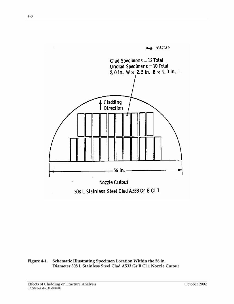
To gain a better understanding of the effect of cladding on the structural behavior in operating reactor vessels, an investigation was conducted using bend bar specimens that were machined from a 308 L stainless steel clad A533 Grade B, Class 1 nozzle cutout free from underclad cracks. The specimens were removed from the nozzle drop-out as shown in Figure 4-1. Three point bending tests were performed over the temperature range -30 to 200°F to evaluate the effect of cladding at both transition range and upper shelf operating temperatures.
To aid in the fracture analysis of stainless steel clad pressure vessel steel, and to help in the interpretation of the bend bar tests, residual stress measurements were made to measure the residual stress profile in and near the fusion zone of stainless steel clad pressure vessel steel. As part of this program, the change in the residual stress profile with temperature in and near the fusion zone was desired. For these measurements a 6.0 in. x 6.0 in. x 11.0 in. (15.2 x 15.2 x 28 cm) (full thickness) test piece machined from a nozzle cutout was used. The nozzle cutout had been subjected to the conventional thermal anneal or post-weld heat treatment given to pressure vessels.
Measurements were made at temperatures of 70, 200 and 400°F. Even though measurements were previously made at 70°F on another heat they were made again in this study because the stress profile could easily be different for the new test piece. The measurements at 70°F were made using the same parting-out and layer-removal procedures as in the previous work. However, because no literature could be found describing techniques for making measurements above room temperature, modifications to the room temperature procedures had to be devised.
This section describes both the fracture tests and the residual stress measurements that were conducted.
4.2 CLADDING EFFECTS ON FRACTURE BEHAVIOR
There has long been a controversy about the effects of weld deposited cladding on the fracture behavior of reactor pressure vessels. To quantify these effects, a series of bend bar fracture tests was carried out on specimens removed from a commercially clad reactor vessel nozzle drop out. This is a cutout from the reactor vessel shell where the nozzle forging is welded in. The
4-2
Effects of Cladding on Fracture Analysis October 2002 o:\5041-A.doc:1b-090908
cladding was Type 308L stainless steel and the reactor vessel steel was A533B Grade B Class 1. The specimen orientations are shown schematically in Figure 4-1.
The bend specimens were 2 inches (5.08 cm) wide, 2.5 inches (6.35 cm) thick, and 9.0 inches (22.9 cm) long. The specimen size was rather large, because this would enable a realistic effect of the cladding (and clad residual stresses) to be seen. The specimens were loaded in three point bending, and each specimen had a penny-shaped crack 0.8 inch (2 cm) long by 0.4 inch (1 cm) deep, as shown in Figure 4-2. With this type of flaw, the residual stresses in the region of the flaw were maintained, so their effect could be measured.
The non-uniformity in cross section along the bend bar length prevented a rigorous fracture mechanics analysis, but the specimens were all geometrically identical. This allowed comparisons to be made based on the final mouth opening displacement of each specimen, which is proportional to the crack driving force, the critical value of which is the fracture toughness. The effect of the cladding on fracture behavior was determined by testing two sets of specimens, one with the crack through the cladding as shown in Figure 4-2, and a second set with the same cross section and same flaw dimensions, but with the cladding removed by machining. The tests were conducted over the temperature range of -30 to 200 °F.
Load-deflection records for both the unclad and clad bend bar specimens were smooth up to the point of unstable fracture, regardless of temperature. The final mouth opening can be viewed as a measure of the fracture resistance of each specimen, and these results are presented in Figure 4-3 as a function of test temperature for both the clad and unclad (base metal) specimens.
The effect of the cladding is seen here as a small but distinct shift in the apparent fracture resistance in the lower range of temperatures. In the temperature range of -30 to 75°F (-34 to 24°C) the apparent shift is approximately 20°F (11°C), but at higher temperatures this effect completely vanishes.
This means that the effect of the cladding on fracture behavior vanishes at temperatures above the transition temperature of the base metal. This conclusion is further proven by the two bend bar results at 200°F (93°C), where the clad specimen failed to experience unstable fracture at a mouth displacement greater than that sustained by a failed unclad specimen (Figure 4-3).
These effects were also seen in a similar series of tests completed by McCabe [7]. He also observed that the clad had no impact on fracture except in the lower portion of the transition region, which for his material was between -58 and -148°F (-50 and -100°C). McCabe concluded that the fracture behavior of the specimens in the transition region was well-predicted by the toughness behavior of the heat-affected zone of the base metal.
McCabe repeated his tests on irradiated bend bar specimens with similar flaws which penetrated the cladding into the base metal for a total depth of 0.4 inches (1.0 cm) [8]. Again the fracture behavior in the transition region was dominated by the heat affected zone behavior, and the effect of the cladding was seen only in the transition temperature range.

4-3
Effects of Cladding on Fracture Analysis October 2002 o:\5041-A.doc:1b-090908
The effect of temperature on the fracture behavior of clad specimens, and clad components can be further understood by studying cladding residual stresses.
4.3 EXPERIMENTAL MEASUREMENTS OF RESIDUAL STRESSES
4.3.1 Introduction to Hole Drilling Stress Measurement
Hole-drilling residual stress measurements at room temperature are made by drilling a small hole in the surface of the test piece and measuring the relieved strains immediately adjacent to the hole [9, 10, 11]. For the present tests, strain measurements were made using rosettes consisting of three 0.062 inch gage length strain gages arranged as shown in Figure 4-4. The hole was drilled at the intersection of the centerlines of the three gages making up the rosette. To make a stress-free machined hole, abrasive jet machining was used [9]. The nominal hole diameter used was 0.080 inch and the nominal depth was one hole diameter. The residual stress measured is a function of the integrated average of the strains relieved over the depth equal to one hole diameter.
Since no technique is described in the literature for hole-drilling residual stress measurements at elevated temperatures, a technique was developed similar to the one used to obtain calibration constants for the hole-drilling method at room temperature [11]. This technique was chosen as it does not require making holes at elevated temperatures. First, to aid in understanding the technique, a description of the room temperature technique will be given as it applies to obtaining calibration constants.
After installing the hole-drilling rosette on a calibration beam, the strain indicator is adjusted to show zero strain. The beam is then incrementally loaded to some predetermined load and then unloaded. Strain measurements are made at each load increment. After unloading the bar the hole is made, and the strain indicator is again rezeroed. The bar is then reloaded incrementally and unloaded with strain measurements made at each load increment. Because the strain gages were zeroed before and after making the holes, the difference in the strain before and after making the hole at any increment represents the relieved strain, from which the stress due to loading can be calculated.
For the elevated temperature tests the same procedure was used except strain changes were obtained when the specimen was heated rather than loaded. The actual procedure involves (a) taking strain readings at test temperatures before making the hole, (b) making the hole, (c) rezeroing the strain indicator and (d) then again taking readings at test temperatures. The stress obtained due to heating can then be calculated from the strain differences.
First, to obtain comparison residual stress measurements in the base metal material, hole-drilling residual stress measurements were made on the cross section of the supplied piece, nominally 0.4 and 1.2 in. beneath the cladding surface. The 0.4 inch (1 cm) depth was chosen to match the depth of the surface flaws in the bend specimens. The measurements in the base metal at 0.4 in. were also used as the base line for the parting-out and layer-removal measurements as will be explained next.

4-4
Effects of Cladding on Fracture Analysis October 2002 o:\5041-A.doc:1b-090908
4.3.2 Parting-Out and Layer-Removal Measurements at 70°F
Parting-out∗ residual stress measurements are made by isolating a section or coupon, as shown in Figure 4-5, from the main body of the component being tested, and measuring the strains relieved in the parted-out piece as a result of this operation. To measure the strains relieved, a two or three-gage rosette is bonded to the piece to be parted-out prior to isolation. If the directions of the principal stresses are known, a two gage rosette can be used to determine the parting-out stresses. In these tests, the direction of the principal stresses are in the directions of gages 1 and 3, as shown in Figure 4-6. For example, in one direction, we have:
)(E 31po με+ε−=σ
where E = Youngs modulus
ε1, ε3 = the measured strains at gauge locations 1 and 3
µ = Poissons ratio (used 0.25, 0.26, and 0.27 for temperatures of 70, 200 and 400°F, respectively)
If the residual stresses in the parted-out piece are completely relieved, or if only bulk stress measurements are desired, this method is complete in itself. However, if residual stresses are still thought to be present in the parted-out piece, as in the present tests, then further measurements using the layer-removal method must be made on the piece. The stresses from both methods must then be combined to get the total stress in the component.
For the parting-out and layer-removal measurements, biaxial strain gages, having a 0.125 inch (0.32 cm) gage length, were mounted at nine locations on the clad surface. The biaxial gage elements were oriented in the directions parallel and transverse to the clad welding direction, because in previous stress measurements on annealed clad steel blocks the principal stresses had been found to be in these directions. However, as the clad surface was curved and too rough for mounting the gages, this surface was ground flat. Because of the grinding, an estimated 0.05 to 0.08 inch (0.127 to 0.203 cm) of material was removed from the clad surface of the specimen. The gages were mounted at the nine locations on 1.30 inches (3.3 cm) centerlines. Six pieces, 1.05 x 1.05 x 0.45 inches (2.67 x 2.67 x 1.14 cm) thick, containing the biaxial gage were then parted-out by careful sawing so as to minimize machining stresses. The sawed surfaces were ground to obtain finished specimens 1.00 x 1.00 x 0.40 inches (2.54 x 2.54 x 1.02 cm) thick.
The residual stresses are determined using the layer-removal method by measuring deformational changes in a specimen as a result of removing stressed material. Usually the method is applied to a plate or beam specimen parted out from a structure, as shown in Figure 4-6. A strain gage is installed on the surface opposite the one of interest. Layers of
*Parting-out is the terminology used for this method in a monograph on residual stress measurements by SAE, and will be used in this report.

4-5
Effects of Cladding on Fracture Analysis October 2002 o:\5041-A.doc:1b-090908
material are then removed from the surface of interest, and the resulting deformational strain changes measured with the strain gage.
In using this method, the assumption is made that the stress is uniform over the entire plane of the specimen parallel to the surface, and varies linearly through the layer removed. Therefore, for accuracy, whenever a high stress gradient is present in the thickness, or z direction, thin layers of material should be removed for each set of strain measurement. For the present tests, layers as thin as 0.010 inch were removed.
If the parting-out method was used to obtain the specimen used for the layer-removal measurements, then, as mentioned, the stresses from both operations must be combined to get the residual stresses that originally existed in the component. These stresses will be called actual residual stresses.
After making the necessary parting-out strain measurements, the pieces were prepared for the layer-removal measurements. Because of the large amount of material to be removed, 0.32 inch, “low stress” grinding was used. Low stress grinding procedures employ a soft wheel and a coolant. The wheel speeds were approximately 2000 ft./min. with small downfeeds having final passes of 0.0002 in./pass. In previous work comparable results were obtained using chemical polishing or low stress grinding. In the area of interest at and near the fusion line, strain measurements were made as mentioned every 0.010 inch; otherwise measurements were made every 0.020 inch.
4.3.3 Parting-Out And Layer-Removal at 200 and 400°F
To obtain the change in surface residual stress due to heating, the specimen and/or structure (Δσt) strains are measured at the desired test temperature before the parting-out operation. The parting-out residual stress at an elevated temperature in a given direction is then related to the change in surface residual stress by:
APPtPo σ−σΔ+σ=σ
The change in stress Δσt does not include stress changes resulting from apparent strain. The effect of temperature on the gages themselves is called apparent strain, and the stresses calculated from these strains will be called apparent stress. Apparent strain is measured strain output as a result of temperature effects on a strain gage when the gage is mounted on a stress-free specimen of the same material as the test piece. The apparent stress (σAPP) is subtracted from Δσt to obtain the actual residual stress change in the specimen surface due to heating.
To obtain the parting-out stress change (Δσt) with temperature for the elevated temperature tests, the three gages on the test block were heated to 200 and 400°F at which time strain measurements were made. From these measurements Δσt was calculated. Apparent stress determinations were made from measurements on specimens after completion of the layer-removal tests, at which time only the clad material remained. Specimens were heated to 200 and 400°F and the apparent strain at these temperatures measured.

4-6
Effects of Cladding on Fracture Analysis October 2002 o:\5041-A.doc:1b-090908
Layer-removal residual stresses at elevated temperatures were measured by making strain readings at the desired elevated test temperature. The test procedure consisted of (1) heating the specimen to the desired test temperature and making strain readings, (2) cooling the specimen to approximately room temperature, and removing incremental layers of material, and (3) heating specimen back to the test temperature and making strain readings. The strain measurements were then used to obtain the layer-removal stresses at temperature. Before starting the layer-removal work, the gaged specimens were heat cycled several times to at least the maximum test temperature and strain measurements made to determine (1) reproducibility of the strain data and (2) whether or not plastic deformation occurred in the specimen.
The layer-removal elevated temperature measurements were made in the same manner as were the room temperature ones except that the specimens were heated to their respective test temperature, 200 or 400 ± 1°F. The specimens were heated in an oil bath to the proper temperature and held at temperature until thermal equilibrium was reached, and then strain measurements made. The low stress grinding was done after the specimens cooled to handling temperature. Before elevated temperature layer-removal testing was started, a parted-out 1.0 x 1.0 x 0.40 inch specimen was directly immersed in 400°F oil and strain measurements made to determine what, if any, effect the thermal shock might have on the specimen. The effect was found to be negligible. For three thermal cycles the overall strain changes were 16 με for gage 1 and 8 με for gage 2.
4.4 CLAD RESIDUAL STRESS RESULTS AND DISCUSSION
The total residual stress (the actual stress in the original clad block before any testing) is the combined results of the layer-removal and parting-out stresses. The layer-removal stresses were found using the strain measurements at the various temperatures.
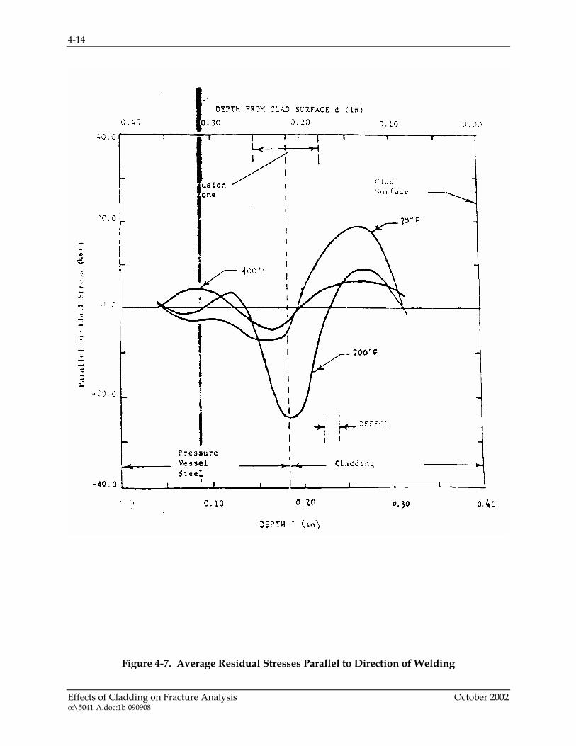
Individual plots of the residual stresses (actual stress) versus depth z through the base metal and cladding at 70, 200 and 400°F (21, 93 and 204°C) are not shown. Instead, average curves of the residual stress parallel to the weld and transverse to the weld at each temperature are given in Figures 4-7 and 4-8, respectively. The average curve is the average of the curves obtained for the two specimens tested at each temperature. The differences are small.
The curves of the residual stresses at 70°F (24°C) shown in Figures 4-7 and 4-8 are similar in shape to that obtained previously at 70°F (24°C) for another nozzle drop-out except that the peak compressive and tensile residual stresses are 15.0 ksi, compared to 20 ksi as shown in the figures. These lower stresses may have been caused by the use of different welding procedures. Underclad defects were noted in the cladding characterized in the earlier test series during layer-removal at the depth shown in Figures 4-7 and 4-8. These defects, which covered as much as 5% of the 1.00 x 1.00 inch cross section of some specimens, may have reduced the stresses measured during the layer-removal phase of the testing. The parting-out stress for all specimens averaged 12.7 ksi higher for the present tests than the previous ones, also indicating a difference in welding procedures.

4-7
Effects of Cladding on Fracture Analysis October 2002 o:\5041-A.doc:1b-090908
The clad residual stress measurements provide an explanation for the fracture behavior observed in the bend bar tests. There is a clearly observable effect of the cladding in the transition region of fracture behavior as shown in Figure 4-3. In this region, the cladding residual stresses have a small but measurable impact on the critical crack mouth opening values, which are a measure of the fracture resistance of the component.
The clad residual stresses result from the difference in thermal expansion coefficient between the stainless steel cladding and the low alloy steel. When the cladding was originally applied, the condition was stress-free. As the weld cooled, the residual stresses developed. The lower the temperature, the higher the clad residual stresses, and in the lower transition region of toughness, these residual stresses can effect failure.
Conversely, as the temperature is raised, two effects occur. The first is that residual stresses decrease, and the second is that the failure mode for the low alloy steel transitions from brittle fracture to ductile fracture. The first effect lowers the stresses, and the second effect decreases and eventually eliminates the effects of residual stresses on the failure.
The clad residual stress measurements show that the stress-free temperature for the cladding is slightly above 400°F (204°C), and this finding is consistent with the results of Ganta et al [12], who calculated the stress free temperature analytically.
The key question which emerges is the effect of the cladding on structural integrity of operating components. It is clear from the tests discussed here that the effects of cladding will be more important at lower temperatures, where the stresses are higher. At temperatures over 180 °F (82 °C) the cladding has virtually no impact on fracture behavior, and this is the very lower end of the temperature range of plant operation. The effects of the cladding must be considered in any structural integrity evaluation, especially for flaws which penetrate the cladding into the base metal, and this requirement exists in the flaw evaluation rules of the ASME Code, Section XI. The actual impact of the cladding on such evaluations is negligible, even for irradiated materials, as also concluded by McCabe [13].
4-8
Effects of Cladding on Fracture Analysis October 2002 o:\5041-A.doc:1b-090908
Figure 4-1. Schematic Illustrating Specimen Location Within the 56 in. Diameter 308 L Stainless Steel Clad A533 Gr B Cl 1 Nozzle Cutout

4-9
Effects of Cladding on Fracture Analysis October 2002 o:\5041-A.doc:1b-090908
Figure 4-2. Clad Bend Bar Specimen Containing a Penny Shaped Surface Flaw

4-10
Effects of Cladding on Fracture Analysis October 2002 o:\5041-A.doc:1b-090908
Figure 4-3. Final Mouth Displacement Versus Temperature for A533 Gr B Cl 1 and 308 L Clad Bend Bar Specimens

4-11
Effects of Cladding on Fracture Analysis October 2002 o:\5041-A.doc:1b-090908
Figure 4-4. Schematic of Hole-Drilling Rosette Showing Strain-Gage Rosette Configuration, Hole Geometry, and Stress Components

4-12
Effects of Cladding on Fracture Analysis October 2002 o:\5041-A.doc:1b-090908
Figure 4-5. Parting-Out Specimen With Three-Gage Rosette Mounted on Surface

4-13
Effects of Cladding on Fracture Analysis October 2002 o:\5041-A.doc:1b-090908
Figure 4-6. Layer-Removal Method Applied to Parted-Out Specimen
4-14
Effects of Cladding on Fracture Analysis October 2002 o:\5041-A.doc:1b-090908
Figure 4-7. Average Residual Stresses Parallel to Direction of Welding

4-15
Effects of Cladding on Fracture Analysis October 2002 o:\5041-A.doc:1b-090908
Figure 4-8. Average Residual Stresses Transverse to Direction of Welding


5-1
Vessel Integrity Assessment October 2002 o:\5041-A.doc:1b-090908
5 VESSEL INTEGRITY ASSESSMENT
5.1 POTENTIAL FOR INSERVICE EXPOSURE OF THE VESSEL BASE METAL TO REACTOR COOLANT WATER
The occurrence of wastage or wall thinning of the carbon steel vessel base metal requires the breaching of the complete thickness of the cladding so that the base metal is exposed to the reactor coolant system (RCS) environment. Thus the total process consists of two sequential steps:
1. Cracking and separation of a portion of the clad weld metal resulting in the exposure of the base metal to the primary water, and
2. Corrosive attack and wastage of the carbon steel base metal due to its exposure to the primary water.
Delamination and separation of the complete clad thickness can occur either by mechanical distress or by micro-cracking induced by metallurgical degradation mechanisms. Examples of mechanical distress are denting and overload (overloads can result in metal plasticity and cracking) cracking caused by mechanical impact loads such as those due to a loose part. Metallurgical mechanisms include intergranular stress corrosion cracking(IGSCC) and transgranular stress corrosion cracking (TGSCC) mechanisms.
IGSCC of the clad metal can occur if the weld is sensitized (chromium depleted grain boundaries) and is exposed to oxygenated water. TGSCC can occur in the cladding only in the presence of a chloride environment. The typical PWR service and shut down RCS chemistry contains oxygen and chloride levels that are significantly below the threshold levels required to initiate either IGSCC or TGSCC.
Thus there is no operative mechanism that can contribute to additional breaching of the clad thickness and result in any exposure of the vessel base metal. Even if the base metal were exposed, the degree of corrosive attack and wastage due to operation is insignificant as evidenced by operational histories and analyses based on corrosion tests.
5.2 FATIGUE USAGE
Review of the reactor vessel shell fatigue analysis in representative Westinghouse reactor vessels reveals that the maximum cumulative fatigue usage factor is 0.04 or less. This shows that the likelihood of fatigue cracks initiating during service is very low.
5.3 ASME SECTION XI – IWB 3500
The underclad cracks which have been identified over the years are very shallow, with a maximum depth of 0.295 inch (7.5 mm). The flaw indications indicative of underclad cracks that have been found during pre-service and inservice inspections are all within the flaw
5-2
Vessel Integrity Assessment October 2002 o:\5041-A.doc:1b-090908
acceptance standards of the ASME Code Section XI, Paragraph IWB 3500. Therefore they are all acceptable without the need for fracture mechanics evaluation.
5.4 FATIGUE CRACK GROWTH
A series of fatigue crack growth calculations were carried out to provide a prediction of future growth of underclad cracks for service periods up through 60 years.
To complete the fatigue crack growth analysis, the methodology of Section XI of the ASME Code was used, with the entire set of design transients applied over a 40 year period. The analysis assumes a flaw of a specified size and shape, and considers each design transient in turn, calculating the crack growth, adding the crack growth increment to the original flaw size, and then repeating the process until all transient cycles have been accounted for.
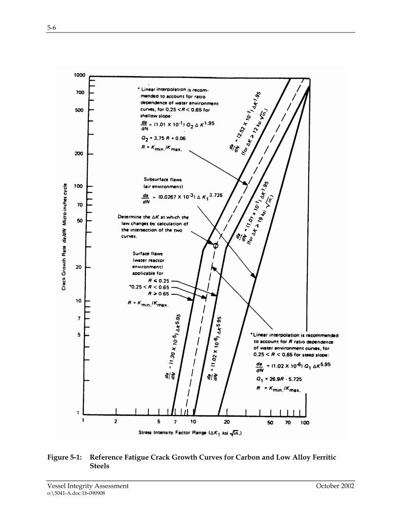
The crack growth was calculated using the ASME Section XI reference crack growth law for air environments, a law which has been contained in the ASME Code in its present form since 1979. This crack growth law is shown in Figure 5-1. The air environment curve was used because the cracks are all under the cladding, and not exposed to the PWR environment.
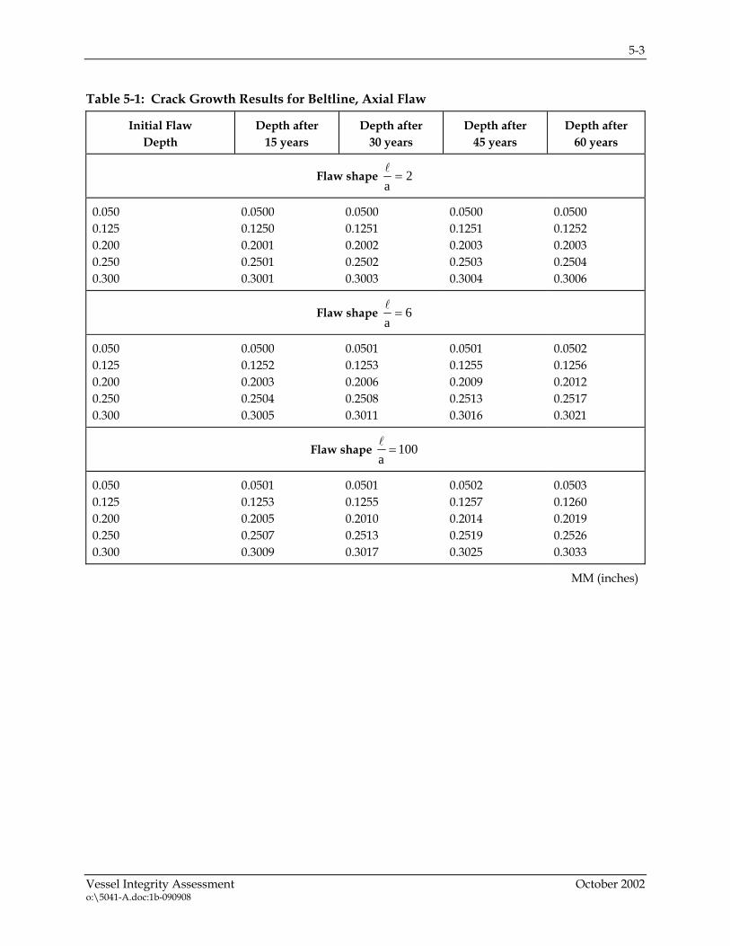
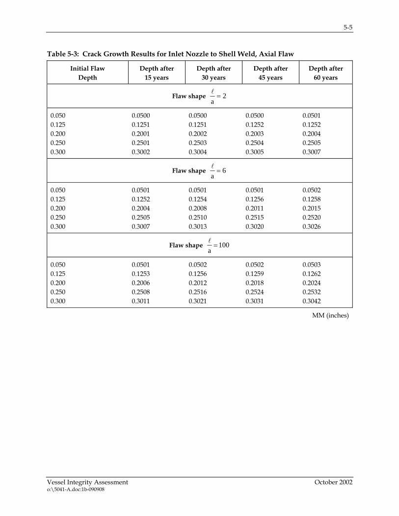
A series of flaw types were postulated to include the various possible shapes for the underclad cracks. Specifically, the postulated flaw depths ranged from 0.05 inch (1.3mm) to 0.30 inch (7.6mm), which is beyond the 0.295 inch (7.5mm) maximum depth of an underclad cold crack. The shape of the flaws analyzed (flaw depth/flaw length) ranged from 0.01 through 0.5. The results are shown in Tables 5-1 through 5-3, where it can be easily seen that the fatigue crack growth is extremely small, even over 60 years, regardless of the size, shape or orientation of the postulated flaws.
Therefore it may be concluded that the crack growth is insignificant for any type of flaw which might exist at the clad/base metal interface and into the base metal for both nozzle bore and vessel shell regions.
5.5 INSERVICE INSPECTIONS
Regular inservice inspections of the vessel will continue to provide a monitor for assessing the integrity of the vessel. The capability to detect and size near-surface indications such as these was significantly improved with the advent of Regulatory Guide 1.150, in the early 1980s. This same technology was used to meet the requirements of the Performance Demonstration Initiative for Section XI Appendix VIII Supplement 4. With the advent of a new set of USNRC regulations (10CFR50.55(a) effective November 22, 1999) which has adopted and modified the provisions of the ASME Code Section XI, Appendix VIII, inservice inspection methodologies of the vessel will continue to provide the capability for detection of flawed conditions and better characterization of any detected flaw indications.
5-3
Vessel Integrity Assessment October 2002 o:\5041-A.doc:1b-090908
Table 5-1: Crack Growth Results for Beltline, Axial Flaw
Initial Flaw Depth
Depth after 15 years
Depth after 30 years
Depth after 45 years
Depth after 60 years
Flaw shape 2a=
l
0.050 0.125 0.200 0.250 0.300
0.0500 0.1250 0.2001 0.2501 0.3001
0.0500 0.1251 0.2002 0.2502 0.3003
0.0500 0.1251 0.2003 0.2503 0.3004
0.0500 0.1252 0.2003 0.2504 0.3006
Flaw shape 6a=
l
0.050 0.125 0.200 0.250 0.300
0.0500 0.1252 0.2003 0.2504 0.3005
0.0501 0.1253 0.2006 0.2508 0.3011
0.0501 0.1255 0.2009 0.2513 0.3016
0.0502 0.1256 0.2012 0.2517 0.3021
Flaw shape 100a=
l
0.050 0.125 0.200 0.250 0.300
0.0501 0.1253 0.2005 0.2507 0.3009
0.0501 0.1255 0.2010 0.2513 0.3017
0.0502 0.1257 0.2014 0.2519 0.3025
0.0503 0.1260 0.2019 0.2526 0.3033
MM (inches)

5-4
Vessel Integrity Assessment October 2002 o:\5041-A.doc:1b-090908
Table 5-2: Crack Growth Results for Beltline, Circumferential Flaw
Initial Flaw Depth
Depth after 15 years
Depth after 30 years
Depth after 45 years
Depth after 60 years
Flaw shape 2a=
l
0.050 0.125 0.200 0.250 0.300
0.0500 0.1251 0.2002 0.2503 0.3003
0.0500 0.1252 0.2004 0.2505 0.3007
0.0501 0.1253 0.2006 0.2508 0.3010
0.0501 0.1254 0.2007 0.2510 0.3013
Flaw shape 6a=
l
0.050 0.125 0.200 0.250 0.300
0.0501 0.1254 0.2007 0.2510 0.3012
0.0502 0.1257 0.2014 0.2519 0.3024
0.0503 0.1260 0.2021 0.2528 0.3036
0.0504 0.1264 0.2028 0.2538 0.3049
Flaw shape 100a=
l
0.050 0.125 0.200 0.250 0.300
0.0501 0.1256 0.2011 0.2515 0.3020
0.0503 0.1261 0.2022 0.2531 0.3040
0.0504 0.1266 0.2033 0.2546 0.3060
0.0505 0.1272 0.2044 0.2561 0.3080
MM (inches)
5-5
Vessel Integrity Assessment October 2002 o:\5041-A.doc:1b-090908
Table 5-3: Crack Growth Results for Inlet Nozzle to Shell Weld, Axial Flaw
Initial Flaw Depth
Depth after 15 years
Depth after 30 years
Depth after 45 years
Depth after 60 years
Flaw shape 2a=
l
0.050 0.125 0.200 0.250 0.300
0.0500 0.1251 0.2001 0.2501 0.3002
0.0500 0.1251 0.2002 0.2503 0.3004
0.0500 0.1252 0.2003 0.2504 0.3005
0.0501 0.1252 0.2004 0.2505 0.3007
Flaw shape 6a=
l
0.050 0.125 0.200 0.250 0.300
0.0501 0.1252 0.2004 0.2505 0.3007
0.0501 0.1254 0.2008 0.2510 0.3013
0.0501 0.1256 0.2011 0.2515 0.3020
0.0502 0.1258 0.2015 0.2520 0.3026
Flaw shape 100a=
l
0.050 0.125 0.200 0.250 0.300
0.0501 0.1253 0.2006 0.2508 0.3011
0.0502 0.1256 0.2012 0.2516 0.3021
0.0502 0.1259 0.2018 0.2524 0.3031
0.0503 0.1262 0.2024 0.2532 0.3042
MM (inches)
5-6
Vessel Integrity Assessment October 2002 o:\5041-A.doc:1b-090908
Figure 5-1: Reference Fatigue Crack Growth Curves for Carbon and Low Alloy Ferritic
Steels

6-1
Summary and Conclusions October 2002 o:\5041-A.doc:1b-090908
6 SUMMARY AND CONCLUSIONS
In summary, a series of assessments have been completed and reported here to clearly show that there are many levels of defense in depth relative to the underclad cracks now known to exist.
There is no known mechanism for the creation of additional flaws in this region, so the only concern is the potential propagation of the existing flaws.
In 1971, Westinghouse submitted an assessment of the underclad reheat cracking issue [2] to the regulatory authorities, then the Atomic Energy Commission evaluating underclad cracks for an operating period of 40 years. The Commission reviewed the assessment, and issued the following conclusion:
SUMMARY OF REGULATORY POSITION:
“We concur with Westinghouse’s finding that the integrity of a vessel having flaws such as described in the subject report would not be compromised during the life of the plant. This report is acceptable and may be referenced in future applications where similar underclad grain boundary separations have been detected. However, such flaws should be avoided, and we recommend that future applicants state in their PSARs what steps they plan to take in this regard.”
Flaw indications indicative of underclad cracks have been evaluated in accordance with the acceptance criteria of the ASME Code Section XI. Such indications have been found during pre-service and inservice inspections of plants considered to have cladding conditions which are suspect with respect to underclad cracking. These flaw indications have been dispositioned as being acceptable for further service without repair or detailed evaluation, because they meet the conservative requirements of the ASME Code Section XI, Paragraph IWB 3500.
Fracture evaluations have also been performed to evaluate underclad cracks, and the results have always been that the flaws are acceptable. Concerns about residual stresses affecting these cracks have proven unfounded, because the cladding residual stress decreases as the temperature increases, reaching zero at about 400°F, as discussed in Section 4.
A number of field examples were summarized which have involved cladding cracks, as well as exposure of the base metal due to cladding removal. In several cases the cladding cracks have been suspected to extend into the base metal, and have been analyzed as such. In these cases the cracks were suspected to be exposed to the water environment, and successive monitoring inspections were conducted on the area of concern. No changes were found due to propagation or further deterioration of any type. The USNRC then allowed the surveillance to be discontinued.
Finally, to further document the conclusion that there is no structural integrity concern a fracture mechanics analysis of a series of postulated flaws was completed. The results show that little or no growth is expected, even for a period of 60 years. Therefore it may be concluded that underclad cracks in a reactor vessel are of no concern relative to the structural integrity of the vessel for continued plant operation, even through 60 years of operation.


7-1
References October 2002 o:\5041-A.doc:1b-090908
7 REFERENCES
1. Mager, T. R., Landerman, E. and Kubit, C. J., “Reactor Vessels Weld Cladding – Base Metal Interaction,” Westinghouse Electric WCAP-7673-L, April 1971.
2. Mager, T. R., Landerman, E., and Kubit, C. J., “Reactor Vessels Weld Cladding – Base Metal Interaction,” Westinghouse Electric WCAP-7733, July 1971.
3. Mager, T. R., Landerman, E., and Kubit, C. J., “Reactor Vessels Weld Cladding - Base Metal Interaction,” Westinghouse Electric WCAP-7673-L Addendum 1, August 1971.
4. U. S. Atomic Energy Commission letter, R. C. DeYong to R. Salvatori, “Topical Report Evaluation on Reactor Vessels, Weld Cladding – Base Metal Interaction” September 22, 1972.
5. Vinckier, A. G., and Pense, A. W., “A Review of Underclad Cracking in Pressure Vessel Components” Welding Research Bulletin 197, Welding Research Council, New York, NY, August 1974.
6. Rishel, R. D. and Bamford, W. H., “Evaluation of the Ultrasonic Test Results from the 1993 ISI on the Underclad Flaw Indications in the Sequoyah Unit 1 Reactor Vessel Nozzles,” Westinghouse Report MEM-MNA-296 (83) Rev. 2, July 13, 1993.
7. McCabe, D. E., “Fracture Evaluation of Surface Cracks Embedded in Reactor Vessel Cladding,” Report NUREG/CR-4841, May 1987.
8. McCabe, D. E., “Fracture Resistance of Irradiated Steel Clad Vessels,” in Effects of Radiation on Materials: 14th International Symposium, ASTM STP 1046, Philadelphia, PA 1990, pp. 348-360.
9. A. J. Bush and F. J. Kromer, “Simplification of the Hole-Drilling Method of Residual Stress Measurement,” ISA Transactions, Volume 12, No. 3, 1973, pp. 249-259.
10. “Standard Method for Determining Residual Stresses by the Hole-Drilling Strain-Gage Method,” ASTM E837, 1982.
11. J. E. Brynum, “Modifications to the Hole-Drilling Technique of Measuring Residual Stresses for Improved Accuracy and Reproducibility,” Experimental Mechanics, January 1981, pp. 21-33.
12. Ganta, B. R., Ayres, D. J. and Hijack, P. J., “Cladding Stresses in a Pressurized Water Reactor Vessel Following Application of the Stainless Steel Cladding, Heat Treatment and Initial Service,” ASME Pressure Vessel and Piping, Pressure Vessel Integrity, Vol. 213, pp. 245-252, 1991.

7-2
References October 2002 o:\5041-A.doc:1b-090908
13. McCabe, D. E., “Assessment of Metallurgical Effects that Impact Pressure Vessel Safe Margin Issues,” ORNL/NRC/LTR-94/26, October 1994.
14. Albertin, L., and Rao, G. V., “Metallurgical Investigation of the Offshore Power Company Reactor Vessel Outlet Nozzle Cracks,” Westinghouse Electric WCAP-9704, April 1980.
15. Adamonis, D. C., and Rishel, R. D., “Detection of Underclad Cold Cracking by Immersion Ultrasonic Techniques,” Westinghouse Electric WCAP-9980, September 1981.
16. Tome, R. E. and Caplan, J. S., “Summary of RV Vendor Nozzle Clad Practice Survey,” Westinghouse Electric Internal Letter PE-RVP-2806, November 19, 1979.
17. Rishel, R. D. and Adamonis, D. C., “Assessment of Ultrasonic Reflectors in the Watts Bar Unit II Reactor Vessel Nozzle Bores,” Westinghouse Electric Report, October 8, 1980.
18. Adamonis, D. C., and Rishel, R. D., “Ultrasonic Examination of Prairie Island Unit II Outlet Nozzle Bores for Detection of Underclad Cracking,” Westinghouse Electric Report MT-MNA-2822-81, June 4, 1981.
19. Mager, T. R., “Pre-Service Inspection Results - McGuire Unit II Reactor Vessel Nozzles Bores,” Westinghouse Electric Report MT-MNA-2398, October 30, 1980.
20. Adamonis, D. C., and Rishel, R. D., “Ultrasonic Examination of the Sequoyah Unit I Reactor Vessel Nozzles for Detection of Cracks Beneath the Stainless Steel Cladding,” Westinghouse Electric Report MT-MNA-947, February 18 & March 11, 1980.
21. Mager, T. R., “Pre-Service Inspection Results - Catawba Unit 1 Reactor Vessel Nozzle Bores,” Westinghouse Electric Report MT-MNA-2396, November 5, 1980.
22. Rishel, R. D., “Destructive Analysis of Four Indications Found in an Earlier Ultrasonic Examination of Reactor Vessel Nozzle Bores in Watts Bar Unit 1,” Westinghouse Electric Report MT-MNA-2577-81, February 3, 1981.
23. “Evaluation of Yankee Vessel Cladding Penetrations,” Westinghouse Electric Corp. WCAP 2855, October 15, 1965.
24. Bamford, W. H. et al., “Handbook on Flaw Evalaution for Hadam Neck Pressurizer Lower Head Region,” Westinghouse Electric WCAP 12653, July 1990.

8-1
Attachment, RAI Responses October 2002 o:\5041-A.doc:1b-090908
8 ATTACHMENT, RAI RESPONSES
OG-01-047, Revised Response to NRC Request for Additional Information on WCAP-15338, “A Review of Cracking Associated with Weld Deposited Cladding in Operating PWR Plants,” July 31, 2001.

8-2
Attachment, RAI Responses October 2002 o:\5041-A.doc:1b-090908
OG-01-047 NRC Project Number 686 July 31, 2001 To: Document Control Desk U.S. Nuclear Regulatory Commission Washington, DC 20555-0001 Attention: R.K. Anand, Project Manager License Renewal and Standardization Branch Division of Regulatory Improvement Programs Office of Nuclear Reactor Regulation Subject: Westinghouse Owners Group Revised Response to NRC Request for Additional Information on WCAP-15338,
“A Review of Cracking Associated with Weld Deposited Cladding in Operating PWR Plants,” (MUHP-6110)
References: 1. Request For Additional Information, Letter from R. K. Anand to R. A. Newton, April 12, 2001 2. OG-01-038, “Response to NRC Request for Additional Information on WCAP-15338, ‘A
Review of Cracking Associated with Weld Deposited Cladding in Operating PWR Plants, (MUHP6110),’ June 15, 2001,” to Document Control Desk, NRC
Attached is the Westinghouse Owners Group revised response to the NRC’s Request for Additional Information on the WOG Report WCAP-15388, “A Review of Cracking Associated with Weld Deposited Cladding in Operating PWR Plants,” March 2000. The revised text has been incorporated into the original response (Reference 2) and provides clarifications requested by the staff following their review of the original response. All new text is located in the first two paragraphs of the Introduction section, and is indicated by underscore. The requested reference for K solutions is: Newman, J.C. and Raju, I.S., "Stress Intensity Factors for Internal Surface cracks in Cylindrical Pressure Vessels", ASME Trans., Journal of Pressure Vessel Technology, Vol 102, 1980, pp342-346. Please distribute these responses to the appropriate people in your organization for their review It is the WOG understanding that a final safety evaluation be issued following acceptance of these revised responses.

8-3
Attachment, RAI Responses October 2002 o:\5041-A.doc:1b-090908
OG-01-047 July 31, 2001 If you have any questions regarding these responses, please contact Warren Bamford, Westinghouse, at (412) 374-6515, or Charlie Meyer, Westinghouse, at (412) 374-5027. Very truly yours, Signed Original on File in WOG Project Office Robert H. Bryan, Chairman Westinghouse Owners Group attachment

8-4
Attachment, RAI Responses October 2002 o:\5041-A.doc:1b-090908
OG-01-047 July 31, 2001 cc: R.K. Anand, Project Manager, USNRC License Renewal and Standardization Branch, (1L, 1A) C.I. Grimes, Director, USNRC License Renewal and Standardization Branch (1L, 1A) Westinghouse Owners Group Primary Representatives (1L, 1A) Westinghouse Owners Group LCM/LR Working Group (1L, 1A) Westinghouse Owners Group Steering Committee (1L, 1A) A.P. Drake, W ECE 5-16 (1L, 1A) C.E. Meyer, W ECE 4-07 (1L, 1A) W.H. Bamford, WECE 314C (1L, 1A)

8-5
Attachment, RAI Responses October 2002 o:\5041-A.doc:1b-090908
OG-01-047 bcc: S.A. Binger ECE 5-16 (1L, 1A) P.V. Pyle ECE 5-16 (1L, 1A) K.J. Vavrek ECE 5-16 (1L) S.R. Bemis ECE 5-16 (1L, 1A) P. Richardson CEOG Windsor

8-6
Attachment, RAI Responses October 2002 o:\5041-A.doc:1b-090908
NRC Request for Additional Information Regarding the Review of WCAP-15338
Questions Regarding Vessel Integrity Assessment
Underclad cracks were first discovered in October 1970 during examination of the Atucha reactor vessel. They have been reported to exist only in SA-508 Class 2 reactor vessel forgings manufactured to a coarse grain practice and clad by high-heat-input submerged arc process. The analysis documented in WCAP-15338 evaluates the fatigue crack growth of underclad cracks during 60 years of operation. The analysis documented in WCAP-15338 assumes that fabrication cracks beneath the clad will not penetrate the clad and that the fatigue crack growth could be projected using the ASME Code Section XI reference crack growth law for air environment.
1) Since it can not be ensured that the cracks will not penetrate the clad, the fatigue crack growth evaluation should be performed using the ASME Code Section XI reference crack growth law for water reactor environment. The postulated surface flaw should have an aspect ratio of 6:1 and its depth should include the clad thickness and bound the size of flaws observed during fabrication. Does the 0.295 inch crack depth discussed in the report represent the bounding size of flaw observed during fabrication or does it include the clad thickness?
2) To evaluate reactor pressure vessel integrity:
a) The projected flaw length at the end of the license renewal period should be evaluated to the criteria in ASME Code Section XI, Paragraph IWB-3600. The fracture mechanics evaluation should include: (1) all forging materials that were susceptible to the under clad cracking (i.e. beltline, nozzle belt, vessel flange etc.), (2) embrittlement of beltline forgings at the end of the license renewal term, (3) cladding effects, (4) axial and circumferential flaw configurations, and (5) normal/upset and emergency/faulted conditions.
b) The projected flaw length at the end of the license renewal period should be evaluated to demonstrate that the beltline forgings are not susceptible to pressurized thermal shock (PTS) during the license renewal term. The fracture mechanics analysis should be performed using the worst transient from the PTS study of 1982 (the extended HPI transient) a pressure of 2250 psi, and the embrittlement projected for the limiting beltline forging at the end of the license renewal period.

8-7
Attachment, RAI Responses October 2002 o:\5041-A.doc:1b-090908
WOG Revised Responses to NRC Questions Regarding Vessel Integrity Assessment
NOTE: The revised responses have been written in the form of an appendix to the original report, WCAP-15338.
Appendix A ASME Code Section XI Flaw Evaluation
A-1 Introduction
To ensure that any underclad cracks are acceptable for service, an ASME Code Section XI flaw evaluation was carried out. The assumed initial flaw depth for the evaluation corresponded to the maximum depth of any underclad flaw observed, as discussed in the main body of this report. The flaw depth assumed was 0.295 inches. This depth was conservatively assumed to be in the base metal only, and does not include the clad thickness. The flaw evaluation did NOT assume the crack to be through the clad as well, because no such cases have ever been observed. The fatigue crack growth did, however, assume that the flaw was exposed to the water environment.
The evaluation detailed here is for a typical plant, and is expected to apply to any Westinghouse operating plant for an operating period of at least 60 years. The Emergency and Faulted conditions fracture results are also for a typical plant, but plant specific treatment of Pressurized Thermal Shock events are covered through each plant’s compliance with the screening criteria of 10CFR50.61. An ambitious industry/NRC program is now underway, and is expected to confirm the conservatism of these screening criteria.
This section begins with the acceptance criteria per paragraph IWB-3600 of ASME Code Section XI, which is followed by the fatigue crack growth and allowable flaw size calculations.
A-2 Acceptance Criteria
There are two alternative sets of flaw acceptance criteria for ferritic components, for continued service without repair in paragraph IWB-3600 of ASME Code Section XI. Either of the criteria below may be used, at the convenience of the user.
1. Acceptance Criteria Based on Flaw Size (IWB-3611)
2. Acceptance Criteria Based on Stress Intensity Factor (IWB-3612)
Both criteria are comparable for thick sections, and the acceptance criteria based on stress intensity factor have been determined by past experience to be less restrictive for thin sections, and for outside surface flaws in many cases. In all cases, the most beneficial criteria have been used in the evaluation to be presented here.
A-2.1 Criteria Based on Flaw Size
The code acceptance criteria stated in IWB-3611 of Section XI for ferritic steel components 4 inch and greater in wall thickness are:
af < .1 ac For Normal Conditions
8-8
Attachment, RAI Responses October 2002 o:\5041-A.doc:1b-090908
(Upset & Test Conditions inclusive)
and af < .5 ai For Faulted Conditions (Emergency Condition inclusive)
where
af = The maximum size to which the detected flaw is calculated to grow until the next inspection. 15, 30, 45, and 60 year periods have been considered.
ac = The minimum critical flaw size under normal operating conditions (upset and test conditions inclusive).
ai = The minimum critical flaw size for initiation of nonarresting growth under postulated faulted conditions (emergency conditions inclusive).
A-2.2 Criteria Based on Applied Stress Intensity Factors
Alternatively, the code acceptance criteria stated in IWB-3612 of Section XI for ferritic steel components criteria based on applied stress intensity factors may be used:
10
K<K IaI For normal conditions (upset & test conditions inclusive)
2K<K Ic
I For faulted conditions (emergency conditions inclusive)
where
KI = The maximum applied stress intensity factor for the final flaw size after crack growth, using 15, 30, 45, and 60 year periods.
KIa = Fracture toughness based on crack arrest for the corresponding crack tip temperature.
KIc = Fracture toughness based on fracture initiation for the corresponding crack tip temperature.
A-3 Fatigue Crack Growth
A series of fatigue crack growth calculations was performed to provide a prediction of future growth of unclad cracks for service periods up through 60 years. This is similar to the work carried out in Section 5.4 of this report, however, the crack growth law for water environment was used here for conservatism. The crack growth rate curves used in the analyses were taken directly from Appendix A of Section XI of the ASME Code.
For water environments the reference crack growth curves are shown in Figure 5-1, and growth rate is a

8-9
Attachment, RAI Responses October 2002 o:\5041-A.doc:1b-090908
function of both the applied stress intensity factor range, and the R ratio (Kmin/Kmax) for the transient.
For R ≤ 0.25
( ) ( ) 95.5I
6I K10x02.1
dNda,inksi19K Δ=<Δ −
( ) ( ) 95.1I
3I K10x01.1
dNda,inksi19K Δ=>Δ −
where dNda = Crack Growth rate, micro-inches/cycle.
For R ≥ 0.65
( ) ( ) 95.5I
5I K10x20.1
dNda,inksi12K Δ=<Δ −
( ) ( ) 95.1I
1I K10x52.2
dNda,inksi12K Δ=>Δ −
For R ratio between these two extremes, interpolation is recommended. The crack growth evaluation was performed for surface flaws in the beltline region of a generic Westinghouse 3-loop reactor vessel. The results are shown in Tables A-3.1 and A-3.2 for postulated axial and circumferential flaw depths ranging from 0.05 inch (1.3mm) to 0.30 inch (7.6mm), which is beyond the 0.295 inch (7.5mm) maximum depth of an underclad cold crack as discussed in Section 2 of the main body of this report. Note that the final flaw depths (af’s) for the water environment are slightly higher than those presented in Tables 5-1 and 5-2 for air environment.

8-10
Attachment, RAI Responses October 2002 o:\5041-A.doc:1b-090908
Table A-3.1: Crack Growth Results for Beltline Region, Axial Flaw (Water Environment)
Initial Flaw Depth after Depth after Depth after Depth after
Depth (in.) 15 years 30 years 45 years 60 years
0.050 0.0500 0.0500 0.0500 0.0501
0.125 0.1252 0.1255 0.1257 0.12590.200 0.2009 0.2018 0.2027 0.2036
0.250 0.2517 0.2534 0.2550 0.2568
0.300 0.3028 0.3056 0.3084 0.3113
0.050 0.0502 0.0504 0.0506 0.0508
0.125 0.128 0.1311 0.1343 0.13790.200 0.2071 0.2143 0.2219 0.2302
0.250 0.26 0.2699 0.2799 0.2907
0.300 0.3122 0.3244 0.337 0.3505
0.050 0.0505 0.0509 0.0514 0.0519
0.125 0.1303 0.1357 0.1415 0.1479
0.200 0.2114 0.2231 0.2354 0.2490.250 0.2656 0.2817 0.2989 0.3181
0.300 0.3202 0.3413 0.3639 0.3891
Flaw shape l/a = 2
Flaw shape l/a = 6
Continuous Flaw
Note: Aspect Ratio l/a = flaw length / flaw depth

8-11
Attachment, RAI Responses October 2002 o:\5041-A.doc:1b-090908
Table A-3.2: Crack Growth Results for Beltline Region, Circumferential Flaw (Water Environment)
Initial Flaw Depth after Depth after Depth after Depth after Depth (in.) 15 years 30 years 45 years 60 years
0.050 0.0500 0.0500 0.0500 0.05000.125 0.1250 0.1250 0.1251 0.12510.200 0.2001 0.2001 0.2002 0.20030.250 0.2501 0.2502 0.2504 0.25050.300 0.3002 0.3004 0.3006 0.3008
0.050 0.05 0.05 0.0501 0.05010.125 0.1253 0.1255 0.1258 0.1260.200 0.201 0.2019 0.2028 0.20370.250 0.2517 0.2533 0.255 0.25670.300 0.3027 0.3053 0.3079 0.3107
0.050 0.05 0.0501 0.0501 0.05020.125 0.1256 0.1262 0.1268 0.12740.200 0.2022 0.2044 0.2066 0.20890.250 0.2539 0.2577 0.2616 0.26580.300 0.3062 0.3123 0.3186 0.3252
Flaw shape l/a = 2
Flaw shape l/a = 6
Continuous Flaw
Note: Aspect Ratio l/a = flaw length / flaw depth

8-12
Attachment, RAI Responses October 2002 o:\5041-A.doc:1b-090908
A-4 Allowable Flaw Size Determination – Normal, Upset & Test Conditions
The allowable flaw size for normal, upset and test conditions was calculated using the criteria in Section A-2.2. The fracture toughness for ferritic steels has been taken directly from the reference curves of Appendix A, Section XI. In the transition temperature region, these curves can be represented by the following equations:
KIc = 33.2 + 2.806 exp. [0.02 (T-RTNDT + 100°F)]
KIa = 26.8 + 1.233 exp. [0.0145 (T-RTNDT + 160°F)]
where KIc and KIa are in inksi .
The upper shelf temperature regime requires utilization of a shelf toughness, which is not specified in the ASME Code. A value of 200 inksi has been used here. This value is consistent with general practice in such evaluations.
The minimum allowable flaw size was calculated using the most governing transients under normal operating conditions for the location of interest. To select the most governing transients for the beltline region, the stress intensity factors (KI) for several normal, upset and test conditions were calculated for axial flaws in the beltline region. The axial flaws were chosen since the hoop stresses are higher than the axial stresses in the beltline region, as can be evident from the crack growth results in Tables A-3.1 and A-3.2. The stress intensity factors are plotted in Figures A-4.1 through A-4.3 for three different flaw shapes. Note that several transients were considered for each flaw shape, to ensure that the most governing transient would be chosen. The allowable flaw depth was chosen as the intersection of the stress intensity factor curve with the allowable fracture toughness, which is inksi2.6310/200 = . The minimum allowable flaw size results for normal, upset and test conditions are provided below:
Table A-4.1: Allowable Flaw Size Summary For Beltline Region – Normal, Upset & Test Conditions
Flaw Shape Governing Transient
inches (a/t)
Aspect Ratio 2:1 Inadvertent Safety Injection 4.07 (0.525)
Aspect Ratio 6:1 Reactor Trip with Cooldown and S.I. 1.34 (0.173)
Continuous Flaw Excessive Feedwater Flow 0.67 (0.086)
Allowable Flaw Size
Note: Wall Thickness = 7.75” is used here.

8-13
Attachment, RAI Responses October 2002 o:\5041-A.doc:1b-090908
Figure A-4.1 Allowable Flaw Size Determination – Beltline Region, Axial Flaw, AR 2:1
0
10
20
30
40
50
60
70
80
90
0 0.1 0.2 0.3 0.4 0.5 0.6 0.7 0.8
Crack Depth to Wall Thickness Ratio (a/t)
Stre
ss In
tens
ity F
acto
r K, k
si s
qrt(i
n)HU/CD Feedwater Cycling Reactor Trip w/SI Inadvertent Depress. Inadvertent SI Excessive Feedwater

8-14
Attachment, RAI Responses October 2002 o:\5041-A.doc:1b-090908
Figure A-4.2 Allowable Flaw Size Determination – Beltline Region, Axial Flaw, AR 6:1
0
20
40
60
80
100
120
140
160
180
200
0 0.1 0.2 0.3 0.4 0.5 0.6 0.7 0.8
Crack Depth to Wall Thickness Ratio (a/t)
Stre
ss In
tens
ity F
acto
r K, k
si s
qrt(i
n)HU/CD Feedwater Cycling Reactor Trip w/SI Inadvertent Depress. Inadvertent SI Excessive Feedwater
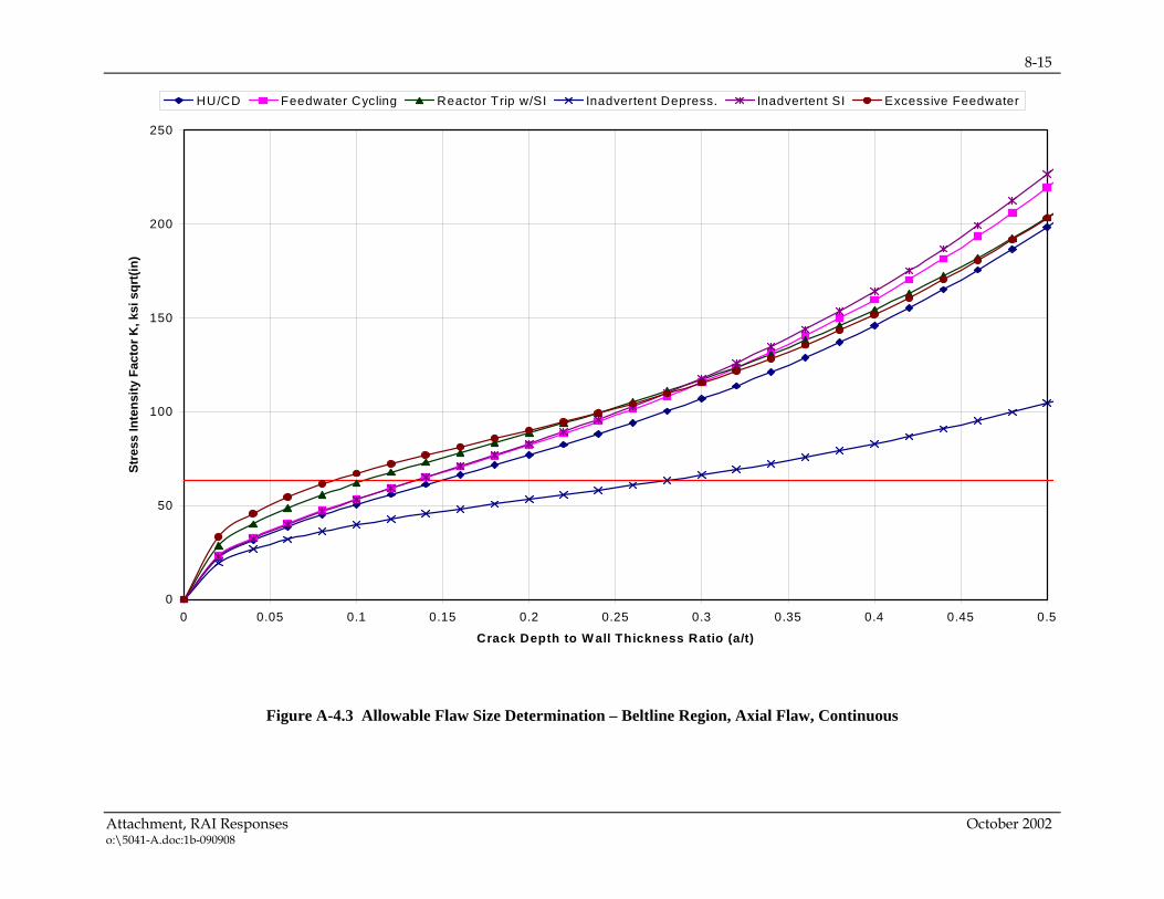
8-15
Attachment, RAI Responses October 2002 o:\5041-A.doc:1b-090908
Figure A-4.3 Allowable Flaw Size Determination – Beltline Region, Axial Flaw, Continuous
0
50
100
150
200
250
0 0.05 0.1 0.15 0.2 0.25 0.3 0.35 0.4 0.45 0.5
Crack Depth to W all Thickness Ratio (a/t)
Stre
ss In
tens
ity F
acto
r K, k
si s
qrt(i
n)
HU/CD Feedwater Cycling Reactor Trip w/SI Inadvertent Depress. Inadvertent SI Excessive Feedwater

8-16
Attachment, RAI Responses October 2002 o:\5041-A.doc:1b-090908
A-5 Allowable Flaw Size Determination –Emergency & Faulted Conditions The selection of the governing transient for emergency and faulted conditions was not as straightforward as the selection for normal, upset and test conditions, primarily due to the pressurized thermal shock (PTS) issue. This issue had previously resulted in an extensive probabilistic risk assessment study by Westinghouse Owners’ Group (WOG) to identify the overall risk from PTS on a typical Westinghouse plant. The study included all transients that could potentially result in a pressurized thermal shock of the reactor vessel. The summary of the WOG risk assessment for PTS showed that the key contributors to the total risk occur from small LOCA and steam generator tube rupture (SGTR), because of the combination of severe transient characteristics with relatively high frequencies of transient occurrence. The ASME Code in its present form, however, does not take transient frequencies into consideration and requires an evaluation of flaw indications using the most limiting emergency/faulted condition transient. Therefore, the WOG PTS risk analysis results could not be used directly, but they were used to guide the determination of the key transients to be considered here. To determine the governing emergency and faulted conditions for a generic Westinghouse 3-loop reactor vessel, a series of transients were studied. These transients included the large LOCA and large steamline break (LSB) and the dominating transients from the WOG pressurized thermal shock studies. This work led to the conclusion that the following transients should be considered in the deterministic assessments for the beltline region:
• Steam Generator Tube Rupture (SGTR) • Small LOCA • Large LOCA • Large Steamline Break (LSB)
Thermal stress and fracture analyses were performed for the beltline region, utilizing the characteristics of the above four transients. The limiting circumferential and axial flaws were used in performing the fracture analyses. The resulting critical flaw depths for a range of shapes are shown in Table A-5.1. From Table A-5.1, it may be seen that the large steamline break transient is the governing transient for the beltline region. The detailed assessments performed for the tube rupture and small LOCA transients serve to verify this conclusion. Also, from the standpoint of total risk, it is worthy of note that these latter two transients are the dominant ones. Section XI of the ASME Code presently requires that only the most severe transient be evaluated, regardless of its probability of occurrence, so the large steamline break is the governing transient for the beltline region. Therefore, using the criteria in Section A-2.1, the minimum allowable flaw size for emergency and faulted conditions is summarized in Table A-5.2, for axial flaws.
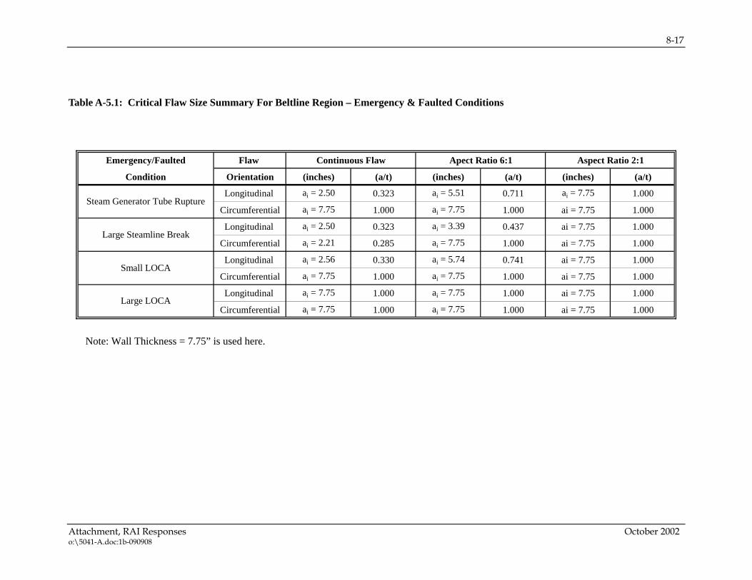
8-17
Attachment, RAI Responses October 2002 o:\5041-A.doc:1b-090908
Table A-5.1: Critical Flaw Size Summary For Beltline Region – Emergency & Faulted Conditions
Emergency/Faulted Flaw
Condition Orientation (inches) (a/t) (inches) (a/t) (inches) (a/t)
Longitudinal ai = 2.50 0.323 ai = 5.51 0.711 ai = 7.75 1.000
Circumferential ai = 7.75 1.000 ai = 7.75 1.000 ai = 7.75 1.000
Longitudinal ai = 2.50 0.323 ai = 3.39 0.437 ai = 7.75 1.000
Circumferential ai = 2.21 0.285 ai = 7.75 1.000 ai = 7.75 1.000
Longitudinal ai = 2.56 0.330 ai = 5.74 0.741 ai = 7.75 1.000
Circumferential ai = 7.75 1.000 ai = 7.75 1.000 ai = 7.75 1.000
Longitudinal ai = 7.75 1.000 ai = 7.75 1.000 ai = 7.75 1.000
Circumferential ai = 7.75 1.000 ai = 7.75 1.000 ai = 7.75 1.000
Large Steamline Break
Steam Generator Tube Rupture
Small LOCA
Large LOCA
Continuous Flaw Apect Ratio 6:1 Aspect Ratio 2:1
Note: Wall Thickness = 7.75” is used here.

8-18
Attachment, RAI Responses October 2002 o:\5041-A.doc:1b-090908
Table A-5.2: Allowable Axial Flaw Size Summary For Beltline Region – Emergency and Faulted Conditions
Flaw Shape
inches (a/t)
Aspect Ratio 2:1 3.88 (0.501)
Aspect Ratio 6:1 1.70 (0.219)
Continuous Flaw 1.25 (0.162)
Allowable Flaw Size
Note: Wall Thickness = 7.75” is used here. A-6 Summary and Conclusions Underclad cracks found during pre-service and inservice inspections have been evaluated in accordance with the acceptance criteria of the ASME Code Section XI. Underclad cracks are very shallow, confined in depth to less than 0.295 inch and have lengths up to 2.0 inches. The fatigue crack growth assessment for these small cracks shows very little extension over 60 years, even if they were exposed to the reactor water. For the worst case scenario, a 0.30 inch deep continuous axial flaw in the beltline region would grow to 0.39 inch after 60 years. The minimum allowable axial flaw size for normal, upset and test conditions is 0.67 inch and for emergency and faulted conditions is 1.25 inches. Since the allowable flaw depths far exceed the maximum flaw depth after 60 years of fatigue crack growth, we may conclude that underclad cracks of any shape are acceptable for service for 60 years, regardless of the size or orientation of the flaws. Therefore, it may be concluded that undeclad cracks are of no concern relative to structural integrity of the reactor vessel for a period of 60 years.

9-1
Attachment, WOG Letters October 2002 o:\5041-A.doc:1b-090908
9 ATTACHMENT, WOG LETTERS
OG-02-024, “Information Supporting WOG Request for Modification of NRC Safety Evaluation Report on WCAP-15338, A Review of Cracking Associated with Weld Deposited Cladding in Operating PWR Plants,” June 19, 2002.
WOG-01-096, “Transmittal of LR Phase 2 Program Generic Issues 107, Approved Responses,” April 16, 2001. [Cover letter and Generic Issue #4, Reactor Vessel Underclad Cracking, only.] This information was NOT submitted to the NRC for review and is NOT considered in the conclusions presented in the SER.

9-2
Attachment, WOG Letters October 2002 o:\5041-A.doc:1b-090908
9-3
Attachment, WOG Letters October 2002 o:\5041-A.doc:1b-090908

9-4
Attachment, WOG Letters October 2002 o:\5041-A.doc:1b-090908

9-5
Attachment, WOG Letters October 2002 o:\5041-A.doc:1b-090908

9-6
Attachment, WOG Letters October 2002 o:\5041-A.doc:1b-090908

9-7
Attachment, WOG Letters October 2002 o:\5041-A.doc:1b-090908
9-8
Attachment, WOG Letters October 2002 o:\5041-A.doc:1b-090908

9-9
Attachment, WOG Letters October 2002 o:\5041-A.doc:1b-090908

9-10
Attachment, WOG Letters October 2002 o:\5041-A.doc:1b-090908
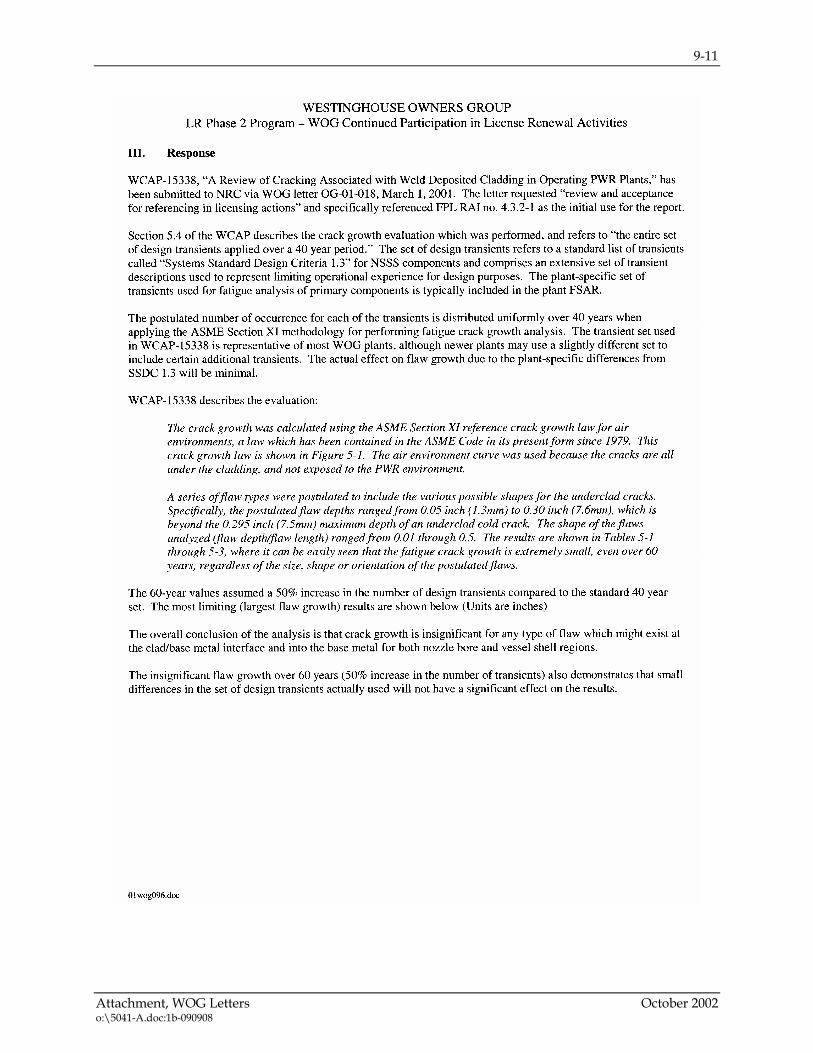
9-11
Attachment, WOG Letters October 2002 o:\5041-A.doc:1b-090908

9-12
Attachment, WOG Letters October 2002 o:\5041-A.doc:1b-090908


