This report was prepared by Westinghouse Electric Company LLC as an account of worksponsored by the Westinghouse Owners Group (WOG). Neither the WOG nor any member of theWOG, Westinghouse or any person acting on behalf of them:
A. Makes any warranty or representation, express or implied including the warranties offitness for a particular purpose or merchantability, with respect to the accuracy,completeness, or usefulness of the information contained in this report, or that the useof any information, apparatus, method, or process disclosed in this report may notinfringe privately owned rights; or
B. Assumes any liabilities with respect to the use of, or for damages resulting from the useof, any information, apparatus, method, or process disclosed in this report.
Reactor Coolant System Design & Analysis - CE Fleet
Reviewer: D 1 0 . a t
Steam Generator Design and Analysis
Approved: /tzj 4awl\ S d•(E. A. Siegel, Ma geiVReactor Coolant System Design & Analysis - CE Fleet
0 2004 Westinghouse Electric Company LLC20 International Drive, PO Box 500
Windsor, CT 06095-0500
All Rights Reserved
COPYRIGHT NOTICE
This report has been prepared by Westinghouse Electric Company LLC, for themembers of the Owners Group participating in this Group Task. Information in thisreport is the property of and contains copyright material owned by WestinghouseElectric Company LLC and /or its subcontractors and suppliers. It is transmitted toyou in confidence and trust, and you agree to treat this document and the materialcontained therein in strict accordance with the terms and conditions of the agreementunder which it was provided to you.
As a participating member of this Owners Group task, you are permitted to make thenumber of copies of the information contained in this report that are necessary foryour internal use in connection with your implementation of the report results foryour plant(s) in your normal conduct of business. Should implementation of thisreport involve a third party, you are permitted to make the number of copies of theinformation contained in this report that are necessary for the third party's use insupporting your implementation at your plant(s) in your normal conduct of business ifyou have received the prior, written consent of Westinghouse Electric Company LLCto transmit this information to a third party or parties. All copies made by you mustinclude the copyright notice in all instances.
The NRC is permitted to make the number of copies beyond those necessary for itsinternal use that are necessary in order to have one copy available for public viewingin the appropriate docket files in the NRC public document room in Washington, DCif the number of copies submitted is insufficient for this purpose. Copies made by theNRC must include the copyright notice in all instances.
iii
TABLE OF CONTENTS
TABLE OF CONTENTS ............................. iii
LIST OF TABLES ........................... iv
LIST OF FIGURES ........................... iv
ACRONYMS AND ABBREVIATIONS ............................ v
EXECUTIVE SUMMARY ........................... vii
I INTRODUCTION . 1-1
1.1 PURPOSE .1-11.2 BACKGROUND. 1-I1.3 ALLOY 600 PROGRAM 1.-
2 CARBON AND LOW-ALLOY STEEL BORATED WATER CORROSION .2-1
2.1 GENERAL .2-2.2 LABORATORY CORROSION DATA .2-12.3 CORROSION RATE EVALUATION .2-42.3.1 CORROSION RATE EVALUATION .2-52.3.2 INTERMEDIATE TEMPERATURE CORROSION RATE .2-62.3.3 LOW TEMPERATURE CORROSION RATE .2-62.3.4 OVERALL CORROSION RATE .2-62.4 ESTIMATE OF REPAIR LIFETIME .2-62.5 ALTERNATE ESTIMATE OF CARBON AND LOW ALLOY STEEL
CORROSION .2-92.6 FIELD EXPERIENCE WITH HALF-NOZZLE REPAIRS .2-10
3 CARBON AND LOW ALLOY STEEL CRACK GROWTH EVALUATION .3-1
3.1 GENERAL .3-13.2 ASSESSMENT OF THE RESIDUAL STRESS DISTRIBUTION .3-13.3 CALCULATION OF THE STRESS INTENSITY FACTOR, K . 3-33.4 FATIGUE CRACK GROWTH .3-53.5 FINAL CRACK STABILITY COMPARISONS .3-73.6 STRESS CORROSION CRACKING ASSESSMENT .3-93.6.1 ENVIRONMENTAL FACTORS .3-93.6.2 MATERIAL FACTORS .3-113.6.3 STRESS INTENSITY EFFECTS .3-113.6.4 FIELD EXPERIENCE .3-11
Appendix A: Response to Request forAdditional Informnation .............................................. A-I
WCAP-15973-NP, Rev 01 May 2004
iv
LIST OF TABLES
Table 2-1 Summary of A302B Corrosion Data ......................................... 2-11
Table 2-2 Corrosion Test Results ......................................... 2-12
LIST OF FIGURES
Figure 1-1 Schematic Diagram of a Half-Nozzle Repair ......................................... 1-4
Figure 1-2 Diagram of a Mechanical Nozzle Seal Assembly (MNSA) ......................................... 1-5
Figure 3-1 Influence of Oxygen and Temperature on Corrosion Potential of Low Alloy Steels inHigh Temperature Water . 3-13
Figure 3-2 Effects of Potential Upon the Reduction in Area to Fracture at Various Temperaturesin Slow Strain Rate Tests . 3-14
WCAP-15973-NP, Rev 01 May2004WCAP- I5973-NP, Rev 0 May 2004
V
ACRONYMS AND ABBREVIATIONS
ANO Arkansas Nuclear One
ASME American Society of Mechanical Engineers
BWR Boiling Water Reactor
CE Combustion Engineering
CEOG CE Owners Group
CR Corrosion Rate
ID Inside Diameter
IN Increase in Diameter
K1 Stress Intensity Factor
MNSA Mechanical Nozzle Seal Assembly
OBE Operating Basis Earthquake
OD Outside Diameter
PWR Pressurized Water Reactor
PWSCC Primary Water Stress Corrosion Cracking
RTD Resistance temperature Detector
SCC Stress Corrosion Cracking
SSE Safe Shutdown Earthquake
UT Ultrasonic Test
WOG Westinghouse Owners Group
�VCAP-15 973-NP, Rev 01 May2004WCAP-15973-NP, Rev 01 May 2004
vi
This page intentionally blank.
WCAP-15973-NP, Rev 01 May2004WCAP-1 5973-NP, Rev 0 1 May 2004
vii
EXECUTIVE SUMMARY
Small-diameter NiCrFe Alloy 600 nozzles, such as hot leg piping RTD and sampling nozzles, pressurizerinstrumentation nozzles, and pressurizer heater sleeves in CE Nuclear Power designed pressurized waterreactors have developed leaks or partial through-wall cracks as a result of primary water stress corrosioncracking. The residual stresses imposed by the partial-penetration welds between the nozzles and the lowalloy or carbon steel components are sufficient to cause crack initiation and propagation.
Two techniques, the "half-nozzle" weld repair and the mechanical nozzle seal assembly (MNSA) arecurrently used to repair or replace leaking Alloy 600 nozzles, and as preventive repairs on nozzles thatmay leak in the fuiture. In the "half-nozzle" technique, the Alloy 600 nozzle is cut outboard of the partial-penetration weld and replaced with a short Alloy 690 nozzle section that is welded to the componentoutside surface. Mechanical nozzle seal assemblies are installed to mechanically seal a leaking nozzle atthe outer surface of the component. In either technique, the crevices between the nozzles and componentswill fill with primary coolant and the flaws that resulted in primary coolant leakage will remain, althoughleakage will no longer be possible. This report evaluates the effect of component corrosion resulting fromprimary coolant in the crevice region on component integrity and evaluates the effects of propagation ofthe flaws left in place by fatigue crack growth and stress corrosion cracking mechanisms.
This revised report was prepared to correct errors in the calculations supporting the original report and toincorporate conditions not included in the calculations supporting the original report. An error in theprogram for calculating fatigue crack growth has been corrected and all crack growth analyses have beenrepeated. The stress analyses and fracture mechanics evaluations supporting the original report did notinclude the effects of the pressurizer support skirt. The support skirt effects were incorporated into thestress and fracture mechanics analyses of the pressurizer lower head. Similarly, the original calculationsdid not address the effect of periodic insurges of coolant on the pressurizer lower head. Previous workindicates that such insurges can and do occur during plant heat-ups and cool-downs. The heat-up/cool-down transients have been modified to include insurges and the fatigue crack growth calculationsrepeated.
This revised report provides bounding analyses for the maximum material degradation estimated to resultfrom corrosion of the carbon or low alloy steel in the crevices between the nozzles and components.Results show that the quantity of material lost does not exceed ASME code limits. The report alsoprovide results of fatigue crack growth evaluations and crack stability analyses for pressurizer heatersleeves and instrument nozzles and hot leg pipe nozzles, including the effects of the support skirt andpressurizer in-surges. The revised results indicate that the ASME Code acceptance criteria for crackgrowth and crack stability are met. Further, available laboratory data and field experience indicate thatcontinued propagation of cracks into the carbon and low alloy steels by a stress corrosion mechanism isunlikely.
Half-nozzle replacement and mechanical nozzle seal assemblies are shown to be effectiverepair/replacement methods for leaking small-diameter nozzles from a corrosion, stress corrosion andfatigue crack growth assessment perspective. Corrosion of carbon and low alloy steels will be withinCode limits and it is acceptable to leave a flaw in place in small diameter Alloy 600 nozzles and partialpenetration welds for the balance of plant life.
WCAP-15973-NP, Rev 01 May 2004WCAP-15973-NP, Rev 01 May 2004
viii
This page intentionally blank.
�VCAP-I5973-NP, Rev 01 May2004IVCAP-15973-NP, Rev 01 May 2004
1-1
1 INTRODUCTION
1.1 PURPOSE
The purpose of this revised report is to demonstrate that unacceptable degradation of carbon or low alloysteel (base metal) does not occur when small diameter NiCrFe Alloy 600 nozzles in the primary pressureboundary of Combustion Engineering (CE) plants are repaired/replaced using the "half-nozzle" repairtechnique or mechanical seal nozzle assemblies (MNSAs). In these repairs, the carbon and low alloy steelbase metals in the piping and pressurizers, which are normally clad with corrosion resistant materials, areleft exposed to primary coolant. In addition, the original flaw which caused the leakage will be left inplace and will continue to be subjected to stresses and temperature which could continue to propagate theflaws into the carbon and low alloy steel component material. The types of degradation evaluated in thisreport include general corrosion from exposure to primary coolant, stress corrosion cracking, and fatiguecrack growth.
Subsequent to completion of the calculations supporting the original report, an error was discovered in theprogram used for determining crack propagation. Also, the original stress and fracture mechanicsanalyses did not consider the effects of the pressurizer support skirt, which resulted in the underprediction of stresses. Further, the transients evaluated in the original report did not include the effects ofpressurizer insurges that can and do occur during plant heat-ups and cool-downs. As a result, thecalculations were repeated. This revised report presents the results of the new calculations and assessestheir effects on fatigue crack growth and crack stability.
1.2 BACKGROUND
Primary water stress corrosion cracking (PWSCC) of Alloy 600 nozzles in CE plants first occurred in1986 when a leaking pressurizer instrument nozzle was discovered at San Onofre-3. Most of the CEplants have experienced nozzle or heater sleeve leaks since 1986. The first leaks in Alloy 600 nozzleswere in pressurizer instrument nozzles and heater sleeves where operating temperatures are the highest(Reference l). This was expected since laboratory testing indicated that primary water stress corrosioncracking (PWSCC) is temperature dependent. Later, leaking or cracked nozzles were discovered atseveral plants in hot leg piping applications where temperatures are lower.
1.3 ALLOY 600 PROGRAM
There are several applications of small diameter NiCrFe Alloy 600 nozzles within the primary coolantpressure boundaries of CE PWRs. These applications include pressurizer instrumentation nozzles andheater sleeves, piping RTD and sampling nozzles, steam generator instrumentation nozzles, and reactorvessel head vent lines and leakage monitor tubes. Alloy 600 nozzle materials were procured as eitherpipe (ASME SB-167) for the heater sleeves, vent lines and leakage monitor tubes, or as bar stock (ASMESB-166) for all other nozzles. References 2 and 3 present the available materials properties andinstallation data for all nozzle applications of Alloy 600 in CE designed PWRs.
The Combustion Engineering Owners Group (CEOG) initiated an Alloy 600 program after the discoveryof leaking pressurizer heater sleeves and a pressurizer instrumentation nozzle at Calvert Cliffs-2 in 1989.The objectives of this program were to identify the causative conditions for nozzle and heater sleeve
UWCAP-15973-NP, Rev 01 May 2004
1-2
PWSCC, identify other locations where PWSCC might occur, and address the safety implicationsassociated with nozzle cracking. The results (Reference 4) of this program indicated that:
1. circumferential cracking of a nozzle is unlikely,
2. cracks will be axial, near the partial penetration weld, and contained within the wall of thecomponent,
3. cracks will not become unstable (leakage will gradually increase with time and should bedetected),
4. visual inspection is the best inspection method for detecting leaking nozzles.
These findings indicated that nozzle cracking was not a safety issue, but could be an economic issuebecause of the outages and activities to replace or repair leaking nozzles.
A review of the CEOG program products and plant experience since the completion of the CEOGprogram also indicated that:
ab,c
I
< JAvailable laboratory data and field experience suggest that there may be future occurrences of PWSCC inAlloy 600 nozzles. As a result, several plants have initiated programs to replace, or take preventivemeasures for, nozzles in the pressurizers or hot leg piping. Two currently used nozzle replacement orrepair techniques are the "half-nozzle" repair and the mechanical nozzle seal assembly (MNSA). Bothtechniques have been used to repair/replace leaking nozzles and as a preventive measure for non-leakingnozzles.
In the "half-nozzle" repair, nozzles are cut outboard of the partial penetration weld between the nozzlesand pressurizer shell or pipe wall. The cut sections of the Alloy 600 nozzles are replaced with shortsections (half-nozzles) of NiCrFe Alloy 690 which are welded to the outside surfaces of the pressurizersor pipes. The remainder of the Alloy 600 nozzles, including the partial penetration welds, remain in place(Figure 1).
WCAP-1 5973-NP, Rev 01 May 2004
1-3
With the MNSA repair (Figure 2), a leak or a potential leak is mechanically sealed on the outside surfaceof the pressurizer or pipe. The complete Alloy 600 nozzles are left in place.
Small gaps of 1/8 inch or less remain between the remnants of the Alloy 600 nozzles and the new Alloy690 nozzles in the half-nozzle repair. As a result, primary coolant (borated water) will fill the crevicebetween the nozzle and the wall of the pressurizer or pipe. Low alloy and carbon steels used for reactorcoolant system components are clad with stainless steel to minimize corrosion resulting from exposure toborated primary coolant. Since the crevice regions are not clad, the low alloy and carbon steels areexposed to borated water. Similarly, for the MNSA repair, the crevice regions will fill with borated waterif through-wall cracks are present or develop in the nozzles.
Significant corrosion data are available regarding accelerated corrosion of carbon and low alloy steelmaterials that may occur if they are exposed to concentrated solutions of boric acid (References 5 and 6).There is no mechanism by which boric acid can concentrate in the crevice regions to the levels describedin these references. However, some corrosion will occur at the boric acid concentrations typical ofnormal operating and shut down conditions. The corrosion rates are low for these conditions, but therehas been some concern about the amount of corrosion that could occur over an extended period of timeand its effect on nozzle repair lifetime.
A second concern involves the stress corrosion cracks that remain in the Alloy 600 nozzles after therepairs. The remnants of the Alloy 600 nozzles will likely contain the original cracks that required nozzlerepair since PWSCC occurs near the partial penetration welds. The residual stresses from the originalwelding remain in the Alloy 600 nozzles. These stresses are the major driving force for crack initiationand propagation in Alloy 600 nozzles (Reference 7). Since the stresses remain, they could continue topropagate existing cracks or initiate and propagate new cracks. These cracks could grow by the SCCmechanism through the nozzle and weld materials to the carbon or low alloy steels. The low oxygenreducing conditions in PW'Rs will not result in rapid stress corrosion crack propagation in the carbon andlow alloy steels. However, there may be some level of concern about the extent of SCC propagation overthe remaining lifetimes of various plants.
In addition, cracks in the Alloy 600 weld metal that [[
The CEOG sponsored a task to address the concerns cited above. The specific scope of work includedevaluations of:
I. The carbon and low alloy steel corrosion that could occur if a half-nozzle or MNSA repair is usedon a leaking nozzle. This evaluation included reviewing available laboratory and field data on thecorrosion of carbon and low alloy steels to develop an expected corrosion rate, determining themaximum allowable corrosion (in accordance with ASME Boiler and Pressure Vessel rules) forbounding case nozzle configurations, and estimating the predicted time to reach the degradationlimit for those bounding nozzle configurations. This subtask built upon similar work previouslyperformed for individual CEOG members that performed nozzle replacement or repairevaluations.
WCAP-15 973-NP, Rev 01 May2004WCAP-15973-NP, Rev 01 May 2004
1-4
2. The potential for stress corrosion cracking or fatigue crack growvth in carbon and low alloy steelcomponents. This evaluation included a review of available data on the stress corrosion crackingof carbon and low alloy steels in PW'R primary side environments to demonstrate that such SCCis unlikely. The principal source for this [[
.]]aC In addition, [[
]]a'c for bounding nozzle configurations.
Results of these evaluations are presented in subsequent sections of this report.
ELEVATION VIEW
Figure 1-1 Schematic Diagram of a Half-Nozzle Repair
WCAP-15973-NP, Rev 01 May 2004WCAP- I5973-NP, Rev 0 1 May 2004
1-5
Figure 1-2 Diagram of a Mechanical Nozzle Seal Assembly (AMNSA).
WCAP-15973-NP, Rev 01 May2004WCAP- I5973-NP, Rev 0 May 2004
1-6
This page intentionally blank.
WCAP-15973-NP, Rev 01 May2004WCAP-15973-NP, Rev 01 May 2004
2-1
2 CARBON AND LOW-ALLOY STEEL BORATED WATERCORROSION
2.1 GENERAL
The crevices between the nozzles and the pressurizer or pipe material will fill with borated water if a half-nozzle replacement/repair is implemented. Similarly, the crevice will fill with water if a MNSA repair isimplemented and the nozzle has or develops a through-wall crack. Materials used for primary systemcomponents include SA 516 grade 70 carbon steel (pipe material) and SA 533 Grade B (and similargrades) low alloy steel (pressurizer shell material). When used as primary pressure boundary materials,carbon and low alloy steels are clad with corrosion resistant materials (generally weld-deposited stainlesssteels) to isolate these materials from the primary coolant, thereby minimizing corrosion and corrosionproduct release to the coolant. The inside diameters of holes, such as those used for RTD and samplingline nozzles, are not clad because, in the as-built condition, they are not exposed to borated water.
Under conditions where boric acid can concentrate, significant corrosion of carbon and low alloy steelscan occur. Some corrosion will occur even at normal operating boron levels (typically, less than 1000ppm). The expected lifetime of the half-nozzle -repairs could be affected if sufficient corrosion of thesteels in the crevice were to occur. This subtask [[
]]a before ASME code requirements would be violated.
2.2 LABORATORY CORROSION DATA
The crevice between the nozzles and the component will fill with primary coolant. Because of theoriginal ID weld and the OD weld associated with a half-nozzle replacement/repair, or the OD mechanicalseal of the MNSA, the crevice solution cannot escape or be replenished (i.e., there is no concentrationmechanism, and the level of boric acid will not exceed that of the bulk primary coolant). Therefore, thecarbon or low alloy steel will be exposed to a stagnant solution of borated water.
A computerized literature search was conducted for references containing corrosion data for carbon andlow alloy steels exposed to borated water. The data bases searched included: Ei Compendex (TheEngineering Index which covers engineering and technology journals, transactions, reports, and specialpublications of the engineering societies, government agencies, conferences, etc.); METADEX (the on-line equivalent of Metals Abstracts and several similar publications which provides coverage of allaspects of metals science and metallurgy); Energy Science and Technoloav (covers publications related toall aspects of energy and related topics); and NTIS - National Technical Information Service (unclassifiedU.S. government sponsored research). The literature review provided numerous references on the boricacid corrosion of carbon and low alloy steels. However, most of these were for fasteners or for pressurevessel steels exposed to steam or borated water-steam mixtures from leaking flanges or cracked nozzlesunder conditions promoting the development of concentrated solutions, slurries, or wetted deposits ofboric acid (References 6 and 8). Under these conditions, corrosion rates of greater than one inch per yearwere attained in laboratory testing.
Under conditions where boric acid can concentrate in aerated conditions, significant corrosion of carbonand low alloy steels can occur. A recent event at Davis-Besse (Reference 30) demonstrated this fact.
WCAP-15973-NP, Rev 01 May2004WCAP- I 5973-NP, Rev 0 1 May 2004
2-2
Severe degradation of the reactor vessel head outside surface was discovered during inspection activities.A cavity approximately 6.5 inches long, 4 to 5 inches w ide and extending downward to the stainless steel
cladding at the head inside surface was located next to a leaking Alloy 600 CRDM nozzle. Various
reviews and analyses indicated that the nozzle probably began leaking in the 1994-96 time-frame with the
leakage persisting at up to 0.2 gallon per minute until the degradation was discovered in early 2002. The
corrosion rate was estimated to have progressed at up to 2 inches per year. The environment that
supported the high corrosion rate was concentrated solutions or wet deposits of boric acid and leakage at a
rate to cause local cooling of the reactor vessel head. After the corrosion degradation was discovered,
approximately 900 lbs (11.5 cubic feet) of boric acid was removed from the reactor vessel head and an
additional 10 cubic feet was removed from the containment air coolers. The degradation was attributed to
boric acid corrosion by Reference 30.
An earlier event of reactor vessel head degradation caused by boric acid corrosion occurred at Turkey
Point 4 as a result of leakage of up to 0.45 gpm that persisted for several months. The continued wetting
of the boric acid deposits resulted in minor corrosion (approximately 0.25-inch depth) of the reactorvessel head and in the deposition of over 500 pounds of boric acid on the head. Other occurrences of low
alloy steel fastener degradation in valve, pump and flange fasteners as the result of exposure to wet
deposits and concentrated solutions of boric acid are reported in Reference 10.
Concern for pressure boundary leakage caused by fastener degradation events and leakage through cracks
in small diameter Alloy 600 nozzles have resulted in several investigations of boric acid corrosion. These
studies confirmed that concentrated solutions of boric acid caused accelerated corrosion of carbon and
low alloy steels. Corrosion rates exceeding one inch per year occurred in the tests described in Reference
6 in which heated fasteners were exposed to steam from a test loop containing borated water. In the
Reference 5 tests, corrosion rates of up to two inches per year were obtained in SA 533 Grade B steelmockups that contained cracked nozzles. These results were consistent with numerous field observationsin which significant corrosion occurred under conditions in wvhich concentrations of boric acid occurred in
environments containing oxygen.
In a hialf-nozzle replacement or repair, there is no mechanism for concentrating boric acid in the creviceregion and free oxygen does not exist, thus corrosion rates for carbon and low alloy steels will be low.Davis-Besse and similar events involving RCS components and fasteners are not applicable because ofthe dissimilarity in the environmental conditions of the two cases.
.]]a In 1965, an inspection at Yankee Rowe discoveredtwo small areas where the reactor vessel cladding had been breached. The defects were mechanicaldamage (fretting wear) caused by a surveillance capsule that came loose and released its mechanical testspecimens and other debris into the reactor vessel lower head. These loose parts wore two areas (eachabout two inches square) through the type 304 stainless steel cladding, exposing the underlying basemetal to the primary coolant. The cladding was in the form of eight foot by four foot stainless steel platesthat were affixed to the vessel by intermittent spot welding. The spot welding left large areas where thecladding was not bonded to the low alloy steel vessel. A through-cladding defect allowed reactor coolantto enter the crevice between the cladding and the vessel, resulting in a significant area of low alloy steelbeing exposed to reactor coolant.
WCAP-15973-NP, Rev 01 May2004WCAP-15973-NP, Rev 01 May 2004
2-3
A test program evaluated the corrosion behavior of A302B low alloy steel tinder PWR shutdown andoperating conditions, and assessed the potential for hydrogen embrittlement as a result of corrosionhydrogen absorption (a by-product of the corrosion process). A302B low alloy steel was used for severalearly reactor vessels, including Yankee Rowe. In this test program, specimens of A302B steel wereexposed to aerated and deaerated solutions of boric acid (2000-2500 ppm boron) at temperatures between70 and 500'F. The test included both electrically insulated specimens and specimens electricallygrounded to Type 304 stainless steel to assess galvanic effects. The bulk of the testing was at lowtemperature (70 to 140'F) in aerated and deaerated solutions (2500 ppm boron). For these conditions, thetest program characterized corrosion of A30213, permitting determination of steady-state corrosion rates.The program also included short-term tests (6-14 days) at 300-5000 F in deaerated 2000 ppm boronsolutions. These tests were not of sufficient duration to characterize the long-term corrosion rates atstartup and operating conditions. Table 2-1 summarizes the data from this laboratory program.
The results indicated that at 100°F in aerated solutions, the average steady-state corrosion rate was 7.0mpy (mils (0.001 in) per year) with a worst case rate of 7.9 mpy. This temperature was selected as mostrepresentative of PWR shutdown conditions.
At 5000F in deaerated conditions, the maximum corrosion rate was 1.0 mpy based on a 7-day test. Theaverage rate for six (6) specimens was 0.6 mpy. The test time was not sufficient for corrosion to reach asteady state condition. The rates for such a short term test would be expected to be higher than long termrates since corrosion in carbon and low alloy steels follows a logarithmic or parabolic rate law. Usingsuch a relationship, Reference 9 estimated the steady-state high temperature corrosion rate to be about0.24 mpy, which was deemed negligible as far as vessel integrity was concerned. The data also indicatedthat very little pitting occurred (uniform corrosion was observed, thus the test results would be indicativeof the true penetration of the steel) and that there was no significant galvanic or crevice corrosion.
Reference 10 summarized additional test data from a program in which carbon steel specimens weretested in a deaerated 1000 ppm boron solution at 3920F (significantly below primary system operatingtemperature). The data indicated a corrosion rate of 0.3 mpy. At 590'F, in a 3000 ppm boron solution, thecarbon steel exhibited a corrosion rate of 0.2 mpy, which is consistent with Reference 9 for the steadystate corrosion rate.
Table 2-2 presents [[
a,b~c
There was little variation in the corrosion rates for the individual specimens of the two grades of steel.These results are consistent with [[ ]] since thesedata include the initial transient corrosion rates, which are higher than the steady-state rates.
The above data were used to estimate carbon and low alloy steel corrosion at operating and shutdownconditions. At intermediate temperatures during return to power operations, the steel in the crevice regionwill be exposed for short times to a borated solution containing dissolved oxygen. Higher corrosion ratesare expected for this phase of plant operations. [[
]] to evaluate corrosion under these conditions. Specimens of SA 533B and SA 508 Class 2low alloy steels, as well as specimens containing manual welds, were tested in an autoclave environment.
WCAP-15973-NP, Rev 01 May2004WCAP- I5973-NP, Rev 0 1 May 2004
2-4
Crevice and galvanic conditions were simulated in some specimens. The test environment was [[
.]] 'b 'Visually, the corrosion was uniform and there was no preferential attack ofspecimens with crevices or any indications of galvanic attack.
2.3 CORROSION RATE EVALUATION
The first approach to evaluate the carbon steel corrosion in the half-nozzle crevice used the data describedabove to develop a corrosion rate, which could be used to estimate corrosion for the remaining plantlifetimes. The following assumptions were used in developing an overall corrosion rate for carbon andlow alloy steels in a crevice environment and an estimate of the total corrosion for the remaining plantlifetimes:
(1) The corrosion rate for [[.1] c The pressure boundary materials in
CEOG plants are typically these grades [[
.]] ' There are minor compositional differences between the variousgrades as shown below.
COMPOSITION, Weight Percent
Element
C, max
Mn
P, max
S, max.
Si
Cr
Ni
Mo
Fe
SA 516 Grade 70
0.27
0.79-1.30
0.035
0.040
0.13-0.45
NR
NR
NR
Balance
A 302B
0.25
1.07-1.62
0.035
0.040
0.13-0.45
NR
NR
0.41-0.64
Balance
SA 533B
0.25
1.10-1.55
0.035
0.040
0.13-0.32
NR
0.37-0.73
0.41-0.64
Balance
SA508-2
0.27
0.50-0.90
0.25
0.0.25
0.15-0.35
0.25-0.45
0.50-1.00
0.55-0.70
Balance
NR = No requirement
WCAP-15973-NP, Rev 01 May 2004
2-5
The differences in Mo, Mn and C contents will not affect corrosion characteristics as these elements arenot associated with corrosion resistance or lack thereof. Thus, there should not be a significant differencein corrosion rates between the various materials.
(2) [[.]] This is discussed further in Section 2.4.
(3) When operating, [[
(4) When shut down, [[]]ac
(5) CE plants will [[
a,c
2.3.1 CORROSION RATE EVALUATION
CE plants operate at hot leg coolant temperatures of approximately 5850F to 613°F; this is not expected tochange significantly in the future. All pressurizers, except for Palisades and Fort Calhoun, operate at6530F. The temperature in the Palisades and Fort Calhoun pressurizers is approximately 6430F. Themaximum test temperature in Reference 9 was 500F. However, that test program did include tests at3000F and 4001F in deaerated borated water which indicated decreasing corrosion rates with increasingtemperature. The decreasing corrosion is a result of the characteristics of boric acid, which at reactoroperating temperatures is predominantly associated and, as such, the pH of boric acid solutions is aboutthe same as pure water. Thus, corrosion will be approximately the same as in neutral pH high temperaturewater. As temperature is reduced, dissociation increases, pH is depressed and the corrosion rate increases.The Reference 10 data also support this as the data show a lower corrosion rate at the higher temperature.Based on this information, the corrosion rates at operating temperatures should not be significantlydifferent than the reported results for 500'F.
Reference 9 reported data for A302B specimens tested for one week at 500F in a refreshed autoclave in a2000-ppm (parts per million) boron solution. For these specimens, the average and maximum corrosionrates were 0.6 and 1.0 mpy, respectively. As indicated above, these rates are conservative becausecorrosion in carbon and low alloy steels follows a logarithmic or parabolic rate law with several weeksusually required before a steady state corrosion rate is attained. Thus, the actual maximum rate will besignificantly lower than 1.0 mpy. Reference 9 made an extrapolation of the data to reactor conditions andestimated the corrosion rate to be 0.24 mpy. This value is supported by data from the tests at [[
.]] a For this evaluation, a corrosion rate at operatingconditions (hot leg and pressurizer conditions) [[
] ac
WCAP-15973-NP, Rev 01 May 2004WCAP-1 5973-NP, Rev 0 1 May 2004
2-6
2.3.2 INTERMEDIATE TEMPERATURE CORROSION RATE
The crevice region may be filled with aerated water when a plant returns to operation from a shutdowncondition. The oxygen in that water will be consumed by corrosion of the steel and, to a lesser extent, ofthe Alloy 600 and 690 nozzle material, eventually establishing a low oxygen condition. The corrosionrate will be higher for the relatively short time when the temperature is at moderate levels. [[
-]]a.c This value is conservativebecause the specimens were tested in a large autoclave and the amount of oxygen available for low alloysteel corrosion was greater than would have been the case for the half-nozzle or MNSA repair crevicegeometry. For this evaluation,[[ ac
2.3.3 LOW TEMPERATURE CORROSION RATE
The primary coolant will become an aerated solution of boric acid during refueling outages and otheroutages. Reference 9 data indicated average and maximum corrosion rates of 7.0 and 7.9 mpy for 1000F,2500-ppm boron solutions in tests that lasted for 121 days. The test duration was sufficiently long for asteady-state corrosion rate to be established. For this evaluation, a [[
]] the corrosion that will occur during plant shutdowns.
2.3.4 OVERALL CORROSION RATE
An overall corrosion rate for CE plants, based on ff
was determined as follows:axcL j(1)
Examination of the individual terms indicates that most of the calculated corrosion will occur during
[[ac
.1]
2.4 ESTIMATE OF REPAIR LIFETIME
Reference 12 is a calculation to determine how much corrosion of nozzle/heater sleeve bores is acceptable(that is, how much larger can the bore hole become before ASME Boiler and Pressure Vessel Coderequirements are exceeded). The calculation evaluated the corrosion associated with a potential repair,but is not a full and complete ASME Code evaluation of the acceptability of the repair method.
The methodology of the calculation has been previously used to evaluate nozzle repairs at several CEplants. The approach was to determine the maximum allowable hole size relative to: (1) the reduction inthe effective weld shear area, and (2) the required area of reinforcement for the holes.
WCAP-15973-NP, Rev 01 May 2004
2-7
As the diameter of a nozzle or sleeve hole increases as a result of corrosion, the area of effective welddecreases while the applied pressure blow-off load increases. The first calculation determined themaximum hole diameter at which the strength of the weld area (new OD weld) is able to resist thepressure blow-off loads. The evaluation was based on a weld geometry similar to that shown in Figure 1for all small nozzle bores in the CE plants. The J-weld of the nozzle repair must be able to withstand theinternal pressure on the diameter of the corroded hole. The strength of the weld was determined bycalculating the allowable shear stress of the weld in accordance with paragraph NB-3227.2 (a) of theASME Code (Reference 13). The allowable diameter of a corroded hole, based on the weld shearstrength, was calculated by requiring that the shear stress in the weld resulting from pressure be equal tothe allowable shear stress. A pressure of [[ 11 ¢ was used for thiscalculation. The calculation indicated that the [[ acbefore reaching the ASME Code allowable shear stress in the J-weld. The results are applicable to all ofthe small diameter Alloy 600 nozzles and heater sleeves in the pressurizer, hot and cold-leg piping, andsteam generator primary head in all CE plants.
The second issue addressed was the required area of reinforcement for a hole. The ASME Coderequirements for reinforcement were used to determine the maximum allowable hole size for each typesmall diameter Alloy 600 penetration in each of the CE plants. The applications analyzed include thepressurizer upper head nozzles, the pressurizer side (lower shell) nozzles, the pressurizer lower headnozzles, the pressurizer heater sleeves, hot leg and cold leg piping nozzles, and steam generator primaryhead nozzles. [[ ]aC provides the allowable (meets reinforcement requirements)diameters for each nozzle type for the CEOG plants. There is a significant variation in the allowablediameters based on reinforcement requirements with the smallest diameters being the cold leg piping andpressurizer side shell nozzles at Palisades. It should be emphasized that a substantial margin of safety isincluded in the reinforcement criterion, and a failure of the repair weld will not occur upon reaching thislimit. Nevertheless, this limit was used as the basis for estimating the lifetime of the nozzle repair. Withrespect to the specific Palisades nozzles described, [[
ac
]]c plant with thelimiting diameter being the smaller of the diameters as calculated by the above methods. Cold leg nozzlesare not considered the most limiting nozzles with respect to PWSCC initiation based on field experienceto date and laboratory test results. Temperature is a significant environmental factor influencing PWSCCinitiation and growth based on laboratory data and field experience (Reference 14). Laboratory testinghas indicated that PWSCC initiation and growth varies like a standard thermally activated process, i.e., inaccordance with e-/T"T where Q is the activation energy of 40 to 50 kcal/mole, R is the universal gasconstant (1.985x1O-3 kcaVlK mole) and T is the temperature in degrees Kelvin. This relationship can beused to estimate the effect of temperature differences on PWSCC initiation if all other variables areessentially unchanged. The relationship can also be used to estimate the differences in initiation timebetween hot and cold leg pipe locations. For example, forANO-2 which has hot and cold legtemperatures of 600 and 5441F, respectively, this relationship predicts [[
]]ac assuming all other conditions arethe same. Alloy 600 nozzle field experience also supports the temperature dependency. The first leakingnozzles occurred in pressurizer locations where temperatures are significantly higher than other RCSlocations. Later, some hot leg nozzles developed cracks, but to date no cold leg nozzles have developed
WCAP-15973-NP, Rev 01 May 2004
2-8
cracks even though material properties, product form, and fabrication techniques are nominally the same.For this reason, [[
a.] ac
The allowable carbon or low alloy steel corrosion for each nozzle type at each CEOG plant can becalculated [[ .1] ac Table 2 provides the limiting allowablediameter for each nozzle type on a plant by plant basis. The limiting allowable diameter was the smallerof the diameters calculated as described above. Table I includes the bore diameter for each type nozzle,also on a plant by plant basis. The allowable increase in the diameter (because of corrosion) of the nozzlebores [[
ac
The most limiting hot leg pipe nozzles [[diameter was calculated as
]] where the allowable increase in
ac1] (2)
.]]acHot leg nozzles at other CE plants [[
The most limiting pressurizer nozzles [[.]]ac
[[ ]] the allowable increase in diameter was
ac]] (3)
The remaining side shell nozzles had allowable increases in [[ .]] * except for [[.11ac The pressurizer upper head nozzles, by comparison,
[[ ..]] The bottom head nozzles hadallowable increases in diameters of [[ .,] The heater sleeves had allowable increases in[[ *]]c
Section 2.3 estimated that corrosion will [[ .]]aC Since the entire hole IDsurface will corrode uniformly, [[
]] because of corrosion. Dividing the allowable increases in diameter by the estimatedcorrosion rate (rate at which the diameter will increase) provides an estimate of the repair lifetimeconsidering general corrosion of the carbon or low alloy steel. For the [[
J]ac can be estimated as:ac
]] (4)
WCAP-15973-NP, Rev 01 May 2004
2-9
The most limiting pressurizer nozzles were [[ ]c whose estimatedrepair lifetime was calculated as:
axc
(5)
All other pressurizer nozzles and heater sleeves at all CE plants had estimated repair lifetimes11 ., a,c
The most limiting pressurizer heater sleeves, which were at several CE plants, had allowable [[.]c which resulted in an estimated lifetime of:
axc
[]] (6)
2.5 ALTERNATE ESTIMATE OF CARBON AND LOW' ALLOY STEELCORROSION
The corrosion rate previously described is applicable to the carbon and low alloy steels exposed to bulksolutions of boric acid and not to solutions confined in a crevice where the volume of the solution is suchthat the solution cannot be replenished (or refreshed). When corrosion occurs, the crevice region will fillwith corrosion products such as Fe 2O3, Fe3O4, FeOOH, or iron borates depending on solution conditions(temperature, oxygen level, etc.). The corrosion products occupy a greater volume than the non-corrodedbase metal from which they originated. The ratio of corrosion product volume to that of the non-corrodedmaterial, the Pilling-Bedworth ratio, is typically about 2. The presence of corrosion products in thecrevice will prevent access of the corrodent (borated water) to the carbon and low alloy steel, reducing thecorrosion rate. Oxides are typically porous, containing cracks and voids, and will normally permit someaccess of the coolant to the steel. However, the closed crevice geometry, with only one narrow gap forthe half-nozzle repair, will confine corrosion products, preventing any loss from flaking or spalling.Similarly, stress corrosion cracks are tight and will also keep corrosion products in the crevice in a MNSArepair. Further corrosion will result in the crevice corrosion products becoming denser and less permeableto the primary coolant. Eventually, the corrosion process will stifle because the steel will become isolatedfrom the coolant.
An estimate can be made of the amount of corrosion that will occur before the crevice is packed and theprocess stifles. [[
]J] and the nozzle OD, the [[ a.c If the ratio ofcorrosion product to base metal is [[
]] will pack the crevice with corrosion products. Since accessof the coolant will be severely restricted, the corrosion rate will be reduced or eliminated. Since there isno way to remove the corrosion products from the crevices between nozzles and components, this is areasonable estimate of the lifetime corrosion resulting from nozzle repair.
The hole diameter [[ .]]a C for the most limiting nozzle before theASME Code requirement is violated, Reference 12. For this alternate evaluation, an increase in the [[
a] is predicted. This is significantly less than the[,] *f indicating that corrosion of the nozzle bore
will not significantly affect the service lifetime of the nozzle repairs for CE plants.
WCAP-15973-NP, Rev 01 May2004WCAP-1 5973-NP, Rev 0 1 May 2004
2-10
2.6 FIELD EXPERIENCE WtITH HALF-NOZZLE REPAIRS
The half-nozzle repair has been used to repair leaking or cracked nozzles at several PWRs. The repairwith the longest service history is at ANO-l, a Babcock & Wilcox unit that developed a leak in apressurizer vapor space instrumentation nozzle in December, 1990. The leak was repaired using a shortAlloy 690 nozzle and a half-nozzle repair. The ANO-I repair is exposed to a high temperature steamenvironment which contains some boron, but not the same level as a pipe nozzle, and to conditions thatare more stagnant, i.e., the environment outside the nozzle is not flowing water like in a pipe. The plantqualified a UT technique to inspect the low alloy steel base metal for general corrosion, applied thistechnique at the Ist and 2nd refueling outages after the repair, and currently conducts an inspection on anevery-other-cycle basis. After approximately 10 years of service, there has been no indication of generalcorrosion of the low alloy steel base metal.
In 1993, San Onofre-3 performed a similar repair on a leaking hot leg nozzle. An inspection wasconducted after 5 years of service by removing the half-nozzle to address boric acid corrosion concerns.Visual observation indicated only minor pitting of the base metal. The depths of the pits were 0.005 to0.008 inch as determined from measurements of a mold of the hole. The half-nozzle repair wasreinstalled.
In 1994, Florida Power & Light also made three half-nozzle repairs to pressurizer vapor spaceinstrumentation nozzles at St Lucie-2 (Reference IS). These continue in service after approximately 6years without any indications of degradation of the low alloy steel pressurizer material based on UTinspections of the repairs.
Other plants have operated with carbon or low alloy steels exposed to primary coolant without anynoticeable degradation. These include Yankee Rowe, as previously described, which operated from 1965until the end of life with a cladding breach without apparent reactor vessel degradation (Reference 9).Palo Verde-I has always operated with a small section of a pump body exposed to primary coolant. In1994, Calvert Cliffs-I removed a leaking heater sleeve and plugged the hole without adding a corrosionresistant sleeve to protect the pressurizer shell. As a result, the unclad pressurizer shell material isexposed to the primary coolant, and has operated for over 5 years without any indications of corrosion.
In summary, there have been several applications of half-nozzle type repairs in PWR primary systemcomponents, and other occurrences of carbon and low alloy steels being exposed to the primary coolant.These have operated for years without any indications of degradation.
WCAP-15973-NP, Rev 01 May 2004WVCAP-1 5973 -NP, Rev 0 1 May 2004
2-1l
Table 2-1 Sumrnary of A302B Corrosion Data
(Reference 9)
Temp. 'F # Samples Coupled
140'
100*
70*
140*
1 00*
4422244244222
42224222422266
.6
NONONONONONONONONONONONONO
YESYESYESYESYESYESYESYESYESYESYESYESYESYESYESYES
Time, Days
8235862
1208
23121
8235862
122
203873
151133867
146133968151
767
14
Rate, mpv**
32.325.719.318.015.319.418.29.16.34.33.02.92.2
20.120.918.116.613.413.811.98.06.14.12.62.30.67.9
11.62.2
70*
500400300
* aerated conditions** mils per year (thousandths of an inch per year)YES - galvanically coupled to Type 304 stainless steelNO - not galvanically coupled
3 CARBON AND LOW ALLOY STEEL CRACK GROWTHEVALUATION
3.1 GENERAL
A section of Alloy 600 nozzle and the partial penetration weld between the nozzle and component willremain after a half nozzle repair/replacement is completed or a MNSA is installed. Tile repair processwill not affect residual stresses from the original nozzle installation welding process. Reference 7 andsimilar studies have indicated that residual stresses are sufficient to cause SCC initiation and propagationin Alloy 600 nozzles. Cracks present in tile nozzles or weld metals may continue to propagate, and newcracks may initiate and propagate through the nozzle and weld metals. The process of initiating andpropagating cracks may eventually relieve the weld residual stresses, but not before the cracks havepropagated through the weld metal to the carbon or low alloy steel base metal. The following sectionassesses the significance of welding induced residual stresses associated with small diameter partialpenetration welded Alloy 600 nozzles and heater sleeves.
Operating stresses in a pipe or pressurizer may be sufficient to continue propagating cracks that havereached the carbon or low alloy steel interface by a fatigue or a stress corrosion process. As a result, thisrepair evaluation addressed the potential for crack growth by fatigue or stress corrosion cracking incarbon or low alloy steel components in the vicinity of small diameter Alloy 600 nozzles with through-wall cracks.
To address fatigue crack growth, calculations were performed that assumed that a crack had propagatedthrough the nozzle and associated weld metal and had reached the interface with the carbon or low alloysteel. The calculations were performed in accordance with [[
a'c
For each nozzle or sleeve evaluated. a flaw shape was assumed, a fracture mechanics-based stressintensity factor (Ka) was defined, ranges of K, (AK,) were determined for all applicable plant transients,incremental crack growth was determined for each transient, and the calculated end-of-life crack sizedetermined. In each case, the stress intensity factor (Ki) associated with the end-of-life crack size wascompared with the appropriate allowable fracture toughness for the normal-upset and emergency-faultedoperating conditions. Sections 3.3 through 3.5 summarize the fatigue crack growth calculations.
The potential for stress corrosion crack growth was assessed by reviewing available laboratory and fielddata to determine if SCC of carbon and low alloy steel at PWR primary side conditions was likely. If thedata indicated this possibility, crack growth would be assessed using the calculated K1 and available stresscorrosion crack data. Section 3.6 assesses the potential for stress corrosion crack growth in the carbonand low alloy steel piping and pressurizer materials.
3.2 ASSESSMENT OF THE RESIDUAL STRESS DISTRIBUTION
A review of fabrication processes and available residual stress data for nickel base alloy cladding andpartial penetration weld buttering concluded that residual stresses induced by these processes do not needto be considered in the crack growth analyses since tensile residual stresses will not be present at the tipon any cracks present at the interface between the weld metals and carbon or low alloy steel interface.
WCAP-15973-NP, Rev 01 May2004WCAP-15973-NP, Rev 01 May 2004
3-2
The basis for this conclusion is discussed in detail in Reference 16 and its references and is summarizedbelow.
The pressurizer bottom head has a weld overlay of NiCrFe Alloy 82 that is from 3/8 to 7/16 inch thick,depending upon pressurizer design. The weld overlay is thicker than stainless steel cladding present atother locations to permit partial penetration welding of the heater sleeves to the weld overlay. Instrumentnozzles in the pressurizer and reactor coolant system piping were installed somewhat differently as weldjoint preparations were machined into the base material of the components (carbon or low alloy steel).These preparations were then buttered with several layers of weld metal, typically Alloy 182 and thenozzles installed by welding to the buttering.
Solidification and shrinkage of the cladding (overlay) and buttering will develop residual stresses, themagnitude of which will be related to the yield strength of the respective weld metals. Yield strengths ofthe nickel base weld metals such as Alloys 82 and 182 are typically similar to those in stainless steel weldmetals, such as Types 308 or 309, which are used for cladding applications. The residual stresses in weldmetals tend to be highest near the surface of the last layer deposited. Several layers of weld metal weredeposited to develop the required cladding (or overlay) or butter thickness. Each layer, after the initiallayer of weld metal, has the effect of reducing the residual stresses in the previous layers, therebysignificantly reducing the residual stresses at the cladding/butter-base metal interface. Furthermore, thehighest stressed locations in the buttering for the instrument nozzles were removed by the grinding usedto prepare the surface for PT and for finishing the weld preparation, resulting in even lower stresses in thebuttering.
After weld overlay of the pressurizer bottom head and the buttering of the weld preparation grooves forthe instrument nozzles, but prior to welding of the sleeves and instrument nozzles, the components werestress-relieved (post-weld heat treated for several hours at 1150'F). Such heat treatment will relieve 30 to40 percent of the remaining residual stress in the nickel base and austenitic stainless steel alloys and up to90 percent of those in the carbon/low alloy steel materials, further reducing the residual stresses.
A factor in establishing relative residual stress distributions in weld metals is the difference in thermalexpansion properties of the materials. There is a large difference in the expansion coefficients of stainlesssteel and carbon or low alloy steels. The coefficients of Alloy 600 and its weld metals are comparable tothe coefficient of carbon and low alloy steels. The difference in coefficient results in a major difference inthe final residual stress distribution between stainless steel and nickel base alloy cladding. During post-weld heat treatment, the stainless cladding will yield and creep in compression as a result of differentialthermal expansion. Upon cooling, this effect is reversed and a tensile residual stress is introduced nearthe clad base metal interface. During heatup during normal operations, these stresses will decrease untilapproximately 400'F, at which point the cladding goes through a stress free condition; at highertemperatures, the stresses in the cladding will become compressive.
For the nickel base alloys, the similarity in the coefficients means that a similar effect will not occur.Tensile residual stresses will not be introduced into the nickel base alloys during cooldown from post-weld heat treatment and significant tensile residual stresses will not be present when the cladding isheated during plant startup. For the stainless cladding, one end of the assumed flaw will be at the triple-point between the stainless steel cladding, the buttering and the base metal. At this one point only alongthe assumed crack front, tensile stresses could develop during transients when temperature of the cladding
WCAP-15973-NP, Rev 01 May2004WCAP-1 5973-NP, Rev 0 1 May 2004
3-3
drops below the stress free temperature. However, at 200 0F, the tensile stress resulting from thedifferential thermal expansion will be relatively small and likely will not have a significant effect on crackbehavior.
3.3 CALCULATION OF TIIE STRESS INTENSITY FACTOR, KI
Reference 17 provides a detailed evaluation of fatigue crack growth in carbon and low alloy steel basemetal in the vicinity of small diameter Alloy 600 nozzles with through-wall stress corrosion cracks. Thissection summarizes the methodology employed and the results obtained from this evaluation. Reference17 provides the details, assumptions, and results of the calculations.
Small diameter Alloy 600 nozzles are installed in the hot and cold leg piping, pressurizers and steamgenerator primary heads. These components operate at different temperatures, and thus the Alloy 600nozzles are exposed to different temperatures. Section 2.4 and Reference 17 noted that temperature is themost significant environmental factor affecting PWSCC. The time to crack initiation varies like astandard thermally- activated process, i.e., in accordance with the Arrhenius relationship with activationenergy of about 50-kcal/ 0K mole. Section 2.4 noted that this relationship [[
.] *ac The pressurizer temperatures are even higher (643-653°F), whichwould indicate even shorter times to crack initiation, assuming all other materials and stress conditionsare the same. Field experience with Alloy 600 nozzles and Alloy 600 steam generator tubes hasconfirmed the extensive laboratory observations of this temperature dependency. The first nozzle cracksand leaks occurred in pressurizer applications, and later some hot leg pipe nozzles experienced PWSCC,but there have not been any reported stress corrosion cracks at cold leg temperatures in CE plants. Sincenozzle cracking at cold leg conditions is not likely, the nozzle applications at cold leg temperatures werenot included in the Reference 17 evaluations, but they are bounded by those evaluations.
The evaluations of the nozzles were performed in accordance with the ASME Code (Reference 13),Section XI, Flaw Acceptance Criteria. Bounding nozzles, based on stress conditions, were determined forpressurizer and hot leg pipe applications. The process of identifying the bounding nozzles is described inReference 17.
The resulting bounding flaw cases considered were:
Hot Leg Cracks:
Both axial and circumferential cracks were evaluated for the hot leg nozzles locations. For computingstresses from pressure, the hot leg can be considered a cylindrical pressure vessel. Circumferentialstresses in a cylindrical vessel are about twice those in the axial direction. However, the hot legs havesignificant longitudinal (axial) stresses from other effects such as seismic stresses and forces associatedwith the differential growth between the hot leg and the cold leg. The effect of these loads on thecircumferential stresses is minor and was not considered for the small nozzle locations.
WCAP-15973-NP, Rev 01 May 2004
3-4
Pressurizer Lower Shell Axial Crack:
The axial crack orientation is more critical than the circumferential orientation due to the larger pressure
stresses acting on the crack face. In addition, the presence of a weld reinforcement pad contributes to the
stresses in this region. Also, insurges, which are described in Section 3.4, only affect the lower head
nozzle and heater sleeve locations and the side shell nozzle location. Given this, the circumferential flaw
orientation is enveloped by the axial crack.
Pressurizer Lower Head Circumferential Crack:
The lower head location bounds the locations on the pressurizer upper head since the thermal stresses
were higher in the lower head region. The higher thermal stress is due to thicker cladding on the lower
head as each plant has the same base metal thickness. Also, insurges only affect the lower head nozzle
and heater sleeve locations and the side shell nozzle location.
The fatigue crack growth evaluation required calculation of a fracture mechanics based stress intensity
factor, K1. The calculation of K, values required assumption of an initial flaw shape and size. For thisevaluation, the initial flaws for the pressurizer heater sleeve locations were assumed to be stress corrosioncracks that had propagated completely through the depth and wvidth of the J-groove weld and the thickness
of the nickel base alloy weld butter, and to have reached the low alloy steel base metal. For thepressurizer bottom head instrument nozzle locations, the initial flaws were assumed to extend completelythrough the depth and width of the J-groove welds and through the nickel alloy buttering. A similar
geometry was assumed for the hot leg instrument nozzles. The cracks were assumed to have notpropagated by a stress corrosion mechanism into the low alloy or carbon steel based on the results of the
Section 3.6 evaluation. The assumed flaws were, therefore, approximately quarter-elliptical in shape to
roughly match that of the weld prep at these locations. Further description of the flaw characterization is
provided by Reference 18. The specific initial flaw size used at each location is presented in thefollowing section.
By design, the instrumentation nozzle transmits substantially no loads to the weld. Since the initial crackwas assumed to have propagated completely through the weld and weld butter, residual stresses from theweld are not applicable, as discussed above. However, loads related to pressure and temperature arepresent in the pressurizer. Similar load conditions are present in the hot leg piping. These loads wereused to calculate stresses in the base metal for normal, emergency, upset, and faulted conditions. Thestress intensity factors, K,, were calculated for each location as described in Sections 6.1 and 6.3.2 ofReference 17.
In addition to loads related directly to the pressure and temperature, additional loads for certainpressurizer bottom head locations were considered. Each pressurizer is supported by a cylindrical lowalloy steel skirt as discussed in Reference 19. The support skirt base flange is bolted to the floor. At thetop of the support skirt is a forging (knuckle) which connects the skirt to the pressurizer lower head. Theknuckle provides a significant local increase in the stiffness of the lower head, producing non-uniformradial displacements of the lower head for pressure loads. The knuckle acts as a radial constraint for thehead. Including the skirt and knuckle in the analysis will increase the local membrane stress. Themaximum stresses occur near the knuckle and are significantly lower at the .more remote locations on the
WCAP-15973-NP, Rev 01 May2004WCAP-15973-NP, Rev 01 May 2004
3-5
lower head. The effects of the support skirt and knuckle on the stress intensity factors, KI, were includedin this analysis of fatigue crack growth.
3.4 FATIGUE CRACK GROWTH
This section presents the fatigue crack growth evaluation for the limiting pressurizer and hot leginstrument nozzle locations defined above. The purpose of this analysis was to subject the postulatedflaws at these locations to anticipated (Level A/B) transients for the plant evaluation period to determinethe final flaw size using tile guidance outlined in ASME Code Section XI, Appendix A. The final flawsize was used in subsequent flaw stability calculations.
arc
These transients were evaluated [[
]]a~c
Pressurizer insurges were not included in the original revision fatigue crack growth calculations. Insurgesoccur when primary coolant flows from the reactor coolant system hot leg through the surge line and intothe pressurizer. Since hot leg coolant temperatures are significantly cooler than the fluid in thepressurizer, these insurges cause thermal stresses in the lower head of the pressurizer. Insurges areinadvertent results of operator actions that are not defined in the pressurizer specifications. Since insurgesare not defined design basis events, their description was based on industry data. Pressurizer outsurgesalso occur and may produce thermal loads in the pressurizer and, thus, wvere also considered in thisevaluation.
The crack growth analysis was performed as follows:
L_ wcJI a
WCAP-15973-NP, Rev 01 May 2004WCAP- 15973-NP, Rev 0 1 May 2004
3-6
a,c
The following tables summarize the results of the fatigue crack growth evaluations for the flaw locationsdiscussed above. Reference 17 provides details of the fatigue crack growth evaluations. The initial cracksize for each location and flaw orientation is shown, as is the final calculated crack size after the fatiguecrack growth evaluation and the allowable crack size considering crack stability.
a,b,c
WCAP-15 973-NP, Rev 01 May2004WCAP-15973-NP, Rev 01 May 2004
3-7
a,b,c
3.5 FINAL CRACK STABILITY COMPARISONS
In this section, crack tip stress intensities at the final flaw sizes were calculated for various conditions andexamined for flaw stability. All these flaws were examined for stability at the end of cool-down, forturbine/reactor trips, and for the loss of secondary flow. The hot leg circumferential flaws were alsoexamined for stability during OBE and SSE.
The following tables summarize the stability evaluations for the flaw locations discussed above. Alsonoted in each table was the RTNDT for the bounding cases. The tables compare the calculated stressintensity factors at final crack size with the allowable K, and show the margin (percent) to the allowableK1. Of the locations evaluated, the [[
This task evaluated the possibility that a crack that had propagated through an Alloy 600 nozzle and weldmetal would continue to propagate by a stress corrosion mechanism through the carbon or low alloy steelcomponent. Field experience, especially for PWRs, suggested a low probability that this could occur.However, the literature does contain some laboratory test data that suggests that SCC can occur inpressure vessel type steels if the right combination of environmental, material and stress conditions arepresent.
The available laboratory and field data were reviewed to address this potential issue. Reference 19presented the results of a detailed evaluation, including a review of laboratory data and field experience,of the potential for SCC in pressure vessel steels.
The review of the earlier work was supplemented by additional reviews of several more recent papers onthe SCC of low alloy or carbon steel.
Stress corrosion cracking is dependent on the simultaneous presence of three elements: an aggressiveenvironment, a susceptible material condition, and a stress (applied plus residual) in excess of somethreshold value. If any element is missing, SCC will not occur. The following paragraphs address theseelements relative to SCC of carbon and low alloy steels.
3.6.1 ENVIRONMENTAL FACTORS
An extensive collection of papers, some of which are summarized in Reference 19, indicates that the keyenvironmental factor affecting SCC and crack growth rates is the oxidizing potential (primarily dissolvedoxygen content) of the coolant. More recent papers also support the key role of dissolved oxygen in theSCC of low alloy and carbon steels (References 20 through 23). Dissolved oxygen significantly affectsthe electrochemical potential (corrosion potential) of all materials. In a typical PWR, dissolved oxygenlevels in the primary coolant during normal operation are less than 1O ppb.
At coolant temperatures of about 600'F, the corrosion potential of carbon and low alloy steels in a PWRenvironment is on the order of- 600 mV referenced to the standard hydrogen electrode. This low value
WCAP-15973-NP, Rev 01 May2004WCAP- I5973-NP, Rev 0 1 May 2004
3-10
of corrosion potential is the result of the hydrogen overpressure in the PWR primary coolant systemwhich results in reducing conditions. Figure 3-1 indicates a decrease in corrosion potential withdecreasing dissolved oxygen levels. At about 5501F, corrosion potentials are above - 200mV at 100 ppbdissolved 02 and at 30 ppb and lower, the corrosion potential is below - 600mV. The corrosion potentialis also reduced by increased temperature (Reference 24). More recent papers, References 25 and 26,confirm this temperature effect. The minor variations in corrosion potential noted for the different gradesof steels are related to sulfur content.
Corrosion tests of pressure vessel steels indicate there is a critical corrosion potential of approximately- 200 mV below which stress corrosion crack initiation or growth of existing defects does not occur.Figure 3-2, for example, shows that below about - 200 my, at 550'F (2881C), there was no indication ofSCC. The Figure 3-2 data were from slow strain rate tests. In these tests, the most obvious indication ofSCC is lower reductions in area of the test specimens prior to fracture. Below a potential of about - 100to - 200 mV, there was a marked effect as indicated by significantly reduced reductions in area in the testspecimens as compared to results at higher potentials (Reference 27).
Cracking tended not to occur in numerous laboratory tests where conditions simulating PWVR coolantwere present. Control of the environment (particularly 02 levels) was suspect in the few tests wherecracking did occur at apparent PWVR conditions (Reference 20).
Most of the studies in which stress corrosion cracking of carbon and low alloy steels occurred wereconducted at simulated BWVR normal water chemistry conditions (200 ppb oxygen, 5500F). Reference 19indicated that at these environmental conditions, with a sufficiently high stress (stress intensity factors, K1,of about 20 ksi-inlf) and sulfur levels of 0.010% or higher, carbon and low alloy steels readily crack.Cracking is greatly reduced or eliminated at lower oxygen levels.
As noted above, there have been many studies involving numerous laboratories, many specimens, andvarious environmental conditions, which have addressed SCC of pressure vessel steels. These studiesindicate that SCC did not occur, even over extended periods of testing, under conditions of low potentialand good water purity (Reference 20).
There is one additional consideration unique to lhalf-nozzle and MNSA type repairs. High oxygen levelsmay be present in the crevice between the Alloy 600 nozzles and the components during start-up fromrefueling and other outages when the primary system is open. However, the oxygen level will be quicklyreduced by the formation of corrosion products as a result of corrosion of the steel, and to a lesser extent,the Alloy 600 and 690, and the absence of an oxygen replenishment mechanism. Thus, the low oxygencondition will be quickly re-established and the potential for SCC initiation or propagation should beeliminated. Significant propagation during these brief periods of elevated oxygen levels will not occur.
Other contaminants (copper ions, chlorides, sulfates, etc.) also increase the potential for SCC of carbonand low alloy steels. Such species are believed responsible for girth weld SCC seen on the secondary sideof some steam generators (Reference 21). However, there are no copper alloys in the primary systems ofCEOG plants, and chlorides and sulfates are maintained at low levels. Thus, the environmentalconditions expected in PWVRs indicate that SCC initiation and propagation in the carbon or low alloysteels component base metals as a result of cracked Alloy 600 nozzles left in place during nozzle repair isnot a concern.
WCAP-15973-NP, Rev 01 May 2004
3-11
3.6.2 MATERIAL FACTORS
The previous section indicated that the normal PWAR environment is not conducive to stress corrosioncrack propagation in pressure vessel steels. The steels which have been tested had a range of sulfurlevels, manganese sulfide inclusion shape and distribution, and microstructural conditions (References 19,25, and 26). Under PWR conditions, crack growvth did not occur. Thus, the material characteristics willnot affect stress corrosion crack susceptibilities of CEOG plant components.
3.6.3 STRESS INTENSITY EFFECTS
The third element required for SCC is stress which will be present in the components as a result ofoperational conditions. A stress intensity factor, K1 , could be identified for the various nozzleapplications. This value could be compared to an experimentally determined value for Kiscc, but there areno relevant data for Kiscc for pressure vessel steels (Reference 19). The tests which have been conductedindicated that, for low potential (PWR) conditions, there was no SCC growth of existing defects even athigh K1 levels.
3.6.4 FIELD EXPERIENCE
The review of service experience did not identify any incidents of defects or cracks suspected as being theresult of stress corrosion cracking in PWR reactor vessels or other carbon or low alloy steel componentsexposed to primary coolant in an unclad condition. One event involving inspection of the Yankee Rowereactor vessel was significant. The vessel was inspected with high resolution ultrasonic techniques about20 years after the cladding was damaged to look for evidence of SCC associated with the resistance spotwelds used to attach the stainless steel clad to the vessel. There was no evidence of SCC noted during theinspection (Reference 19).
There have been occurrences of steam generator shell cracking, but this cracking was associated with thesecondary side environment (References 19 and 21). Thle affected components were steam generators ofa particular design fabricated from A302B steel.
Cracking was attributed to contaminants from condenser cooling water, dissolved oxygen, and copper.The presence of the latter two will result in a more oxidizing environment (higher corrosion potentials)which laboratory tests and BWR field experience indicate will cause SCC if high stresses are present(References 19 and 22). These occurrences are not relevant to PWR primary side SCC.
Recently, there have been several occurrences of the stress corrosion cracking of Alloy 600 nozzle weldsand piping butt welds in which cracks have propagated to the low alloy steel interface. Reference 28describes the cracking that occurred in the Alloy 82 weld metal and the 182 butter between the hot legpiping and reactor vessel outlet nozzle at V. C. Summer. An inside surface initiated axial crack extendedthrough most of the weld metal and butter resulting in leakage of primary coolant. Destructiveexamination of the flaw confirmed the presence of stress corrosion cracking which extended to but notinto the low alloy steel nozzle. A small circumferential crack extended through the weld metal to the lowalloy steel nozzle and but there was not any propagation into the nozzle material.
WCAP-15973-NP, Rev 01 May 2004
3-12
At Oconee-1, a CRDM nozzle exhibited indications of primary coolant leakage in December, 2000. Theleakage was the result of stress corrosion cracks that initiated in the nickel base alloy weld metal andpropagated through the weld and also extended into the Alloy 600 nozzle. Reference 29 indicated that thecrack in the weld metal arrested when it reached the low alloy steel vessel head material.
In 2003, Japanese plant Tsuruga-2 discovered a leak through the weld between a pressurizer relief valvenozzle (low alloy steel) and a type 316 stainless steel safe-end. The weld metal and the buttering on thenozzle were a nickel base alloy. The crack, which destructive analysis determined to be PWSCC,extended for the complete length and most of the thickness of the weld. However, the destructiveexamination showed that the crack extended to the interface between the weld and low alloy steel nozzle,but did not extend into the low alloy steel.
In summary, PWR field experience is consistent with laboratory observations and confirms that SCC ofcarbon and low alloy steel components as a result of nozzle repairs is not likely for CE plants.
WCAP-15973-NP, Rev 01 May2004WCAP-15973-NP, Rev 01 May 2004
Figure 3-2 Effects of Potential upon the Reduction in Area to Fracture at Various Temperaturesin Slow Strain Rate Tests (Reference 24)
WCAP.15 973-NP, Rev 01 May2004WCAP-15973-NP, Rev 01 May 2004
---
4-1
4 CONCLUSIONS/FINDINGS
This evaluation of corrosion and fatigue crack growth of carbon and low alloy steels in the crevice ofAlloy 600 nozzles replaced or repaired with a half nozzle repair technique or with a MNSA resulted in thefollowing conclusions and findings. Due to the bounding nature of this evaluation, these results are veryconservative.
1. The corrosion rate of the carbon or low alloy steel in the crevice of replaced or repaired nozzlesthat are bounding cases for small diameter Alloy 600 nozzles in CE plants [[
.]'ac At this rate, the bounding casereplaced or repaired hot leg nozzle for CE plants has an estimated lifetime of [[ .1 cThe bounding case pressurizer nozzle, with one exception, has an estimated repair life of[[
.]] The exception is [[
.]]a~c The bounding case pressurizer heatersleeves have an estimated life of [[a
2. An alternate evaluation of the corrosion occurring in the crevice considered the effects ofcorrosion product buildup in the crevices of the bounding case nozzles. Corrosion products willoccupy a greater volume than the metals from which they originate. As a result, the crevices willeventually become packed with dense corrosion products which will isolate the steel from theprimary water environment. This will cause the corrosion process to be greatly reduced oreliminated after a period of time. [[ ]] f increase inhole diameter as a result of corrosion will produce enough corrosion products to stifle thecorrosion process.
3. Field experience with half-nozzle replacements or repairs and unclad surfaces in primary systemapplications indicates that the corrosion of the carbon and low alloy steels in nozzle crevices willnot be significant.
4. Cracks that may be present in Alloy 600 remnants left in place following a half-nozzlereplacement or repair or cracks that may initiate after completion of the repair will not propagateby SCC through the carbon or low alloy steel components. The reason is the low primary sideoxygen levels that result in corrosion potentials below the critical cracking potentials for thesematerials.
5. Fatigue crack growth in carbon and low alloy steels could occur if stress corrosion crackspropagate through the Alloy 600 remnants and associated weld metals left in place after nozzlereplacement or repairs. Conservative analyses indicate that the crack depths in the [[
]]' of life. The end-of-life flaw also meets theASME criteria for emergency and faulted conditions. Similarly, the most limiting hot leg nozzleis predicted to increase to depths of no more than [[ I
.]]t c These end-of-life flaws also satisfy ASME criteria for emergency and faultedconditions.
WCAP-15973-NP, Rev 01 May2004WCAP-15973-NP, Rev 01 May 2004
4-2
6. All available laboratory data and field experience indicate that nozzle replacements or repairs,such as the half-nozzle replacement or repair, are viable long term options for the small diameterAlloy 600 nozzles in CE plants.
wL - r- I Ij-I- r, Ke UI Ma20WCSAP--597/j-NP, Rev 01 May 2004
5-1
5 REFERENCES
I. J. F. Hall, D. B. Scott, D. A. Wright and R. S. Pathania, "Cracking of Alloy 600 Heater Sleevesand Nozzles in PWR Pressurizers," Proceedings of the Fifth International Symposium onEnvironmental Degradation of Materials in Nuclear Power Systems-Water Reactors, ANS, 1992,pp. 652-660.
2. CEN 393-P, "Evaluation of Pressurizer Heater Sleeve Susceptibility to Primary Water StressCorrosion Cracking," November 1989.
3. CE NPSD-649, "Information Package Inconel 600 Primary Pressure Boundary PenetrationsCEOG Task 634," January 1991.
4. CE-NPSD-690-P, "Evaluation of Pressurizer Penetrations and Evaluation of Corrosion afterUnidentified Leakage Develops, CEOG Task 700," January 1992.
5. CE-NPSD-648-P, "Corrosion and Erosion Testing of Pressurizer Shell Materials Exposed toBorated Water, CEOG Task 637," April 1991.
6. J. F. Hall, "Corrosion of Low Alloy Steel Fastener Materials Exposed to Borated Water,"Proceedings of the Third International Symposium on Environmental Degradation of Materials inNuclear Power Systems - Water Reactors, NACE, 1988, pp. 711-722.
7. J. F. Hall, J. P. Molkenthin and P. S. Prevey, "XRD Residual Stress Measurements on Alloy 600Pressurizer Heater Sleeve Mockups," Proceedings of the Sixth International Symposium onEnvironmental Degradation of Materials in Nuclear Power Systems - Water Reactors, TMS,1993, pp. 855-862.
8. J. F. Hall, R. S. Frisk, A. S. O'Neill, R. S. Pathania and W.B. Neff, "Boric Acid Corrosion ofCarbon and Low Alloy Steels," Proceedings of the Fourth International Symposium onEnvironmental Degradation of Materials in Nuclear Power Systems - Water Reactors, NACE,1990, pp. 9-38 - 9-52.
9. WCAP-7099, "Absorption of Corrosion Hydrogen by A302B Steel at 707F to 500sF," December1, 1967.
10. EPRI TR 104748, "Boric Acid Corrosion Handbook," April 1995.
11. EPRI TR- 101108, "Boric Acid Corrosion Evaluation (BACE) Program Phase-i Task- I Report-Industry Experience Reference and Available Test Data Summary," December 1993.
12. A-CEOG-0440-1242 Rev 00, "Evaluation of the Corrosion Allowance for Reinforcement andEffective Weld to Support Small Alloy 600 Nozzle Repairs," June 13, 2000.
13. ASME Boiler and Pressure Vessel Code, Sections III and XI.
WCAP-15973-NP, Rev 01 May 2004WCAP-15973-NP, Rev 01 May 2004
15. R. Scott Boggs and Kenneth R. Craig, "St. Lucie Unit 2 Pressurizer Nozzle CrackingExperience," Presented at the 1994 EPRI Workshop on PWSCC of Alloy 600 in PWR's,November 15-17, 1994.
16. Westinghouse Memo LTR-CI-04-024, "Significance of Cladding and Partial Penetration WeldStress Distributions for Analysis of Pressurizer and Primary Partial Penetration Weld Nozzles,"March 25, 2004.
17. CN-CI-02-71 Revision 1, "Summary of Fatigue Crack Growth Evaluation Associated with SmallDiameter Nozzles in CEOG Plants," March 31, 2004.
18. Westinghouse Memo LTR-CI-04-025, "Crack Shape and Size Assumption," March 25, 2004.
19. TR-MCC-201, "An Assessment of the Potential for Stress Corrosion Cracking of Light WaterReactor Pressure Vessels," March 1992.
20. F. P. Ford, P. L. Andresen, D. Weinstein, S. Ranganath and R. Pathania, "Stress CorrosionCracking of Low-Alloy Steels in High Temperature Water," Proceedings of the Fifth InternationalSymposium on Environmental Degradation of Materials in Nuclear Power Systems - WaterReactors ANS, 1992, pp. 561-570.
21. W. H. Bamford, G V. Rao, and J. L. Houtman, "Investigation of Service-Induced Degradation ofSteam Generator Shell Materials," Proceedings of the Fiflh International Symposium onEnvironmental Degradation of Materials in Nuclear Power Systems - Water Reactors, ANS, 1992,pp. 588-595.
22. T. A. Auten and S. Z. Hayden, "Fatigue Crack Growth Rate Studies of Medium Sulfur Low AlloySteels in High Temperature Water," Proceedings of the Sixth International Symposium onEnvironmental Degradation of Materials in Nuclear Power Systems - Water Reactors TMS,1993, pp. 35-41.
23. T. A. Auten and J. V. Monter, "Temperature and Environmental Assisted Cracking in Low AlloySteels," Proceedings of the Seventh International Symposium on Environmental Degradation ofMaterials in Nuclear Power Systems - Water Reactors NACE, 1995, pp. 1145-1155.
24. P. M. Scott and D. R. Tice, "Stress Corrosion in Alloy Steels," Nuclear Engineering and Design,Vol.1 19, 1980, pp. 399-413.
25. H. Hanninen, P. Aaltonen, U. Ehmsten, and E. Arilahti, "Stress Corrosion Cracking of Low AlloySteel Weldments in LWR Water," Proceedings of the Sixth International Symposium onEnvironmental Degradation of Materials in Nuclear Power Systems - Water Reactors, TMS,1993, pp. 43-51.
WCAP-15973-NP, Rev 01 May2004WCAP-15973-NP, Rev 01 May 2004
5-3
26. X. Zhou, J. Chen, E. A. Charles and J. Congleton, "Stress Corrosion Cracking of Iron Base Alloysin High Temperature Water," Proceedings of the Eighth International Symposium onEnvironmental Degradation of Materials in Nuclear Power Systems - Water Reactors, ANS, 1997,pp. 953-959.
27. J. Congleton, T. Shoji and R. N. Parkins, "The Stress Corrosion Cracking of Reactor PressureVessel Steel," Corrosion Science, Vol 25, No. 8/9, 1985, pp. 633-650.
28. WCAP-15616, "Metallurgical Examination of Cracking in the Reactor Vessel Alpha Loop HotLeg Nozzle to Pipe Weld at V. C. Summer Station," January 2001.
29. PWR Materials Reliability Program, Interim Alloy 600 Safety Assessment for US PWR Plants(MRP-44): Part 2: Reactor Vessel Top Head Penetrations, EPRI, Palo Alto, CA: 2001. TP-1001491, Part 2.
30. First Energy Nuclear Operating Company, "Root Cause Analysis Report Significant Degradationof the Reactor Vessel H-ead," April 15, 2002.
Appendix A: Response to Request for Additional Information
The following responses are in reply to staff questions on topical report CE NPSD-l 198-P, "Low-AlloySteel Component Corrosion Analysis Supporting Small-Diameter Alloy 600 / 690 Repair / ReplacementPrograms."
Question 1. Section 2.3 oftthe report provides a corrosion rate analysisfor carbon steel or lowt alloy steelmaterials. Certain assumptions and corrosion rate estimates are used in this analysis, 'which are basedon laboratory analyses that may or may not simulate the environmental conditions for the reactor coolantunder creviced conditions. There is some uncertainty as to howv applicable the results of corrosion ratestudies, Section 2.2 of the report, are to your corrosion rate estimatesfor powver operations, startup/hotstandby operations, and cold shutdoit'n operations. Therefore, state 'whether the corrosion rates used inequation (1) on page 12 of the report include uncertainties or margins on the corrosion rates that 'wereestimatedfrom the results of the laboratory corrosion analyses and used to establish the overall corrosionrate. If the corrosion rate values for pow er operation-high temperature conditions, startup/hot standbyoperation-interinediate temperature conditions, and cold shutdown operation-low temperature conditionsdo not include additional margins in the values, provide corrected overall corrosion rates values that willaccount for the uncertainties in your estimates.
Response 1. While the laboratory tests conducted do not exactly model the nozzle and creviceconfiguration expected in an operating plant, the data obtained are believed applicable to the Alloy 600crevice corrosion application. The environment that will cause general corrosion of the carbon/low-alloysteels in the crevice region will initially be aerated water with conditions equivalent to primary water.The only access to the crevice region is through stress corrosion cracks which may be present in the Alloy.600 nozzle remnants and through the small circumferential gap between the new Alloy 690 nozzle and theremnants of the original Alloy 600 nozzle. In either case, there will be little communication between thebulk primary coolant and the crevice environment. Hence, a stagnant condition will exist since there is noreplenishment mechanism for the crevice environment. The chemical characteristics of the fluid trappedin the crevice will change as corrosion products build in the crevice region. The crevice pH will slowlyrise as the dissolved oxygen is consumed. Accelerated corrosion of the carbon/low alloy steels can onlyoccur if the crevice becomes significantly more acidic than the bulk environment, however, there is nomechanism by which an environment highly enriched in boric acid can develop. Thus, it is assumed thatthe corrosion data from the cited corrosion tests will bound carbon/low alloy steel corrosion in the creviceregion.
Limited corrosion data exists for each of the conditions described. The tests did not address the effects ofvariations in boric acid concentration, variations in chemical compositions within a single grade ofmaterial or between grades, etc., nor did they address differences in temperatures, especially at operatingconditions. The conservative approach to addressing these uncertainties was to apply additional margin tothe estimated corrosion rates. Thus, at operating conditions, where Reference 9 of the report estimated acorrosion rate [[ ,]] a corrosion rate l ab c was used. At intermediatetemperatures, an average corrosion rate [[ ]bc was indicated, but this value was conservativebecause the tests were conducted in a relatively large stainless steel autoclave. This results because theamount of oxygen available for corrosion in the autoclave test was greater than would be available for thecrevice region of a nozzle since the ratio of carbon steel to volume of fluid was much greater and the use
Appendix A May 2004WCAP-15973-NP, Rev 01
A-2
of a stainless steel autoclave ensured that the high oxygen condition persisted longer than would havebeen true if the vessel had been carbon or low alloy steel. A corrosion rate [[ ]]a was used for
intermediate conditions. For low temperature conditions, a corrosion rate [[ ]]' as compared to
an average value [[ ]] was used for the analysis. The overall
corrosion rate, [[ J]] was judged to be sufficiently conservative to bound the uncertaintiesassociated with the analysis.
Question 2. Reference 12 for the corrosion allowance evaluation and Reference 16 for the fatigue crack
growth analysis hSave not been provided. Please provide these references for staff review Also, the report
gives tvo different fatigue crack growth equations for the same condition (i.e., two different fatigue crack
growth equations AK > 12.04 ksi-in0 )5. Provide correctedfatigue crack grouwth equationsfor conditions
when AK > 12.04 ksi-in05, and when AdK 12.04 ksi-in05 .
Response 2. Reference 12, Calculation A-CEOG-0440-1242 Rev 00, "Evaluation of the CorrosionAllowance for Reinforcement and Effective Weld to Support Small Alloy 600 Nozzle Repairs" andReference 16, Calculation A-GEN-PS-0003, Revision 00, "Evaluation of Fatigue Crack GrowthAssociated with Small Diameter Nozzles in CEOG Plants" were provided for staff review. Pleasewithhold these proprietary calculations pursuant to 10 CFR 2.790 for the reasons stated on the suppliedaffidavit. A correction to the fatigue crack growth (equation 7) shown in the report is provided for staffreview.
Question 3. Pages 23-26 of tie report deal iithyourstress corrosion cracking assessment. On page 25,
you state that (1) high oxygen levels may be present in the crevice between the Alloy 600 nozzles and the
carbon steel/low alloy steel components during start-ups from refueling, and other outages when the
primary system is opened, and (2) the oxygen level will be quickly reduced by the formation of corrosion
products as a result of steel corrosion and the absence of a oxygen replenishment mechanism. It is then
concluded that the low oxygen conditions will be quickly re-established and the potentialfor SCC
initiation should be eliminated. Analyses of residues from recently reportedAlloy 600 nozzles and in-core
instrumentation nozzles leaks did not demonstrate the presence of significant amounts of Fe3O4 (a black
compound), or Fe2 OJ (a red compound, iron oxide compounds, and therefore suggest that significant
oxidation of the carbon /low - alloysteels may not be as prevalent as the report suggests. Discuss this
apparent discrepancy.
Response 3. The perception of a discrepancy is misleading. Examination of the photographs of theOconee-3 reactor vessel head presented at the April 2001 NRC/MRP meeting does show rust coloreddeposits on the downhill side of nozzle 56. The deposits around this nozzle appeared consistent withdeposits around specimens in a test conducted by Westinghouse some years ago to assess low alloy steelcorrosion associated with leaking small diameter Alloy 600 nozzles. However, the appearance of whitedeposits only on the reactor vessel head can also be explained. For example, when coolant is forcedthrough a crack into a crevice, the coolant will flash to steam unless the crevice is sealed as a result offabrication processes, the buildup of corrosion products, etc. A small amount of boric acid may carry overinto the steam and be transported to the reactor vessel OD surface where it could deposit around the
Appendix A May 2004WCAP-15973-P, Rev 01
A-3
nozzles or other nearby surfaces. Other species such as lithium hydroxide, iron corrosion product, etc.,would be left behind in the crevice by the flashing coolant.
Another possibility is that leakage is occurring only at operating conditions. The water/steam escapingthrough the crack could flush any oxygen from the crevice leaving the crevice filled with low oxygencoolant or steam. At such conditions, the oxides that form will be Fe3O4, which prior experience indicatesis a black, tenacious oxide that w ould not likely be transported to the reactor head OD surface. Thus, anydeposits would result from boric acid depositing adjacent to the nozzles.
In the process postulated in the report, corrosion occurs in the crevice region. Aerated water may beintroduced into the crevice regions during outages when the primary system is open; this water is assumedto migrate to the crevice locations and react with the adjacent carbon / low alloy steel. Oxide formation,especially at low temperature, will quickly consume the dissolved oxygen, leading to a low oxygencondition over time. Therefore, the corrosion process postulated in CE NPSD-I 198 appears to becorroborated by the surface deposits observed at Oconee-I & 3.
Appendix AWCAP-15973-NP, Rev 01
May 2004
WCAP-15973-NP, Rev. 1Westinghouse Non-Proprietary Class 3
Westinghouse Electric Company, LLCWindsor, CT 06095-0500


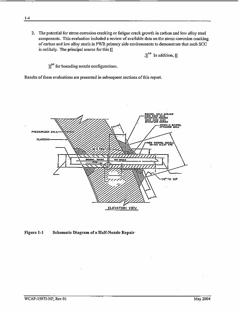


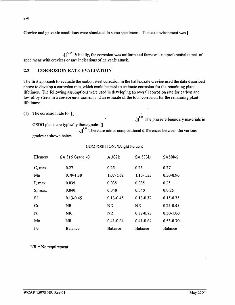


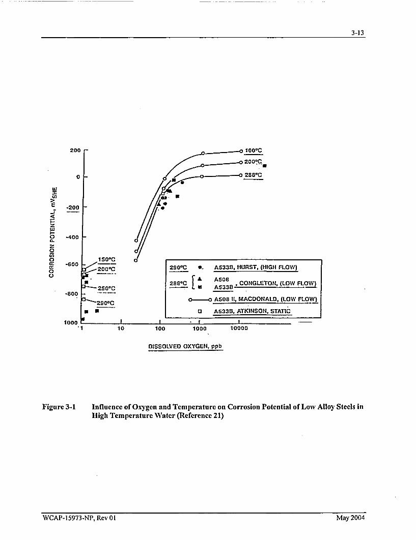
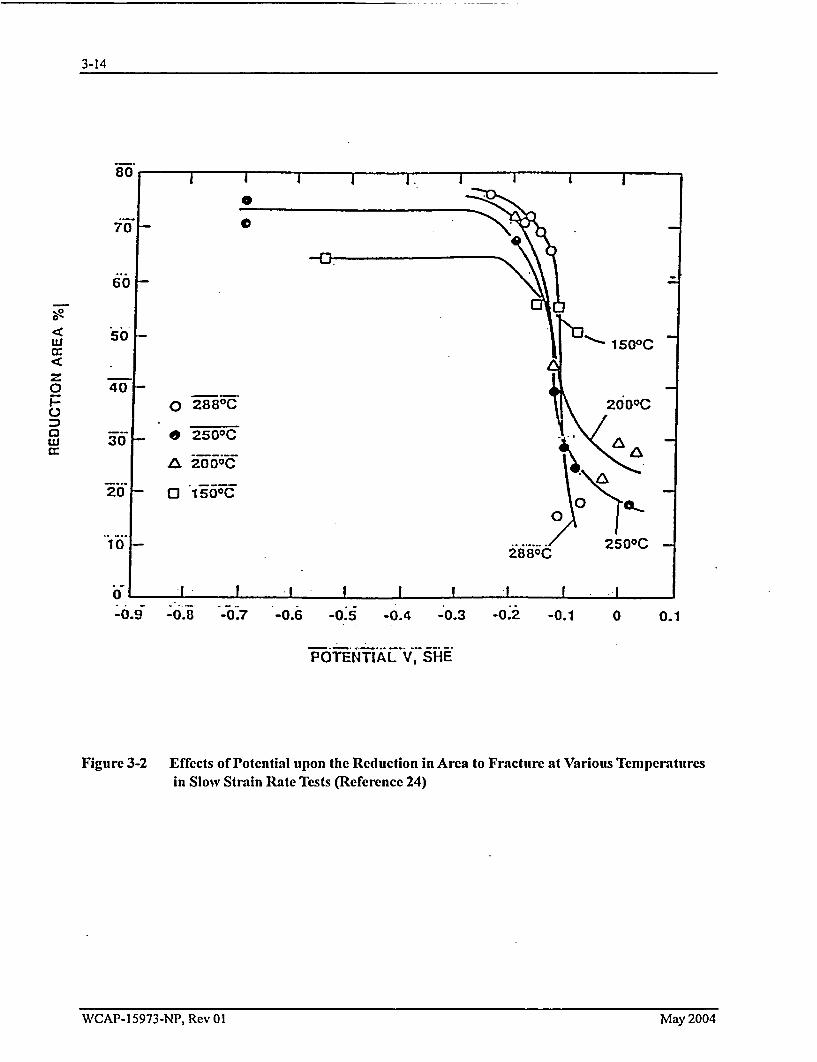


![Attachment 2 Flaw Fracture Mechanics, Corrosion, and Loose ... · 15973-P-A [2] and report CN-CI-02-71 [20]. The NRC has issued a final safety evaluation (SE) [3] that found WCAP-15973-P](https://static.documents.pub/doc/80x56/5f1692622e69473200793c80/attachment-2-flaw-fracture-mechanics-corrosion-and-loose-15973-p-a-2-and.jpg)


