28
WCCU Series Condensing Units Installation, Operation & Maintenance Manual NTC Napps Technology Corporation

WCCU Series
Condensing Units
Installation, Operation &
Maintenance Manual
NTC Napps Technology Corporation

2

3
Table of Contents Model Number Description ........................................................................................................................................ 4
Installation ................................................................................................................................................................... 5
Warnings and Cautions .............................................................................................................................................. 6
Unit Piping ................................................................................................................................................................... 8
Refrigerant Piping ....................................................................................................................................................... 8
Equipment Placement ............................................................................................................................................... 10
Electrical .................................................................................................................................................................... 13
Maintenance .............................................................................................................................................................. 16
General Data .............................................................................................................................................................. 18
Electrical Data ........................................................................................................................................................... 19
Single Circuit WCCU Wiring Diagram .................................................................................................................. 20
Dual Circuit WCCU Wiring Diagram ..................................................................................................................... 21
Field Wiring Diagram ............................................................................................................................................... 22
Water Flow vs. Pressure Drop ................................................................................................................................. 23
Literature Change History ....................................................................................................................................... 25
4
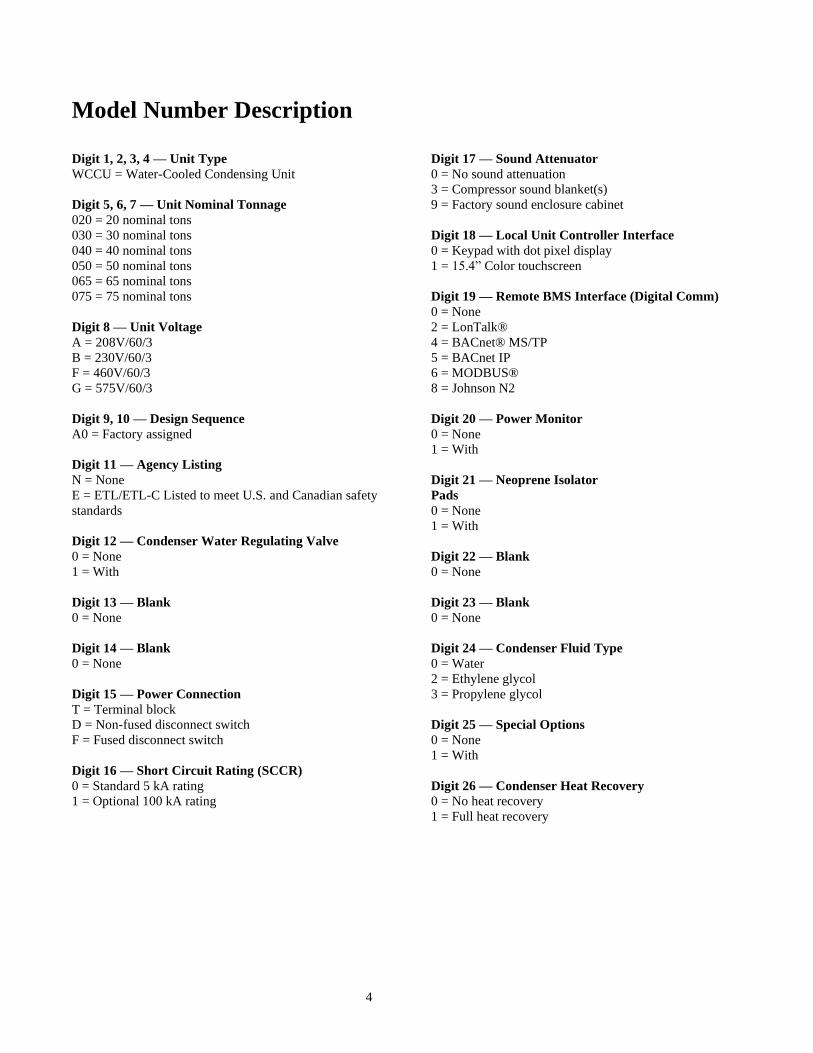
Model Number Description
Digit 1, 2, 3, 4 — Unit Type
WCCU = Water-Cooled Condensing Unit
Digit 5, 6, 7 — Unit Nominal Tonnage
020 = 20 nominal tons
030 = 30 nominal tons
040 = 40 nominal tons
050 = 50 nominal tons
065 = 65 nominal tons
075 = 75 nominal tons
Digit 8 — Unit Voltage
A = 208V/60/3
B = 230V/60/3
F = 460V/60/3
G = 575V/60/3
Digit 9, 10 — Design Sequence
A0 = Factory assigned
Digit 11 — Agency Listing
N = None
E = ETL/ETL-C Listed to meet U.S. and Canadian safety
standards
Digit 12 — Condenser Water Regulating Valve
0 = None
1 = With
Digit 13 — Blank
0 = None
Digit 14 — Blank
0 = None
Digit 15 — Power Connection
T = Terminal block
D = Non-fused disconnect switch
F = Fused disconnect switch
Digit 16 — Short Circuit Rating (SCCR)
0 = Standard 5 kA rating
1 = Optional 100 kA rating
Digit 17 — Sound Attenuator
0 = No sound attenuation
3 = Compressor sound blanket(s)
9 = Factory sound enclosure cabinet
Digit 18 — Local Unit Controller Interface
0 = Keypad with dot pixel display
1 = 15.4” Color touchscreen
Digit 19 — Remote BMS Interface (Digital Comm)
0 = None
2 = LonTalk®
4 = BACnet® MS/TP
5 = BACnet IP
6 = MODBUS®
8 = Johnson N2
Digit 20 — Power Monitor
0 = None
1 = With
Digit 21 — Neoprene Isolator
Pads
0 = None
1 = With
Digit 22 — Blank
0 = None
Digit 23 — Blank
0 = None
Digit 24 — Condenser Fluid Type
0 = Water
2 = Ethylene glycol
3 = Propylene glycol
Digit 25 — Special Options
0 = None
1 = With
Digit 26 — Condenser Heat Recovery
0 = No heat recovery
1 = Full heat recovery
5
Installation
Unit Inspection
When the unit is delivered, verify that it is the
correct unit and that it is properly equipped.
Compare the information, on the unit nameplate,
with the ordering and submittal information
Inspection Checklist
To protect against loss due to damage incurred in
transit, complete the following checklist upon
receipt of the unit.
Inspect the individual pieces of the
shipment before accepting the unit.
Check for obvious damage to the unit or
packing material.
Inspect the unit for concealed damage as
soon as possible after delivery and before
it is stored. Concealed damage must be
reported within 15 days.
If concealed damage is discovered, stop
unpacking the shipment. Do not remove
damaged material from the receiving
location. Take photos of the damage, if
possible. The owner must provide
reasonable evidence that the damage did
not occur after delivery.
Notify the carrier’s terminal of the
damage immediately, by phone and by
mail. Request an immediate, joint
inspection of the damage with the carrier
and the consignee.
Notify the sales representative and
arrange for repair. Do not repair the unit,
however, until damage is inspected by
the carrier’s representative.
Loose Parts Inventory
Check all items against the shipping list. Items,
which are shipped loose, could be placed inside
the unit control panel for shipment. If the
optional neoprene isolators are ordered, they are
secured in place on the shipping skid or inside
the unit control panel.
Unit Description
WCCU condensing units are designed for
installation on a prepared surface, in a suitable
weatherproof enclosure. The WCCU
condensing units consist of two or three scroll
compressors and an integral control panel
mounted on a common base. The WCCU
condensing unit is equipped with a shell-and-
tube type, water cooled condenser.
All units are shipped with a holding charge of dry
nitrogen. Units are dehydrated, leak tested, and
controls are run through a dry functional test
before shipment. The liquid line valve is closed
for shipment to isolate the holding charge in the
unit.
When installing the WCCU, be sure to install a
liquid line solenoid valve, a filter drier, a sight
glass, a thermostatic expansion valve and any
other valves necessary to perform normal service
functions.
The unit wiring diagram and installation and
maintenance manual have been shipped with the
unit and can be found in the unit control panel.
Be sure to read installation and maintenance
manual before installing and operating the unit.
6
Warnings and Cautions
WARNINGS and CAUTIONS appear in
boldface type at appropriate points in this
manual. Your personal safety and reliable
operation of this equipment depend upon strict
observance of these precautions. NTC assumes
no liability for installation or service procedures
performed by unqualified personnel.
Unit Nameplate
The unit nameplate is mounted on the inside of
the control panel door. The nameplate provides
the following information:
Unit model number
Unit serial number
Refrigerant
Maximum operating pressures
Unit electrical requirements
Compressor Nameplate
The nameplate for the hermetic scroll
compressor is mounted on the compressor
housing, near the motor terminal junction box.
Storage
WCCU units are designed for indoor installation
only. Store the unit in a suitable weatherproof
enclosure.
CAUTION: Store these units in a protected
area only. Do not store outdoors with a
protective covering such as a plastic shroud.
This can result in excessive water
condensation that could damage controls and
other components.
Noise Considerations
Locate the unit away from sound-sensitive areas.
If necessary, install the optional isolators under
the unit. Install vibration isolators in all piping
and use flexible electrical conduit. Consult an
acoustical engineer for critical applications
Foundation
A base or foundation is recommended for most
installations. Provide a level surface strong
enough to support the unit. A flexible (isolated)
concrete foundation or footings at each loading
point will reduce transmission of vibration.
Install anchor bolts in the concrete to secure the
unit. If the floor is warped, uneven or in poor
condition, make necessary repairs before
positioning the unit. Once the unit is in place, it
should be level, within ¼” over its entire length
and width.
Clearances
Provide enough space around the unit to allow
the installation and maintenance personnel
unrestricted access to all service points. There
should be adequate clearance for condenser and
compressor servicing. A minimum of three feet
is recommended for compressor service. A
minimum clearance of 3’6” is required to open
the control panel doors. In all cases, local codes
will take precedence over these
recommendations.
Ventilation
Provisions must be made to remove heat
generated by unit operation from the equipment
room. Ventilation must be adequate to maintain
an ambient temperature lower than 125°F.
The condenser relief valve on WCCU units must
be vented in accordance with all local and
national codes.
7
Drainage
Locate the unit near a large capacity drain for
condenser drain-down during shutdown or
repair.
Handling
WCCU units are shipped stretch wrapped and
bolted to a shipping skid.
WARNING! Do not remove the unit from the
shipping skid until it is at the installation
location. Moving these units when not
properly secured to the skid can result in
personal injury, or death, and can seriously
damage the unit.
The skidded unit can be moved by using a fork
truck of suitable capacity.
WARNING! Any on-site lifting equipment
must be capable of handling the weight of the
unit with an adequate safety factor. Use of
under-capacity lifting equipment can result in
personal injury, or death, and can seriously
damage the unit.
When moving the unit, the lifting forks must be
positioned at either end of the unit, under the
shipping skid. Lift the unit and move it to the
desired location.
Once the unit is at the installation location,
remove the stretch wrap. Inspect the unit for
damage and report if damage is found.
The optional unit isolators (if ordered) are
secured to the shipping skid or in the unit control
panel. Other optional items such as the water
regulating valve may be attached to the skid or
shipped separately.
WARNING! To prevent injury or death, and
damage to the unit, the capacity of the lifting
equipment must exceed the unit lifting weight
by an adequate safety factor.
Rigging/Lifting Procedure
If the WCCU is not moved using a forklift, and
the forklift pockets provided as part of the unit's
frame, then the WCCU should be lifted and
moved by using lifting rails as outlined in Step 1
through Step 8.
1. Remove the stretch wrap from the unit,
leaving the unit mounted to the skid.
2. Insert lifting rails through the frame. Secure
the lifting rails to the unit frame by torqueing
1/2” bolts to 70 ft-lbs.
3. Install clevis connectors or equivalent at each
end of the lifting rails.
4. Attach certified lifting chains (cables) to
these points. Each chain (cable) alone must be
strong enough to lift the unit.
5. Attach chains (or cables) to a lifting beam.
Position the chains (cables) so that they do
not contact the unit piping or the unit control
panel. Use a suitable spreader bar to ensure
proper weight distribution.
6. Remove the bolts that secure the unit to the
shipping skid.
7. Raise the unit just off the skid to make sure
that the unit is level when lifted. Adjust chain
(cable) lengths as required for level lifting.
8. Lift the unit off of the skid and place in the
installation location.
Direct Mounting
The unit can be installed directly on a rigid
mounting surface as long as the surface is level
and will support the weight of the unit. A hole is
provided in the unit mounting brackets at each of
the four unit mounting locations. Provide a
means of securely anchoring the unit to the
mounting surface. Level the unit carefully.

8
Unit Piping
General Water Piping Recommendations
Make water piping connections to the condenser.
Isolate and support piping to prevent stress on the
unit. Use flanged ells or spool-pieces to facilitate
service procedures. Construct piping according
to local and national codes. Insulate and flush
the piping before connecting the unit.
Caution: To prevent equipment damage,
bypass the unit if using an acidic flushing
agent.
Use a pipe sealant of Teflon tape on all water
connections. Minimize heat gain and prevent
condensation by insulating all chilled water
piping.
Caution: To prevent damage to water piping,
do not over-tighten connections.
Condenser Water Piping
Condenser piping components and layout vary,
depending on the water source and connection
locations. The optional water regulating valve
maintains condensing pressure and temperature
by throttling water flow leaving the condenser in
response to compressor discharge pressure.
Adjust the regulating valve for proper operation
during unit start-up. Under full load conditions
the water temperature rise should be 10° F,
producing a flow rate in the range of 3 gpm per
ton. Condenser piping must be in accordance
with all local and national codes.
Water Treatment
Using untreated or improperly treated water in
these units may result in inefficient operation and
possible tube damage. Consult a qualified water
treatment specialist to determine if treatment is
needed.
Caution: The use of untreated or improperly
treated water in these units may result in
scaling, erosion, corrosion, algae or slime. The
services of a qualified water treatment
specialist should be engaged to determine if
treatment is needed. NTC warranty
specifically excludes liability for corrosion,
erosion or deterioration of NTC equipment.
NTC assumes no responsibilities for the
results of the use of untreated or improperly
treated water or saline/brackish water
Water Pressure Relief Valves
Install a water pressure relief valve in the
condenser leaving water line. Water vessels with
close-coupled shutoff valves have a high
potential for hydrostatic pressure buildup on a
water temperature increase. Refer to applicable
codes for relief valve installation guidelines.
Refrigerant Piping
General
The refrigerant pipe sizes selected must be within
the velocity and pressure drop limitations
required for proper system operation. It is
essential that refrigerant piping be properly sized
and applied, since these factors have a significant
effect on system performance and reliability.
Note: Piping should be sized and laid out
according to the job plans and specifications.
This should be accomplished when the system
components are selected.
Caution:
Discharge lines, liquid lines, and hot gas
bypass lines that are 1-3/8 inches OD and
smaller, with type-L copper, are suitable for
use with R-410A. These same lines sized at 1-
5/8 inches OD and larger must use type-K or
thicker walls. The use of lower grade tubing
may cause operating problems or injury.
9
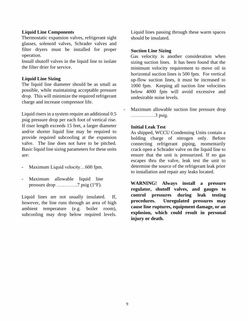
Liquid Line Components
Thermostatic expansion valves, refrigerant sight
glasses, solenoid valves, Schrader valves and
filter dryers must be installed for proper
operation.
Install shutoff valves in the liquid line to isolate
the filter drier for service.
Liquid Line Sizing
The liquid line diameter should be as small as
possible, while maintaining acceptable pressure
drop. This will minimize the required refrigerant
charge and increase compressor life.
Liquid risers in a system require an additional 0.5
psig pressure drop per each foot of vertical rise.
If riser length exceeds 15 feet, a larger diameter
and/or shorter liquid line may be required to
provide required subcooling at the expansion
valve. The line does not have to be pitched.
Basic liquid line sizing parameters for these units
are:
- Maximum Liquid velocity…600 fpm.
- Maximum allowable liquid line
pressure drop ………….7 psig (1°F).
Liquid lines are not usually insulated. If,
however, the line runs through an area of high
ambient temperature (e.g. boiler room),
subcooling may drop below required levels.
Liquid lines passing through these warm spaces
should be insulated.
Suction Line Sizing
Gas velocity is another consideration when
sizing suction lines. It has been found that the
minimum velocity requirement to move oil in
horizontal suction lines is 500 fpm. For vertical
up-flow suction lines, it must be increased to
1000 fpm. Keeping all suction line velocities
below 4000 fpm will avoid excessive and
undesirable noise levels.
- Maximum allowable suction line pressure drop
……………3 psig.
Initial Leak Test
As shipped, WCCU Condensing Units contain a
holding charge of nitrogen only. Before
connecting refrigerant piping, momentarily
crack open a Schrader valve on the liquid line to
ensure that the unit is pressurized. If no gas
escapes thru the valve, leak test the unit to
determine the source of the refrigerant leak prior
to installation and repair any leaks located.
WARNING! Always install a pressure
regulator, shutoff valves, and gauges to
control pressures during leak testing
procedures. Unregulated pressures may
cause line ruptures, equipment damage, or an
explosion, which could result in personal
injury or death.

10
Equipment Placement
Minimize Distance Between Components
For a split air-conditioning system to perform as
reliably and inexpensively as possible, the
refrigerant charge must be kept to a minimum. To
help accomplish this design goal:
• Site the outdoor unit as close to the indoor
unit as possible.
• Route each interconnecting refrigerant line by
the shortest and most direct path so that line
lengths and riser heights are no longer than
absolutely necessary.
• Use only horizontal and vertical piping
configurations.
• Determine whether the total length of each
refrigerant line requires NTC review. Be sure
to account for the difference in elevations of
the indoor and outdoor units when calculating
the total line length.
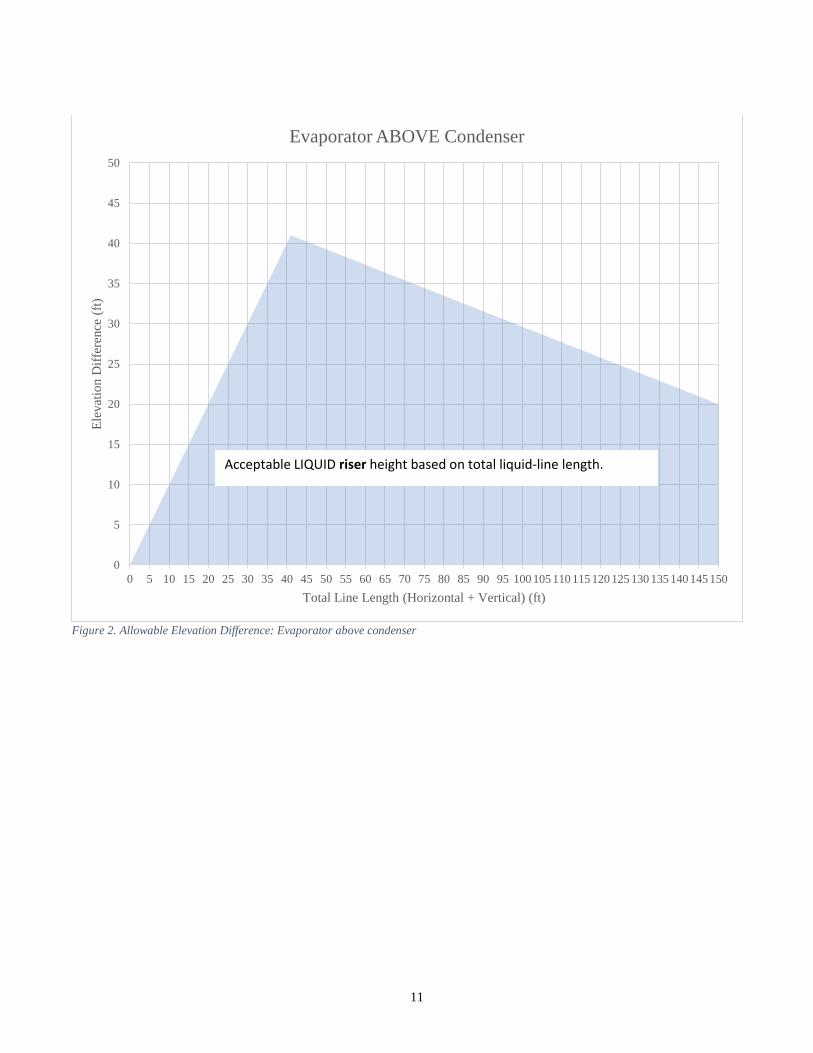
Interconnecting lines of 150 lineal ft (45.7 m) or
less do not require NTC review, but only a
limited amount may be in a riser (see Figure 1.
Allowable elevation difference: Compressor
above evaporator and Figure 2. Allowable
Elevation Difference: Evaporator above
condenser).
Figure 1. Allowable elevation difference: Compressor above evaporator
0
10
20
30
40
50
60
0 5 10 15 20 25 30 35 40 45 50 55 60 65 70 75 80 85 90 95 100 105 110 115 120 125 130 135 140 145 150
Ele
vat
ion D
iffe
rence
(ft
)
Total Line Length (Horizontal + Vertical) (ft)
Compressors ABOVE Evaporator
Acceptable SUCTION riser height based on total suction length
11
Figure 2. Allowable Elevation Difference: Evaporator above condenser
0
5
10
15
20
25
30
35
40
45
50
0 5 10 15 20 25 30 35 40 45 50 55 60 65 70 75 80 85 90 95 100 105 110 115 120 125 130 135 140 145 150
Ele
vat
ion D
iffe
rence
(ft
)
Total Line Length (Horizontal + Vertical) (ft)
Evaporator ABOVE Condenser
Acceptable LIQUID riser height based on total liquid-line length.
12
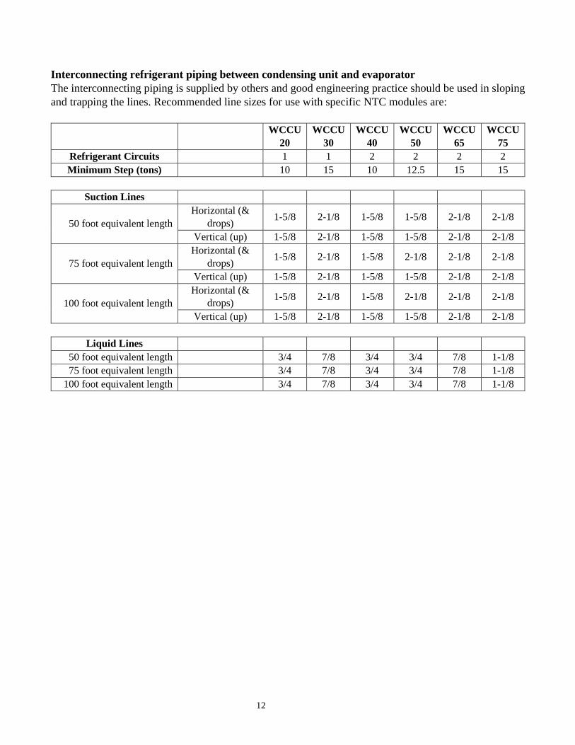
Interconnecting refrigerant piping between condensing unit and evaporator
The interconnecting piping is supplied by others and good engineering practice should be used in sloping
and trapping the lines. Recommended line sizes for use with specific NTC modules are:
WCCU
20
WCCU
30
WCCU
40
WCCU
50
WCCU
65
WCCU
75
Refrigerant Circuits 1 1 2 2 2 2
Minimum Step (tons) 10 15 10 12.5 15 15
Suction Lines
50 foot equivalent length
Horizontal (&
drops) 1-5/8 2-1/8 1-5/8 1-5/8 2-1/8 2-1/8
Vertical (up) 1-5/8 2-1/8 1-5/8 1-5/8 2-1/8 2-1/8
75 foot equivalent length
Horizontal (&
drops) 1-5/8 2-1/8 1-5/8 2-1/8 2-1/8 2-1/8
Vertical (up) 1-5/8 2-1/8 1-5/8 1-5/8 2-1/8 2-1/8
100 foot equivalent length
Horizontal (&
drops) 1-5/8 2-1/8 1-5/8 2-1/8 2-1/8 2-1/8
Vertical (up) 1-5/8 2-1/8 1-5/8 1-5/8 2-1/8 2-1/8
Liquid Lines
50 foot equivalent length 3/4 7/8 3/4 3/4 7/8 1-1/8
75 foot equivalent length 3/4 7/8 3/4 3/4 7/8 1-1/8
100 foot equivalent length 3/4 7/8 3/4 3/4 7/8 1-1/8
13
Electrical
General Recommendations
The wiring procedures, as described in this
portion of the manual, must be accomplished to
obtain proper operation of the basic WCCU unit.
WARNING! To prevent injury or death,
disconnect electrical power source before
completing connections to the unit.
All wiring must comply with National Electrical
Code (NEC) and state and local requirements.
Outside the United States, the national and/or
local electrical requirements of other countries
shall apply. The installer must provide properly
sized system interconnecting and power supply
wiring with appropriate fused disconnect
switches. Type and locations of disconnects
must comply with all applicable codes.
Caution: To prevent corrosion and
overheating at terminal connections, use
copper conductors, sized per NEC and based
on nameplate RLA.
Caution: All wiring must comply with
applicable local and national codes.
Caution: Type and location of fused
disconnect switches must comply with
applicable local and national codes.
Minimum circuit ampacities, recommended fuse
sizes and other unit electrical data are provided
on the unit nameplate.
Unit Power Wiring
The installing contractor must connect
appropriate power wiring to the terminal block or
unit-mounted disconnect in the power section of
the unit control panel. Electrical schematics and
component location drawings are also mounted
on the inside of the control panel door.
The unit power fused disconnect switch should
be located in the general area of the unit, to
comply with NEC or local codes. Some codes
require line-of-sight disconnect locations. The
unit disconnect can be used as an emergency
shutdown device.
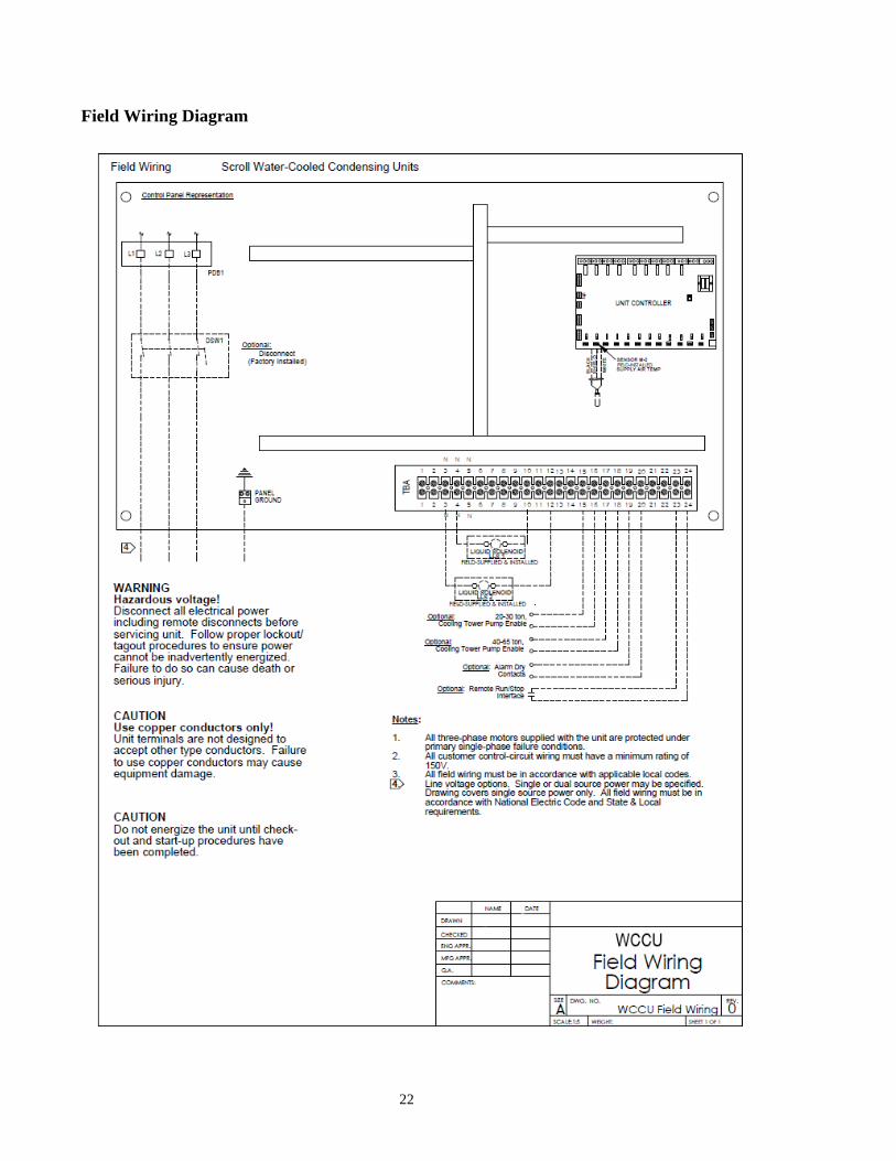
Unit Control Wiring
The installing contractor must connect the unit to
a temperature control device with an
appropriate number of control stages.
A liquid line solenoid valve(s) must be installed.
It is recommended that the evaporator be divided
into the same number of circuits as the
condenser, with a solenoid valve on each circuit.
Terminals are provided for the installation of
devices intended to prevent the unit from
operating under certain conditions. These
devices may include flow switches, building
controllers, pump auxiliary contacts, etc. Refer
to the unit wiring diagram for proper terminal
location. To install more than one device, put the
contacts of all the devices in series.
Terminals are provided for the installation of
additional safety devices. These devices may
include freeze-stats, high-temperature switches,
low temperature switches, etc. Refer to the unit
wiring diagram for proper terminal location.
Contacts installed here should be normally
closed, and open during a fault condition. When
a contact in this position opens, the unit will lock
out and require a reset to continue operating. To
install more than one additional safety device,
put the contacts in series.
Scroll Compressor Electrical Phasing
It is important that proper rotation of the scroll
compressor be established before the machine is
14
started. Proper motor rotation requires
confirmation of the electrical phase sequence of
the power supply. The motor is internally
connected for clockwise rotation with the inlet
power supply phased “ABC” or “L1, L2, L3”.
The order in which the three voltages of a three-
phase system succeed one another is called phase
sequence or phase rotation. When rotation is
clockwise, phase sequence is usually called
“ABC” and when counterclockwise, “CBA”.
This direction may be reversed by interchanging
any two of the line wires. It is this possible
interchange of wiring that makes a phase
sequence indicator necessary, if the operator is to
quickly determine the phase rotation of the
motor.
Setting the Proper Electrical Phase Sequence
Proper compressor motor electrical phasing can
be quickly determined and, if necessary,
corrected before starting the unit. Use a quality
Phase Sequence indicator and follow this
procedure.
1. Verify that all operating controls for the unit
are in the “Off” position.
2. Deenergize the electrical disconnect or
circuit protection switch that provides line
power to the power distribution block in the
unit control panel
3. Connect the phase sequence indicator leads
to the power distribution block as follows:
Phase Seq. Lead Terminal ID
Black (Phase A)
Red (Phase B)
L1
L2
Yellow (Phase C) L3
4. Turn power on by closing the unit supply
power fused disconnect switch.
5. Read the phase sequence displayed on the
indicator. The “ABC” LED on the face of the
phase indicator will glow if phase sequence
is ABC
WARNING! To prevent injury or death due
to electrocution, take extreme care when
performing service procedures with electrical
power energized.
6. If the “CBA” indicator glows instead,
deenergize the unit main power disconnect
and switch two line leads on the power
distribution block in the unit control panel.
Close the main power disconnect and
recheck phasing.
7. Deenergize the unit disconnect and remove
the phase indicator.
Unit Voltage
Electrical power to the unit must meet stringent
requirements for the unit to operate properly.
Total voltage supply and voltage imbalance
between phases should be within the tolerances
discussed as follows.
Voltage Supply
Measure each leg of supply voltage at the line
voltage disconnect switches. Readings must fall
within the range of 187-253 volts for units with a
nameplate voltage of 208/230 volt and 414-506
volts for units with a nameplate voltage of 460
volts. If voltage on any leg does not fall within
tolerance, notify the power company and request
correction of this situation before operating the
unit. Inadequate voltage to the unit will shorten
the life of relay contacts and compressor motors.
15
Voltage Imbalance
Excessive voltage imbalance between phases in
a three-phase system will cause motors to
overheat and eventually fail. Maximum
allowable imbalance is 2 percent. Voltage
imbalance is defined as 100 times the maximum
deviation of the three voltages (three phases)
subtracted from the average (without regard to
sign), divided by the average voltage.
Equipment Grounds
Provide proper grounding at the connection point
provided in the unit control panel.
Installation Checklist
As the unit is installed, complete this checklist to
verify that all recommended procedures are
accomplished before the unit is started. This
checklist does not replace the detailed
instructions given in previous sections of this
manual. Read the entire installation section
carefully to become familiar with the procedures
before installing the unit.
Unit Location
Inspect installation location for adequate
ventilation.
Provide drain facilities for condenser.
Remove and discard all shipping material
(skid, etc.).
Inspect to ensure that all service access
clearances are adequate.
Install optional neoprene isolators (if
required).
Secure the unit to the mounting surface.
Level the unit.
Condenser Connections
Make condenser water connections.
Install a water regulating valve in the water
outlet line, if required.
Install shutoff valves, temperature sensors,
plugged clean-out tees, and pressure gauges
in the water inlet and outlet lines.
Install a water strainer and pressure reducing
valve on the water inlet piping.
Install drain piping with shutoff valves.
Install a manual or automatic bypass valve in
the cooling tower water supply (if used).
Install refrigerant discharge piping for the
condenser relief valve.
Flush and clean all condensing water piping.
Refrigerant Piping
Perform the initial leak test.
Connect a properly sized and constructed
liquid line (with charging valve, solenoid
valve, filter drier, sight glass, and expansion
valve) to the liquid line connection on the
condenser.
Connect a properly sized and constructed
suction line from the evaporator to the
suction line connection at the compressor.
Insulate the suction line. Also insulate the
hot gas bypass line (if used).
Insulate the lengths of discharge or liquid line
that are exposed to extremes in temperature.
Leak test the unit and all piping connections.
Power Supply Wiring
Connect proper power supply wiring to the
power distribution block (or unit mounted
disconnect) in the unit control panel.
Connect proper power supply wiring, with
fused disconnects, to the condenser water
pump starter, to the cooling tower fan starter
(if used).
Connect proper power supply wiring to the
evaporator fan coil.
16
System Interconnection Wiring
Connect proper wiring to interlock the
condenser water pump and the cooling tower
operation with unit start-up.
Provide proper wiring to interlock the unit
start-up with airflow switch operation.
Connect proper wiring to interlock the liquid
line solenoid valve operation with unit call
for cooling.
Maintenance
Compressor Oil
Oil Level. While the compressor is running, the
oil level may be below the sight glass but still
visible through the sight glass. The oil level
should never be above the sight glass.
Oil Appearance. If the oil is dark and smells
burnt, it was overheated because of compressor
operation at extremely high condensing
temperatures, a compressor mechanical failure,
or occurrence of a motor burnout. If the oil is
black and contains metal flakes, a mechanical
failure has occurred. This symptom is often
accompanied by a high amperage draw at the
compressor motor.
Note: If a motor burnout is suspected, use an
acid test kit to check the condition of the oil. If a
burnout has occurred, test results will indicate an
acid level exceeding 0.05 mg KOH/g.
Note: The use of commercially available oil
additives is not recommended. Liability for any
detrimental effects that the use of non-approved
products may have on equipment performance or
longevity must be assumed by the equipment
owner, equipment servicer, or the oil additive
manufacturer.
Compressor Motor Winding Thermostat
Each motor winding thermostat is a pilot-duty
control, designed to stop compressor operation if
the motor windings become hot due to rapid
cycling, loss of charge, abnormally low suction
temperatures, or the compressor running
backwards.
Compressor Electrical Phasing
Proper phasing of the electrical power is critical
for proper operation and reliability of the scroll
compressor. If the compressor electrical phasing
is incorrect, the motor will draw low current, the
suction and discharge pressures will change very
little, and a rumble or rattle may be heard.
Scroll Compressor Functional Test
Since the scroll compressor does not use
discharge or suction valves, it is not necessary
to perform a pump-down capability test, i.e. a
test where the liquid line valve is closed and the
compressor is pumped in a vacuum to confirm it
will pump-down and hold.
Caution: Do not pump the scroll compressor
into a vacuum. Scroll compressors can pull
internal low vacuums when the suction side is
closed or restricted. This result in compressor
damage or failure. It may also trip the circuit
breakers, blow fuses, or trip the discharge
thermostat.
The proper procedure for checking scroll
compressor operation is outlined below:
1. Verify that the compressor is receiving
supply power of the proper voltage.
2. With the compressor running, measure the
suction and discharge pressures to determine
whether or not they fall within the normal
operating ranges for the unit.
3. If the operating pressures are not correct, see
“Scroll Compressor Electrical Phasing”.
17
Compressor Operational Noises
Because the scroll compressor is designed to
accommodate liquids (both oil and refrigerant),
for short periods, without causing compressor
damage, there are some characteristic sounds that
may be heard. These sounds, which are
described below, are normal and do not indicate
that the compressor is defective.
At low condensing temperature start-up: When
the compressor starts up under low condensing
temperatures, the initial flow rate of the
compressor is low, due to the low condensing
pressure. This causes a low differential across
the thermal expansion valve that limits its
capacity. Under these conditions, it is not
unusual to hear the compressor rattle until the
suction pressure climbs and the flow rate
increases. These sounds are normal and do not
affect the operation or reliability of the
compressor.
Low Suctions
Low suctions can be caused by a plugged screen
on the compressor suction inlet. If the screen is
plugged, the pressure in the oil sump, as
measured at the oil charging valve, will be lower
than the suction pressure measured at the
evaporator.
Also, low suction pressures may be caused by
low evaporator load. Other symptoms that may
accompany low suctions include a rattling sound
emitted from the compressor or an open motor
winding thermostat or discharge thermostat.
Excess Amp Draw
Normally this condition occurs either because the
compressor is operating at an abnormally high
condensing temperature or because of low
voltage at the compressor motor. Motor amp
draw may also be excessive if the compressor has
internal mechanical damage. In this situation,
vibration and discolored oil can also be observed.
Excessive Vibration
If the compressor vibrates and does not pump,
check the compressor phasing as described in
“Scroll Compressor Electrical Phasing” and
check the oil level and the oil’s appearance.
Periodic Maintenance
Perform all of the indicated maintenance
procedures at the intervals scheduled. This will
prolong the life of the unit and reduce the
possibility of costly equipment failure.
Monthly
Check compressor oil level.
Check unit refrigerant charge by measuring
sub-cooling or visually checking the sight
glass for the presence of bubbles.
Check refrigerant superheat at the
compressor suction line. Superheat should
be in the range of 10°-20°F.
Check compressor phasing (See “Scroll
Compressor Electrical Phasing”).
Annually
* With the unit disconnect switch deenergized,
inspect the panel wiring. All electrical
connections should be secure. Inspect the
compressor contactors. If the contacts appear
severely burned or pitted, replace the
contactor. Do not clean the contacts.
* Remove any accumulation of dust and dirt
from the unit.
* Check condenser water flow rate.
* With unit operating, check refrigerant
discharge and suction pressures.
18
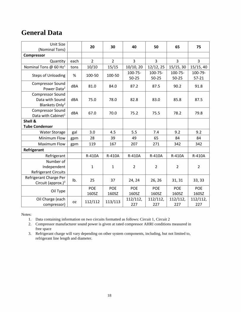
General Data
Unit Size (Nominal Tons)
20 30 40 50 65 75
Compressor
Quantity each 2 2 3 3 3 3
Nominal Tons @ 60 Hz1 tons 10/10 15/15 10/10, 20 12/12, 25 15/15, 30 15/15, 40
Steps of Unloading % 100-50 100-50 100-75-50-25
100-75-50-25
100-75-50-25
100-79-57-21
Compressor Sound Power Data2
dBA 81.0 84.0 87.2 87.5 90.2 91.8
Compressor Sound Data with Sound
Blankets Only2 dBA 75.0 78.0 82.8 83.0 85.8 87.5
Compressor Sound Data with Cabinet2
dBA 67.0 70.0 75.2 75.5 78.2 79.8
Shell & Tube Condenser
Water Storage gal 3.0 4.5 5.5 7.4 9.2 9.2
Minimum Flow gpm 28 39 49 65 84 84
Maximum Flow gpm 119 167 207 271 342 342
Refrigerant
Refrigerant R-410A R-410A R-410A R-410A R-410A R-410A
Number of Independent
Refrigerant Circuits
1 1 2 2 2 2
Refrigerant Charge Per Circuit (approx.)3
lb. 25 37 24, 24 26, 26 31, 31 33, 33
Oil Type POE 160SZ
POE 160SZ
POE 160SZ
POE 160SZ
POE 160SZ
POE 160SZ
Oil Charge (each compressor)
oz 112/112 113/113 112/112,
227 112/112,
227 112/112,
227 112/112,
227
Notes:
1. Data containing information on two circuits formatted as follows: Circuit 1, Circuit 2
2. Compressor manufacturer sound power is given at rated compressor AHRI conditions measured in
free space
3. Refrigerant charge will vary depending on other system components, including, but not limited to,
refrigerant line length and diameter.
19
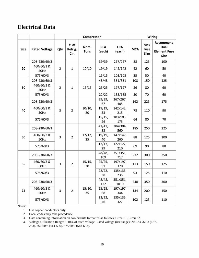
Electrical Data Compressor Wiring
Size Rated Voltage Qty # of
Refrig. Cir.
Nom. Tons
RLA (each)
LRA (each)
MCA Max Fuse Size
Recommend Dual
Element Fuse Size
20
208-230/60/3
2 1 10/10
39/39 267/267 88 125 100
460/60/3 & 50Hz
19/19 142/142 42 60 50
575/60/3 15/15 103/103 35 50 40
30
208-230/60/3
2 1 15/15
48/48 351/351 108 150 125
460/60/3 & 50Hz
25/25 197/197 56 80 60
575/60/3 22/22 135/135 50 70 60
40
208-230/60/3
3 2 10/10,
20
39/39, 67
267/267, 485
162 225 175
460/60/3 & 50Hz
19/19, 33
142/142, 215
78 110 90
575/60/3 15/15,
26 103/103,
175 64 80 70
50
208-230/60/3
3 2 12/12,
25
41/41, 82
304/304, 560
185 250 225
460/60/3 & 50Hz
19/19, 40
147/147, 260
88 125 100
575/60/3 17/17,
29 122/122,
210 69 90 80
65
208-230/60/3
3 2 15/15,
30
48/48, 109
351/351, 717
232 300 250
460/60/3 & 50Hz
25/25, 51
197/197, 320
113 150 125
575/60/3 22/22,
38 135/135,
235 93 125 110
75
208-230/60/3
3 2 15/20,
35
48/48, 122
351/351, 1010
248 350 300
460/60/3 & 50Hz
25/25, 68
197/197, 344
134 200 150
575/60/3 22/22,
46 135/135,
327 102 125 110
Notes:
1. Use copper conductors only.
2. Local codes may take precedence.
3. Data containing information on two circuits formatted as follows: Circuit 1, Circuit 2
4. Voltage Utilization Range: ± 10% of rated voltage. Rated voltage (use range): 208-230/60/3 (187-
253), 460/60/3 (414-506), 575/60/3 (518-632).
20
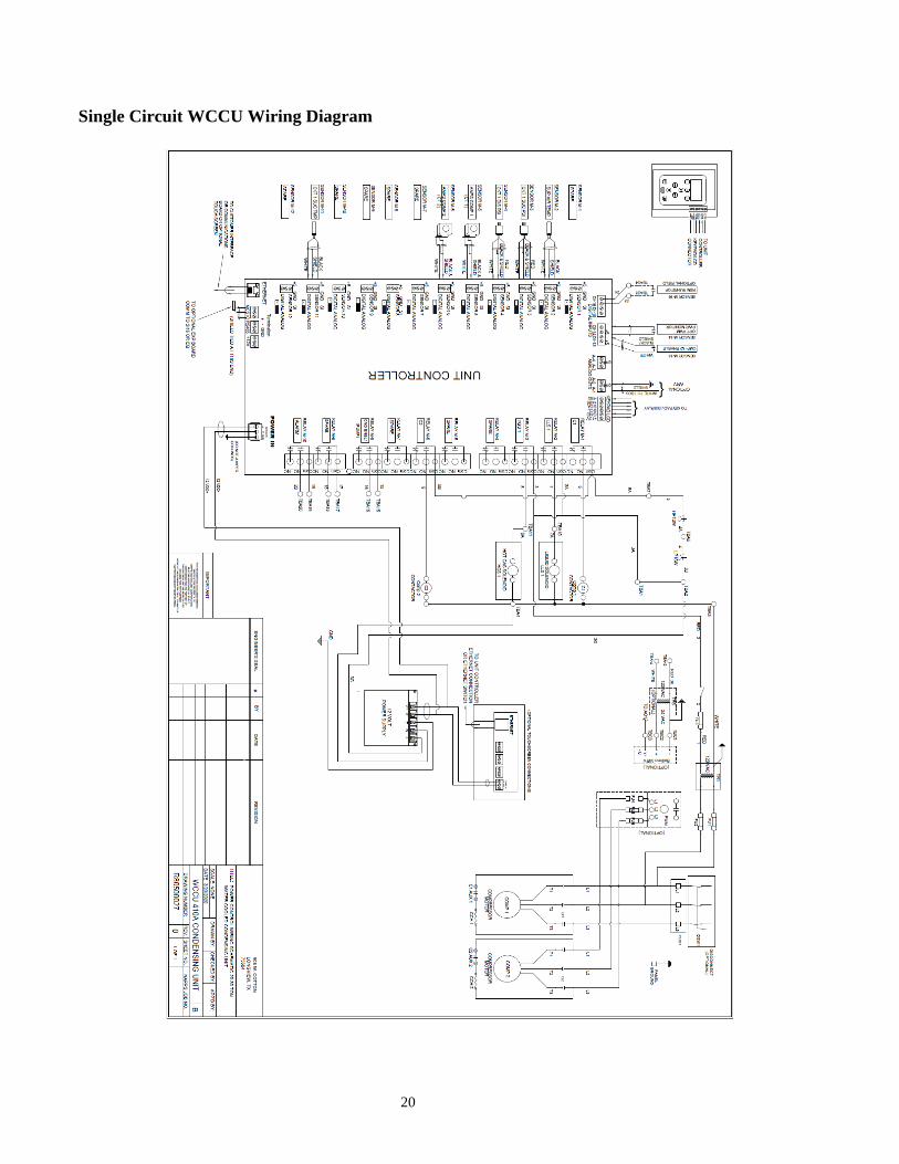
Single Circuit WCCU Wiring Diagram
21
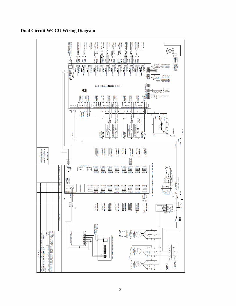
Dual Circuit WCCU Wiring Diagram
22
Field Wiring Diagram
23
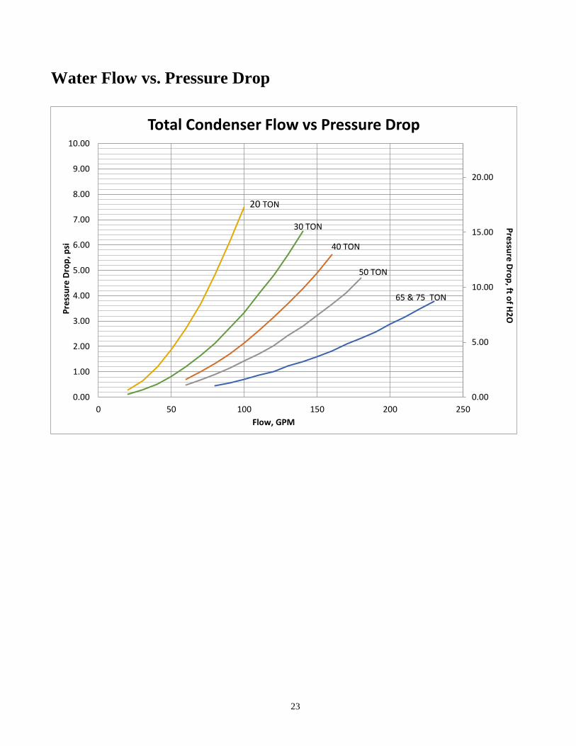
Water Flow vs. Pressure Drop
Pre
ssure
Dro
p, ft o
f H2
O
0.00
5.00
10.00
15.00
20.00
0.00
1.00
2.00
3.00
4.00
5.00
6.00
7.00
8.00
9.00
10.00
0 50 100 150 200 250
Pre
ssu
re D
rop
, psi
Flow, GPM
Total Condenser Flow vs Pressure Drop
20 TON
30 TON
50 TON
40 TON
65 & 75 TON

24
I. LIMITED PRODUCT WARRANTY & SERVICE POLICY
Napps Technology Corporation (NTC) warrants for a period of twelve (12) months from date of original shipment that
all products, manufactured by NTC, with the exception of packaged refrigeration products, are free from defects of
material and workmanship when used within the service, range, and purpose for which they were manufactured.
Packaged refrigeration products shall be so warranted for a period of twelve (12) months from date of start-up or
eighteen (18) months from date of original shipment, whichever may first occur. Service Parts shall be so warranted
for a period of ninety (90) days from date of installation, or twelve (12) months from date of original shipment,
whichever may first occur.
In case material is rejected on inspection by the buyer as defective, NTC shall be notified in writing within ten (10) days
from receipt of said material. NTC will then have the option of re-inspection at the buyer's plant or its own plant before
allowing or rejecting the buyer's claim. Expenses incurred in connection with claims for which NTC is not liable may
be charged back to the buyer. No claim for correction will be allowed for work done in the field except with the written
consent of NTC. Defects that do not impair service shall not be cause for rejection. NTC assumes no liability in any
event for consequential damages. No claim will be allowed for material damaged by the buyer or in transit. Defective
equipment or parts shall be returned to NTC freight prepaid.
NTC will, at its option, repair, replace or refund the purchase price of products found by NTC to be defective in material
or workmanship provided that written notice of such defect requesting instruction for repair, replacement or refund is
received by NTC within ten (10) days of determination of said defect, but not more than one (1) year after the date of
shipment, and provided that any instructions given thereafter by NTC are followed.
Any products covered by this order found to NTC satisfaction to be defective upon examination at NTC factory will, at
NTC option, be repaired or replaced and returned to Buyer via lowest cost common carrier, or NTC may, at its option,
grant Buyer a credit for the purchase price of the defective article.
This warranty does not cover and does not apply to:
(1) Fuses, refrigerant, fluids, oil;
(2) Products relocated after initial installation;
(3) Any portion or component of the system that is not supplied by NTC, regardless of the cause of the failure of
such portion or component;
(4) Products on which the unit’s identification tags or labels have been removed or defaced;
(5) Products on which payment to NTC is or has been in default;
(6) Products which have defects or damage which result from improper installation, wiring, electrical imbalance
characteristics or maintenance (including, without limitation, defects or damages caused by voltage surges,
inadequate voltage conditions, phase imbalance, any form of electrical disturbances, inadequate or improper
electrical circuit installation or protection, failure to perform common maintenance, etc.); or are caused by
accident, misuse or abuse, fire, the elements, shock, vibration, flood, alteration, misapplication of the product
or to any other service, range or environment of greater severity than that for which the products were
designed;
(7) Products which have defects or damage which result from a contaminated or corrosive air or liquid supply,
operation at abnormal temperatures, or unauthorized opening of refrigerant circuit;
(8) Products subjected to corrosion or abrasion or chemicals;
(9) Mold, fungus or bacteria damage;
(10) Products manufactured or supplied by others;
(11) Products which have been subjected to misuse, negligence, vandalism or accidents;
(12) Products which have been operated in a manner contrary to NTC printed instructions;
(13) Products which have defects, damage or insufficient performance as a result of insufficient or incorrect system
design or the improper application of NTC products;
(14) Products which have defects or damages due to freezing of the water supply, an inadequate or interrupted
water supply, corrosives or abrasives in the water supply, or improper or inadequate filtration or treatment of
the water or air supply.
(15) Water-to-refrigerant heat exchanger for any damage resulting from freezing, fouling, corrosion or clogging.
25
NTC is not responsible for:
(1) The costs of any fluids, oils refrigerant or other system components, or the associated labor to repair or replace the
same, which is incurred as a result of a defective part covered by NTC Limited Product Warranty;
(2) The costs of labor, refrigerant, materials or service incurred in removal of the defective part, or in obtaining and
replacing the new or repaired part; or,
(3) Transportation costs of the defective part from the installation site to NTC or the return of any part not covered by
NTC Limited Product Warranty.
THE WARRANTY PROVIDED ABOVE IS THE ONLY WARRANTY MADE BY NTC WITH RESPECT TO ITS PRODUCTS OR
ANY PARTS THEREFORE AND IS MADE EXPRESSLY IN LIEU OF ANY OTHER WARRANTIES, BY COURSE OF DEALING,
USAGES OF TRADE OR OTHERWISE, EXPRESSED OR IMPLIED, INCLUDING BUT NOT LIMITED TO ANY IMPLIED
WARRANTIES OF FITNESS FOR ANY PARTICULAR PURPOSE OR OF MERCHANTABILITY UNDER THE UNIFORM
COMMERCIAL CODE. IT IS AGREED THAT THIS WARRANTY IS IN LIEU OF AND BUYER HEREBY WAIVES ALL OTHER
WARRANTIES, GUARANTEES OR LIABILITIES ARISING BY LAW OR OTHERWISE. NTC SHALL NOT INCUR ANY OTHER,
OBLIGATIONS OR LIABILITIES OR BE LIABLE TO BUYER OR ANY CUSTOMER OF BUYER FOR ANY ANTICIPATED OR
LOST PROFITS, INCIDENTAL OR CONSEQUENTIAL DAMAGES, OR ANY OTHER LOSSES OR EXPENSES INCURRED BY
REASON OF THE PURCHASE, INSTALLATION, REPAIR, USE OR MISUSE BY BUYER OR THIRD PARTIES OF ITS
PRODUCTS (INCLUDING ANY PARTS REPAIRED OR REPLACED); AND NTC DOES NOT AUTHORIZE ANY PERSON TO
ASSUME FOR NTC ANY OTHER LIABILITY IN CONNECTION WITH THE PRODUCTS OR PARTS THEREFORE. NTC SHALL
NOT BE RESPONSIBLE FOR THE LOSS OR REPLACEMENT OF OR THE ADDITION OF COMPRESSOR OIL, OR
REFRIGERANT. THIS WARRANTY CANNOT BE EXTENDED, ALTERED OR VARIED EXCEPT BY A WRITTEN
INSTRUMENT SIGNED BY NTC AND BUYER.
II. LIMITATION OF LIABILITY
NTC shall not be liable, in contract or in tort, for any special, indirect, incidental or consequential damages, such as,
but not limited to, loss of profits, or injury or damage caused to property, products, or persons by reason of the
installation, modification, use, repair, maintenance or mechanical failure of any NTC product.
Literature Change History 7/9/2019 – New Literature
3/18/2020 – Added General Data and Pressure Drop Curves
3/24/2020 – Updated wiring diagrams

26

27
28
NTC Napps Technology Corporation
905 W. Cotton Street
Longview, TX 75604
Phone: 903-758-2900
www.nappstech.com
Installation Manual - WCCU Series
Revision 200327
It is the intent of NTC to provide accurate up-to-date specification data. However, in the interest of
ongoing product improvement, Napps Technology Corporation reserves the right to change specifications
and/or design of any product without notice, obligation, or liability.


