31
Troubleshooting Catalyst Losses in the FCC Unit Rebecca Kuo, Technical Service Engineer RefComm Galveston 2016 1 We create chemistry that makes individual refiners love fueling the world.
Troubleshooting Catalyst Losses in the FCC UnitRebecca Kuo, Technical Service EngineerRefComm Galveston 2016
1
We create chemistry
that makes individual refiners love fueling the world.
Overview
■ Introduction
■ Cyclone Fundamentals
■ Catalyst Attrition
■ Monitoring and Troubleshooting Catalyst Losses
■ Handling High Catalyst Losses
■ Questions
2
Introduction
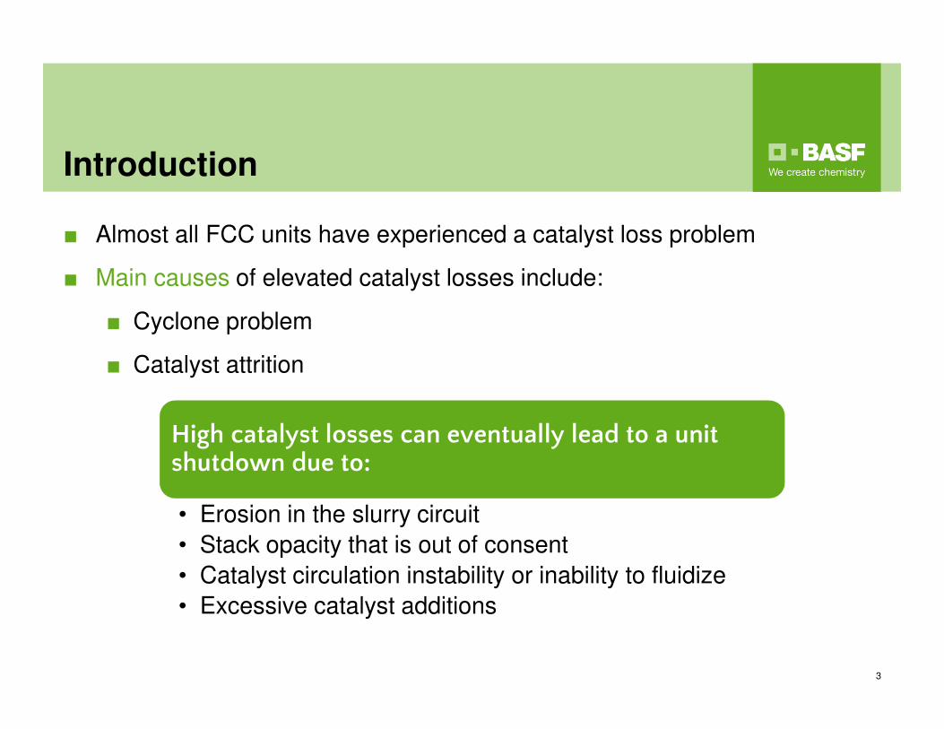
■ Almost all FCC units have experienced a catalyst loss problem
■ Main causes of elevated catalyst losses include:
■ Cyclone problem
■ Catalyst attrition
3
High catalyst losses can eventually lead to a unit shutdown due to:
• Erosion in the slurry circuit
• Stack opacity that is out of consent
• Catalyst circulation instability or inability to fluidize
• Excessive catalyst additions
Cyclone Fundamentals
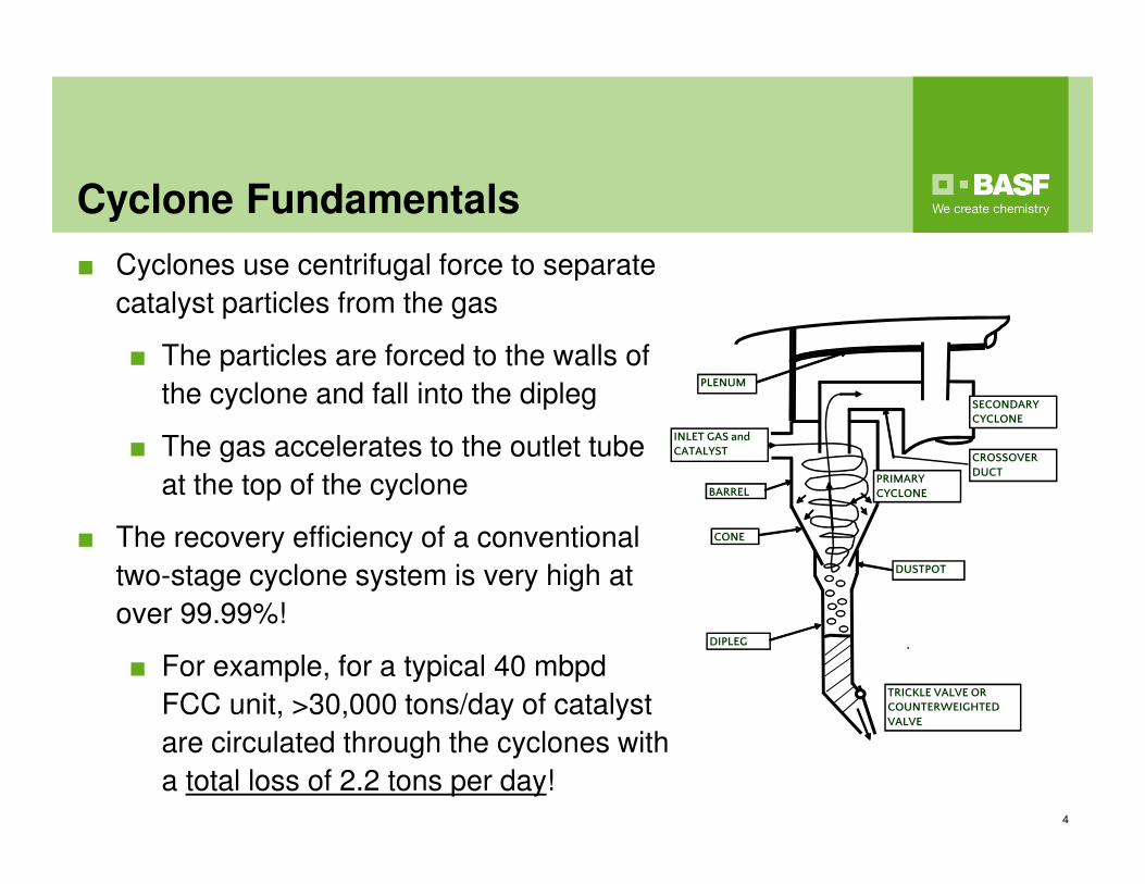
■ Cyclones use centrifugal force to separate
catalyst particles from the gas
■ The particles are forced to the walls of
the cyclone and fall into the dipleg
■ The gas accelerates to the outlet tube
at the top of the cyclone
■ The recovery efficiency of a conventional
two-stage cyclone system is very high at
over 99.99%!
■ For example, for a typical 40 mbpd
FCC unit, >30,000 tons/day of catalyst
are circulated through the cyclones with
a total loss of 2.2 tons per day!4
TRICKLE VALVE OR COUNTERWEIGHTED VALVE
CONE
DIPLEG
DUSTPOT
BARREL
INLET GAS and CATALYST
PLENUM
CROSSOVER DUCT
PRIMARY CYCLONE
SECONDARY CYCLONE
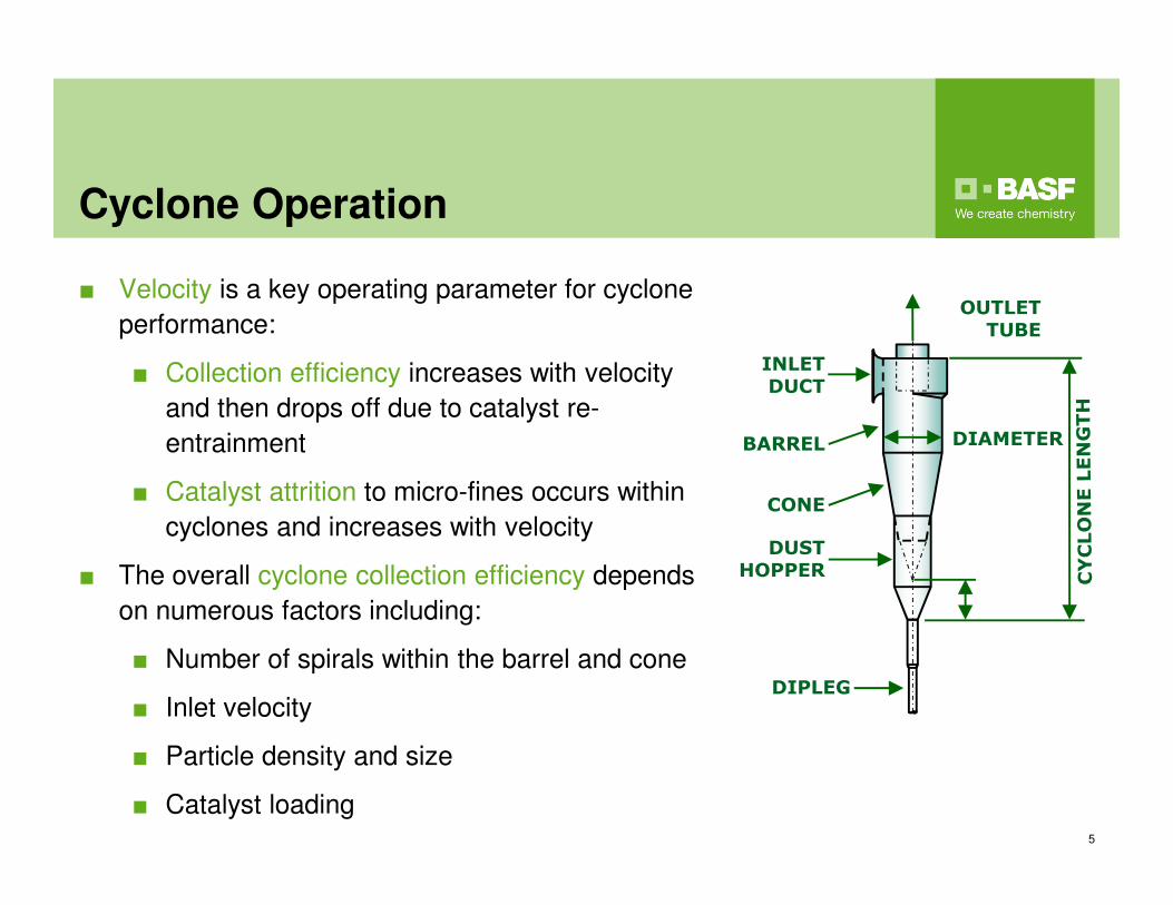
Cyclone Operation
■ Velocity is a key operating parameter for cyclone
performance:
■ Collection efficiency increases with velocity
and then drops off due to catalyst re-
entrainment
■ Catalyst attrition to micro-fines occurs within
cyclones and increases with velocity
■ The overall cyclone collection efficiency depends
on numerous factors including:
■ Number of spirals within the barrel and cone
■ Inlet velocity
■ Particle density and size
■ Catalyst loading5
INLET
DUCT
OUTLET
TUBE
DIAMETERBARREL
CONE
DUST
HOPPER
DIPLEG
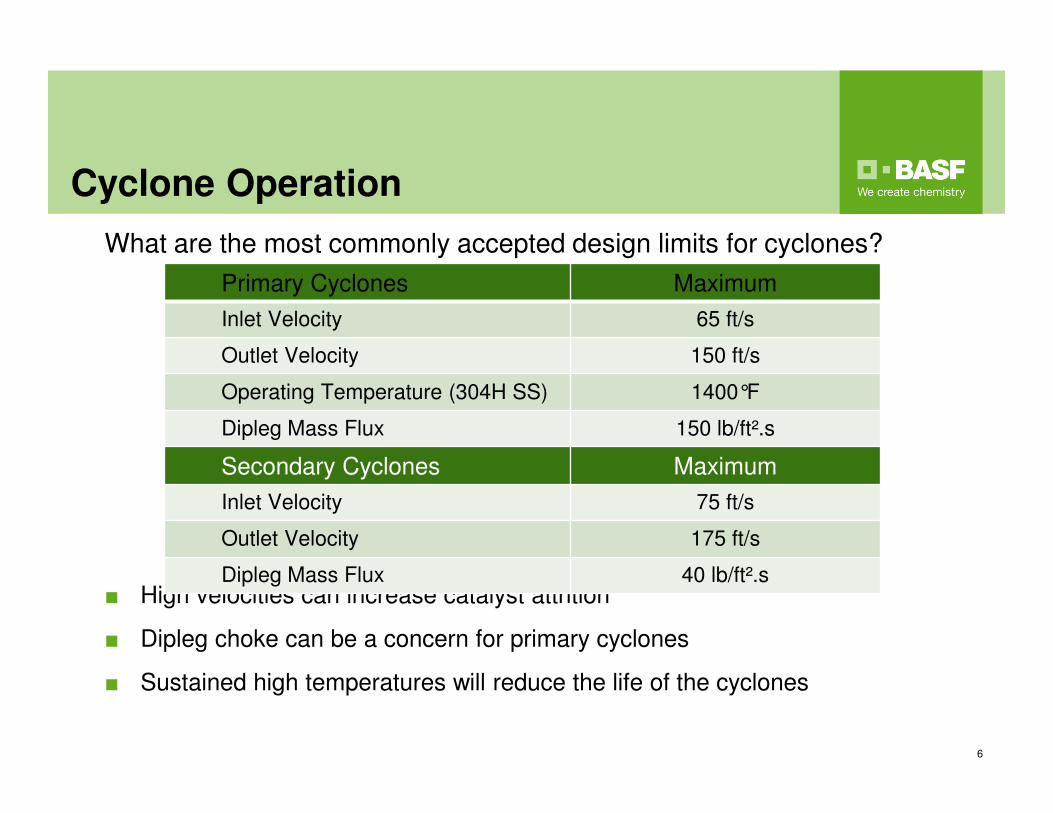
Cyclone Operation
What are the most commonly accepted design limits for cyclones?
■ High velocities can increase catalyst attrition
■ Dipleg choke can be a concern for primary cyclones
■ Sustained high temperatures will reduce the life of the cyclones
6
Primary Cyclones Maximum
Inlet Velocity 65 ft/s
Outlet Velocity 150 ft/s
Operating Temperature (304H SS) 1400°F
Dipleg Mass Flux 150 lb/ft².s
Secondary Cyclones Maximum
Inlet Velocity 75 ft/s
Outlet Velocity 175 ft/s
Dipleg Mass Flux 40 lb/ft².s
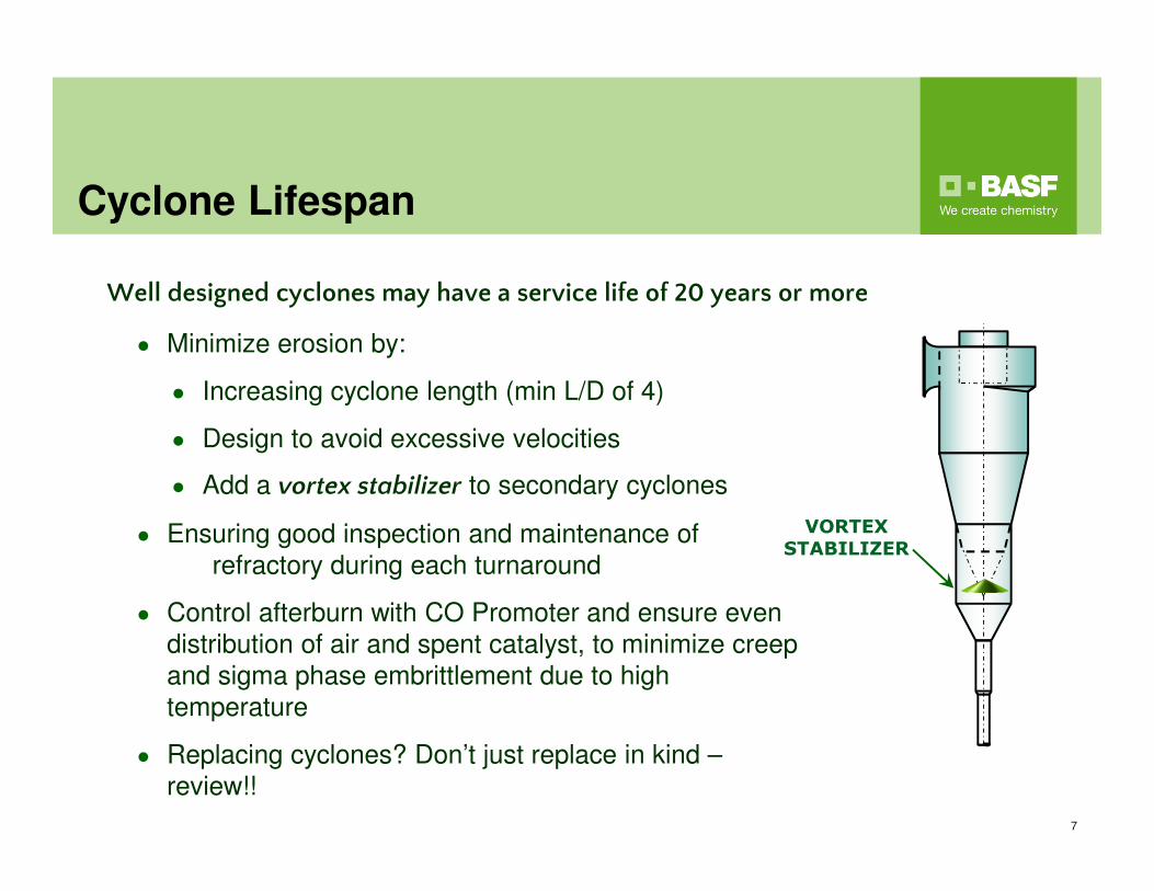
Cyclone Lifespan
7
● Minimize erosion by:
● Increasing cyclone length (min L/D of 4)
● Design to avoid excessive velocities
● Add a vortex stabilizer to secondary cyclones
● Ensuring good inspection and maintenance of
refractory during each turnaround
● Control afterburn with CO Promoter and ensure even
distribution of air and spent catalyst, to minimize creep
and sigma phase embrittlement due to high
temperature
● Replacing cyclones? Don’t just replace in kind –
review!!
Well designed cyclones may have a service life of 20 years or more
VORTEX
STABILIZER
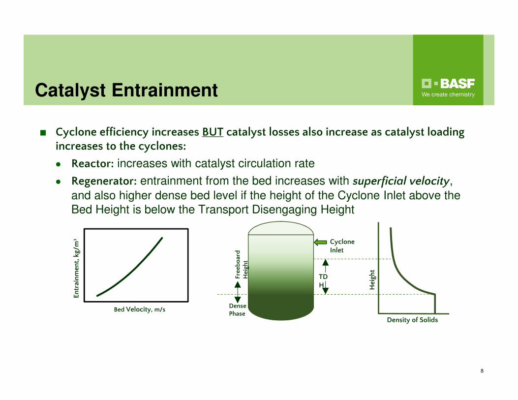
Catalyst Entrainment
8
■ Cyclone efficiency increases BUT catalyst losses also increase as catalyst loading increases to the cyclones:
● Reactor: increases with catalyst circulation rate
● Regenerator: entrainment from the bed increases with superficial velocity,
and also higher dense bed level if the height of the Cyclone Inlet above the
Bed Height is below the Transport Disengaging Height
Bed Velocity, m/s
Entrainment, kg/m³
Density of Solids
Height
Cyclone Inlet
Dense Phase
Freeboard
Height
TDH
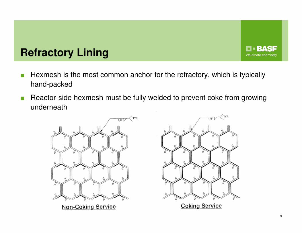
Refractory Lining
■ Hexmesh is the most common anchor for the refractory, which is typically
hand-packed
■ Reactor-side hexmesh must be fully welded to prevent coke from growing
underneath
9
Common Cyclone Problems: Dipleg
Malfunction
10
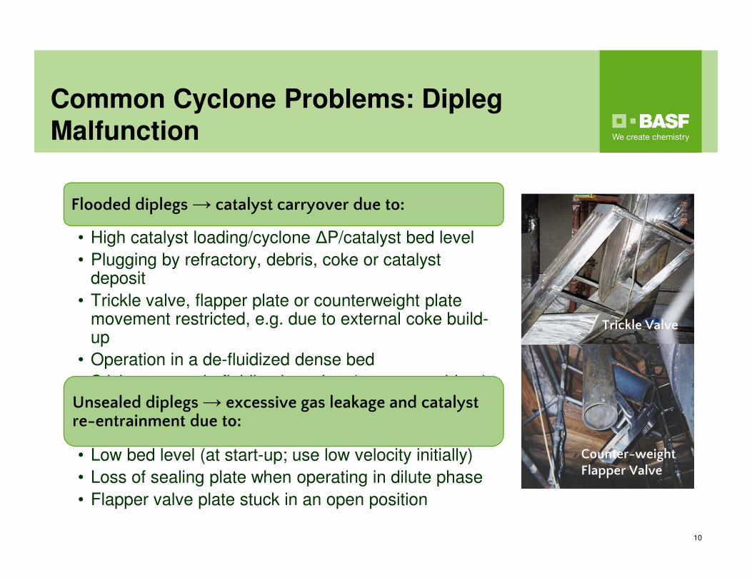
Flooded diplegs → catalyst carryover due to:
• High catalyst loading/cyclone ΔP/catalyst bed level
• Plugging by refractory, debris, coke or catalyst deposit
• Trickle valve, flapper plate or counterweight plate movement restricted, e.g. due to external coke build-up
• Operation in a de-fluidized dense bed
• Sticky, wet or de-fluidized catalyst (start-up problem) Unsealed diplegs → excessive gas leakage and catalyst re-entrainment due to:
• Low bed level (at start-up; use low velocity initially)
• Loss of sealing plate when operating in dilute phase
• Flapper valve plate stuck in an open position
Trickle Valve
Counter-weight Flapper Valve
Common Cyclone Problems: Cyclone
Holes
11
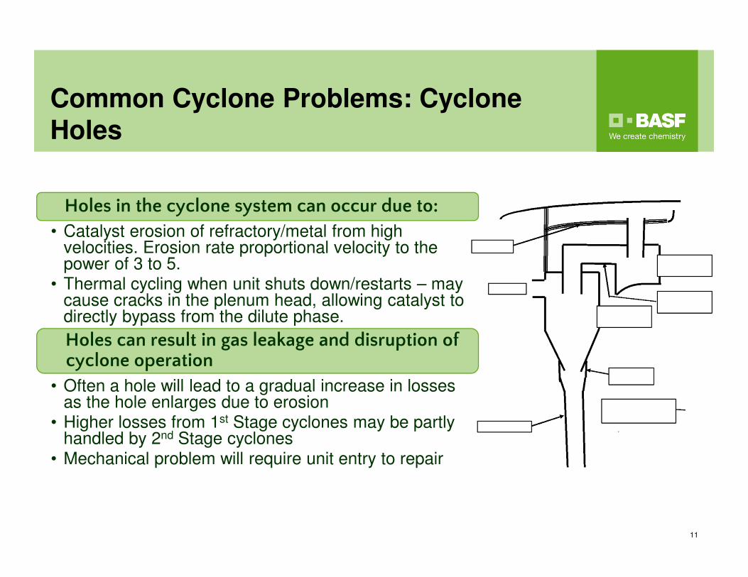
Holes in the cyclone system can occur due to:
• Catalyst erosion of refractory/metal from high velocities. Erosion rate proportional velocity to the power of 3 to 5.
• Thermal cycling when unit shuts down/restarts – may cause cracks in the plenum head, allowing catalyst to directly bypass from the dilute phase.
Holes can result in gas leakage and disruption of cyclone operation
• Often a hole will lead to a gradual increase in losses as the hole enlarges due to erosion
• Higher losses from 1st Stage cyclones may be partly handled by 2nd Stage cyclones
• Mechanical problem will require unit entry to repair
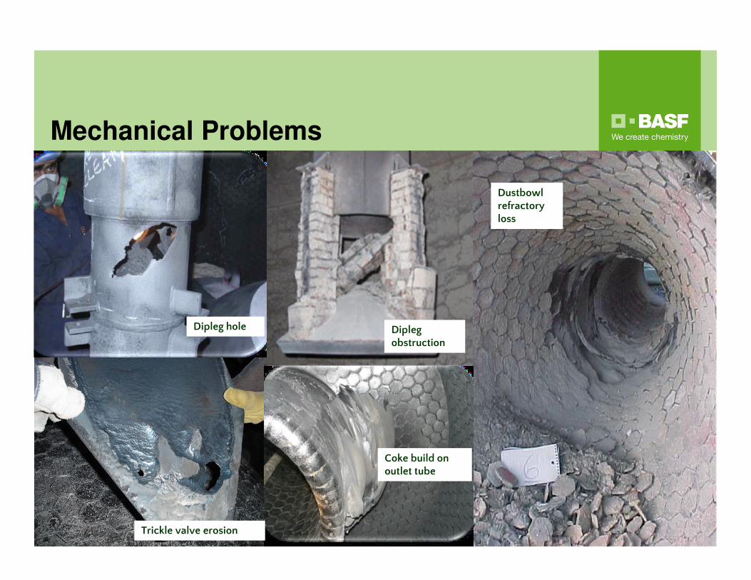
Mechanical Problems
12
Dipleg hole
Coke build on outlet tube
Trickle valve erosion
Dipleg obstruction
Dustbowl refractory loss
Reactor Cyclone Coking
13
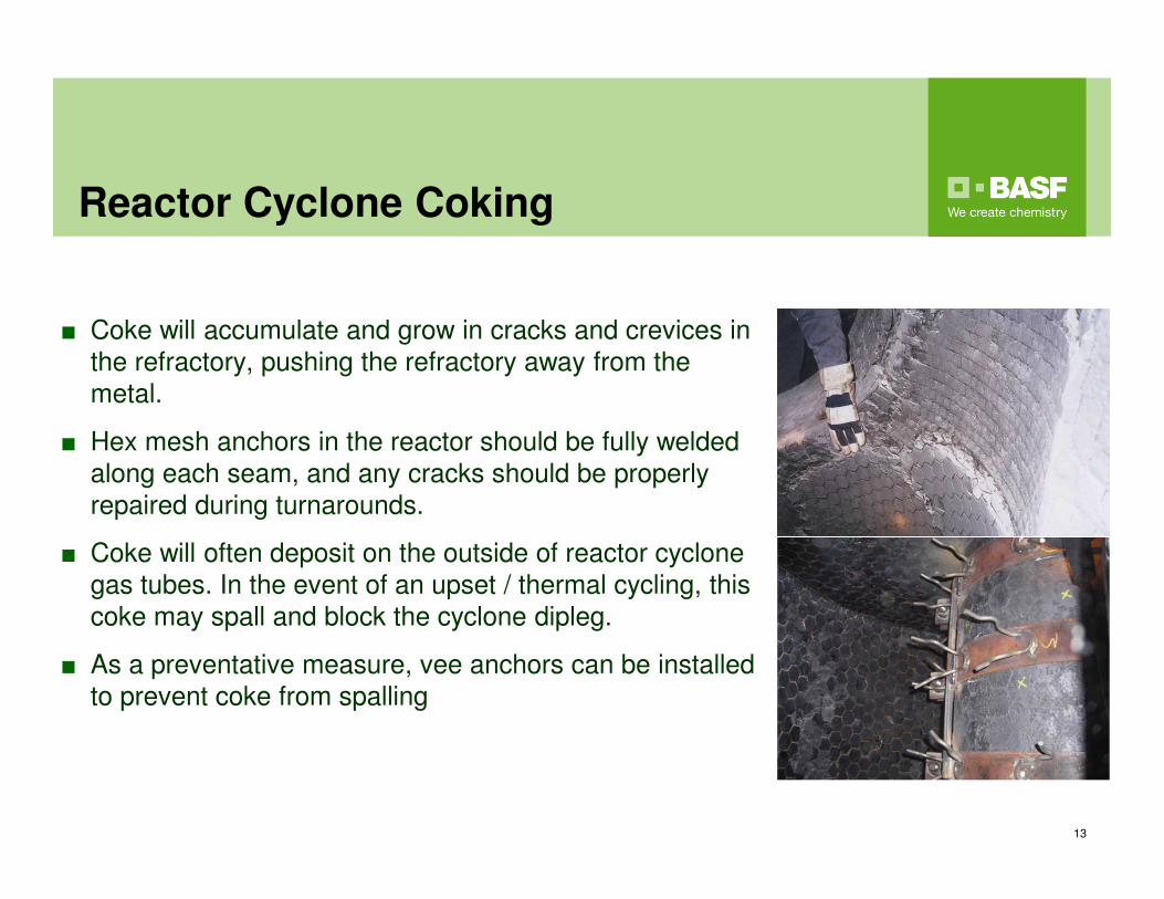
■ Coke will accumulate and grow in cracks and crevices in
the refractory, pushing the refractory away from the
metal.
■ Hex mesh anchors in the reactor should be fully welded
along each seam, and any cracks should be properly
repaired during turnarounds.
■ Coke will often deposit on the outside of reactor cyclone
gas tubes. In the event of an upset / thermal cycling, this
coke may spall and block the cyclone dipleg.
■ As a preventative measure, vee anchors can be installed
to prevent coke from spalling
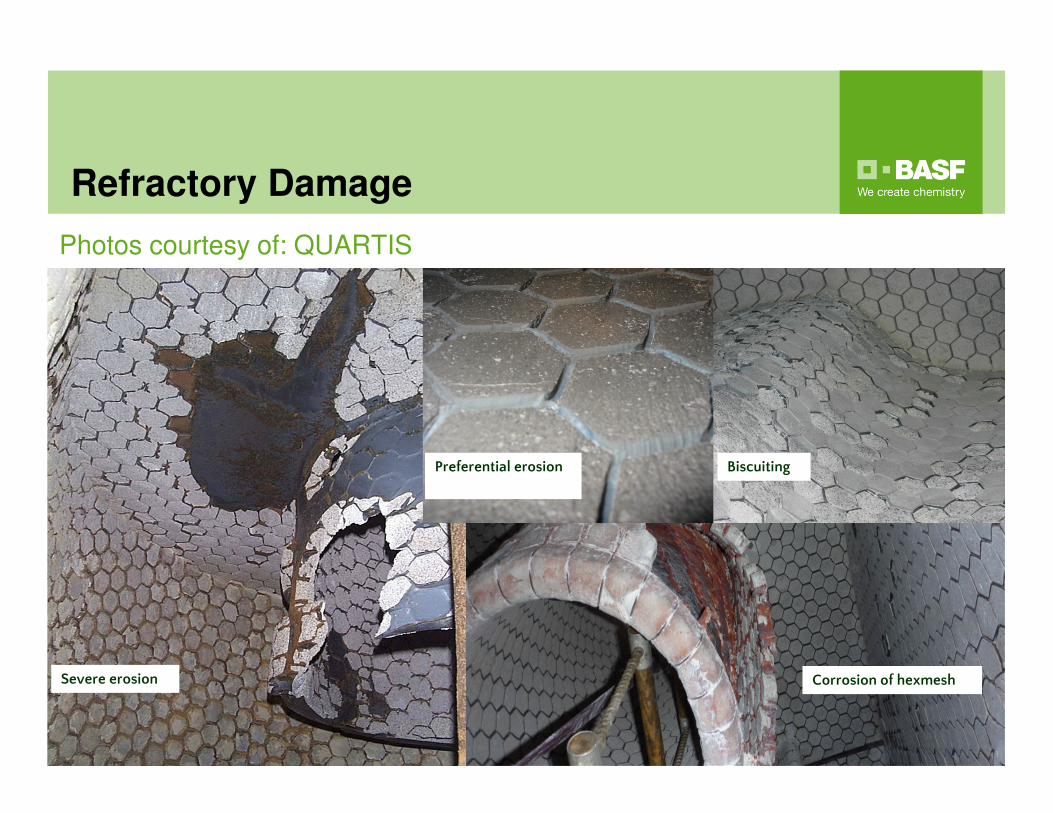
Refractory Damage
Photos courtesy of: QUARTIS
14
Severe erosion
Preferential erosion
Corrosion of hexmesh
Biscuiting
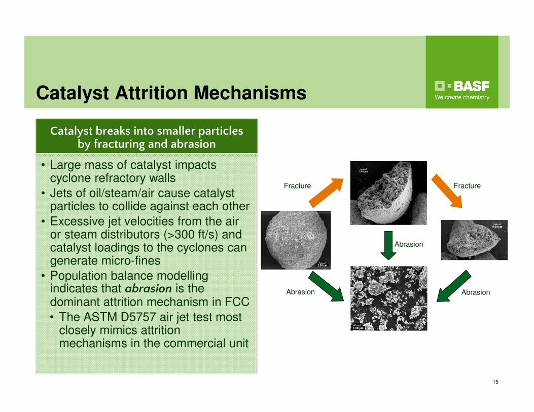
Catalyst Attrition Mechanisms
15
Fracture
Abrasion Abrasion
Fracture
Abrasion
Catalyst breaks into smaller particles by fracturing and abrasion
• Large mass of catalyst impacts cyclone refractory walls
• Jets of oil/steam/air cause catalyst particles to collide against each other
• Excessive jet velocities from the air or steam distributors (>300 ft/s) and catalyst loadings to the cyclones can generate micro-fines
• Population balance modelling indicates that abrasion is the dominant attrition mechanism in FCC
• The ASTM D5757 air jet test most closely mimics attrition mechanisms in the commercial unit
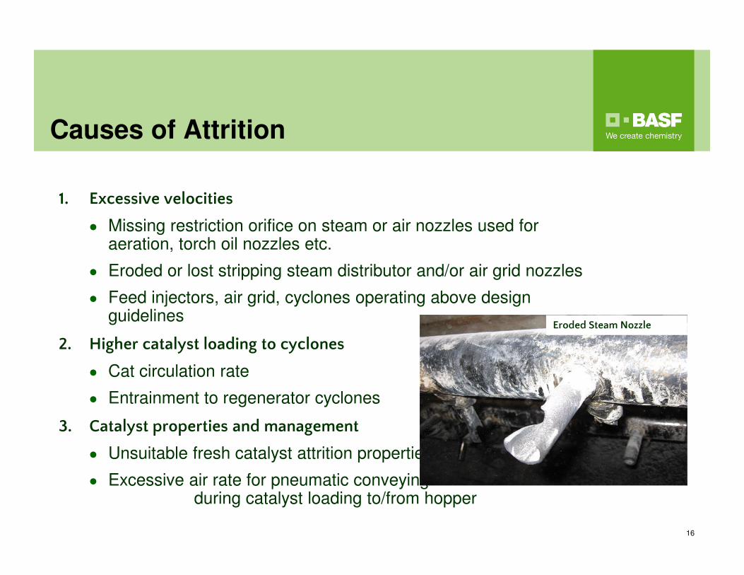
Causes of Attrition
16
1. Excessive velocities
● Missing restriction orifice on steam or air nozzles used for aeration, torch oil nozzles etc.
● Eroded or lost stripping steam distributor and/or air grid nozzles
● Feed injectors, air grid, cyclones operating above design guidelines
2. Higher catalyst loading to cyclones
● Cat circulation rate
● Entrainment to regenerator cyclones
3. Catalyst properties and management
● Unsuitable fresh catalyst attrition properties
● Excessive air rate for pneumatic conveyingduring catalyst loading to/from hopper
Eroded Steam Nozzle
Catalyst Attrition Properties
17
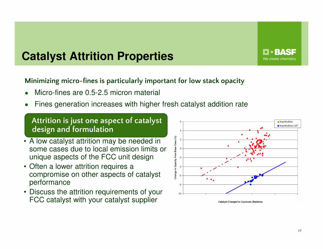
Minimizing micro-fines is particularly important for low stack opacity
● Micro-fines are 0.5-2.5 micron material
● Fines generation increases with higher fresh catalyst addition rate
Attrition is just one aspect of catalyst design and formulation
• A low catalyst attrition may be needed in some cases due to local emission limits or unique aspects of the FCC unit design
• Often a lower attrition requires a compromise on other aspects of catalyst performance
• Discuss the attrition requirements of your FCC catalyst with your catalyst supplier
Catalyst Loss Monitoring
18
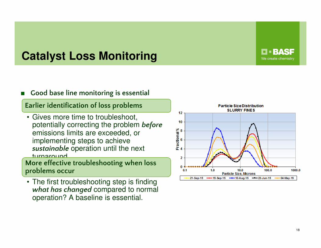
Earlier identification of loss problems
• Gives more time to troubleshoot, potentially correcting the problem beforeemissions limits are exceeded, or implementing steps to achieve sustainable operation until the next turnaroundMore effective troubleshooting when loss problems occur
• The first troubleshooting step is finding what has changed compared to normal operation? A baseline is essential.
■ Good base line monitoring is essential
Catalyst Balance
19
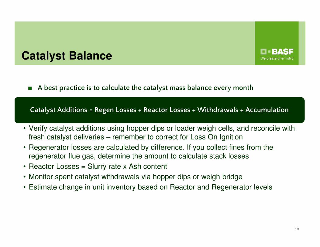
Catalyst Additions = Regen Losses + Reactor Losses + Withdrawals + Accumulation
• Verify catalyst additions using hopper dips or loader weigh cells, and reconcile with
fresh catalyst deliveries – remember to correct for Loss On Ignition
• Regenerator losses are calculated by difference. If you collect fines from the
regenerator flue gas, determine the amount to calculate stack losses
• Reactor Losses = Slurry rate x Ash content
• Monitor spent catalyst withdrawals via hopper dips or weigh bridge
• Estimate change in unit inventory based on Reactor and Regenerator levels
■ A best practice is to calculate the catalyst mass balance every month
Catalyst Loss Monitoring
20
■ Additional monitoring of the unit should include:
● Regular review of fresh catalyst properties – PSD, ABD, LOI, Attrition
Index
● Weekly testing of equilibrium catalyst physical properties – PSD, ABD
● Particle size analysis of slurry fines, third stage fines, etc. at least monthly
● Slurry ash content 1-2 times per week,
and daily BS&W testing■ A regular review of data and monthly catalyst balance will give the best chance to identify a loss problem
● It may take several weeks for a loss
problem to be confirmed
Catalyst Loss Troubleshooting:
Identifying the Problem
21
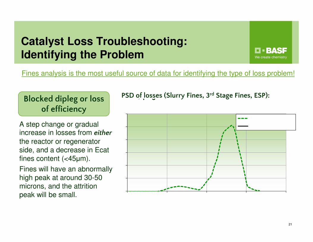
PSD of losses (Slurry Fines, 3rd Stage Fines, ESP):
A step change or gradual increase in losses from eitherthe reactor or regenerator
side, and a decrease in Ecat
fines content (<45μm).
Fines will have an abnormally
high peak at around 30-50
microns, and the attrition
peak will be small.
Blocked dipleg or loss of efficiency
Fines analysis is the most useful source of data for identifying the type of loss problem!
Catalyst Loss Troubleshooting:
Identifying the Problem
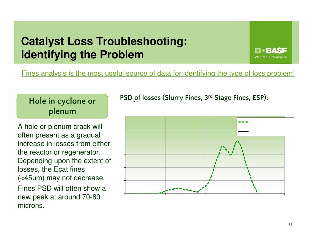
Fines analysis is the most useful source of data for identifying the type of loss problem!
PSD of losses (Slurry Fines, 3rd Stage Fines, ESP):
A hole or plenum crack will
often present as a gradual
increase in losses from either
the reactor or regenerator.
Depending upon the extent of
losses, the Ecat fines
(<45μm) may not decrease.
Fines PSD will often show a
new peak at around 70-80
microns.
Hole in cyclone or plenum
22
Catalyst Loss Troubleshooting:
Identifying the Problem
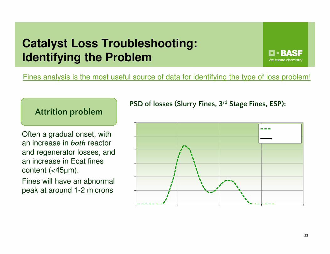
Fines analysis is the most useful source of data for identifying the type of loss problem!
PSD of losses (Slurry Fines, 3rd Stage Fines, ESP):
Often a gradual onset, with an increase in both reactor
and regenerator losses, and
an increase in Ecat fines
content (<45μm).
Fines will have an abnormal
peak at around 1-2 microns
Attrition problem
23
Investigation Steps to Consider
24
■ Review the nature of the losses:
● Gradual increase with increased <2.5μm peak in fines PSD → Attrition
● Gradual increase with increased peak in fines PSD ~ 70μm → Hole
enlarging
● Step change → Mechanical failure or operating problem
● Intermittent → Operating close to cyclone dipleg flooding limit■ Check potential attrition sources: Equipment velocities,
steam distributor P, catalyst properties/additions, confirm all
flow RO’s in place, blast steam closed, etc.
■ Review operating conditions: Sudden loss in vessel
pressure, regenerator bed defluidization due to low air rate,
higher feed rate leading to reactor cyclone flooding, etc.
■ Review inspection history: Has a similar problem occurred
in the past?
■ Conduct tests: Gamma scans for vessel and cyclone dipleg
levels, radioactive tracers for gas/catalyst flow distribution,
etc.
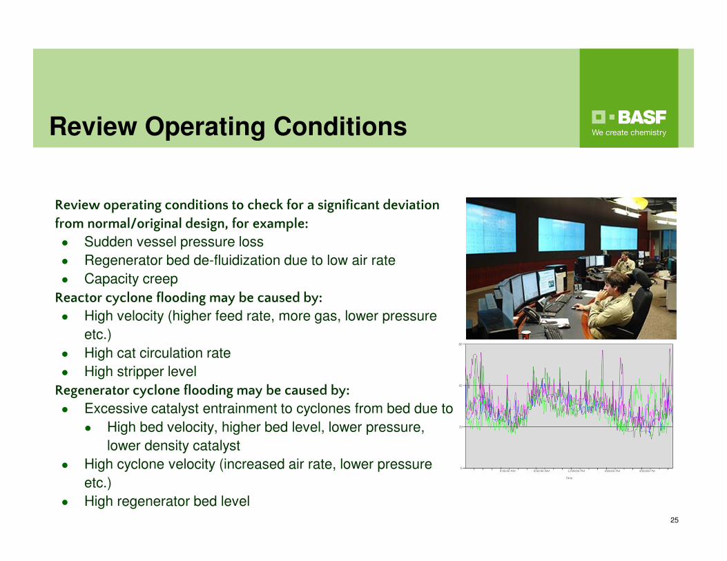
Review Operating Conditions
25
Review operating conditions to check for a significant deviation
from normal/original design, for example:
● Sudden vessel pressure loss
● Regenerator bed de-fluidization due to low air rate
● Capacity creep
Reactor cyclone flooding may be caused by:
● High velocity (higher feed rate, more gas, lower pressure
etc.)
● High cat circulation rate
● High stripper level
Regenerator cyclone flooding may be caused by:
● Excessive catalyst entrainment to cyclones from bed due to:
● High bed velocity, higher bed level, lower pressure,
lower density catalyst
● High cyclone velocity (increased air rate, lower pressure
etc.)
● High regenerator bed level
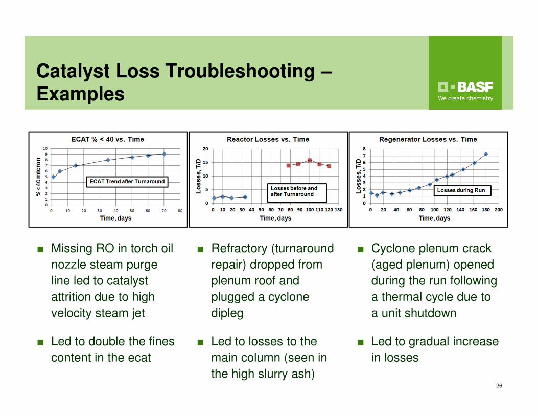
Catalyst Loss Troubleshooting –
Examples
■ Refractory (turnaround
repair) dropped from
plenum roof and
plugged a cyclone
dipleg
■ Led to losses to the
main column (seen in
the high slurry ash)
■ Cyclone plenum crack
(aged plenum) opened
during the run following
a thermal cycle due to
a unit shutdown
■ Led to gradual increase
in losses
■ Missing RO in torch oil
nozzle steam purge
line led to catalyst
attrition due to high
velocity steam jet
■ Led to double the fines
content in the ecat
26
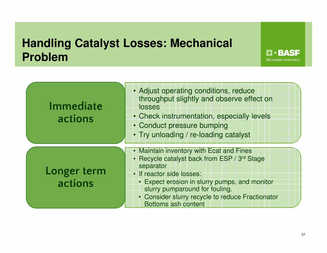
Handling Catalyst Losses: Mechanical
Problem
27
• Adjust operating conditions, reduce throughput slightly and observe effect on losses
• Check instrumentation, especially levels
• Conduct pressure bumping
• Try unloading / re-loading catalyst
Immediate actions
• Maintain inventory with Ecat and Fines
• Recycle catalyst back from ESP / 3rd Stage separator
• If reactor side losses:
• Expect erosion in slurry pumps, and monitor slurry pumparound for fouling.
• Consider slurry recycle to reduce Fractionator Bottoms ash content
Longer term actions
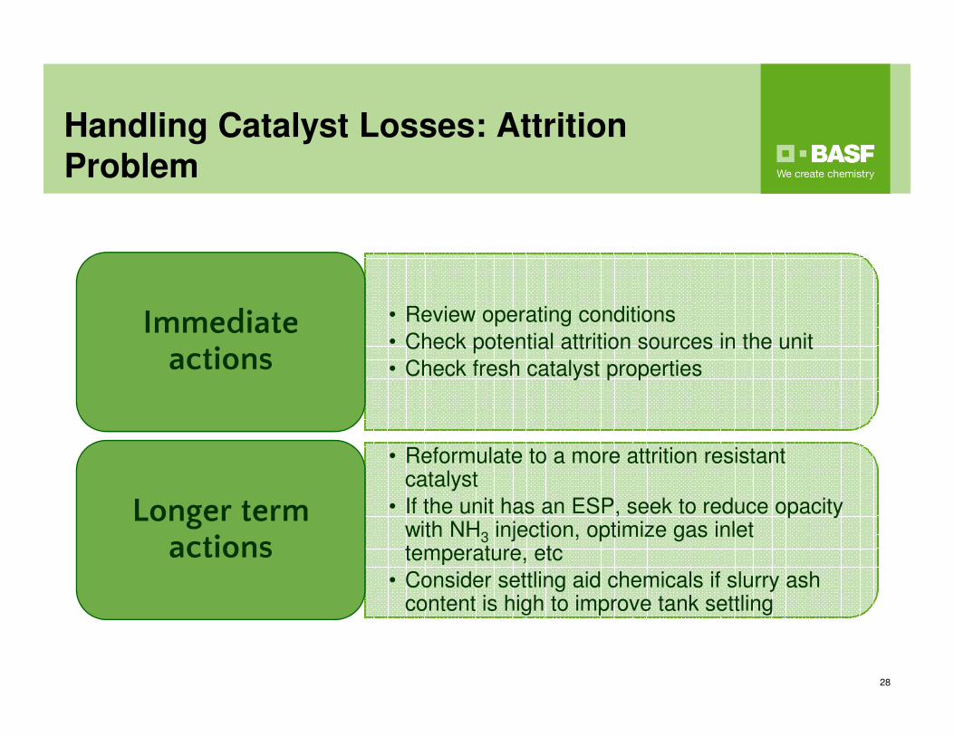
Handling Catalyst Losses: Attrition
Problem
28
• Review operating conditions
• Check potential attrition sources in the unit
• Check fresh catalyst properties
Immediate actions
• Reformulate to a more attrition resistant catalyst
• If the unit has an ESP, seek to reduce opacity with NH3 injection, optimize gas inlet temperature, etc
• Consider settling aid chemicals if slurry ash content is high to improve tank settling
Longer term actions
Appendix
30
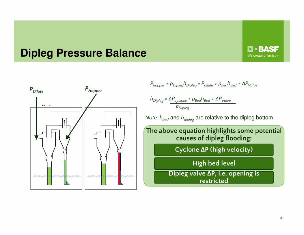
Dipleg Pressure Balance
31
Phopper + ρDipleghDipleg = Pdilute + ρBedhBed + ΔPValve
hDipleg = ΔPcyclone + ρBedhBed + ΔPValve
ρDipleg
PDilutePHopper
Note: hbed and hdipleg are relative to the dipleg bottom
The above equation highlights some potential causes of dipleg flooding:
Cyclone ΔP (high velocity)
High bed level
Dipleg valve ΔP, i.e. opening is restricted


![[Music Sheet] Alan Kuo - Ling (Mars)](https://static.documents.pub/doc/80x56/5571f8b749795991698df0c8/music-sheet-alan-kuo-ling-mars.jpg)


![[Kuo-Yann Lai] Liquid Detergents(BookZZ.org)](https://static.documents.pub/doc/80x56/55cf969b550346d0338ca125/kuo-yann-lai-liquid-detergentsbookzzorg.jpg)


